Embed Size (px)
Citation preview

AN INTRODUCTION TOMACHINING PRACTICES
CORNELL UNIVERSITYEMERSON PRODUCT REALIZATION LABORATORY
116 FRANK H. T. RHODES HALLITHACA, NEW YORK 14853-3801

Page 2
The Emerson Laboratory
What is the Emerson Laboratory?
Simply stated, it is an area where students, faculty, staff, and all other members of the Cornell communitymay use the available machine tools to facilitate completion of their projects and/or coursework.Mechanical Engineering students use the shop to support the various projects in their curriculum includinglaboratory sessions. Many users fabricate items related to design projects, such as the HEV and FormulaSAE projects within the engineering college, as well as other team projects throughout the University.Staff members fabricate equipment needed by faculty for research projects. Emerson may even be usedfor personal fabrication projects.
Where is the Emerson Laboratory?
The machine shop (Emerson Manufacturing Teaching Laboratory) is located on the first floor of FrankH.T. Rhodes Hall. When entering the building from the front entrance, turn left after the reception area.The door straight ahead (Room 116) is the shop. Feel free to walk in and look around.
Capabilities of the Emerson Laboratory
What can be done in the Emerson Laboratory?
Anyone who has had the proper training on the available equipment may use the shop for fabrication ofparts made from the various metal alloys. We are not able to fabricate from wood, phenolic, epoxy glass,and other materials that create large amounts of residual dust. Metal alloys are the only permissiblematerials allowed. There are some exceptions to this rule that should be discussed with shop personnel asthe situation arises.
The shop keeps a small inventory of tooling, but Emerson does not have all the tooling that might benecessary for all projects. Technical Service Facilities (TSF), located in the basement of Upson Hall, hasa stockroom of tooling available for purchase or use. Tooling may “borrowed”, if it is available, by usingthe log out system they have in place. TSF also stocks some raw materials (i.e. screws, nuts, bolts, etc.)that may need to be purchased for projects.
What machines are available in the Emerson Laboratory?
The shop currently has a variety of machine tools. In most cases, more than one of each is available.Please be aware of the hours of operation of the lab and the limitations of each machine as explained in thismanual.
Here is a list of available equipment:
Horizontal Bandsaws (2) Disc Sander (1)Vertical Bandsaw (1) CNC Milling Machines (2)Drill Presses (3) CNC Lathe (1)Vertical Milling Machines (2) Instrons (2) [used for material testing, load frames]Horizontal Milling Machine (1) Coordinate Measuring Equipment (Metrology Cell)Lathes (9) Welders:Belt Sander (1) MIG, TIG, Stick and Oxy-acetlene
There are signs near each machine to explain their operation and safety rules. If theyare unclear, please ask for a clarification!

Page 3
Design Concepts
This section is provided to help plan the activities in the shop during the design stage of a project. Ifmanufacturing issues are considered early in the design, time and frustration during the actual fabricationcan be saved. Plan the design thoroughly with specific sketches and detailed drawings for constructionand machining. The following list of questions is to get you thinking about some important conceptsduring the design process. If you cannot answer all of these questions, do not get frustrated since some ofthem are open ended. The answers will fall into place as experience is gained. Read through this list andfamiliarize yourself with these concepts. Remember, a design that cannot be built is a failure!
General design tips
Can the design be made? Will slight modifications make it easier?Is there already something which does what I need?Am I using standard sizes?Will the part have uses other than the intended?Will the part be subjected to harmful environmental conditions?What tradeoffs can I live with in the design?
Can it be fabricated?
Can it be made in the shop?Where will I get the materials?Which tools will I need to use?How accurate does it have to be? (i.e. what are the tolerances needed?)What are the machining steps required? Is this the minimum number of steps?How long will it take?
Ease of machining
In what order will I perform the machining?What is the easiest material I can work with?What needs to be accurate, and more importantly, what does not?Is this a one of a kind, or will it be duplicated again later?

Page 4
The purpose of this manual is to introduce the various hand operated machinery, tools, andassociated tooling available for student use in Emerson Laboratory.
Instruction will be basic in nature, and should not be considered a certification course inmachine operation.
Specialized instruction may be required at the time of actual machine use, and will beprovided by laboratory personnel as their time permits.
CAUTIONIMPROPER USE OF ANY MACHINE TOOLS MAY RESULT IN SEVERE
INJURY OR DEATH. MANDATORY ADHERENCE TO ALL SAFETY RULESIS REQUIRED. EXPULSION FROM THE LABORATORY WILL RESULT
FROM NON-COMPLIANCE WITH THESE RULES.

Page 5
Safety Rules
These rules have been broken down into three general categories:General Shop SafetyPersonal SafetySafety in the Work Environment
General Shop Safety1. Radios, CD Players, headphones, etc. are not permitted in the lab.
2. No food or drink of any kind is permitted in the shop areas, including the CIM Computer facility.
3. All equipment operators and their work will be shown the proper respect by those using this facility.
4. All accidents and injuries will be reported to the Shop Supervisor IMMEDIATELY.
5. Any transportation of injured individuals is to be done only by qualified personnel. Call 5-1111(Cornell Police) for assistance.
Personal Safety1. Proper eye protection will be worn in the machine shop area at all times. Shop users wishing to use
their personal glasses must document that the lenses and frames are rated for this purpose.
2. Proper footwear will be worn at all times. No bare feet, shoes with open toes, slippers, high heels orsandals are permitted.
3. Secure all loose clothing, jewelry, neckties, hair, etc. so that it cannot become entangled in theequipment.
4. No gloves are to be worn while operating any of the equipment, with the exception of welding gloves.
5. Plastic gloves must be worn whenever first aid involving open wounds is being administered toanother. Also, all medical waste will be disposed of in the proper manner.
Workplace Safety1. Work areas, benches, and aisles will be kept clear and free of obstructions. Coats and backpacks
should be stored on the coat rack at the front of the lab.
2. No equipment will be used for any purpose other than that for which is was specifically designed.
3. No equipment is to be left running while either physically or mentally unattended.
4. No equipment will be operated without its guards, shields, and safety locks in place and functioning.
5. Any oil or grease spilled on the floor will be cleaned up IMMEDIATELY and disposed of in the propermanner.
6. No keys will be left in the chucks of the lathes or drill presses.
7. Only one operator per machine is allowed. Special jobs involving more than one operator require thepermission of the Shop Supervisor. Exception to this rule is only during instructional purpose and/ortraining sessions.
These are basic safety rules which apply to the lab in general. Each machine tool and piece of testequipment has its own additional safety rules and considerations. It is the operator's responsibility to befamiliar with these before using any equipment. Training on a particular piece of equipment will be doneat the convenience of the laboratory staff.

Page 6
Operating Procedures
1. No non-metallic materials will be machined without prior approval.
2. Any damaged, broken, or unsafe equipment will be reported to lab personnel IMMEDIATELY.
3. Users are responsible for knowing the correct operating procedures and any associated safety rules forthe equipment they are using. Shop personnel are there to answer questions or show you how to getanswers.
4. All tools and materials will be returned to their correct storage area IMMEDIATELY upon completionof work.
5. All chips and scraps are to be cleaned from machines, floors, and bench tops IMMEDIATELY uponcompletion of work.
6. Work is not to be left set up in machines for more than one (1) hour without prior approval. Work leftpast this time may be removed to make equipment available to others.
7. Shop hours are 8:00 AM to 5:00 PM., with clean up starting promptly at 4:30 PM. Changes to thesehours will be posted on the door in advance. It is the users’ responsibility to note them and planaccordingly.
8. There is a clipboard and pen next to each machine - sign in each time you use the machine with yourname and phone number.
Clean-Up Procedures
This is a general guideline of the clean-up procedures for the Emerson shop
1. Make sure to sweep up the chips on the floor and on the machine. This includes all parts of themachine (i.e. table, tool holder, slots, collets, etc.).
2. Clean up any excess oil that is on the machine or the floor. This includes any oil which may havegotten onto the vise, tabletop, etc.
3. Put away all the hand tools that were used in their appropriate spots.

Page 7
Terminology
Arbor: A device used to hold cutting tools on a milling machine. It is used for cutters rather thanendmills.
Backlash: The “slop” or discrepancy between actual distance and measured distance when using thetable’s travel handles on a lathe or a milling machine. Backlash occurs when the direction of rotationof the handle is changed: the handle has to be rotated a little before it “catches” and moves the table.
Center Drill: A short stubby drill used to start holes. This drill is double ended, where either end can beused. Since it is short and stubby, it does not deflect upon contact with the workpiece and can beused to create an accurately positioned pilot hole.
Center Punch: A metal device that is gently hit with a hammer to create a dimple that helps to guide thedrill bit to the proper location. Without this dimple, the drill bit can “walk” away from the desiredlocation.
Chips: The pieces of material that are removed from a workpiece through machining; shavings.
Chuck: A device used to hold items. A drill chuck is used to hold a drill bit to the spindles on a drillpress or to the tailstock on a lathe. A different kind of chuck is used to hold a workpiece to theheadstock on a lathe.
Chuck Key: A wrench used to tighten the jaws of a chuck around whatever the chuck is holding, or toloosen the jaws.
Collet: A device used to hold an endmill inside the spindle on a milling machine.
Dead Center: A device that is placed into the tailstock of a lathe in order to hold a long workpiece. ItDOES NOT rotate with the workpiece whereas the live center does rotate with the workpiece.
Drill Bit Gauge: A device used to measure the size of a drill bit if the size is not visible on the shank. Adrill bit gauge has many different sized holes, all labeled a different size.
Drilling: Making a hole in a workpiece by pushing a rotating cutting tool into a stationary workpiece.Drilling is performed on a drill press or a milling machine.
Edge Finder: Two concentric cylinders that are spring loaded together. It can be placed in a collet of amilling machine.
Endmill: A cutting tool used on a milling machine to cut the side of a workpiece.
External Operations: Procedures followed to machine the outside surface of a workpiece.
Facing: An external operation performed on a lathe which wears down the end surface to bring aworkpiece to a desired length and/or to make the end surface plane and square. The work is rotatedagainst a fixed cutting tool, i.e. such as making a cylinder shorter and giving it a finished endsurface.
Feed Lever: A handle used to lower the spindle to the workpiece on a drill press or milling machine.
Headstock: The part on a lathe that holds the chuck which holds the workpiece.
Internal Operations: Procedures followed to machine the inside surface of a workpiece.
Live Center: A device placed in the tailstock of a lathe to hold a workpiece that may be long. Thiscenter rotates with the workpiece whereas a dead center does not rotate with the workpiece.

Page 8
Milling: Any operation performed on a milling machine using a rotating cutter or endmill to removematerial from a workpiece.
Pitch: The number of teeth per inch on a blade.
Shank: The smooth part of a drill bit that is held by the drill chuck. The drill bit size is stamped on theshank.
Spindle: The part of a drill press or milling machine which is spun by the motor, it holds a chuck, collet,or arbor.
Tailstock: The part on a lathe that holds a drill chuck or holds the outer end of a long workpiece. It isadjustable to accommodate different lengths.
Tap: A device that looks similar to a screw only it has straight flutes cut into the sides to allow the chipsto be expelled. This device threads holes that have been drilled.
Turning: An external operation performed on a lathe which shapes the side surface of a rotatingworkpiece with a cutting tool, i.e. such as making a cylinder with a smaller diameter.

Page 9
Section One: HORIZONTAL BANDSAWVERTICAL BANDSAW
These machine tools are not only versatile in their configurations, but in their functions as well. Thoughthey are all used for cutting raw stock of various materials into smaller or more machine adaptable blanks,each type has a specific purpose and use. The name “bandsaw” comes from the serrated sawblade whichforms a continuous loop around two pulleys, one pulley is driven by a motor, the other is idle.
HORIZONTAL BANDSAW
The horizontal bandsaw has an automatic feeding head, so that when it is properly configured, the cuttingoperation is carried out automatically. The following guides will help in the operation of this type of saw.
1. Assure the blade is the proper one for the material being cut. Blades vary in pitch and style (offset,wave, etc.). Generally a multi-purpose blade is used which is applicable to most tasks. Makesure that at least 3 teeth come in contact with the stock. If less than three teeth are incontact, the teeth could shear off the blade, destroying the blade and damaging the workpiece.Thin stock, such as sheet metal is too thin for this machine, use shears to cut this material.
2. If it is necessary to change the angle of cut, loosen the bolts and pull out the pins of the side guide.Make sure the bolt is secure in the new configuration. Remember to return the side guideto the 90 degree configuration when finished.
3. Make sure that the sliding weight is on the lower pressure setting. Do not move this weightnor lean on the end of the saw to increase the pressure. This will pop the blade out ofthe guides or shear the teeth off the blade. to make sure the guides are in the proper position andthat the guide will not hit the saw casing.
4. Place the workpiece between vise jaws and adjust them for proper clamping. Wiggle the part tomake sure it is secure to prevent movement during the cutting operation.
5. Turn the saw on and lubricate the blade with the wax compound, “chapstick”. DO NOT PLACEYOUR HANDS UNDER THE CASING AROUND THE PULLEYS. Carefully lower the headuntil it comes in contacts with the workpiece. Do not let the saw drop onto the workpieceor it will bounce, causing the blade to pop off. Release the head and allow the saw tofeed through the material. THE SAW AUTOMATICALLY SHUTS OFF WHEN COMPLETED.
VERTICAL BANDSAW
The vertical bandsaw is the most widely used saw with the only limitation being the size of the stock beingcut. The following is a general guide for its operation.
1. Assure the blade is the proper one for the material being cut. Blades vary in pitch (number of teethper inch) and style (offset, wave, etc.). Check the posterboard to determine the proper blade forthe material being used.
2. Adjust the blade guides for proper spacing by raising or lowering to allow for material thickness.Remember: The less blade exposed the safer the cutting operation.
3. Turn the saw on and adjust the speed for the desired material to be cut. ADJUST SPEED ONLYWHEN SAW IS RUNNING. There is a dial mounted on the upper saw door charting speeds formost types of materials. If unsure of desired speed, ASK LAB PERSONNEL.
4. Carefully apply wax type lubricant to the blade with a firm and steady pressure. STOP EVERY SOOFTEN TO RE-APPLY THE LUBRICANT. Use a piece of wood or stock guide, not yourhands, to guide the stock through the blade. DO NOT PUSH STOCK WITH HANDS IF THEYARE IN LINE WITH THE BLADE.
Page 10
Section Two: DRILL PRESSES
A drill press is used for drilling a vertical hole in a stationary workpiece by removing solid material. Thisincludes such tasks as:
a) hole drillingb) tapping (process of threading for internal screw threads)c) countersinking (for use with flathead type screws)d) counterboring (for flush mounting of screw heads other than flathead)e) reaming (used to obtain critical tolerancing of diameters)
For drilling very precise holes, use the lathe or the milling machine.Figure fromme.mit.edu/lectures/machine/drill/drill.gif
Note:
All of our drill presseshave variable speedmotors. Change speedsonly after machine isrunning. However,speeds should bereduced for average shoptooling.
The following is a brief step-by-step operation guideline of this tool. These directions are in no waycomplete and are meant to be a supplement to the required machine course.

Page 11
1. In order to drill in a precise location it is necessary to use a center punch or center drill:Center Punch: Place the tip of the center punch in the center of the desired hole and tap it lightly
with a hammer to make a small indentation. Be sure that the center drill is not the spring loadedkind, which does not need to be tapped with a hammer.
Center Drill: A short, stubby double ended drill bit. Use a center drill slightly smaller than the drillbit used to make the hole. Place it in the chuck, tighten it and then turn the drill press on andcreate the pilot hole. It is not necessary for the center drill to go all the way in.
2. Determine the drill size. In the U.S., there are fractional inch sizes as well as ‘letter’ sizes and tiny‘number’ sizes. The hole may be accurately sized, to fit a shaft or bushing, or be threaded for abolt. It can also be carelessly sized if a precise fit is not necessary.Hint: Use a drill size slightly smaller than necessary. It is easier to remove more material than it
is to replace material.
3. Insert the drill bit into the chuck and tighten securely. Run the drill to make sure the bit rotatesstraight, if it does not, ask for help from the lab personnel.
4. Secure the workpiece down securely in a vise to prevent the work from being torn from theoperators. Be sure that the vise is secured to the table to prevent the work from being picked up asthe quill is raised. Make sure that you do not drill into the vise or the table. Protectthe table surface by using a piece of scrap material, such as wood, under the workpiece
5. Check to be sure that all operations are performed with a minimum extension of the quill. Adjustthe table or headposition to minimize the quill travel. Lock the table securely in all directions toprevent it from moving.
6. Select the proper rate of rotation for the tool by using the chart at the end of this section. Turn themachine on and turn the handle to adjust the speed. DO NOT USE THE CHART ON THEFRONT OF THE MACHINE. It is based on production usage with ideal conditions, such assharp bits, perfect workpieces, etc. ADJUST THE SPEED OF THE MACHINE ONLY WHENIT IS RUNNING. If there is any squeaking or chattering from the drill orworkpiece, slow the speed down.
Hint: The larger the drill bit, the slower the speed.The harder the material, the slower the speed. For steel, the individual flutes of the drill should be
seen. Aluminum can be done at a slightly higher rate since it is softer.
7. Always use cooling oil or other recommended coolants during drilling operations. This isnecessary to extend the tool life and prevent damage to the workpiece. The oil is color codedinto container: aluminum uses A-9 (blue top container), and the remaining metalsuse Dark Oil (red top container).
8. Turn on the machine and start the drilling cycle. Do not let the drill bit sit on the top of theworkpiece, apply slight pressure. Use "pecking" motions to prevent jamming of chips which cancause tool breakage. Feed the quill more slowly just before completing the hole in order to preventsudden breakthrough; this will prevent the drill from grabbing and/or pulling the workpiece loosefrom its fixture.
Clear away chips with a brush from the oil container, they are sharp and can cut your hand.Guide the spindle back up by hand, otherwise it could hit someone in the head.
TAPS/THREADSUse the tap guide on the wall near the lathes for determining the proper equipment. If still unsure,
ask for assistance.Fasteners are designated by the diameter, number of threads per inch, and shape. For instance, a
1/4-20NC screw is 1/4 inch in diameter, has 20 threads per inch and follows the NationalStandard. Fasteners smaller than a 1/4 inch in diameter are designated by a number from 0(smallest) to 12 (largest).

Page 12
When using a tap to thread a hole, be careful. The taps are fragile and easy to break so it isnecessary to turn counterclockwise every so often to break the chips.
SAFETY TIPS:-When removing the bits, do not let them drop. This will chip and destroy the bits and their ends.-Never try to use the drill press as a mill, i.e. do not cut sideways.-Never try to grab at the chips or workpiece if they get picked up off the table and are spinning.-If trying to drill non-flat material, the drill may skid off ‘downhill’. DO NOT bend the drill bit, it will
eventually snap.

Page 13
Section Three: VERTICAL MILLING MACHINES
The vertical milling machine is the most common of the milling machine family. Some shop environmentsrequire both horizontal and vertical type machinery. Other than the position of the head (horizontal orvertical) the machine operation is basically the same.
These machines are capable of the most simple tasks, such as drilling, to the more complicated tasks suchas milling contours or shaping surfaces. Most of the operations performed will be limited to the simplesttasks. These tasks can be accomplished by using the machine in its basic set-up: a vise clamped to thetable for holding the workpieces and the use of the standard collets (tool holders) supplied with eachmachine. It will be a matter of selecting the proper tool and speed for the job. When non-standardfixturing and specialized tooling are necessary, training will be provided by the lab personnel. Onlythrough years of exposure to all of the possibilities of machine operation, does one become proficient inthe varieties of the set up and operation of this type of machine. Extensive knowledge of machineoperation, fixturing, and the basics of machining principles play important roles in the proficient use ofthese types of machines.
The vertical axis mill looks very similar to a drill press. The spindle, where the rotating cutting tool isheld, is located in about the same position relative to the table as it is in a drill press. The difference is thaton a drill press, the tool is moved against a stationary workpiece. On a milling machine, the cutting tool iscapable of cutting on its SIDES as well as its end and the work is capable of being translated relative to thecutting tool, to form slots or edges. The table of the vertical mill can be moved by hand or by power.Overall, the milling machine is more precise and sturdier than a drill press. The most common operationsperformed on a milling machine are:
cutting a workpiece to a precise sizecutting slots or long holesdrilling a pattern of holes in precise locations"squaring up": making a surface square and plane.
Cutting tools are held by a ‘collet’ system. These are special tapered sleeves which squeeze tight whenthey are forced into a conical hole. On the smaller mills, the collet is pulled up by a bolt on top of thespindle. The collet is held in by the shape of the conical hole and not by how tight the bolt is tightened ontop. Drill bits cannot be placed into the collets!
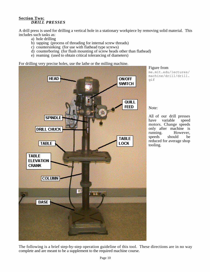
Once these simple principles have been mastered, you will be ready to look into power feeds, flycutting,T-slots, etc. The diagram on the following page is a close-up of the head assembly of a Bridgeport millingmachine. It is intended to familiarize you with the available controls. Not all machines have this controlconfiguration, but all are capable of similar operations. Due to the complexity of its operation,demonstration of this machine is limited to the very basic operating fundamentals.
(figure from http://www.machinist.org/harvard_cotreau/mshop1.html)
Page 14
The following is a brief guideline for getting started on the mill. These directions are in no way completeand are meant to be a supplement to the required machine course.
1. Select a cutter: end mills or angle milling cutters
2. Select a cutter holding device: collet for an end mill, arbor for a plain or angle cutterNever attempt to use tool holders for anything other than their intended purpose, i.e. DO NOT
USE COLLETS OF LARGER DIAMETER FOR SMALLER DIAMETER SHANKSNEVER HOLD TOOLS WITH OTHER THAN PROPER HOLDERS, E.G: NEVER HOLD END
MILLS WITH A DRILL CHUCK..
3. Select a vise for holding the workpiece, make sure that the vise is a milling vise (i.e. it has no slotin the back of the vise). Bolt the vise down onto the table top with T-bolts, but only hand tightenone of them to allow for adjustments. The highest accuracy and squareness is guaranteed when the

Page 15
vise is aligned perfectly. This can be done by placing a magnetic dial indicator on the head of themachine and running the plunger of the dial indicator along the back edge of the vise. If theindicator doesn’t move more than .01”, then the vise is close to being parallel to the table of themachine. If it does move more than .01”, then tap the vise lightly with a mallet and repeat theprocedure. Once the vise is aligned correctly, tighten the t-bolts with a wrench.
4. Mount the workpiece on the vise using parallels. Tap lightly with a lead mallet.
5. Mount the cutter into the collet. Make sure that the spindle is all the way up and not locked down. .The older mills require the operator to handtighten the drawbar to pull the collet up. Once it hasbeen hand tightened, use a wrench to tighten. Use the spindle brake to keep the spindle fromrotating while tightening. THERE IS NO NEED TO TIGHTEN THIS BOLT OVER 15DEGREES. Remember, it’s not the drawbar which holds the collet in but the taper of the collet.The newer mill has a pneumatic drawbar which draws the collet up with the touch of a button.Don’t get your fingers caught in the fingers of the collet flare.
6. Adjust the table height, remember to release the locking mechanism for each directionbefore trying to move. Remember to retighten when the position is correct.
7. Make sure that the bit will not go into the vise, parallels, and/or table.
8. Select proper feed and speeds for tooling and materials in use. Improper selection will cause tooldamage and result in part damage and injury. Pages following this guide will help in selection ofproper feeds and speeds. If there is any chatter or squeaking during the cuttingprocess, decrease the speed.When switching from “low” to “high”, turn the spindle by hand to make sure that the gears mesh.Don’t change the gear speeds unless the mill is running. If there is any loud noises turn the
mill of immediately and ask for assistance.
9. Generally, take off only .002” to .0025” per pass of material. Power feed is potentially dangerous,so operations should be performed manually. Handwheels should be turned at about 6 revs/minuteor slower. Be sure to use proper coolants and lubricants to avoid tool damage.
10. Beware of “backlash” when using the handles to measure distances. Backlash is the "slop" ordiscrepancy between the measured distance and the actual distance. This can occur when thedirection that the handle is rotating is changed. If using the digital readout, they do not changeuntil the table is actually moved, i.e. there is no backlash in the digital readouts.

Page 16
Guides for Selection of Feeds and Spreeds - Milling Cutters
Selection of the proper feeds and speed utilized are generally acquired by use and experience. There aremany factors involved, such as types of material to be cut, type of cuts to be made, etc. The followingcharts and formulas are only “guides” to get rough parameters for use. Remember that slower speeds aresafer and keep the tool cooler.
Machinability of the material is the first parameter to be considered. Materials are given ratings based onAISI 1112 steel, which is rated at 100%. Ratings lower than 100% indicate a low machinability, andthose higher than 100% are considered high. Some materials are rated as “free-machining”. These have ahigh machinability rating due to the addition of elements, such as sulfur, lead, nickel, etc., into theirmanufacturing process. This increases the cost of certain materials, and the determination to use theseversus the standard materials is based on how much of a machining process is required.
The key to proper selection is to calculate the lowest possible rate for the first cut and increase/decreaserates from that point until tool optimization is acquired. This is the point where there is no chatter or tooldamage, and the workpiece is stable in the fixture or vise. All of these figures are “rule of thumb”parameters and should not be used as exact.
Machinability 60% < 40% = 100% > 100% < 100%Low Carbon SteelsHigh Carbon SteelsMalleable IronCast SteelCast Iron
Stainless SteelIngot IronWrought IronTool SteelsHigh Speed Steels
Alum. & AlloysBrassesBronzes
Magnesium & AlloysZinc
CopperNickelInconeMonel
Speed Range MATERIAL Millimeters InchesLow Carbon Steel 18.3 - 24.4 60 - 80Medium Carbon Steel 18.3 - 24.4 60 - 80High Carbon Steel 15.2 - 21.4 50 - 70Tool Steel 15.2 - 21.4 50 - 70Stainless 15.2 - 21.4 50 - 80Gray Cast Iron 15.2 - 24.4 50 - 80Malleable Iron 24.4 - 30.5 80 - 100Aluminum & Alloys 121.9 - 304.8 400 - 1000Brass 61.0 - 91.4 200 - 300Bronze 30.5 - 61.0 100 - 200
MATERIAL Feeds Per Tooth - End Mills in MM (Inches)Low Carbon Steel - Free Machining .15 (.006)Low Carbon Steel .13 (.005)Medium Carbon Steel .10 (.004)High Carbon Steel .05 (.002)Stainless - Free Machining 10 (.004)Stainless .05 (.002)Cast Iron (Soft) .20 (.008)Cast Iron (Medium) .15 (.006)Malleable Iron .15 (.006)Brass & Bronze .15 (.006)Aluminum & Alloys .25 (.010)
F = (R)(T)(RPM) F = Feed Rate R = Feeds Per Tooth T = Number of FlutesRPM = [4 * (Speed Range)]/ Diameter of End Mill
ALL OF THESE CALCULATIONS ARE FOR MATERIAL WITH MACHINABILITY AT 100%.ADJUST ACCORDINGLY TO MACHINABILITY TABLE.
Page 17
Section Four: LATHES
Lathes are machine tools used to reduce stock to a diametrical configuration. The raw stock used isprimarily of the round variety, but not limited to this type. Different configurations of jaws or faceplatesadaptable to the lathes head can clamp a large variety of odd shaped materials provided that its physical sizewill not impair the lathes operation. On a lathe, the workpiece spins about a horizontal axis and the cuttingtools are pressed against it. To use the lathe as a beginner, control the tool manually only -- no powerfeeds or threading. (When cutting, the control wheels should be turned only about one or two revolutionsper minute, and the cut should be fairly shallow, e.g. 0.05).
Tooling on the lathe is numerous in configurations. Emerson has blanks which are individually shaped foruse needed as well as pre-formed tools. The pre-formed series of tooling is limited to function or purposeand are made for basic types of operations such as facing, turning, and threading. Emerson has a numberof attachments for these machines to allow for other tasks such as knurling. Boring attachments areavailable for internal diameters, as well as the ability to hold drill chucks in the tail stock for drilling andtapping. The most common type of tooling is that which is hand ground by the user for the particular jobat hand. If it becomes necessary to grind and form your own tooling, please ask for assistance.
The lathe is quite complex, and as with the milling machines, experience is only acquired through hours ofoperation and training. Only the basic functions that will comprise most of the needs for this type ofmachine will be demonstrated. Other specialized instruction will be given on an as needed basis.
The following will help assure proper lathe operation.
1. Choose the proper face plate or jaw configuration for the workpiece. Emerson has several differentchuck configurations. The two most common ones are the 3- jaw chuck in which all the jawstighten all at once and the 4-jaw chuck in which all the jaws tighten separately. If changing the jawconfiguration in the 3-jaw chuck, make sure the jaws are in the correct position and the correctchuck. The 3-jaw chucks each have their own specific jaws. Secure the workpiece in thisfixturing device. . Center the workpiece as necessary to provide concentricity to the machine.NEVER LEAVE THE CHUCK KEY IN IF NOT IN USE, EVEN YOU ARE NOTIMMEDIATELY USING IT. REMOVE ALL CHUCK KEYS FROM CHUCKS BEFORESTARTING THE SPINDLE.
2. Pump the oil valve 3 or 4 times to oil the ways..
3. Choose the proper tool and holder. If using a carbide tool bit, make sure the tool holder has“carbide tool holder” written on it. Tighten the tool holder once it has been placed on the lathe andnot in your hand. Center the tooling by placing the tip of the cutting tool on the center of theworkpiece to avoid tool chatter or gouging. Make sure that only the tip of the tool is touching theworkpiece and not the edge of the tool. Plan the operations for smooth transitions from facing tosurfacing avoiding unnecessary set ups.
4. If necessary place a live center in the tailstock to hold long workpieces centered.
5. Rotate the chuck by hand to check for clearance. Make sure that the carriage doesn't hitthe chuck!
6. Choose the proper feeds and speeds for the material. If unsure ask for assistance. If turningeccentric pieces, be aware of vibration at high spindle speeds. Feed rates are PER REVOLUTIONof the spindle. Spindle speed is in revolutions per minute. Remember to remove material in smallincrements, removing too much too quickly may be dangerous!
IF THERE IS ANY GEAR BOX GRIND AT START OF THE SPINDLE OR GEAR CHATTER OFANY KIND, TURN MACHINE OFF IMMEDIATELY. THIS WILL CAUSE SEVEREDAMAGE TO THE LATHE. ASK FOR ASSISTANCE BEFORE RE-STARTING.

Page 18
7. Never grab for any rotating part (i.e. chuck keys, chips, etc). Be careful when cleaning off theworkpiece with the brush. Make sure there are no rags on the table to get stuck in the chuck.
8. For drilling round stock use a drill bit in a Jacob’s chuck in the tailstock.
Basic functions: turning, facing, drilling
TurningTurning is used to reduce the diameter of a part to a desired dimension. The cutting tool is moved with thelongitudinal handwheel and the cross-slide handwheel. Dial graduations are 0.001”. (Note: check to seeif the machine is a radial reducer or diameter reducer, i.e. radial motion of 0.001” means diameterreduction of 0.001”. The smaller lathes in the shop are diameter reducers.)
Facing Facing is done to make the flat face or end of a cylindrical specimen. The cutting tool must be re-orientedso its point touches the end of the work. It is moved radially with the cross-slide handle.
Lathe Drilling To make an axial hole, hold a drill bit in the tailstock, and turn the tailstock handle to advance it into therotating work. Small drills are held in their own drill chuck; large drills have taper shanks and requirespecial installation techniques (see TA’s or instructors). Always use a center drill to start a hole.
TIPS:-To cut off the workpiece, remove it from the lathe, cut on the horizontal bandsaw (leave allowance for
crooked cut) then return it to the lathe and face off the cut end.-Don’t remove the workpiece from the chuck until it is complete. It is difficult to center it back in the
same position.-Look out for sharp burrs on the part and remove them.

Page 19
figure from me.mit.edu/lectures/machine/ lathe/intro.html

Page 20
Section Five: PEDESTAL GRINDERSSURFACE GRINDERS
THESE GRINDERS ARE OFF LIMITS TO MAE 225 STUDENTS UNLESSTRAINED BY EMERSON PERSONNEL. This section is for information purposesonly!
PEDESTAL GRINDERS
Emerson currently has two pedestal grinders in the laboratory. One model has a fine grit wheel on oneside and a wire brush on the other. The fine wheel is used for any type of grinding required, whereas thewire wheel is used for cleaning and polishing of surfaces. The second grinder has a coarse wheel on oneside and a fine wheel on the other. The purpose of these grinders is for grinding lathe orother tool bits. The rough grinding is done on the coarse wheel, and the tool is finished on the finewheel. Tooling such as lathe bits or drill bits can be formed or sharpened easily once the technique ismastered. Grinders may also be used to remove large or heavy burrs from stock as well as smoothing orblending weld areas. NEVER GRIND ALUMINUM OR MATERIALS OTHER THAN STEEL ONTHESE GRINDING MACHINES. The following guide will help in the operation of the pedestalgrinders.
1. Examine the wheel for cracks or large nicks prior to starting. If any are visible, GETLABORATORY PERSONNEL PRIOR TO WORKING. GRINDING WHEELS SPIN ATEXTREMELY HIGH RPMs AND WILL EXPLODE IF NOT TREATED PROPERLY.
2. If necessary, dress wheel for uniformity prior to using. Wheel dressing will be demonstrated asneeded. The wheels will normally be ready for use and maintained by shop personnel.
3. Fill water container located on the wall next to the grinders. This will be used to quench the stockas it will gain heat during the grinding process.
4. Gradually feed stock into the wheel - DO NOT FORCE - large amounts of heat generated by thisoperation can damage tools or stock.
SURFACE GRINDERS
Emerson has one surface grinder in our laboratory. The use and purpose of this type of grinder differsfrom that of the pedestal variety. Although the cutting medium in this case is also a wheel, itscomposition, bonding characteristics, and speed all play important roles in the proper execution of surfacegrinding. Surface grinders are used for close tolerance surfacing as well as maintaining a high integrity ofsurface finishes. Use of this tool is limited to specific areas. Surface grinders are also used when a highdegree of accuracy is needed to sharpen or maintain tooling. Prime examples of tools that are formed orsharpened by surface grinding are end mills. Surface grinding is not limited to flat surfaces. Cylindricaltypes are available in both center and centerless designs. Should the necessity arise for use of this grinder,operation instruction will be given on an individual basis.

Page 21
Section Six: WELDING
There are many kinds of welding processes, from explosive to friction to gas etc. One of the mostcommon is arc welding , which has its own wide range of sub-types. The version I'm demonstrating isvery appropriate for home use by amateurs. It welds metal that is neither too thick nor too thin, and it isautomated so little user control is required.
Arc welding involves an electric current with a voltage is of about 20V. However the current is great sincethe only resistance is the "gap". An arc forms in the "gap" and reaches 2000W or so. There is no dangerof shock unless standing in water, or if you touch the high voltage wire. The table is grounded.
Welding involves melting 2 pieces of metal, letting a liquid form, then having the liquid solidify into onepiece of metal. The strength of this can exceed that of the base metal. Actually a 3rd piece, called filler, ismelted to cause the weld to bead up. In this welder, filler is from a wire (shown in demo). Also, CO2gas, which can be heard if held close, is used to shield so that the O2 does not form Fe2O3.
The welding process consists of holding the "gun" approximately 1/4" above so the wire will hit the seam.Press the trigger and slowly and steadily move along the seam. Tilt the trigger slightly for visibility. Abeginner needs to learn control, which can be accomplished by sitting or kneeling and bracing your hands.Using a double grip on the trigger also helps. Leave the settings alone.
When actually welding, think about safety. Light from the arc is so bright and hot that it creates a lot ofUV rays that can burn your skin. But even worse is if you stare at the arc, it will destroy your retinas. Sovision protection is essential. Wear the leather jacket & apron when welding to protect your neck, arms,etc. from sparks and gobs of liquid metal. Use a Shade 10 to protect you eyes. Some safety tips foroperation includes: welder saying "cover", everyone looks through mask or turns away, even across theroom.
SAFETY:Vision protection, shade 10“Cover Up!” warning to observers and bystandersLeather gloves, jacket, even apronNo flammable materials
SETUP: Preferably, sand parts clean where they will be welded. Probably 0.125” is the thickest steel you can weld(and penetration is at most half that, so it’s advisable to weld from both sides).Fixture pieces so that you can’t knock them over. The wire feed can push them apart!Clamp ground electrode to table, clip excess wire from ‘torch’. Major metal spatter should be cleanedfrom copper ‘torch’ tip (unscrew it)At the start of the day, the gas cylinder main valve should be unscrewed counterclockwise to its fullestextent (gauge should read 20-25 psi)Settings: wire speed = 6, voltage = G for 1/16” steel thickness (like the square tubing you learned on); 7,H for 1/8” stock like you might use for your welding project.With switch “ON”, if you press the trigger, you should hear the hiss of shielding gas and see wire emerge.
Get comfortable. Maybe find a place to brace your wrists or elbows. (With a few minutes practice, yourvision will improve. Then bracing is less important, but you may still want 2-handed grip.)Remember, ‘torch’ should be about perpendicular to a butt weld, and about 45 degrees to a fillet (corner)weld. Tilt it back from direction of travel.
Then:Snip wire short....Welder on....Put torch at start of seam or bead....”Cover Up!”Press trigger, and move about one inch per ten seconds, with torch about 1/4” above work.Don’t linger at a free edge, you may melt through.

Page 22
Now you’re welding! If you want to practice, just making a long bead on a flat piece of metal is effective.(Make 2 or 3, each 3” long. The goal is to achieve an even bead width, and a kind of flat shape) Do try amore relaxed grip than the one I showed you, maybe even without wrist bracing.
For future reference: penetration means how deeply you melt. For the best weld properties, penetratingalmost entirely through is best. But, you don’t have much control over this, except perhaps by slowingdown. Tacking means making very small welds at various points of an assembly, to hold it together whileyou do the real welding. Professionals tack and weld in a certain order to avoid a distorted result.
8. All compressed gas cylinders must be secured at all times and capped when not in use.
Setting Up-Sand the workpiece clean of rust, corrosion, slag and other welding deposits otherwise they
will mix into a molten metal and form weak welding material. Fixture the workpieces sothat you can’t knock them over or shift them while welding. Make sure to connect theground to the table or the vise if you are using on. Major metal spatter should be cleanedfrom the copper ‘torch’ tip by unscrewing it. Make sure the gas cylinder main valve isunscrewed counterclockwise and set to 20-25 psi.
How it Works-Flip the switch “ON”. When you press the trigger, you will hear the hiss of the shielding
gas and see the wire emerge. You can do this as long as you aren't in contact with theworkpiece or table. The wire feeds at a designated rate on the machine. The idea is tomove at a speed in which you have approximated 1" of wire sticking out at all times.You can vary the wire feed rate depending on how fast or slow you can go. Don't go tooslow or you will burn through the workpiece.
Positioning Yourself-Get comfortable. Maybe find a place to brace your wrists or elbows. With practice, your
vision will improve. Then bracing is less important, but you may still want 2-handedgrip.) The torch should be about perpendicular to a butt weld, and about 45 degrees to afillet (corner) weld. Tilt the torch back from the direction of travel. It will be difficult tosee so make sure your workpiece is set up correctly.
ALSO SEE WELDING HANDOUT IN COURSE READER (Item 4)"Learning to Weld" from Lincoln Electric, SP100 Operator's Manual