Embed Size (px)
Citation preview

An Introduction to
Magnetic & Utility Locating
Schonstedt Instrument Company
P: (304) 725-1050 l www.schonstedt.com l [email protected]
100 Edmond Road, Kearneysville, WV 25430
©2018 Schonstedt Instrument Company, SPX Corporation

TABLE OF CONTENTS
INTRODUCTION TO THE BASICS OF PIPE AND CABLE LOCATING How to Apply Signal ................................. 3
Power Levels ............................................ 4
Signal Application Methods ...................... 4
Passive Power .......................................... 6
Trace Mode .............................................. 6
Adjusting the Gain .................................... 7
Sweeping.................................................. 7
Tracing ..................................................... 7
Milliamp Display ....................................... 8
Chapter 1: LOCATING POWER CABLE
Applying signal - conductive ..................... 9 Applying signal -- inductive ..................... 11 Applying signal – inductive clamp .......... 11 Applying signal to secondary cables ...... 12 Identifying slack loops ............................ 12 Identifying open ends ............................. 13 Locating buried streetlight cables ........... 13
Chapter 2: LOCATING PIPE Applying signal - inductive ...................... 14 Applying signal - conductive ................... 14 Conductive mode on tracer wires ........... 16 Applying signal - inductive clamp ............ 17
Chapter 3: LOCATING TELEPHONE CABLE
Applying signal ....................................... 18 Locating slack loops & butt splices ......... 22
Locating unknown laterals ...................... 23 Locating cables from pedestals ............... 23
Locating service drops ............................ 24 Locating an open end ............................. 25 Locating fiber optic ................................. 25 Attaching from a central/remote office ..... 25
Attaching at splice points ........................ 27
Tracing fiber optic cables ....................... 28
Chapter 4: LOCATING CATV CABLE Applying signal - inductive ..................... 29
Applying signal - conductive ................... 29
Applying signal – inductive clamp .......... 30
Locating cable slack loops ..................... 31
Locating from pedestals ........................... 32
Chapter 5: SONDE LOCATING Sonde detection........................................... 33
Searching for the sonde .......................... 33
Measuring depth ..................................... 34
Maintenance & storage ........................... 34
Chapter 6: MAGNETIC LOCATING Theory .......................................................... 35 Searching ................................................ 35 Pinpointing an object ............................... 36 Adjusting Sensitivity ................................ 36 Strongly magnetized markers ................. 37 Searching near chain link fences ............ 38 Locating metallic pipe .............................. 39 How to locate in cluttered areas .............. 40 Things to remember ................................ 40
i
3
INTRODUCTION TO THE BASICS OF
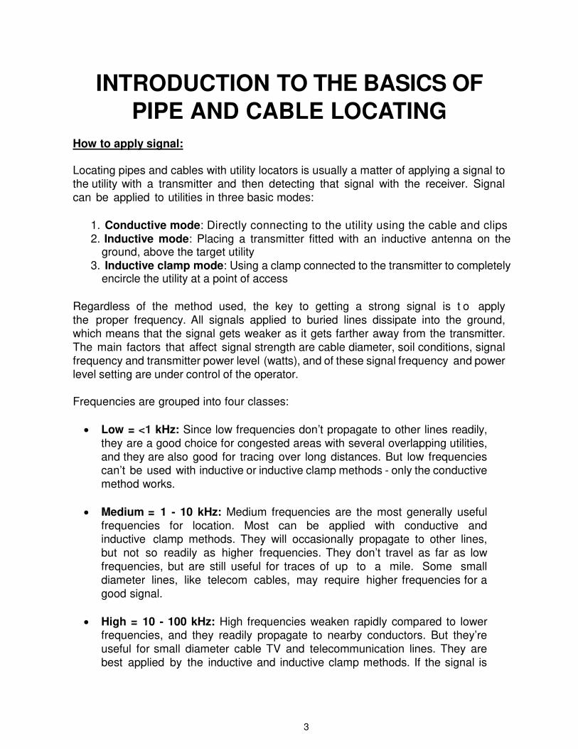
PIPE AND CABLE LOCATING How to apply signal: Locating pipes and cables with utility locators is usually a matter of applying a signal to the utility with a transmitter and then detecting that signal with the receiver. Signal
can be applied to utilities in three basic modes:
1. Conductive mode: Directly connecting to the utility using the cable and clips
2. Inductive mode: Placing a transmitter fitted with an inductive antenna on the ground, above the target utility
3. Inductive clamp mode: Using a clamp connected to the transmitter to completely encircle the utility at a point of access
Regardless of the method used, the key to getting a strong signal is t o apply the proper frequency. All signals applied to buried lines dissipate into the ground, which means that the signal gets weaker as it gets farther away from the transmitter. The main factors that affect signal strength are cable diameter, soil conditions, signal frequency and transmitter power level (watts), and of these signal frequency and power level setting are under control of the operator.
Frequencies are grouped into four classes:
• Low = <1 kHz: Since low frequencies don’t propagate to other lines readily,
they are a good choice for congested areas with several overlapping utilities, and they are also good for tracing over long distances. But low frequencies can’t be used with inductive or inductive clamp methods - only the conductive method works.
• Medium = 1 - 10 kHz: Medium frequencies are the most generally useful
frequencies for location. Most can be applied with conductive and inductive clamp methods. They will occasionally propagate to other lines, but not so readily as higher frequencies. They don’t travel as far as low
frequencies, but are still useful for traces of up to a mile. Some small
diameter lines, like telecom cables, may require higher frequencies for a good signal.
• High = 10 - 100 kHz: High frequencies weaken rapidly compared to lower
frequencies, and they readily propagate to nearby conductors. But they’re
useful for small diameter cable TV and telecommunication lines. They are
best applied by the inductive and inductive clamp methods. If the signal is

4
weak near the beginning of the trace, try a higher frequency.
• Very High = >100 kHz: Because they attenuate very quickly compared to lower frequencies, and because they easily propagate to other conductors,
Very High frequencies are a good way to rapidly sweep for all utilities in a
congested area. Very High frequencies will also give good signal across gaps in a line, such as insulated pipe joints or cable breaks.
Power levels:
High watts are beneficial to achieve long distances on small c onductors, such as electrical, telecommunication cables and tracer wires; to push through high
resistance conductors or to jump across non-conductive joints, such as ductile iron
pipes. High watts will propagate its energy to nearby or adjacent buried utilities. Choose a lower watt to minimize propagation.
Signal Application Methods:
Conductive: The conductive method means that a direct connection is made to the pipe or cable being located, and it isolates the signal to just one line. For a strong signal over a long distance and for minimal coupling to other conductors, low frequencies are best.
Proper grounding is important when using the conductive method: the better the
ground, the stronger the signal. The transmitter is electrically connected at one end; the signal travels along the desired line, goes to ground, and completes the circuit via the ground stake. A poor connection or ground will give a weak or non-
existent signal. The ground stake should be as far from the far-end ground as possible, and it should be well away from the trace path. In practice, this means
that extending the stake away from the probable trace path at 90º is usually the best option (see below illustration). If necessary, ground leads can be extended
with any insulated wire, and ground stakes can be reset after the actual trace path is discovered.
5
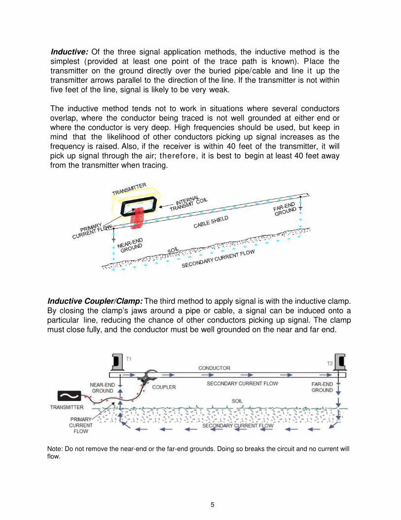
Inductive: Of the three signal application methods, the inductive method is the
simplest (provided at least one point of the trace path is known). Place the
transmitter on the ground directly over the buried pipe/cable and line it up the transmitter arrows parallel to the direction of the line. If the transmitter is not within
five feet of the line, signal is likely to be very weak.
The inductive method tends not to work in situations where several conductors
overlap, where the conductor being traced is not well grounded at either end or
where the conductor is very deep. High frequencies should be used, but keep in mind that the likelihood of other conductors picking up signal increases as the
frequency is raised. Also, if the receiver is within 40 feet of the transmitter, it will
pick up signal through the air; therefore, it is best to begin at least 40 feet away
from the transmitter when tracing.
Inductive Coupler/Clamp: The third method to apply signal is with the inductive clamp. By closing the clamp’s jaws around a pipe or cable, a signal can be induced onto a particular line, reducing the chance of other conductors picking up signal. The clamp must close fully, and the conductor must be well grounded on the near and far end.
Note: Do not remove the near-end or the far-end grounds. Doing so breaks the circuit and no current will flow.

6
Passive Power Frequencies: In Passive mode, the transmitter is not used. Instead, the receiver is used to search
for 50 or 60 Hz signals (like those produced by energized cable carrying AC power).
These are low frequencies, but they can still propagate to other nearby conductors. In passive mode, it is not possible to distinguish between conductors - the signal could be
coming from any grounded conductor, such as buried pipe or rebar. But knowing they
exist can be useful.
Energized power cables are easy to detect, except for those that have been designed
so that the ‘out’ and ‘return’ fields cancel each other (typically the case with appliance power cords). Cables like this, particularly three-phase cables, are hard to detect. One
trick that some receivers use is to detect an odd harmonic of 50 or 60 Hz.
Trace Mode: Several indicators help to zero in on the location of a pipe or cable. The receiver tone changes pitch and is highest when directly over the traced utility. Similarly, numeric strength indicators are also at a maximum w h e n directly over lines. Both these indicators rely on the receiver being in alignment with the cable path. If the path changes direction abruptly, display arrows can guide you back to the true path. If no arrows are visible on the display, the signal strength is too weak for detection and you will have to search using the receiver tone and numeric indicators. You may also try twisting the receiver to align the receiver with the cable path.
o Left Arrow: Move receiver to the left to get back on
trace path
o Right Arrow: Move receiver to the right to get back
on trace path
o Both Arrows & Bar: This signal, together with a
beeping sound, indicates that you are directly over the trace path
7
Adjusting the Gain: The gain setting determines how sensitive the receiver is to a signal, and is
therefore an important adjustment. If the gain is set too low, no signal will be detected;
if the gain is set too high, accuracy is reduced and tracing the wrong conductor is likely. With a Schonstedt locator, the gain can e i t h e r be set manually or automatically.
Set the gain with the receiver directly over the targeted line. You can use the gain
control’s numeric strength indicator as a guide. As a rule of thumb, the gain should be
set to the lowest setting that still shows a clear peak over the trace path. As you move
away from the transmitter, signal strength drops and you will have to adjust gain periodically.
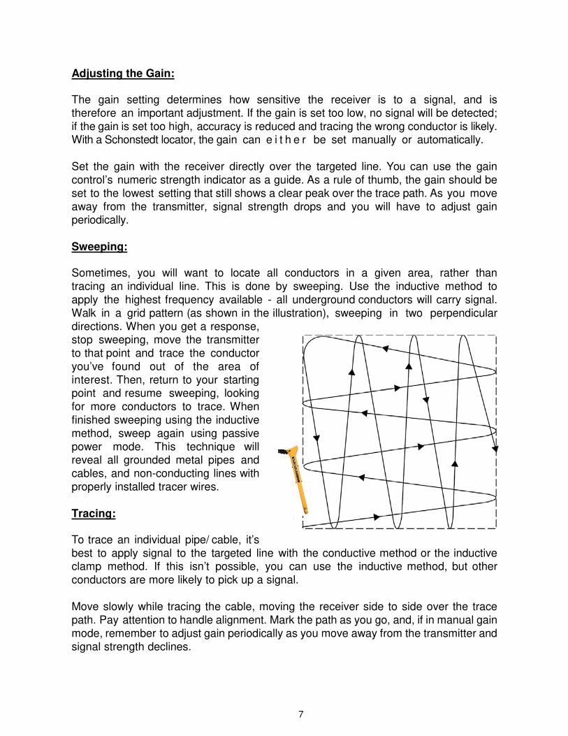
Sweeping: Sometimes, you will want to locate all conductors in a given area, rather than tracing an individual line. This is done by sweeping. Use the inductive method to apply the highest frequency available - all underground conductors will carry signal. Walk in a grid pattern (as shown in the illustration), sweeping in two perpendicular directions. When you get a response, stop sweeping, move the transmitter to that point and trace the conductor you’ve found out of the area of interest. Then, return to your starting point and resume sweeping, looking for more conductors to trace. When finished sweeping using the inductive method, sweep again using passive power mode. This technique will reveal all grounded metal pipes and
cables, and non-conducting lines with properly installed tracer wires.
Tracing: To trace an individual pipe/ cable, it’s best to apply signal to the targeted line with the conductive method or the inductive clamp method. If this isn’t possible, you can use the inductive method, but other conductors are more likely to pick up a signal.
Move slowly while tracing the cable, moving the receiver side to side over the trace
path. Pay attention to handle alignment. Mark the path as you go, and, if in manual gain
mode, remember to adjust gain periodically as you move away from the transmitter and signal strength declines.

8
Milliamp Display of Signal Strength: Measuring the current that flows into the utility helps to determine the quality of the connection and the potential for doing a good locate. The transmitter measures that
output current in the conductive mode only, in units of mA (milliamps). A reading of
30 to 40 mA generally indicates a good signal.
9
LOCATING A POWER CABLE
(Note: See Introduction for an explanation of 60 Hz locating) Applying Signal to Power Cables - Conductive Method: You can apply signal directly with the conductive clip in several different places, including the transformer, meter, and the targeted cable.
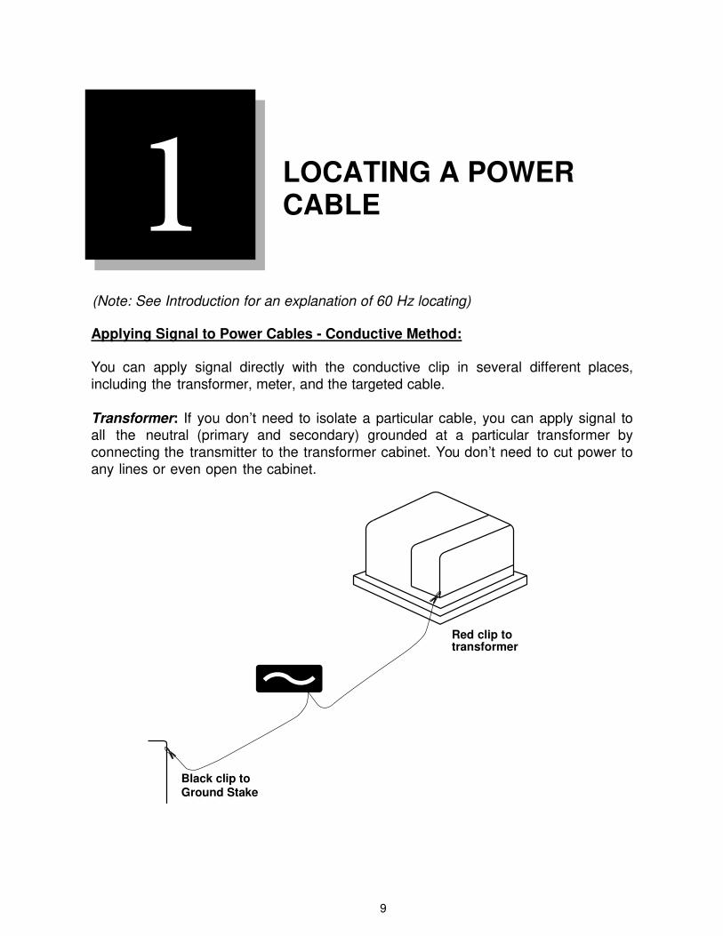
Transformer: If you don’t need to isolate a particular cable, you can apply signal to all the neutral (primary and secondary) grounded at a particular transformer by connecting the transmitter to the transformer cabinet. You don’t need to cut power to any lines or even open the cabinet.
1
Red clip to transformer
Black clip to Ground Stake

10
Meter: The secondary neutral is
grounded at both the transformer
and the meter, so secondary cables
can be traced by connecting the
transmitter directly to the meter’s metal box. Since typically the
transformer is better grounded than
the meter, you are likely to get a
better signal when connecting to the meter. Remember to place the
transmitter’s ground stake well
away from the meter - you may have
to extend it with insulated wire. This
is a fast, convenient signal application technique, as you don’t have to break the meter seal. Use the lowest frequency available, in order to minimize the propagation of signal to other lines in the area.
Ground stake and black clip: place as far away from meter as possible
Targeted Cable: If power has been cut to a cable, and the far end is grounded, you can attach the conductive clip directly to the targeted cable, thus isolating the cable. See illustration below.
Ground stake and black clip: place as far away from meter as possible, at right angles
to the cable path.
11
Applying Signal to Power Cables - Inductive Method:
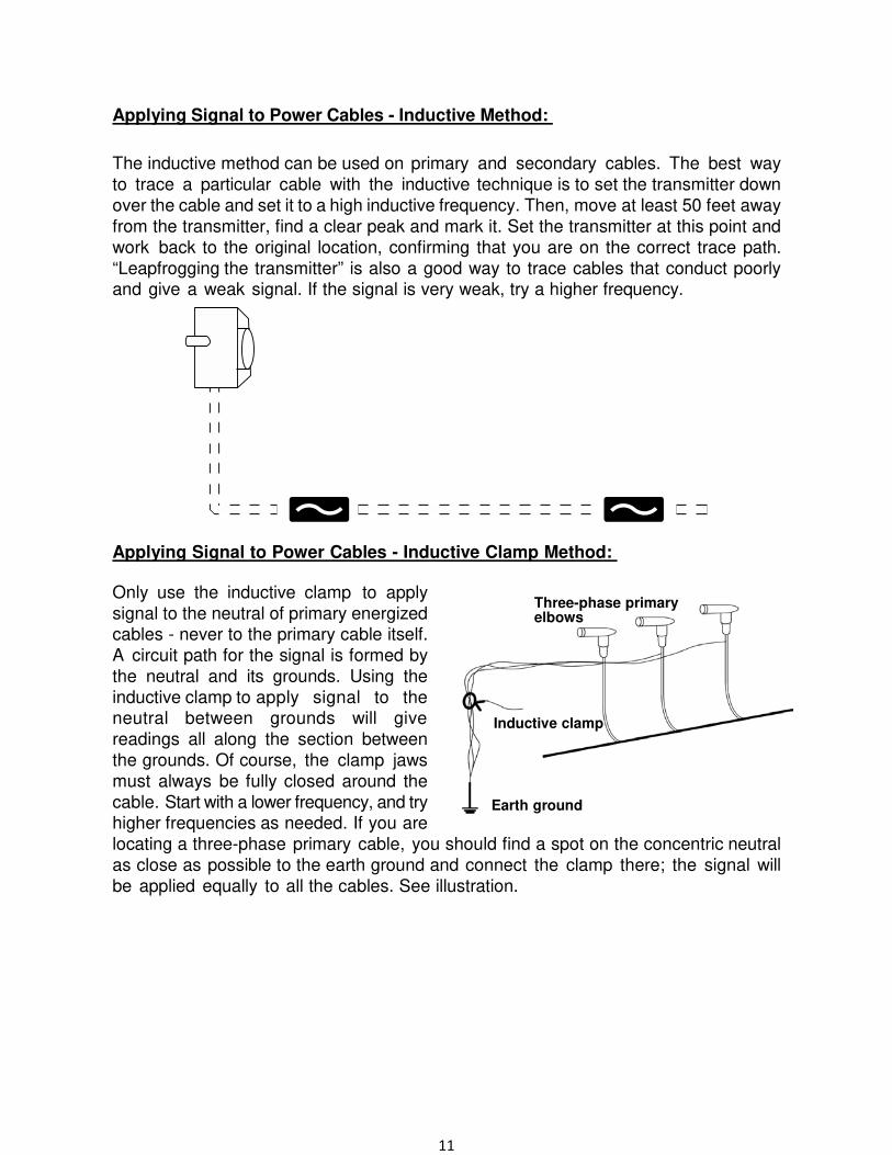
The inductive method can be used on primary and secondary cables. The best way
to trace a particular cable with the inductive technique is to set the transmitter down
over the cable and set it to a high inductive frequency. Then, move at least 50 feet away
from the transmitter, find a clear peak and mark it. Set the transmitter at this point and
work back to the original location, confirming that you are on the correct trace path.
“Leapfrogging the transmitter” is also a good way to trace cables that conduct poorly and give a weak signal. If the signal is very weak, try a higher frequency.
Applying Signal to Power Cables - Inductive Clamp Method: Only use the inductive clamp to apply signal to the neutral of primary energized cables - never to the primary cable itself. A circuit path for the signal is formed by the neutral and its grounds. Using the inductive clamp to apply signal to the neutral between grounds will give readings all along the section between the grounds. Of course, the clamp jaws must always be fully closed around the
cable. Start with a lower frequency, and try higher frequencies as needed. If you are
locating a three-phase primary cable, you should find a spot on the concentric neutral as close as possible to the earth ground and connect the clamp there; the signal will
be applied equally to all the cables. See illustration.
Three-phase primary elbows
Inductive clamp
Earth ground
12
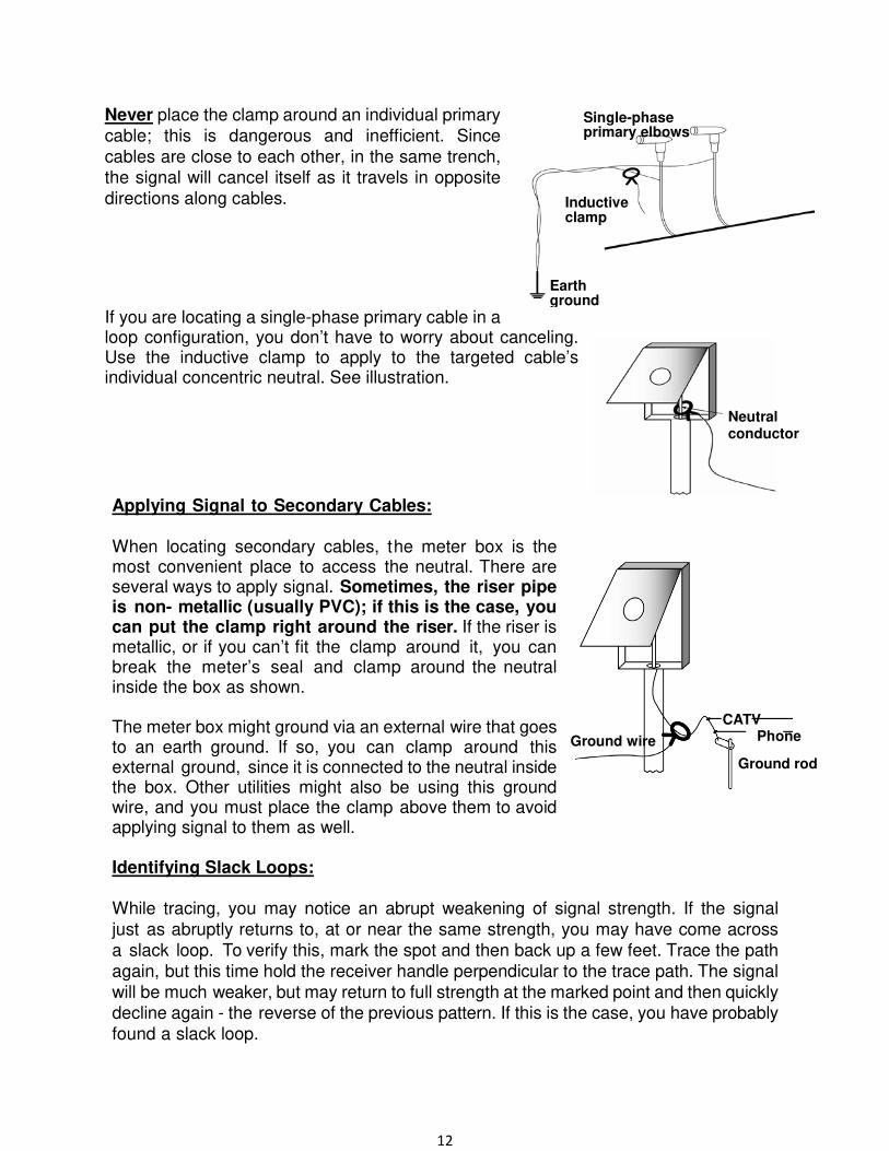
Never place the clamp around an individual primary
cable; this is dangerous and inefficient. Since
cables are close to each other, in the same trench, the signal will cancel itself as it travels in opposite
directions along cables.
If you are locating a single-phase primary cable in a loop configuration, you don’t have to worry about canceling. Use the inductive clamp to apply to the targeted cable’s individual concentric neutral. See illustration.
Applying Signal to Secondary Cables: When locating secondary cables, the meter box is the most convenient place to access the neutral. There are several ways to apply signal. Sometimes, the riser pipe is non- metallic (usually PVC); if this is the case, you can put the clamp right around the riser. If the riser is metallic, or if you can’t fit the clamp around it, you can break the meter’s seal and clamp around the neutral inside the box as shown.
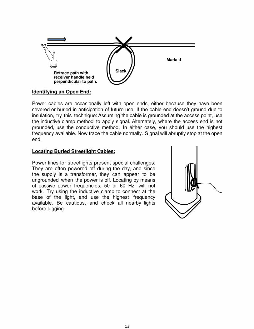
The meter box might ground via an external wire that goes to an earth ground. If so, you can clamp around this external ground, since it is connected to the neutral inside the box. Other utilities might also be using this ground wire, and you must place the clamp above them to avoid applying signal to them as well. Identifying Slack Loops: While tracing, you may notice an abrupt weakening of signal strength. If the signal
just as abruptly returns to, at or near the same strength, you may have come across a slack loop. To verify this, mark the spot and then back up a few feet. Trace the path
again, but this time hold the receiver handle perpendicular to the trace path. The signal
will be much weaker, but may return to full strength at the marked point and then quickly decline again - the reverse of the previous pattern. If this is the case, you have probably found a slack loop.
Neutral conductor
Single-phase primary elbows
Inductive clamp
Earth ground
CATV Phone Ground wire
Ground rod
13
Identifying an Open End:
Power cables are occasionally left with open ends, either because they have been
severed or buried in anticipation of future use. If the cable end doesn’t ground due to insulation, try this technique: Assuming the cable is grounded at the access point, use the inductive clamp method to apply signal. Alternately, where the access end is not grounded, use the conductive method. In either case, you should use the highest frequency available. Now trace the cable normally. Signal will abruptly stop at the open end.
Locating Buried Streetlight Cables: Power lines for streetlights present special challenges. They are often powered off during the day, and since the supply is a transformer, they can appear to be ungrounded when the power is off. Locating by means of passive power frequencies, 50 or 60 Hz, will not work. Try using the inductive clamp to connect at the base of the light, and use the highest frequency available. Be cautious, and check all nearby lights before digging.
Marked
Retrace path with receiver handle held perpendicular to path.
Slack
14
LOCATING PIPE
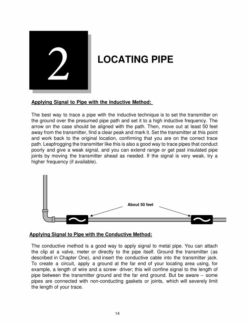
Applying Signal to Pipe with the Inductive Method:
The best way to trace a pipe with the inductive technique is to set the transmitter on the ground over the presumed pipe path and set it to a high inductive frequency. The arrow on the case should be aligned with the path. Then, move out at least 50 feet away from the transmitter, find a clear peak and mark it. Set the transmitter at this point and work back to the original location, confirming that you are on the correct trace path. Leapfrogging the transmitter like this is also a good way to trace pipes that conduct poorly and give a weak signal, and you can extend range or get past insulated pipe joints by moving the transmitter ahead as needed. If the signal is very weak, try a higher frequency (if available).
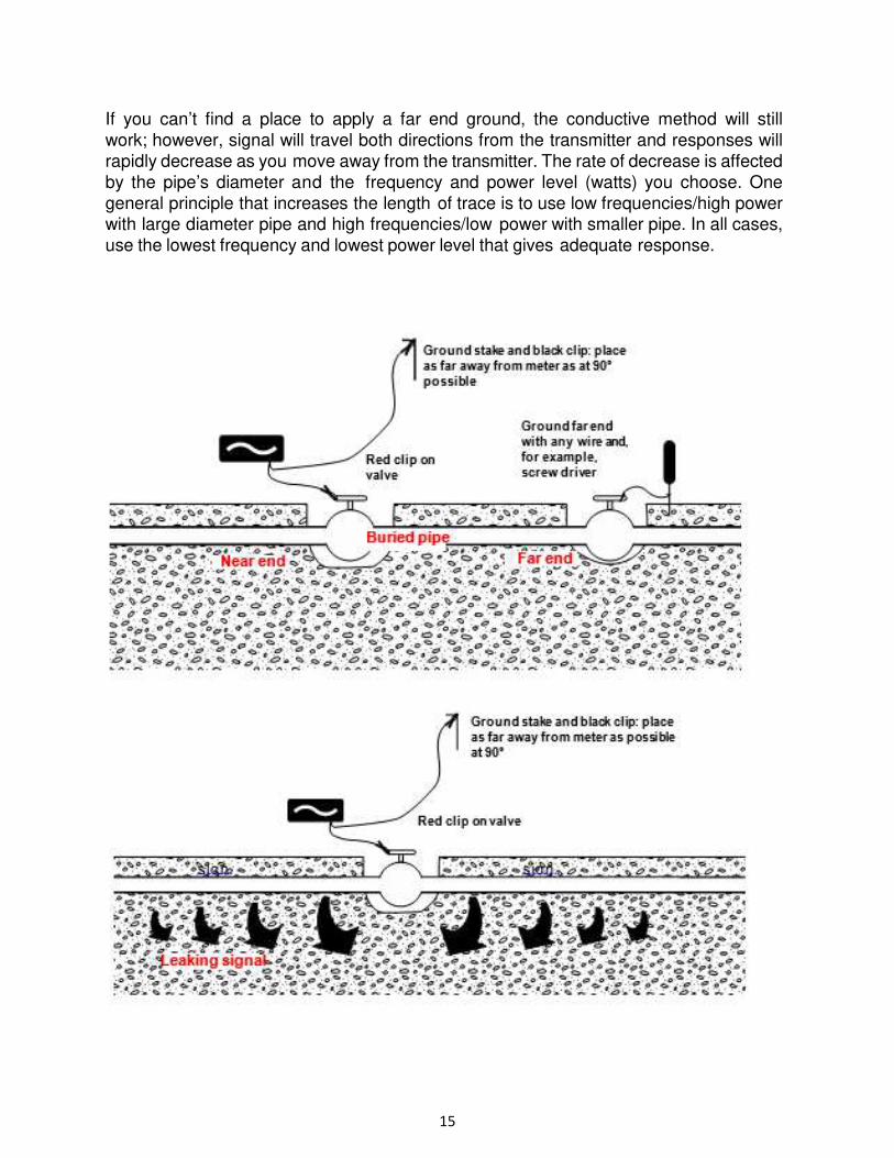
Applying Signal to Pipe with the Conductive Method: The conductive method is a good way to apply signal to metal pipe. You can attach
the clip at a valve, meter or directly to the pipe itself. Ground the transmitter (as
described in Chapter One), and insert the conductive cable into the transmitter jack. To create a circuit, apply a ground at the far end of your locating area using, for
example, a length of wire and a screw- driver; this will confine signal to the length of pipe between the transmitter ground and the far end ground. But be aware -- some
pipes are connected with non-conducting gaskets or joints, which will severely limit the length of your trace.
2
About 50 feet
15
If you can’t find a place to apply a far end ground, the conductive method will still
work; however, signal will travel both directions from the transmitter and responses will
rapidly decrease as you move away from the transmitter. The rate of decrease is affected
by the pipe’s diameter and the frequency and power level (watts) you choose. One
general principle that increases the length of trace is to use low frequencies/high power with large diameter pipe and high frequencies/low power with smaller pipe. In all cases,
use the lowest frequency and lowest power level that gives adequate response.
16
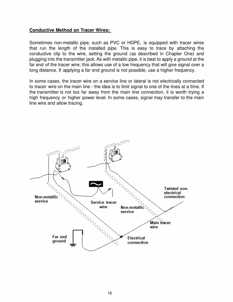
Conductive Method on Tracer Wires:
Sometimes non-metallic pipe, such as PVC or HDPE, is equipped with tracer wires
that run the length of the installed pipe. This is easy to trace by attaching the
conductive clip to the wire, setting the ground (as described in Chapter One) and
plugging into the transmitter jack. As with metallic pipe, it is best to apply a ground at the
far end of the tracer wire; this allows use of a low frequency that will give signal over a
long distance. If applying a far end ground is not possible, use a higher frequency.
In some cases, the tracer wire on a service line or lateral is not electrically connected
to tracer wire on the main line - the idea is to limit signal to one of the lines at a time. If
the transmitter is not too far away from the main line connection, it is worth trying a
high frequency or higher power level. In some cases, signal may transfer to the main
line wire and allow tracing.
17
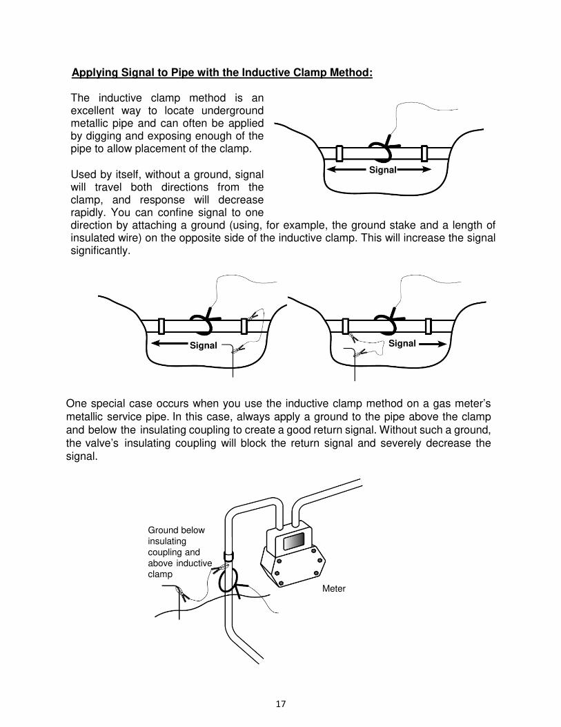
Applying Signal to Pipe with the Inductive Clamp Method:
The inductive clamp method is an excellent way to locate underground metallic pipe and can often be applied by digging and exposing enough of the pipe to allow placement of the clamp.
Used by itself, without a ground, signal will travel both directions from the clamp, and response will decrease rapidly. You can confine signal to one direction by attaching a ground (using, for example, the ground stake and a length of insulated wire) on the opposite side of the inductive clamp. This will increase the signal significantly.
One special case occurs when you use the inductive clamp method on a gas meter’s metallic service pipe. In this case, always apply a ground to the pipe above the clamp and below the insulating coupling to create a good return signal. Without such a ground, the valve’s insulating coupling will block the return signal and severely decrease the signal.
Ground below
insulating
coupling and
above inductive clamp
Meter
Signal Signal
Signal
18
LOCATING TELEPHONE CABLE
Applying Signal to Telephone Cables:
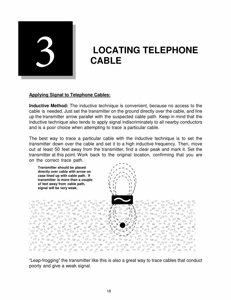
Inductive Method: The inductive technique is convenient, because no access to the cable is needed. Just set the transmitter on the ground directly over the cable, and line up the transmitter arrow parallel with the suspected cable path. Keep in mind that the inductive technique also tends to apply signal indiscriminately to all nearby conductors and is a poor choice when attempting to trace a particular cable.
The best way to trace a particular cable with the inductive technique is to set the transmitter down over the cable and set it to a high inductive frequency. Then, move out at least 50 feet away from the transmitter, find a clear peak and mark it. Set the transmitter at this point. Work back to the original location, confirming that you are on the correct trace path.
“Leap-frogging” the transmitter like this is also a great way to trace cables that conduct
poorly and give a weak signal.
Transmitter should be placed directly over cable with arrow on case lined up with cable path. If transmitter is more than a couple of feet away from cable path, signal will be very weak.
3
19
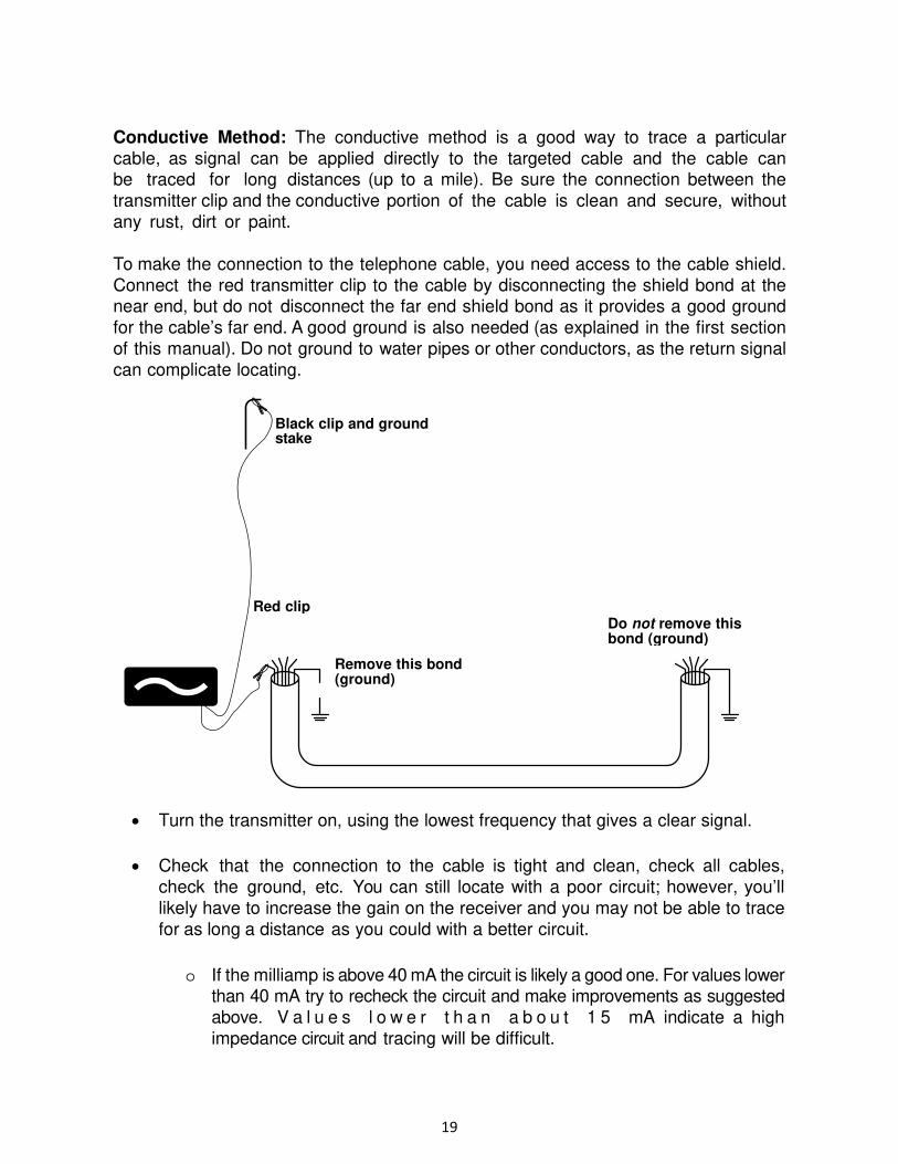
Conductive Method: The conductive method is a good way to trace a particular
cable, as signal can be applied directly to the targeted cable and the cable can be traced for long distances (up to a mile). Be sure the connection between the
transmitter clip and the conductive portion of the cable is clean and secure, without
any rust, dirt or paint.
To make the connection to the telephone cable, you need access to the cable shield.
Connect the red transmitter clip to the cable by disconnecting the shield bond at the near end, but do not disconnect the far end shield bond as it provides a good ground
for the cable’s far end. A good ground is also needed (as explained in the first section
of this manual). Do not ground to water pipes or other conductors, as the return signal
can complicate locating.
• Turn the transmitter on, using the lowest frequency that gives a clear signal.
• Check that the connection to the cable is tight and clean, check all cables,check the ground, etc. You can still locate with a poor circuit; however, you’ll
likely have to increase the gain on the receiver and you may not be able to tracefor as long a distance as you could with a better circuit.
o If the milliamp is above 40 mA the circuit is likely a good one. For values lowerthan 40 mA try to recheck the circuit and make improvements as suggested
above. V a l u e s l o w e r t h a n a b o u t 1 5 mA indicate a highimpedance circuit and tracing will be difficult.
Black clip and ground stake
Red clipDo not remove this bond (ground)
Remove this bond (ground)
20
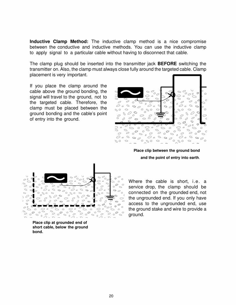
Inductive Clamp Method: The inductive clamp method is a nice compromise
between the conductive and inductive methods. You can use the inductive clamp
to apply signal to a particular cable without having to disconnect that cable.
The clamp plug should be inserted into the transmitter jack BEFORE switching the transmitter on. Also, the clamp must always close fully around the targeted cable. Clamp
placement is very important.
If you place the clamp around the
cable above the ground bonding, the
signal will travel to the ground, not to the targeted cable. Therefore, the clamp must be placed between the ground bonding and the cable’s point of entry into the ground.
Place clip between the ground bond
and the point of entry into earth.
Where the cable is short, i .e . a service drop, the clamp should be connected on the grounded end, not the ungrounded end. If you only have
access to the ungrounded end, use the ground stake and wire to provide a ground.
Place clip at grounded end of short cable, below the ground
bond.
21
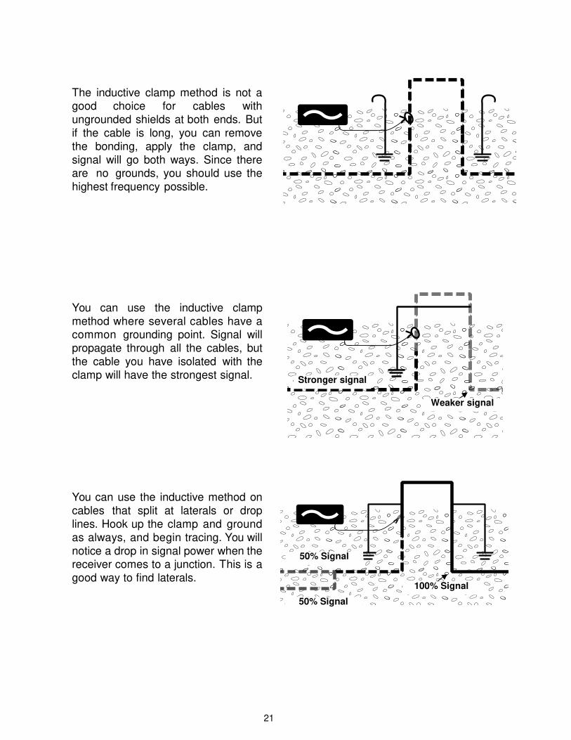
The inductive clamp method is not a good choice for cables with
ungrounded shields at both ends. But
if the cable is long, you can remove
the bonding, apply the clamp, and
signal will go both ways. Since there are no grounds, you should use the
highest frequency possible.
You can use the inductive clamp method where several cables have a common grounding point. Signal will propagate through all the cables, but the cable you have isolated with the clamp will have the strongest signal.
You can use the inductive method on cables that split at laterals or drop lines. Hook up the clamp and ground
as always, and begin tracing. You will
notice a drop in signal power when the receiver comes to a junction. This is a good way to find laterals.
Stronger signal
Weaker signal
50% Signal
50% Signal
100% Signal
22
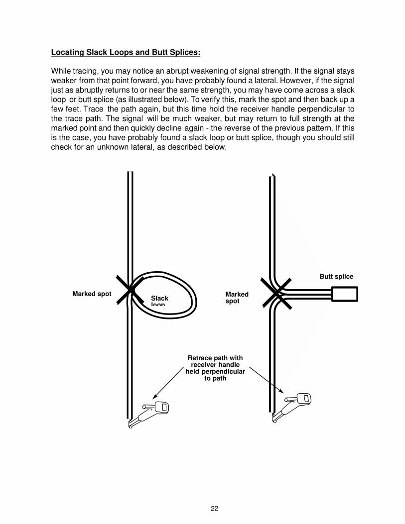
Locating Slack Loops and Butt Splices:
While tracing, you may notice an abrupt weakening of signal strength. If the signal stays
weaker from that point forward, you have probably found a lateral. However, if the signal
just as abruptly returns to or near the same strength, you may have come across a slack loop or butt splice (as illustrated below). To verify this, mark the spot and then back up a
few feet. Trace the path again, but this time hold the receiver handle perpendicular to
the trace path. The signal will be much weaker, but may return to full strength at the
marked point and then quickly decline again - the reverse of the previous pattern. If this is the case, you have probably found a slack loop or butt splice, though you should still
check for an unknown lateral, as described below.
Marked spot
Butt splice
Slack loop
Marked spot
Retrace path with receiver handle
held perpendicular to path
23
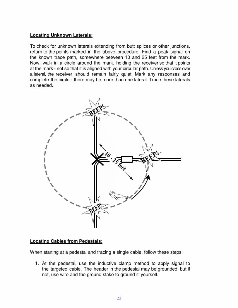
Locating Unknown Laterals:
To check for unknown laterals extending from butt splices or other junctions,
return to the points marked in the above procedure. Find a peak signal on the known trace path, somewhere between 10 and 25 feet from the mark.
Now, walk in a circle around the mark, holding the receiver so that it points
at the mark - not so that it is aligned with your circular path. Unless you cross over
a lateral, the receiver should remain fairly quiet. Mark any responses and complete the circle - there may be more than one lateral. Trace these laterals
as needed.
Locating Cables from Pedestals:
When starting at a pedestal and tracing a single cable, follow these steps:
1. At the pedestal, use the inductive clamp method to apply signal to
the targeted cable. The header in the pedestal may be grounded, but ifnot, use wire and the ground stake to ground it yourself.
24
Pedestal
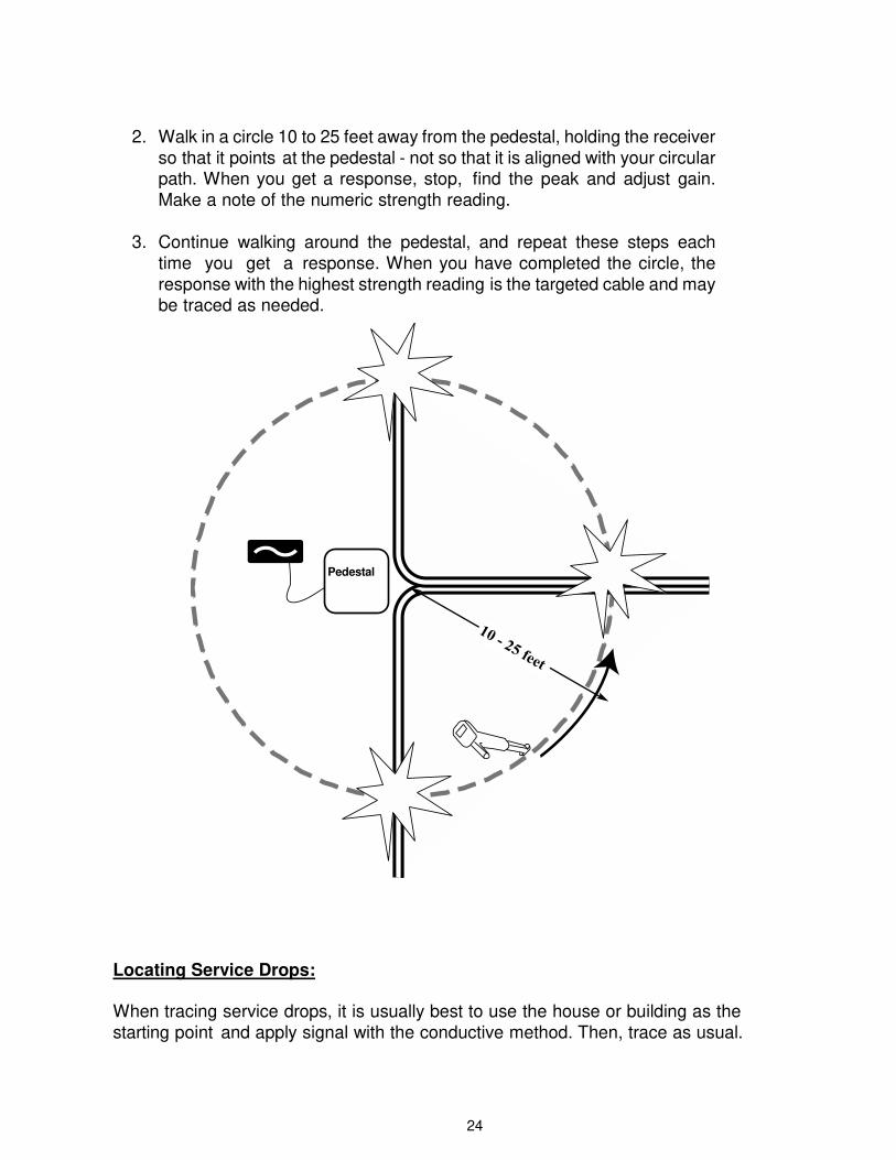
2. Walk in a circle 10 to 25 feet away from the pedestal, holding the receiver
so that it points at the pedestal - not so that it is aligned with your circularpath. When you get a response, stop, find the peak and adjust gain.
Make a note of the numeric strength reading.
3. Continue walking around the pedestal, and repeat these steps each
time you get a response. When you have completed the circle, the
response with the highest strength reading is the targeted cable and maybe traced as needed.
Locating Service Drops:
When tracing service drops, it is usually best to use the house or building as the starting point and apply signal with the conductive method. Then, trace as usual.

25
Locating an Open End:
Follow these steps to locate a cable with an unterminated or open end:
1. Where the cable is bonded to ground at the starting point, use the inductive
clamp method to apply signal.
2. If the cable is not bonded to ground, use the conductive method.
3. In either case, use the highest frequency possible. Trace as usual; theresponse will drop off abruptly at the break or open end.
Locating Fiber Optic: Can Fiber Optic Cable be traced?
Optical fibers in themselves can’t be traced with a utility locator - they are not conductors. However, typically one of several types of conductor is included with the fiber optic cable. This might be a metallic sheath around the fiber, a metallic wire woven into the sheath (for strength and locating) or an insulated wire may have been pulled through the same duct as the fiber. If none of these are present, you will have to use site plans or Ground Penetrating Radar.
Underground fiber optic cable is usually installed in a duct or in a tube run through a large duct. Typically the cable is run from a central office to a remote terminal office, and there may be several splice points along the way, accessed by manholes or hand holes. Where good practices are followed, the metallic sheath or woven wire will be grounded at both ends. Particular grounding policies vary by company, and you should make no automatic assumptions. Sometimes grounding is via remotely actuated relay or voltage transient suppression device.
In some cases, fiber optic installations have their own rack-mounted transmitter that can apply signal selectively. If this transmitter applies a 512 Hz and your receiver has a 512 Hz mode (the sonde mode), then the cable can be traced using the installation’s transmitter and your receiver.
Attaching at a Central or Remote Office:
If there is no installed transmitter or if it doesn’t match up with your receiver, you can still apply signal at the central or remote office using your transmitter and the conductive method.
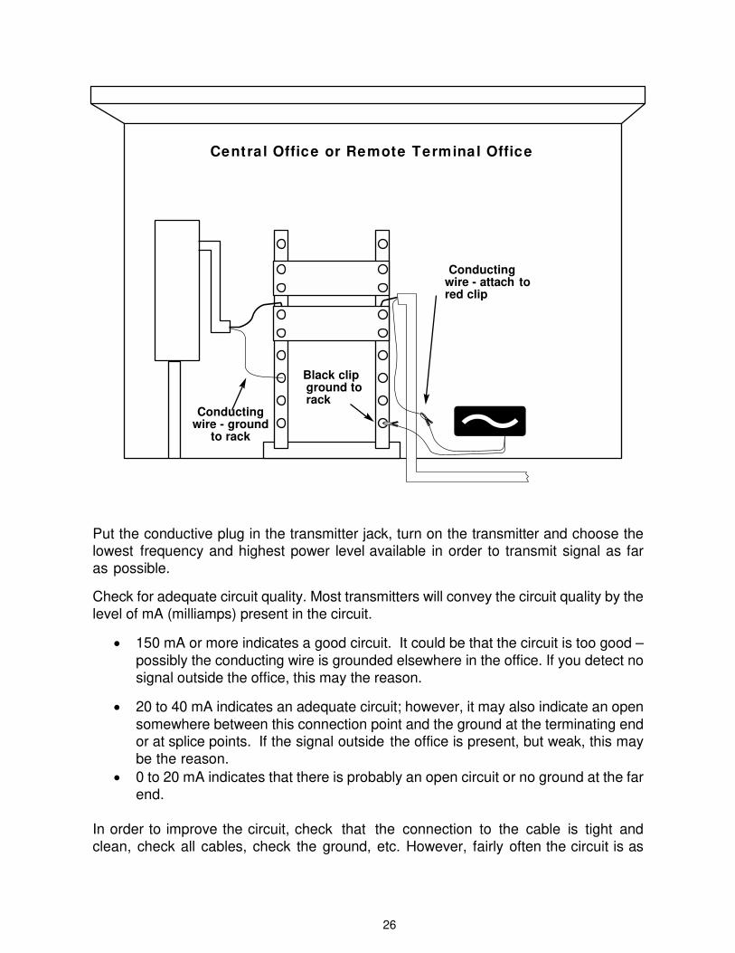
To attach the clip, find the ground point for the fiber optic cable’s conducting wire; this is usually near the rack mounted digital conversion equipment. Disconnect the wire. Connect your transmitter to it and to the ground point (see illustration below).
26
Put the conductive plug in the transmitter jack, turn on the transmitter and choose the lowest frequency and highest power level available in order to transmit signal as far as possible.
Check for adequate circuit quality. Most transmitters will convey the circuit quality by the level of mA (milliamps) present in the circuit.
• 150 mA or more indicates a good circuit. It could be that the circuit is too good –
possibly the conducting wire is grounded elsewhere in the office. If you detect nosignal outside the office, this may the reason.
• 20 to 40 mA indicates an adequate circuit; however, it may also indicate an open
somewhere between this connection point and the ground at the terminating endor at splice points. If the signal outside the office is present, but weak, this maybe the reason.
• 0 to 20 mA indicates that there is probably an open circuit or no ground at the far
end.
In order to improve the circuit, check that the connection to the cable is tight and
clean, check all cables, check the ground, etc. However, fairly often the circuit is as
Central Office or Remote Terminal Office
Conducting wire - attach to red clip
Black clip ground torack
Conducting wire - ground
to rack
27
good as it’s going to get. You can still locate with a poor circuit, but you’ll probably have
to increase receiver gain and you may not be able to trace for as long a distance as you
could with a better circuit.
Attaching at a Splice Point:
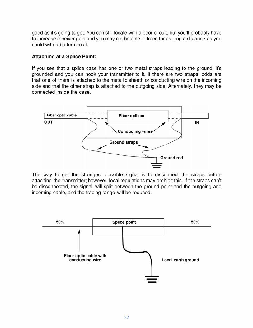
If you see that a splice case has one or two metal straps leading to the ground, it’s grounded and you can hook your transmitter to it. If there are two straps, odds are
that one of them is attached to the metallic sheath or conducting wire on the incoming
side and that the other strap is attached to the outgoing side. Alternately, they may be
connected inside the case.
The way to get the strongest possible signal is to disconnect the straps before attaching the transmitter; however, local regulations may prohibit this. If the straps can’t be disconnected, the signal will split between the ground point and the outgoing and incoming cable, and the tracing range will be reduced.
50% Splice point 50%
Fiber optic cable with conducting wire Local earth ground
Fiber optic cable
OUT
Fiber splices
IN
Conducting wires
Ground straps
Ground rod
28
Tracing Fiber Optic Cable:
If you are starting from a central or remote office, start outside the building wherever
you expect the cable to exit. Search until you get a response.
When starting from a manhole or hand hole, circle the hole with the receiver pointed toward the hole. When you get a response, find the peak, mark the point and begin
tracing. When you trace the cable over a long distance, the signal strength will eventually
decrease. This is because the signal bleeds off due to capacitance, or because
you pass additional grounds at splice points. Reduction by bleeding off is gradual, and reduction at ground points is abrupt. In either case, try to adjust the gain or
increase the power level.
LOCATING CATV CABLE
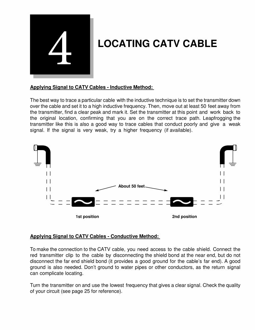
Applying Signal to CATV Cables - Inductive Method:
The best way to trace a particular cable with the inductive technique is to set the transmitter down
over the cable and set it to a high inductive frequency. Then, move out at least 50 feet away from the transmitter, find a clear peak and mark it. Set the transmitter at this point and work back to the original location, confirming that you are on the correct trace path. Leapfrogging the transmitter like this is also a good way to trace cables that conduct poorly and give a weak signal. If the signal is very weak, try a higher frequency (if available).
1st position 2nd position
Applying Signal to CATV Cables - Conductive Method:
To make the connection to the CATV cable, you need access to the cable shield. Connect the red transmitter clip to the cable by disconnecting the shield bond at the near end, but do not disconnect the far end shield bond (it provides a good ground for the cable’s far end). A good
ground is also needed. Don’t ground to water pipes or other conductors, as the return signal can complicate locating.
Turn the transmitter on and use the lowest frequency that gives a clear signal. Check the quality of your circuit (see page 25 for reference).
4
About 50 feet
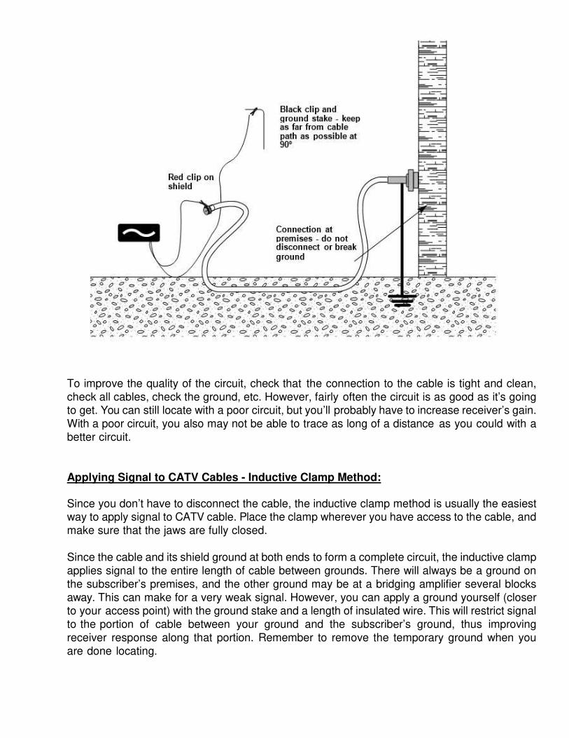
To improve the quality of the circuit, check that the connection to the cable is tight and clean, check all cables, check the ground, etc. However, fairly often the circuit is as good as it’s going to get. You can still locate with a poor circuit, but you’ll probably have to increase receiver’s gain. With a poor circuit, you also may not be able to trace as long of a distance as you could with a better circuit.
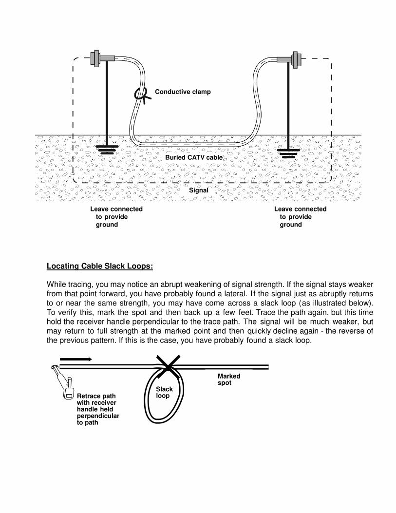
Applying Signal to CATV Cables - Inductive Clamp Method:
Since you don’t have to disconnect the cable, the inductive clamp method is usually the easiest way to apply signal to CATV cable. Place the clamp wherever you have access to the cable, and
make sure that the jaws are fully closed.
Since the cable and its shield ground at both ends to form a complete circuit, the inductive clamp applies signal to the entire length of cable between grounds. There will always be a ground on
the subscriber’s premises, and the other ground may be at a bridging amplifier several blocks
away. This can make for a very weak signal. However, you can apply a ground yourself (closer to your access point) with the ground stake and a length of insulated wire. This will restrict signal to the portion of cable between your ground and the subscriber’s ground, thus improving
receiver response along that portion. Remember to remove the temporary ground when you
are done locating.
Black clip and ground stake - keep as far from cable path as possible at 90º
Red clip on shield
Connection at premises - do not disconnect or break ground
Leave connected
to provide
ground
Leave connected
to provide
ground
Locating Cable Slack Loops:
While tracing, you may notice an abrupt weakening of signal strength. If the signal stays weaker from that point forward, you have probably found a lateral. I f the signal just as abruptly returns to or near the same strength, you may have come across a slack loop (as illustrated below). To verify this, mark the spot and then back up a few feet. Trace the path again, but this time hold the receiver handle perpendicular to the trace path. The signal will be much weaker, but may return to full strength at the marked point and then quickly decline again - the reverse of the previous pattern. If this is the case, you have probably found a slack loop.
Marked spot
Retrace path with receiver handle held perpendicular to path
Slack loop
Conductive clamp
Buried CATV cable
Signal

32
Locating CATV Cables from Pedestals:
When starting at a pedestal and tracing a single cable,
follow these steps:
1. At the pedestal, use the inductive clamp method toapply signal to the targeted cable. There may be
several cables fanning out from the pedestal, and
signal will probably propagate to all of them ( evenwhen using the clamp). However, the targeted cable,
the one you enclose with the clamp, will have an
obviously stronger signal.
2. The header in the pedestal may be grounded, but if not,use wire and the ground stake to ground it yourself.This strengthens receiver response by limiting signalto a shorter portion of cable.
3. Now, walk in a circle 10 to 25 feet away from the pedestal, holding the receiver so
that it points at the pedestal (not so that it aligns with your circular path). When you
get a response, stop, find the peak and adjust the gain. Make a note of the numeric
strength reading. Continue walking around the pedestal and repeat these steps
each time you get a response. When you have completed the circle, the response
with the highest strength reading is the targeted cable and may be traced as
needed.
Buried
Feeder
10 -25 feet
Weak Signal
Inductive
Clamp
Strong
Signal
33
SONDE LOCATING
Sondes, also referred to as transmitting beacons, are battery operated devices for
specific applications to detect various constructed material pipes (either metallic or non-metallic). The sonde emits a particular frequency utilized to achieve best results. Sondes in the Hertz (Hz) range are beneficial for deeper applications (from 8 to 15 feet) and are capable of signal penetration through dense pipe materials, such as steel, cement and clay tile pipes. Sondes in the kilohertz (kHz) range are best used for shallow depths ( from 1 to 8 feet) and are generally detected through lighter dense pipe materials, such as plastic pipes. A sondes performance will be adversely affected if the battery charge is weak.
Sonde Detection:
The pipe & cable locator receiver must have a frequency selection that identically matches the frequency and modulation of the sonde being detected.
Searching for the Sonde:
Due to the nature and strength of the sondes signal, it is necessary to have a general
idea of where the sonde is. Narrow the search area to a circle of several feet that is centered at the sonde. This is usually not much of a problem, since the sonde is "guided" by a device under control of the work crew. Once in the surroundings of the sonde, it
is important to differentiate whether you are positioned along the axis of the sonde (the direction of the pipe) or off to either side. In the sonde mode the directional arrows on
a locator are not functional, so the signal strength is the only indication available, and it will be "null" (very close to zero) if the receiver is placed on the axis of the sonde
with the plane of the sensors perpendicular to it. Rotate the locator's axis and the direction that results in increasing signal strength. Rotate the receiver back and forth
and move in the direction that produces the maximum signal strength. As the receiver gets closer to the sonde the signal strength increases to a maximum when directly over the sonde. The plane of the sensors will be directly parallel to the axis of the sonde at
this time.
5
34
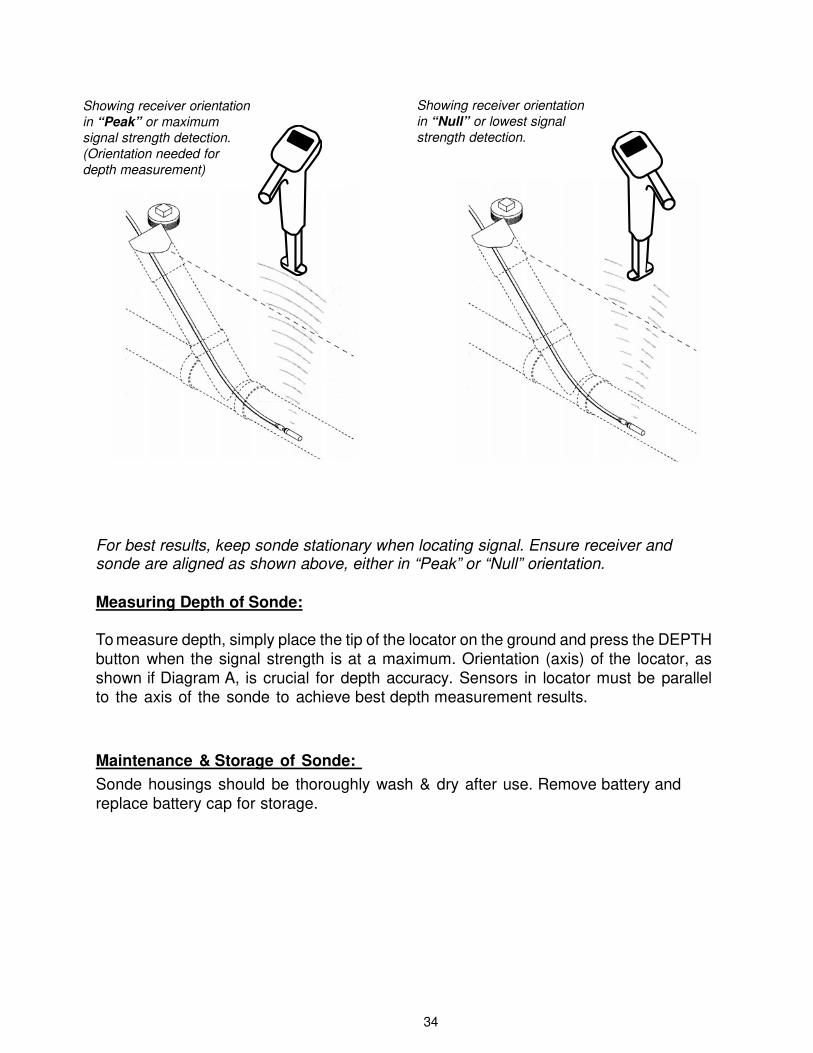
Showing receiver orientation
in “Peak” or maximum
signal strength detection.
(Orientation needed for
depth measurement)
Showing receiver orientation
in “Null” or lowest signal
strength detection.
For best results, keep sonde stationary when locating signal. Ensure receiver and sonde are aligned as shown above, either in “Peak” or “Null” orientation.
Measuring Depth of Sonde:
To measure depth, simply place the tip of the locator on the ground and press the DEPTH button when the signal strength is at a maximum. Orientation (axis) of the locator, as shown if Diagram A, is crucial for depth accuracy. Sensors in locator must be parallel to the axis of the sonde to achieve best depth measurement results.
Maintenance & Storage of Sonde:
Sonde housings should be thoroughly wash & dry after use. Remove battery and
replace battery cap for storage.
35
MAGNETIC LOCATING
Theory of Operation:
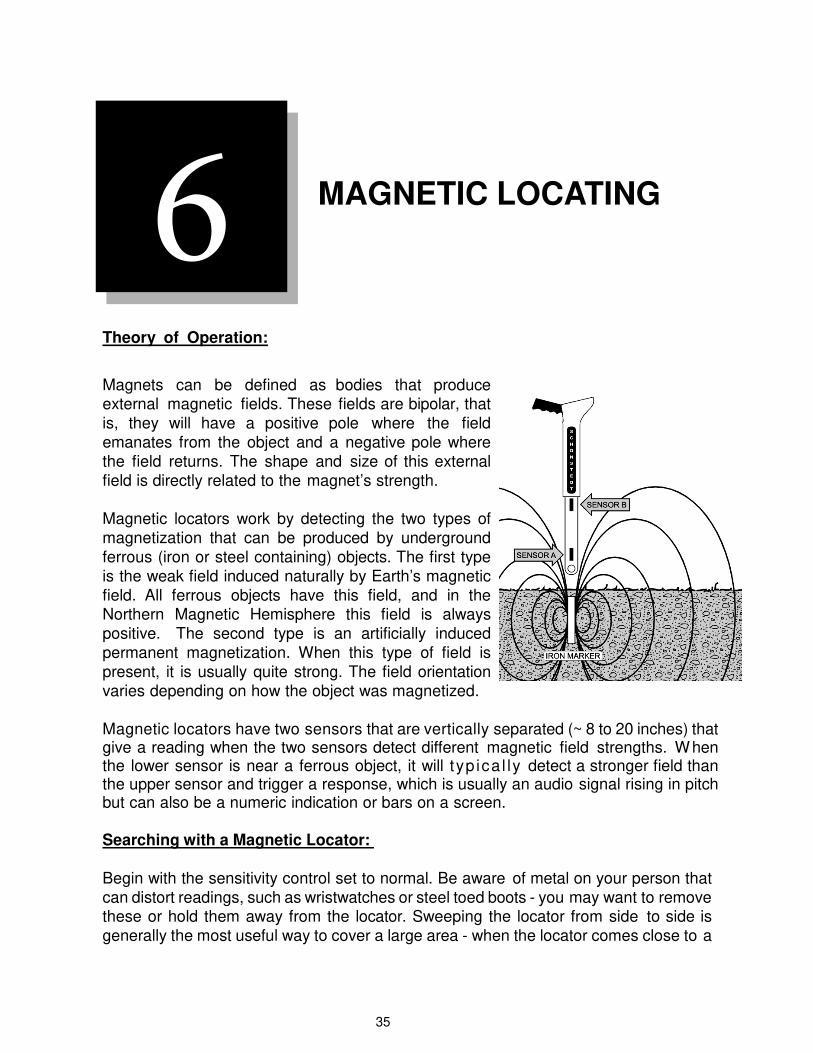
Magnets can be defined as bodies that produce external magnetic fields. These fields are bipolar, that is, they will have a positive pole where the field emanates from the object and a negative pole where the field returns. The shape and size of this external field is directly related to the magnet’s strength.
Magnetic locators work by detecting the two types of magnetization that can be produced by underground ferrous (iron or steel containing) objects. The first type is the weak field induced naturally by Earth’s magnetic field. All ferrous objects have this field, and in the Northern Magnetic Hemisphere this field is always positive. The second type is an artificially induced permanent magnetization. When this type of field is present, it is usually quite strong. The field orientation varies depending on how the object was magnetized.
Magnetic locators have two sensors that are vertically separated (~ 8 to 20 inches) that give a reading when the two sensors detect different magnetic field strengths. When the lower sensor is near a ferrous object, it will typ ica l ly detect a stronger field than the upper sensor and trigger a response, which is usually an audio signal rising in pitch but can also be a numeric indication or bars on a screen.
Searching with a Magnetic Locator:
Begin with the sensitivity control set to normal. Be aware of metal on your person that
can distort readings, such as wristwatches or steel toed boots - you may want to remove these or hold them away from the locator. Sweeping the locator from side to side is
generally the most useful way to cover a large area - when the locator comes close to a
6
36
ferrous object you will get a response.
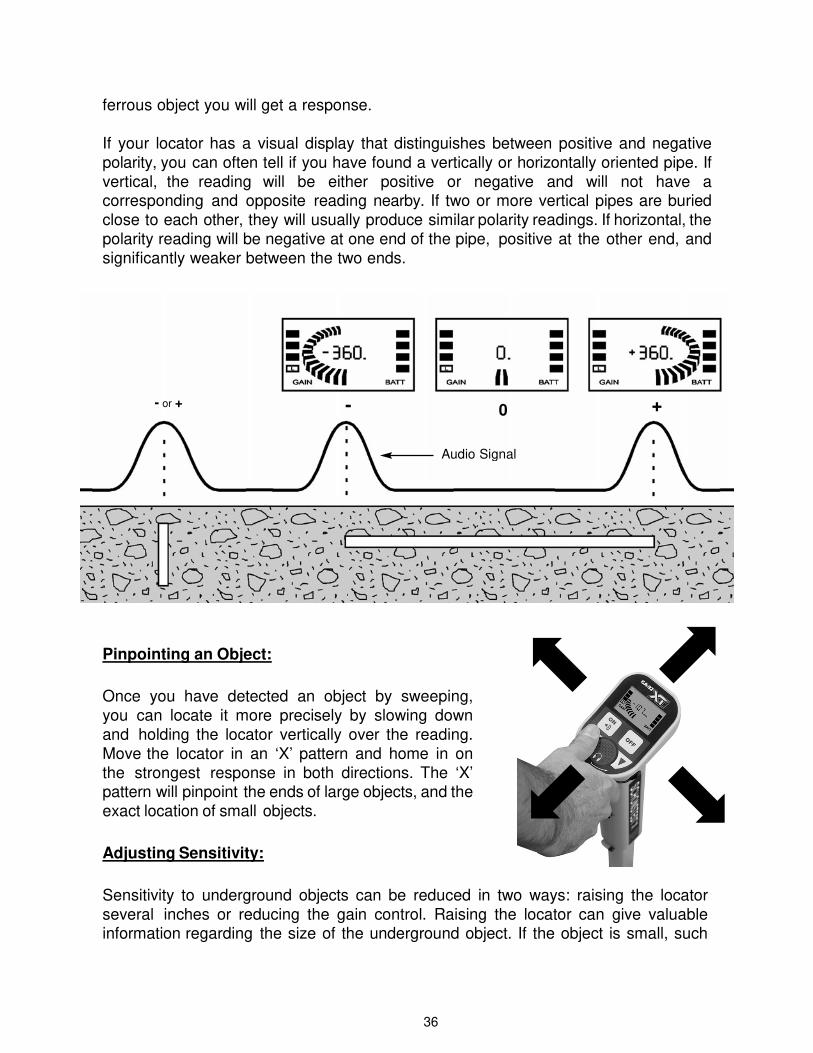
If your locator has a visual display that distinguishes between positive and negative
polarity, you can often tell if you have found a vertically or horizontally oriented pipe. If
vertical, the reading will be either positive or negative and will not have a corresponding and opposite reading nearby. If two or more vertical pipes are buried
close to each other, they will usually produce similar polarity readings. If horizontal, the
polarity reading will be negative at one end of the pipe, positive at the other end, and
significantly weaker between the two ends.
Pinpointing an Object:
Once you have detected an object by sweeping,
you can locate it more precisely by slowing down and holding the locator vertically over the reading. Move the locator in an ‘X’ pattern and home in on
the strongest response in both directions. The ‘X’ pattern will pinpoint the ends of large objects, and the
exact location of small objects.
Adjusting Sensitivity:
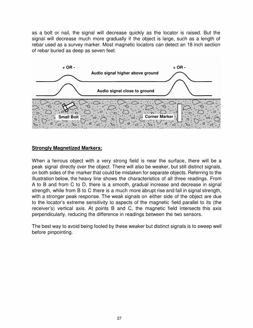
Sensitivity to underground objects can be reduced in two ways: raising the locator several inches or reducing the gain control. Raising the locator can give valuable information regarding the size of the underground object. If the object is small, such
- or + - 0 +
Audio Signal
37
as a bolt or nail, the signal will decrease quickly as the locator is raised. But the
signal will decrease much more gradually if the object is large, such as a length of
rebar used as a survey marker. Most magnetic locators can detect an 18 inch section of rebar buried as deep as seven feet.
Strongly Magnetized Markers:
When a ferrous object with a very strong field is near the surface, there will be a peak signal directly over the object. There will also be weaker, but still distinct signals, on both sides of the marker that could be mistaken for separate objects. Referring to the illustration below, the heavy line shows the characteristics of all three readings. From A to B and from C to D, there is a smooth, gradual increase and decrease in signal strength, while from B to C there is a much more abrupt rise and fall in signal strength, with a stronger peak response. The weak signals on either side of the object are due to the locator’s extreme sensitivity to aspects of the magnetic field parallel to its (the receiver’s) vertical axis. At points B and C, the magnetic field intersects this axis
perpendicularly, reducing the difference in readings between the two sensors.
The best way to avoid being fooled by these weaker but distinct signals is to sweep well before pinpointing.
+ OR - + OR -
Audio signal higher above ground
Audio signal close to ground
Small Bolt Corner Marker

38
How to Search Near a Chain Link Fence:
To search near a chain link fence, reduce the gain setting and hold the locator horizontally, with its long axis at right angles to the fence - this keeps the ‘upper’ sensor away from the
fence. Search by sweeping the locator
side to side, as well as forward and back. By this means, you can search a swath several feet wide along the base of the fence.
When the ‘lower’ sensor - which is a few inches from the end of the locator and should be the sensor closest to
the fence - is directly over a ferrous
object there will be a sudden drop in signal strength. As you move the lower sensor away from the object, response will rise just as abruptly.
AUDIO SIGNAL
B0
C0
A + OR -
+ OR -
D + OR -
IRON PIPE

39
Locating Metallic Pipe:
Long ferrous objects, such as pipe, have magnetic fields that reach out beyond their ends. In the case of metallic pipe, this even applies to pipe sections that have been welded together - there will be peak readings at the welded joints.
Signal Null with locator as shown
1- 5/8
+ or - 1- 1.5
FEET + or -
40
When tracing pipe, set the gain at maximum and hold the locator between one
and two feet above ground level. Holding the locator steady, walk along the
suspected pipe’s path, making temporary marks at any readings - don’t try to
pinpoint yet. When you have several marks in your area of concern, reduce the
gain for a second pass and hold the locator closer to the ground, pinpointing the peak response near the previously marked points. These marks at peak
response will reveal the pipe’s location. Magnetic locators can get a signal from
four inch pipe set as deep as eight feet.
How to Locate in Cluttered Areas:
One approach to searching in cluttered areas is to sharply reduce the locator’s
sensitivity before sweeping. The locator will not detect smaller objects, but will still respond to larger objects. To find very large objects, such as steel cisterns or tanks, you can raise the locator several feet above ground level. Small objects near the surface will not be detected, but deep, very large objects will.
When locating rebar in concrete, keep in mind that readings will be strongest at rebar ends, but also consider that steel ties at rebar intersections will also give strong readings.
Points to Keep in Mind When Using a Magnetic Locator:
• Magnetic locators will only detect magnets or ferrous (iron containing) objects,including but not limited to rebar, magnets, pipes, weapons, ordnance, old tincans, bolts, PK nails, etc.
• Joints in pipe will be detected, even welded joints.• Some large non-ferrous objects, such as septic tanks, may have metal
components, such as handles, that can be located.• Energized power lines, 50/60 cycle, will give a reading with an easily
recognizable ‘warble’.
• Magnetic locators can detect magnetic fields ‘through’ any non-magnetic
material, including snow and water, just as well as they can through dirt orconcrete. But do not hold the locator in water as the water may damage thesensors or electronics.
• When performed skillfully, magnetic locating can detect an object as small as aPK nail, within a circle as tight as 1/2”.
• Non-ferrous metallic objects, such as gold rings, copper wire, aluminum cans
or silverware, will not be detected.
Schonstedt Instrument Company P: (304) 725-1050 l www.schonstedt.com l [email protected]
100 Edmond Road, Kearneysville, WV 25430 ©2018 Schonstedt Instrument Company, SPX Corporation