Embed Size (px)
Citation preview

1
Paper 2733-2018
An Introduction to Parallel Processing with the Fork Transformation in SAS® Data Integration Studio Jeff Dyson, The Financial Risk Group
ABSTRACT The SAS® Data Integration Studio job is historically a sequential process. The user designs a series of extract, transform, and load steps that move data from source systems, apply derivation logic, and load to target tables one step at a time. Even when no true dependencies exist, the nature of the job structure forces an implied requirement that the previous step complete before starting each node. With the new Fork transformation, users can now run independent streams of logic in parallel within a single job, creating opportunities for improved performance and shorter runtimes.
INTRODUCTION Performance is normally an important consideration when designing a process that moves data from source systems to targets such as a data warehouse or data mart. Small batch windows and reporting deadlines often force the ETL developer to find ways to get data loaded as quickly as possible.
Many options have been and will continue to be available to realize performance improvements. From SAS Grid Manager, utilizing a multiprocessor environment with Platform’s Load Sharing Facility (LSF), SAS SQL pass-through, to SAS indexes, the SAS toolbelt offers many options. Beginning with SAS Data Integration Studio 4.901, the Fork transformation provides another alternative to shorten the ETL process.
The purpose of this paper is to introduce the Fork transformation which allows the ETL developer to run multiple sets of transformations in parallel from a single SAS Data Integration Studio job.
TRADITIONAL SAS DATA INTEGRATION STUDIO JOB WITH SEQUENTIAL STEPS Figure 1 shows a typical SAS Data Integration Studio job that runs each step sequentially. In this example, the developer joins five tables by a single key, a variable named account_rk. Each table contains the same loan population which allows the SQL join transformations to be executed in any order. Even though there are no dependencies, the nature of the SAS Data Integration Studio user interface makes it convenient for the developer to design a sequential process.
The developer first joins the Financial_Account and Counterparty tables. Once that step is complete, the result is joined to the Address table. Results are then joined to tables Risk_Rating and Account_Status. Because of the sequential design, the four SQL Join transformations are run one at a time.
Figure 1. Job with Sequential Steps

2
TRANSFORMATIONS REQUIRED FOR PARALLEL PROCESSING Beginning in SAS Data Integration Studio 4.901, the Fork, Fork End, and Wait For Completion transformations can be used to create a job with independent streams of logic that run in parallel. These transformations can be found in the Control folder in the transformation tree as shown in Figure 2.
Figure 2. Control Transformations
FORK TRANSFORMATION Figure 3 shows the Fork transformation. This transformation is used to define the beginning of an independent group of transformations that will run together.
Figure 3. Fork Transformation
Once a Fork transformation has been added to the job canvas, the developer should modify the Name: field on the General tab of the Fork Properties window as shown in Figure 4. Renaming the transformation will give this instance of the transformation a unique name. One convention is to append a number or descriptive label to the default “Fork” value. Since the job will eventually contain two or more Fork transformations, updating the name will help to identify each independent section.

3
Figure 4. General Properties
Figure 5 shows the Fork Options tab. The developer should use this location to specify an operating system path for this fork’s log and output files.
Figure 5. Fork Options

4
The Options tab can be found in Figure 6. A descriptive handle name prefix should be entered in the Advanced Options panel. On a functional level, this value is used to prefix log and listing files for the logic executed in the Fork transformation. Using a different prefix for each Fork transformation ensures that log and listing file names are easily identified. Consider using a prefix that is consistent with the name of each Fork transformation.
Figure 6. Options
FORK END TRANSFORMATION The Fork End transformation, shown in Figure 7, is used to define the end of a group of transformations that will run together.
Figure 7. Fork End Transformation
Once a Fork End transformation has been added to the job canvas, rename the transformation by updating the Name: value on the General tab of the transformation properties. This tab can be seen in Figure 8. Consider using the same naming convention on both the Fork and Fork End transformations so it is easy to identify the beginning and the end of each parallel section.

5
Figure 8. Fork End General Tab
WAIT FOR COMPLETION TRANSFORMATION If the developer wants to execute logic that reads the results of each parallel section, the Wait For Completion transformation should be used. After all Fork and Fork End transformation pairs have been placed on the job, the Wait For Completion transformation can be added as shown in Figure 9.
Figure 9. Wait For Completion Transformation
If subsequent processing within the job requires completion of all Fork transformations, Wait for ALL fork processes to complete should be selected for the Wait for completion of any fork node or all fork nodes: option. Figure 10 shows this option in the Wait For Completion Options panel of the Options tab.

6
Figure 10. Wait For Completion Options
BUILDING A JOB WITH TRANSFORMATIONS THAT RUN IN PARALLEL Prior to adding transformations to the canvas, take time to design the flow of the job. Identify the tasks that can be grouped together and run independently in parallel. Make a note of the last table being loaded in each parallel section. In addition, decide if the results of each parallel section will be used later in the same job. Using the results of the parallel logic will likely require a Wait For Completion transformation.
This example will contain two independent groups of transformations that will run in parallel. The first parallel section will join the Financial_Account and Counterparty tables. The result of this join will be stored in a permanent SAS dataset.
The second parallel section will join the Risk_Rating and Account_Status tables. That result will then be joined to an Address table and its result will be stored in a permanent SAS table. The results of the two parallel sections will then be joined to create the final Reporting_Data table.
BUILDING THE FIRST FORK Beginning with an empty canvas, select a Fork transformation for the first parallel section from the Control folder under the Transformations tab and place it on the job canvas. Open the Properties of the Fork transformation and rename the transformation “Fork: 1” as seen in Figure 11.

7
Figure 11. Renaming the First Fork
Figure 12 shows the Fork Options tab. Here, the developer should provide an operating system path for log and output files. If the site uses SAS Grid Manager, grid specific options are available. In this example, the job is designed so that each parallel code block will run on its own CPU on the same SAS application server.
Figure 12. Setting Fork Options
In the Advanced Options section of the Options tab, specify a handle prefix. A value such as “F1_” can be used for the first Fork transformation. The Options tab can be seen in Figure 13.

8
Figure 13. Setting the Prefix for Log and Files
After the Fork transformation is on the canvas, add all table metadata objects and transformations that are required for this parallel section. Right click on the target work table of the last transformation and replace it with a permanent table object. This will ensure that the target table is stored on the operating system and available for downstream processing. The first Fork transformation and the first parallel section can be seen in Figure 14.
Figure 14. First Fork with Business Logic

9
Once the logic for the first parallel section is in place, add a Fork End transformation to the job. The last transformation should automatically connect to the Fork End. In the General tab of the Fork End transformation properties, update the name so that it is similar to the first Fork transformation’s name. In this example, rename it “Fork End: 1” as shown in Figure 15.
Figure 15. Renaming the First Fork End The first parallel section with the updated Fork End transformation can be seen is Figure 16.
Figure 16. First Parallel Section

10
ADDING THE SECOND FORK Add a second Fork transformation to the job canvas to start the second parallel section. It should automatically connect with the Fork End transformation from the first Fork.
Next, repeat the steps performed earlier when configuring the first Fork transformation. Rename the new Fork transformation “Fork: 2”. In the Fork Options tab provide an operating system path for log and output files. In the Advanced Options section of the Options tab, specify a handle prefix. A value such as “F2_” can be used for the second Fork transformation. The job with the second Fork transformation is in Figure 17.
Figure 17. Start of Second Fork
After the second Fork transformation is on the canvas, add all table metadata objects and transformations required for the second parallel section. Right click on the target work table of the last transformation and replace it with a permanent table object. This will ensure that the target table is stored on the operating system and available for downstream processing. Figure 18 shows the job with the second Fork transformation and the second parallel section of business logic.

11
Figure 18. Second Fork with Business Logic
Once the logic for the second parallel section is in place, add the second Fork End transformation to the job. The last transformation should automatically connect to the Fork End. Rename the Fork End transformation, providing a name that is consistent with the name of the second Fork transformation. In this example, rename it “Fork End: 2”. The second Fork End is added to the job in Figure 19.
Figure 19. Second Parallel Section
12
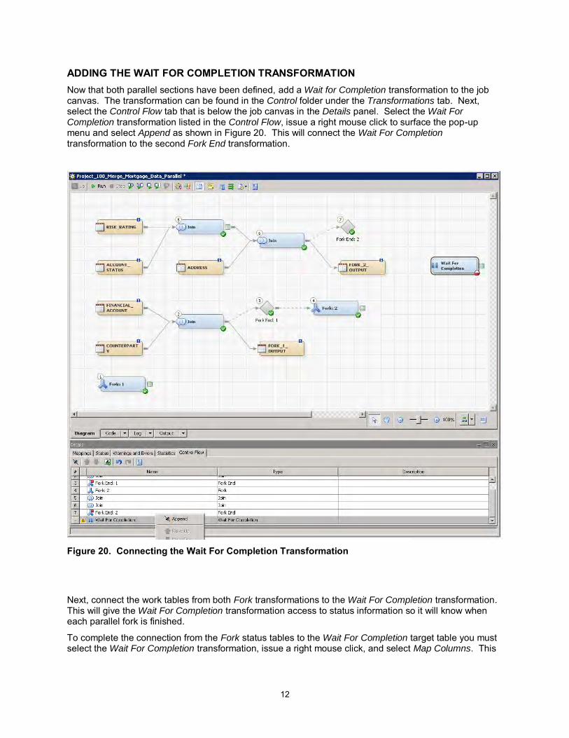
ADDING THE WAIT FOR COMPLETION TRANSFORMATION Now that both parallel sections have been defined, add a Wait for Completion transformation to the job canvas. The transformation can be found in the Control folder under the Transformations tab. Next, select the Control Flow tab that is below the job canvas in the Details panel. Select the Wait For Completion transformation listed in the Control Flow, issue a right mouse click to surface the pop-up menu and select Append as shown in Figure 20. This will connect the Wait For Completion transformation to the second Fork End transformation.
Figure 20. Connecting the Wait For Completion Transformation
Next, connect the work tables from both Fork transformations to the Wait For Completion transformation. This will give the Wait For Completion transformation access to status information so it will know when each parallel fork is finished.
To complete the connection from the Fork status tables to the Wait For Completion target table you must select the Wait For Completion transformation, issue a right mouse click, and select Map Columns. This

13
task is illustrated in Figure 21. If this step is not performed the Wait For Completion transformation may not function as expected.
Figure 21. Wait For Completion – Mapping Columns
COMPLETING THE JOB To complete this example, add a Join transformation and join the two permanent tables produced by each parallel process. Next, add a Table Loader transformation as well as the final target table, Reporting_Data. The final job can be seen in Figure 22.
Figure 22. Final Job with Parallel Sections

14
THE UNDERLYING SAS CODE THAT ALLOWS PARALLEL PROCESSING SAS Data Integration Studio generates code based on the transformations and metadata objects that are placed on the job canvas. When the Fork and Fork End transformations are used, SAS Data Integration Studio generates Multi-Process Connect (MP Connect) code.
With MP Connect, SAS/Connect provides the ability to remote submit an independent code block to a spawned SAS session. If a user has two or more code blocks that have no dependencies, multiple remote submit statements can be executed which will spawn remote SAS sessions that can run in parallel. If the user has a multi-processor machine, the remote sessions can be started on idle CPUs running on the local host. If the site has a Grid, the remote sessions can be started on remote servers.
In the generated code, remote submit blocks are started by the RSUBMIT statement. SAS/Connect also provides a WAITFOR statement that delays downstream processing until the remote code completes.
In addition to benefits such as data lineage and integration with batch scheduling tools, SAS/Data Integration Studio generates this code so the user will not have to build it manually.
THE RUNTIME PROCESS When the job is started, the parallel code sections do not start simultaneously. In this example job, the first Fork transformation executes the RSUBMIT statement which spawns the first parallel section associated with the “F1_” handle. The overhead required when spawning a remote session prevents the job from immediately starting the second parallel process. But once the first spawned session is running, MP Connect technology allows the job to move to the second Fork transformation, executing the RSUBMIT statement that will in turn start the second spawned session associated with the “F2_” handle. Because of the time needed to spawn processes, the first parallel section will start before the second. However, once both spawned sessions are running, they may execute in parallel for a period of time.
The long listing in Figure 23 shows how the job’s permanent target tables are created and updated as the job is executed. To interpret this output, it is helpful to know that on the UNIX operating system SAS datasets are named with the extension “.sas7bdat”. In addition, when those SAS datasets are being updated (i.e., replaced), SAS adds “.lck” to the name to show the table is locked.
Figure 23. Dataset Listing
15
Once the first parallel section is running, table “fork_1_output” is created. As the first parallel section continues to execute, the second parallel section is started and creates SAS dataset “fork_2_output”. At this point both fork sections are running in parallel and both Fork transformation output tables are named with the “.lck” extension to show they are being updated. After the first parallel section completes, the second parallel section continues to run. Once both parallel sections finish, the Wait for Completion transformation allows downstream processing to continue which creates table Reporting_Data.
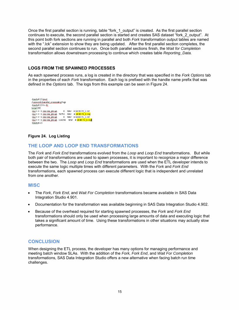
LOGS FROM THE SPAWNED PROCESSES As each spawned process runs, a log is created in the directory that was specified in the Fork Options tab in the properties of each Fork transformation. Each log is prefixed with the handle name prefix that was defined in the Options tab. The logs from this example can be seen in Figure 24.
Figure 24. Log Listing
THE LOOP AND LOOP END TRANSFORMATIONS The Fork and Fork End transformations evolved from the Loop and Loop End transformations. But while both pair of transformations are used to spawn processes, it is important to recognize a major difference between the two. The Loop and Loop End transformations are used when the ETL developer intends to execute the same logic multiple times with different parameters. With the Fork and Fork End transformations, each spawned process can execute different logic that is independent and unrelated from one another.
MISC • The Fork, Fork End, and Wait For Completion transformations became available in SAS Data
Integration Studio 4.901.
• Documentation for the transformation was available beginning in SAS Data Integration Studio 4.902.
• Because of the overhead required for starting spawned processes, the Fork and Fork End transformations should only be used when processing large amounts of data and executing logic that takes a significant amount of time. Using these transformations in other situations may actually slow performance.
CONCLUSION When designing the ETL process, the developer has many options for managing performance and meeting batch window SLAs. With the addition of the Fork, Fork End, and Wait For Completion transformations, SAS Data Integration Studio offers a new alternative when facing batch run time challenges.

16
ACKNOWLEDGMENTS This author would like to thank Tom Hahl and David McCusker from SAS Technical Support for reviewing this paper.
RECOMMENDED READING • Parallel Processing in the SAS Data Integration Studio 4.903: User’s Guide
http://documentation.sas.com/?docsetId=etlug&docsetTarget=n0gxygc7jonw4mn1ucsi9zx049zp.htm&docsetVersion=4.903&locale=en
• MP Connect in the SAS/Connect 9.4 User’s Guide
http://documentation.sas.com/?docsetId=connref&docsetTarget=p1sszj6a6otsy2n1pnseg8vh98l8.htm&docsetVersion=9.4&locale=en
CONTACT INFORMATION Your comments and questions are valued and encouraged. Contact the author at:
Jeff Dyson The Financial Risk Group 919 449 6746 [email protected] frgrisk.com


![Allocation of Parallel Real-Time Tasks in Distributed ... · The fork-join Parallel/Distributed real-time model (P/D tasks) [1], was de-signed to consider such execution pattern](https://img.pdfslide.net/doc/110x75/5facf0b9f6a7a759f92f32c1/allocation-of-parallel-real-time-tasks-in-distributed-the-fork-join-paralleldistributed.jpg)