Embed Size (px)
Citation preview

An Introduction to Robotic Navigation
ECE 450
Introduction to Robotics
Navigational Methods
• Dead-Reckoning
• Landmark-Based Navigation
• Map-Based Navigation
2
A Matter of Scale
• Global – Getting between end-points
• Local– The immediate area about the robot
• Personal– Monitoring the robot and anything in contact
3http://www.doc.ic.ac.uk/~nd/surprise_97/journal/vol4/jmd/
Frame of Reference
• Absolute– Reference is to a fixed stationary point that
whose position is known
• Relative– Reference is to a stationary point whose
absolute position is not known
4
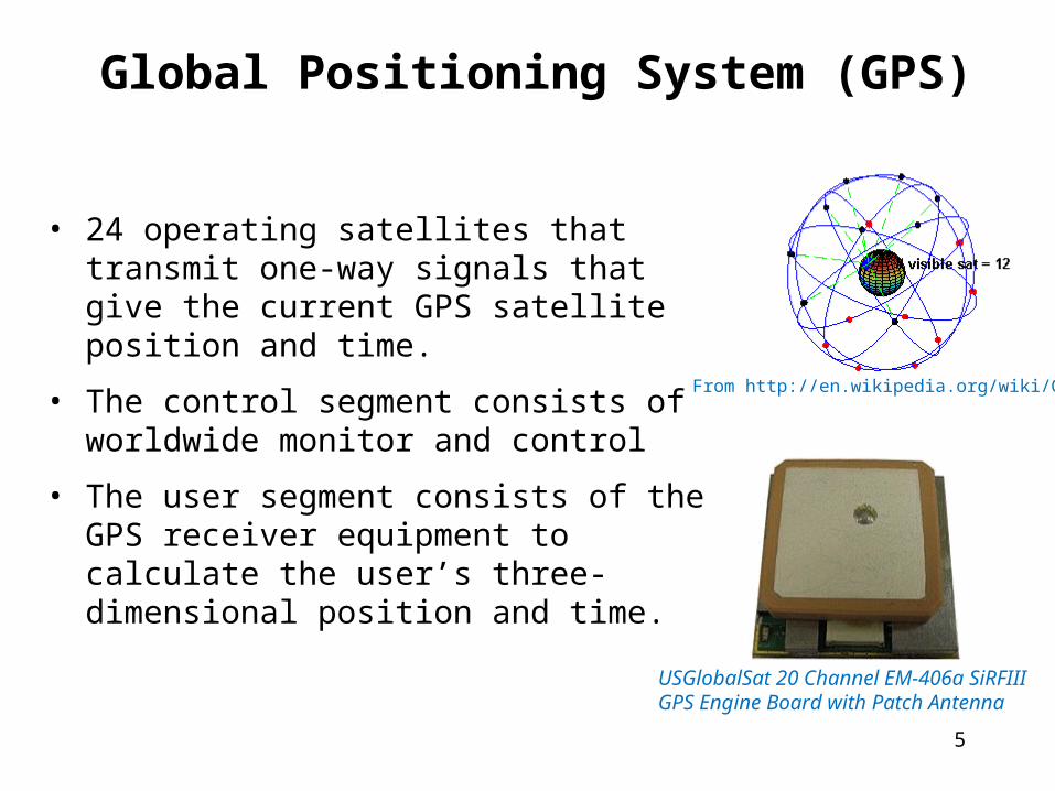
Global Positioning System (GPS)
• 24 operating satellites that transmit one-way signals that give the current GPS satellite position and time.
• The control segment consists of worldwide monitor and control
• The user segment consists of the GPS receiver equipment to calculate the user’s three-dimensional position and time.
5
USGlobalSat 20 Channel EM-406a SiRFIII GPS Engine Board with Patch Antenna
From http://en.wikipedia.org/wiki/GPS
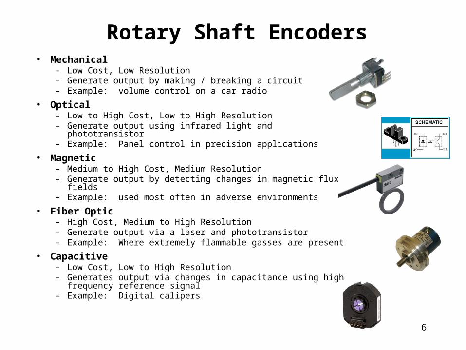
Rotary Shaft Encoders• Mechanical
– Low Cost, Low Resolution– Generate output by making / breaking a circuit– Example: volume control on a car radio
• Optical– Low to High Cost, Low to High Resolution– Generate output using infrared light and phototransistor– Example: Panel control in precision applications
• Magnetic– Medium to High Cost, Medium Resolution– Generate output by detecting changes in magnetic flux fields– Example: used most often in adverse environments
• Fiber Optic– High Cost, Medium to High Resolution– Generate output via a laser and phototransistor– Example: Where extremely flammable gasses are present
• Capacitive– Low Cost, Low to High Resolution– Generates output via changes in capacitance using high frequency
reference signal– Example: Digital calipers
6
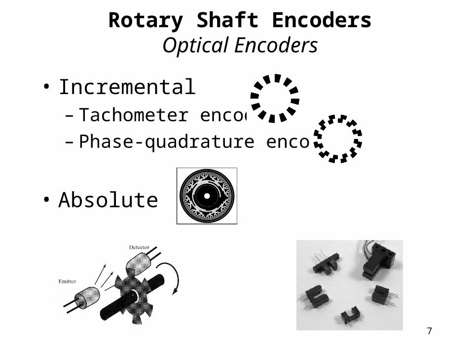
Rotary Shaft EncodersOptical Encoders
• Incremental– Tachometer encoder– Phase-quadrature encoder
• Absolute
7
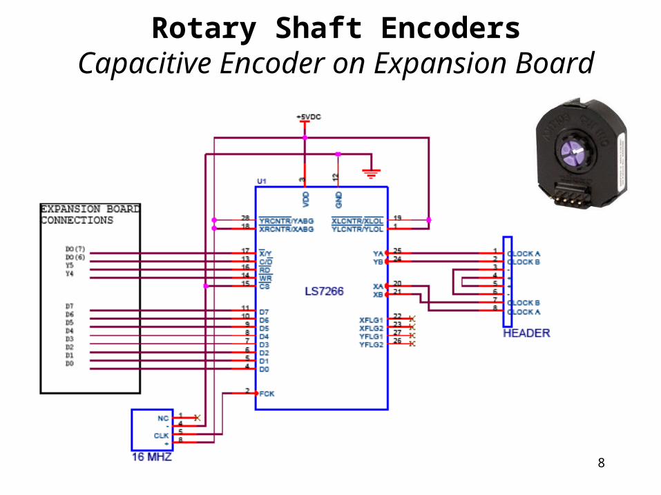
Rotary Shaft EncodersCapacitive Encoder on Expansion Board
8
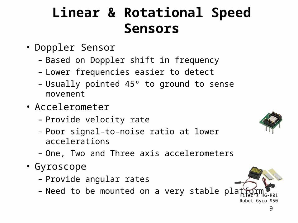
Linear & Rotational Speed Sensors
• Doppler Sensor– Based on Doppler shift in frequency– Lower frequencies easier to detect– Usually pointed 45º to ground to sense movement
• Accelerometer– Provide velocity rate– Poor signal-to-noise ratio at lower accelerations– One, Two and Three axis accelerometers
• Gyroscope– Provide angular rates– Need to be mounted on a very stable platform
9
HiTec's HG-R01 Robot Gyro $50
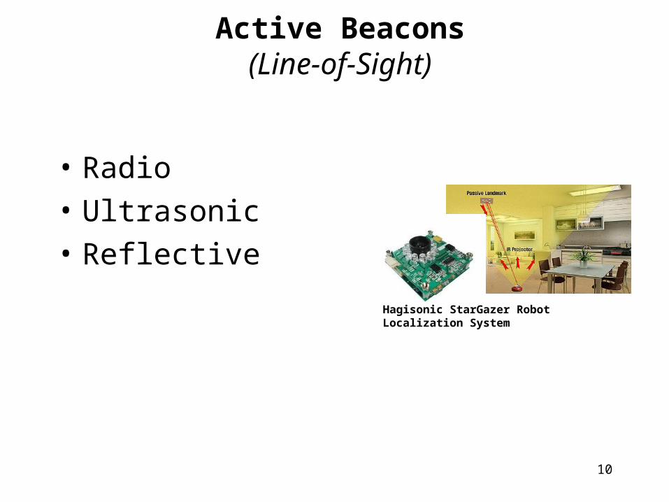
Active Beacons(Line-of-Sight)
• Radio
• Ultrasonic
• Reflective
10
Hagisonic StarGazer Robot Localization System
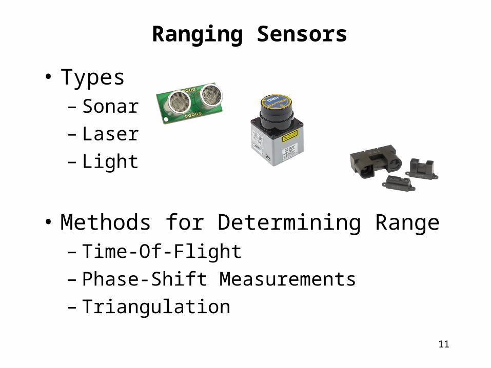
Ranging Sensors
• Types– Sonar– Laser– Light
• Methods for Determining Range– Time-Of-Flight– Phase-Shift Measurements– Triangulation
11
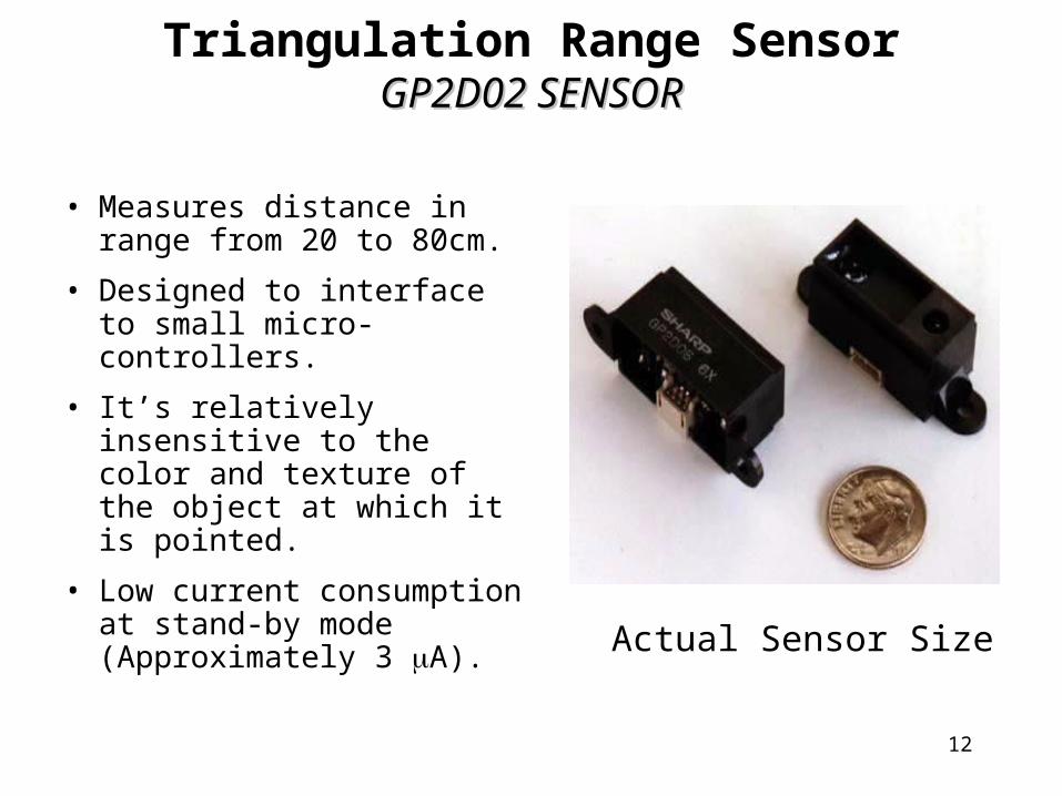
• Measures distance in range from 20 to 80cm.
• Designed to interface to small micro-controllers.
• It’s relatively insensitive to the color and texture of the object at which it is pointed.
• Low current consumption at stand-by mode (Approximately 3 A).
Actual Sensor Size
Triangulation Range SensorGP2D02 SENSORGP2D02 SENSOR
12
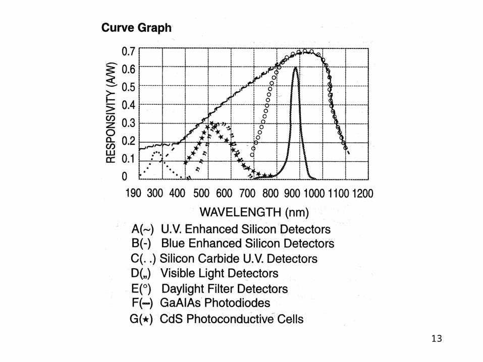
13
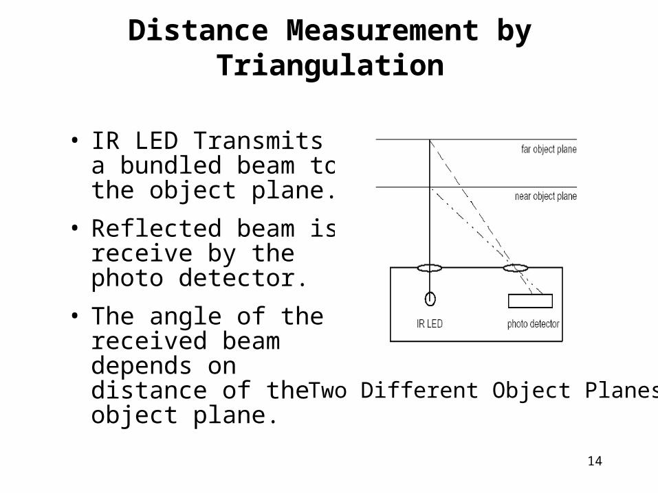
• IR LED Transmits a bundled beam to the object plane.
• Reflected beam is receive by the photo detector.
• The angle of the received beam depends on distance of the object plane.
Two Different Object Planes
Distance Measurement by Triangulation
14
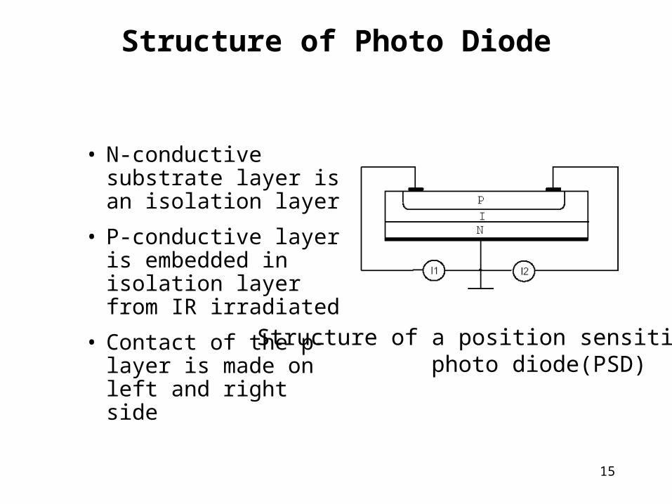
• N-conductive substrate layer is an isolation layer
• P-conductive layer is embedded in isolation layer from IR irradiated
• Contact of the p-layer is made on left and right side
Structure of a position sensitive photo diode(PSD)
Structure of Photo Diode
15
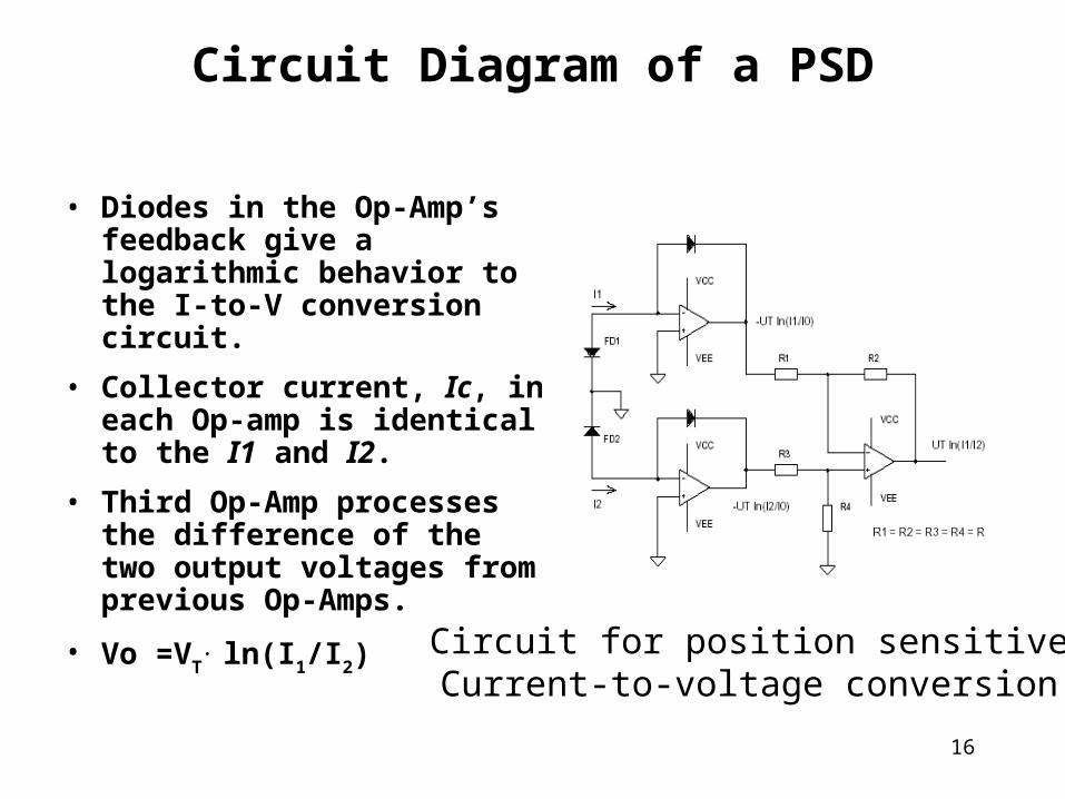
• Diodes in the Op-Amp’s feedback give a logarithmic behavior to the I-to-V conversion circuit.
• Collector current, Ic, in each Op-amp is identical to the I1 and I2.
• Third Op-Amp processes the difference of the two output voltages from previous Op-Amps.
• Vo =VT. ln(I1/I2)
Circuit for position sensitiveCurrent-to-voltage conversion
Circuit Diagram of a PSD
16
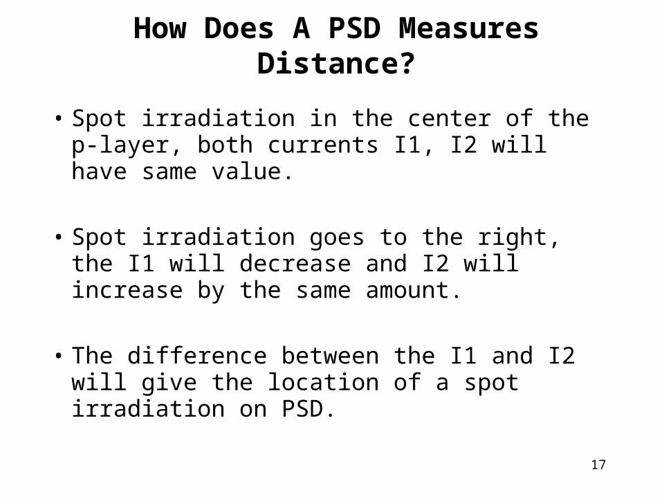
• Spot irradiation in the center of the p-layer, both currents I1, I2 will have same value.
• Spot irradiation goes to the right, the I1 will decrease and I2 will increase by the same amount.
• The difference between the I1 and I2 will give the location of a spot irradiation on PSD.
How Does A PSD Measures Distance?
17
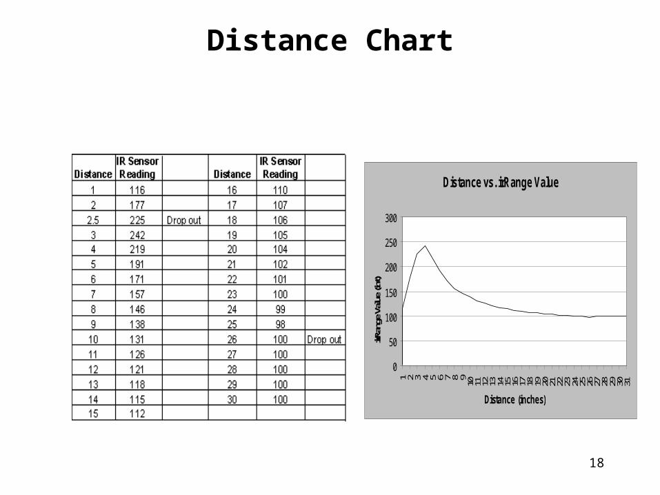
Distance vs. irRange Value
0
50
100
150
200
250
300
1 2 3 4 5 6 7 8 9 10 11 12 13 14 15 16 17 18 19 20 21 22 23 24 25 26 27 28 29 30 31
Distance (inches)
irRan
ge V
alue (
int)
Distance Chart
18
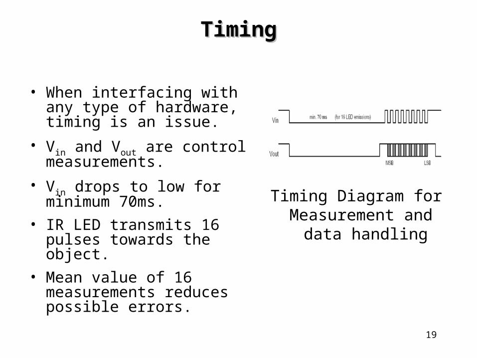
• When interfacing with any type of hardware, timing is an issue.
• Vin and Vout are control measurements.
• Vin drops to low for minimum 70ms.
• IR LED transmits 16 pulses towards the object.
• Mean value of 16 measurements reduces possible errors.
Timing Diagram for Measurement and
data handling
TimingTiming
19
NavigationDead Reckoning
• Two typical methodologies– Odometers
• Advantages:– Good short-term accuracy
– Inexpensive
– High sampling rates
• Disadvantages– Systemic Errors
» Unequal Wheel Diameters
» Misalignment of wheels
» Finite encoder resolution
– Non-systemic Errors
» Uneven floors
» Bumps
» Wheel slippage
– Inertial Navigation• Requires gyroscopically stabilized sensor platform
• Uses 3-axis accelerometer and integrates for velocity & position
• INS on aircraft cost from about $5,000 to $200,000.20
NavigationLandmark-Based
• Natural Landmarks– Typically uses a vision system
– Matches observed features to known landmarks
• Artificial Landmarks– Vision system can more easily detect
• Known pattern
• High contrast with background
• Line Navigation– Can use many types of sensors
• Electromagnetism, reflections, optical sensing…
– Used for many years in buildings, restricts movement
21
NavigationMap Based
• Map Building– Feature extraction from raw data– Fusion of data from various sensors– Auto generation of an abstract model of the environment
• Map Matching– Most challenging due to different angles of observation– Feature extraction– Determining correspondence to model features
• Advantages– Uses existing structures to derive position– Can generate an updated map for other uses– Allows robot to learn about new environment
• Disadvantages– Must have enough stationary & distinguishable features– Sensor map must be accurate– Significant amount of sensing and processing
22