Embed Size (px)
Citation preview
1 | Fuel Cell Technologies Office eere.energy.gov
An Introduction to SAE Hydrogen Fueling Standardization
Will James U.S. Department of Energy Fuel Cell Technologies Office
2 | Fuel Cell Technologies Office eere.energy.gov 2
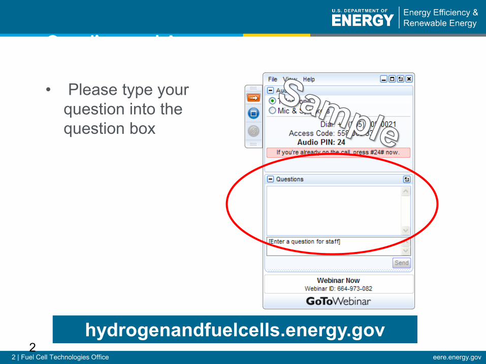
Question and Answer
• Please type your question into the question box
hydrogenandfuelcells.energy.gov
SAE INTERNATIONAL
U.S. DOE WEBINAR:
An Introduction to SAE Hydrogen Fueling Standardization
SAE INTERNATIONAL
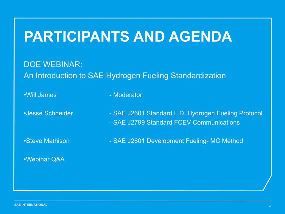
PARTICIPANTS AND AGENDA
4
DOE WEBINAR: An Introduction to SAE Hydrogen Fueling Standardization •Will James - Moderator •Jesse Schneider - SAE J2601 Standard L.D. Hydrogen Fueling Protocol - SAE J2799 Standard FCEV Communications •Steve Mathison - SAE J2601 Development Fueling- MC Method
•Webinar Q&A
SAE INTERNATIONAL DOE Webinar: Introduction to SAE H2 Fueling Standardization 5
SAE HYDROGEN FUELING STANDARDIZATION Jesse Schneider (BMW) SAE J2601 & J2799 Sponsor
SAE INTERNATIONAL
•Hydrogen Fueling Background
•SAE H2 Fueling Standardization
•SAE J2799 Standard
•SAE J2601 Standard
•Lab Testing and Field Verification of Hydrogen Fueling
•Implementing of SAE J2601
DOE Webinar: Introduction to SAE H2 Fueling Standardization 6
Outline
SAE INTERNATIONAL
•Hydrogen Fueling Background
•SAE H2 Fueling Standardization
•SAE J2799 Standard
•SAE J2601 Standard
•Lab Testing and Field Verification of Hydrogen Fueling
•Implementing of SAE J2601
7
Outline
DOE Webinar: Introduction to SAE H2 Fueling Standardization
SAE INTERNATIONAL
Worldwide hydrogen Infrastructure Developments Status 2014
8
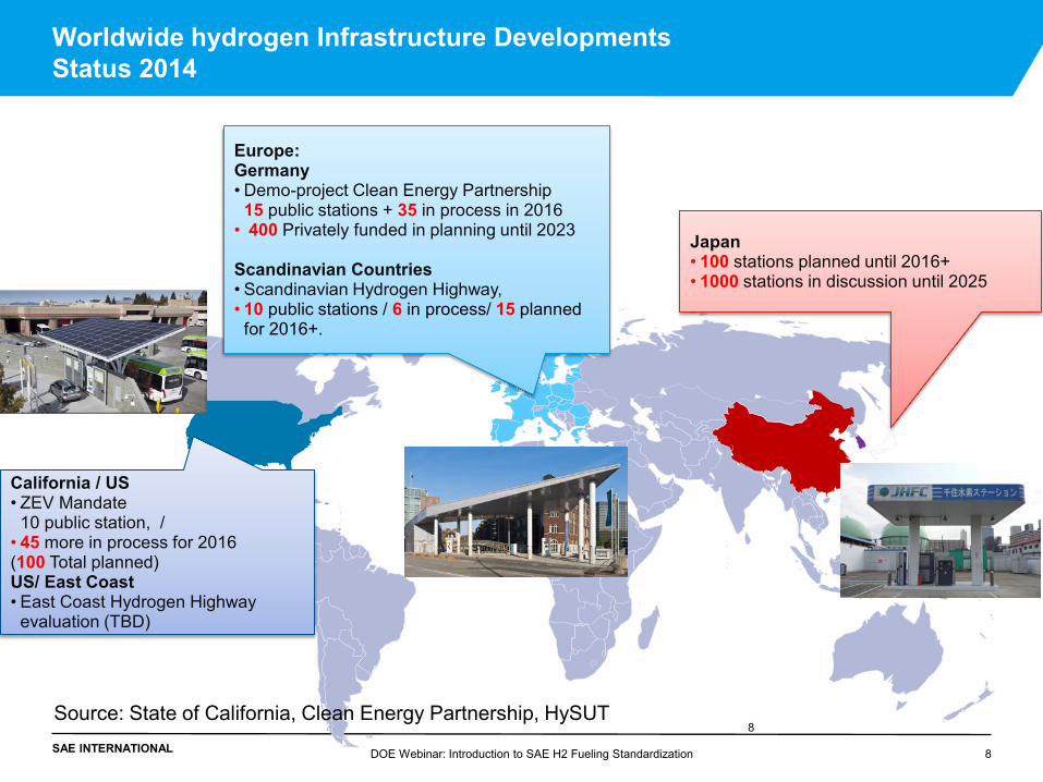
Europe: Germany • Demo-project Clean Energy Partnership
15 public stations + 35 in process in 2016 • 400 Privately funded in planning until 2023
Scandinavian Countries • Scandinavian Hydrogen Highway, • 10 public stations / 6 in process/ 15 planned
for 2016+.
Japan • 100 stations planned until 2016+ • 1000 stations in discussion until 2025
California / US • ZEV Mandate
10 public station, / • 45 more in process for 2016 (100 Total planned) US/ East Coast • East Coast Hydrogen Highway
evaluation (TBD)
8 DOE Webinar: Introduction to SAE H2 Fueling Standardization
Source: State of California, Clean Energy Partnership, HySUT
SAE INTERNATIONAL
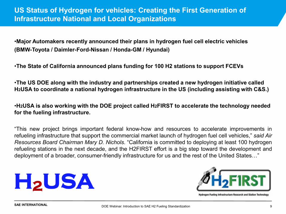
•Major Automakers recently announced their plans in hydrogen fuel cell electric vehicles (BMW-Toyota / Daimler-Ford-Nissan / Honda-GM / Hyundai)
•The State of California announced plans funding for 100 H2 stations to support FCEVs
•The US DOE along with the industry and partnerships created a new hydrogen initiative called H2USA to coordinate a national hydrogen infrastructure in the US (including assisting with C&S.)
•H2USA is also working with the DOE project called H2FIRST to accelerate the technology needed for the fueling infrastructure.
“This new project brings important federal know-how and resources to accelerate improvements in refueling infrastructure that support the commercial market launch of hydrogen fuel cell vehicles,” said Air Resources Board Chairman Mary D. Nichols. “California is committed to deploying at least 100 hydrogen refueling stations in the next decade, and the H2FIRST effort is a big step toward the development and deployment of a broader, consumer-friendly infrastructure for us and the rest of the United States…”
DOE Webinar: Introduction to SAE H2 Fueling Standardization 9
US Status of Hydrogen for vehicles: Creating the First Generation of Infrastructure National and Local Organizations
SAE INTERNATIONAL
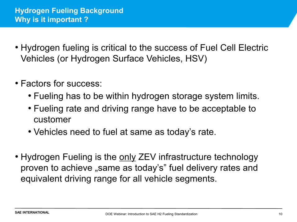
• Hydrogen fueling is critical to the success of Fuel Cell Electric Vehicles (or Hydrogen Surface Vehicles, HSV)
• Factors for success:
• Fueling has to be within hydrogen storage system limits. • Fueling rate and driving range have to be acceptable to
customer • Vehicles need to fuel at same as today’s rate.
• Hydrogen Fueling is the only ZEV infrastructure technology
proven to achieve „same as today’s” fuel delivery rates and equivalent driving range for all vehicle segments.
Hydrogen Fueling Background Why is it important ?
10 DOE Webinar: Introduction to SAE H2 Fueling Standardization
SAE INTERNATIONAL
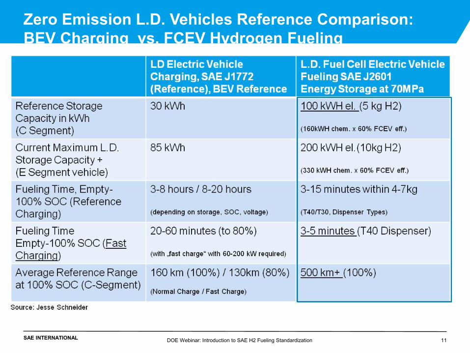
Zero Emission L.D. Vehicles Reference Comparison: BEV Charging vs. FCEV Hydrogen Fueling
11 DOE Webinar: Introduction to SAE H2 Fueling Standardization
SAE INTERNATIONAL
•Hydrogen Fueling Background
•SAE H2 Fueling Standardization
•SAE J2799 Standard
•SAE J2601 Standard
•Lab Testing and Field Verification of Hydrogen Fueling
•Implementing of SAE J2601
DOE Webinar: Introduction to SAE H2 Fueling Standardization 12
Outline
SAE INTERNATIONAL
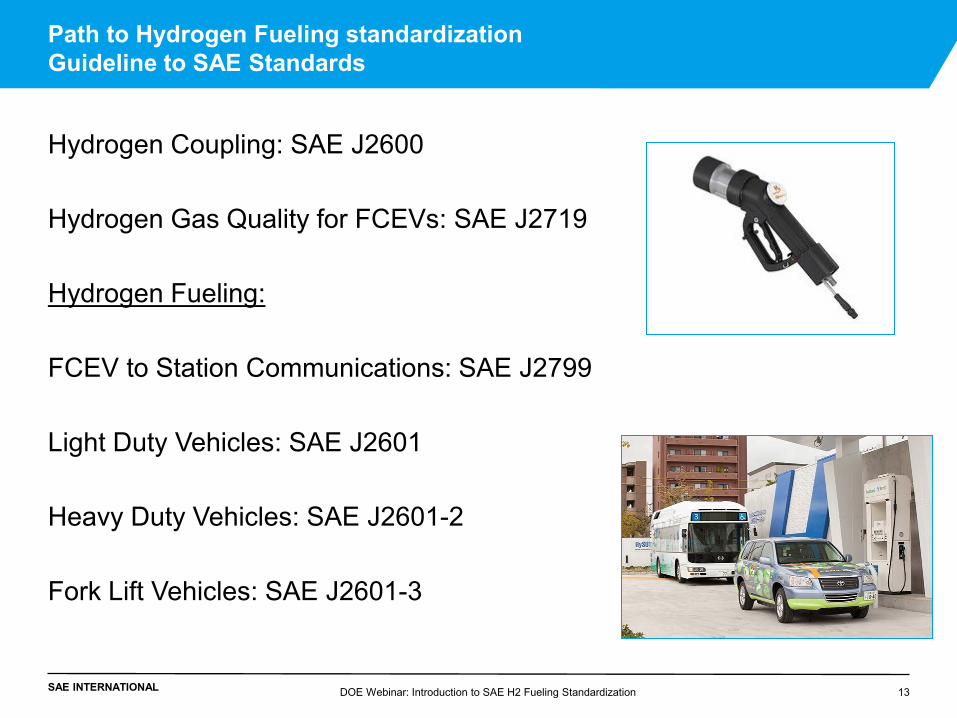
Path to Hydrogen Fueling standardization Guideline to SAE Standards
Hydrogen Coupling: SAE J2600 Hydrogen Gas Quality for FCEVs: SAE J2719 Hydrogen Fueling: FCEV to Station Communications: SAE J2799 Light Duty Vehicles: SAE J2601 Heavy Duty Vehicles: SAE J2601-2 Fork Lift Vehicles: SAE J2601-3
DOE Webinar: Introduction to SAE H2 Fueling Standardization 13
SAE INTERNATIONAL
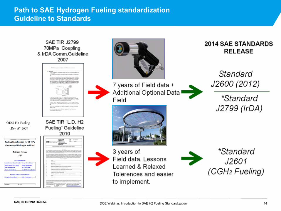
Path to SAE Hydrogen Fueling standardization Guideline to Standards
DOE Webinar: Introduction to SAE H2 Fueling Standardization 14
OEM H2 Fueling
„Rev A“ 2007
SAE INTERNATIONAL
•Hydrogen Fueling Background
•SAE H2 Fueling Standardization
•SAE J2799 Standard
•SAE J2601 Standard
•Lab Testing and Field Verification of Hydrogen Fueling
•Implementing of SAE J2601
DOE Webinar: Introduction to SAE H2 Fueling Standardization 15
Outline
SAE INTERNATIONAL
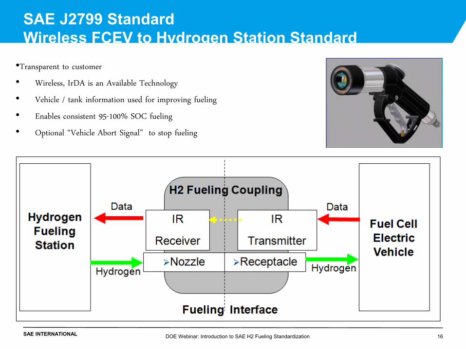
•Transparent to customer
• Wireless, IrDA is an Available Technology
• Vehicle / tank information used for improving fueling
• Enables consistent 95-100% SOC fueling
• Optional “Vehicle Abort Signal” to stop fueling
SAE J2799 Standard Wireless FCEV to Hydrogen Station Standard
DOE Webinar: Introduction to SAE H2 Fueling Standardization 16
SAE INTERNATIONAL DOE Webinar: Introduction to SAE H2 Fueling Standardization 17
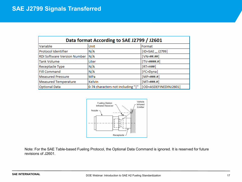
SAE J2799 Signals Transferred
Note: For the SAE Table-based Fueling Protocol, the Optional Data Command is ignored. It is reserved for future revisions of J2601.
SAE INTERNATIONAL
•Hydrogen Fueling Background
•SAE H2 Fueling Standardization
•SAE J2799 Standard
•SAE J2601 Standard
•Lab Testing and Field Verification of Hydrogen Fueling
•Implementing of SAE J2601
DOE Webinar: Introduction to SAE H2 Fueling Standardization 18
Outline
SAE INTERNATIONAL
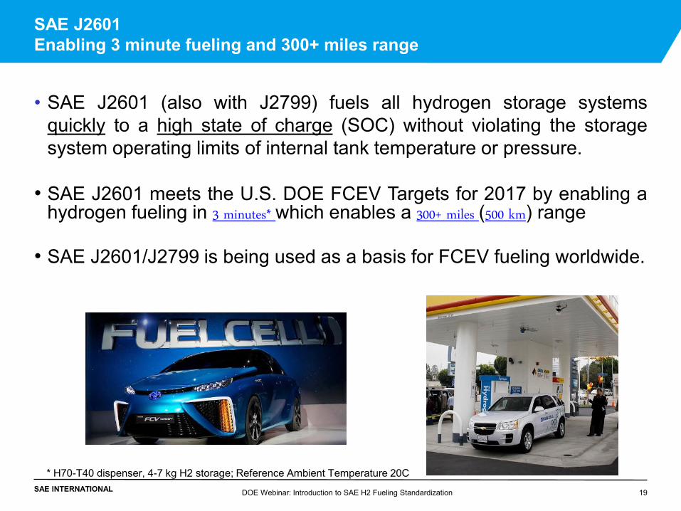
• SAE J2601 (also with J2799) fuels all hydrogen storage systems quickly to a high state of charge (SOC) without violating the storage system operating limits of internal tank temperature or pressure.
• SAE J2601 meets the U.S. DOE FCEV Targets for 2017 by enabling a hydrogen fueling in 3 minutes* which enables a 300+ miles (500 km) range
• SAE J2601/J2799 is being used as a basis for FCEV fueling worldwide.
SAE J2601 Enabling 3 minute fueling and 300+ miles range
* H70-T40 dispenser, 4-7 kg H2 storage; Reference Ambient Temperature 20C
DOE Webinar: Introduction to SAE H2 Fueling Standardization 19
SAE INTERNATIONAL
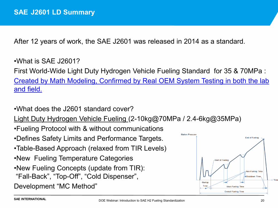
After 12 years of work, the SAE J2601 was released in 2014 as a standard.
•What is SAE J2601? First World-Wide Light Duty Hydrogen Vehicle Fueling Standard for 35 & 70MPa : Created by Math Modeling, Confirmed by Real OEM System Testing in both the lab and field. •What does the J2601 standard cover? Light Duty Hydrogen Vehicle Fueling (2-10kg@70MPa / 2.4-6kg@35MPa) •Fueling Protocol with & without communications •Defines Safety Limits and Performance Targets. •Table-Based Approach (relaxed from TIR Levels) •New Fueling Temperature Categories •New Fueling Concepts (update from TIR): “Fall-Back”, “Top-Off”, “Cold Dispenser”, Development “MC Method”
SAE J2601 LD Summary
DOE Webinar: Introduction to SAE H2 Fueling Standardization 20
SAE INTERNATIONAL
SAE J2601 Steps to Standardization
• FCEV Hydrogen Fueling Simulation Model was created to develop J2601 Look-up Table with industry input • Modeling of Real Tank Properties (from OEMs) • Modeling of Real Station Components (from H2 Suppliers) • Correlation of Models between OEMs
• Lab Validation with Extreme Temperatures and FCEV Tank Volume
Sizes. Testing with • OEM Tanks • H2 Supplier Station Hardware
• J2601 Protocol Field Validation at H2 Stations in Field with real
FCEVs • Field Testing of Stations at Public Locations in three continents • Numerous OEMs FCEV participated
DOE Webinar: Introduction to SAE H2 Fueling Standardization 21
SAE INTERNATIONAL
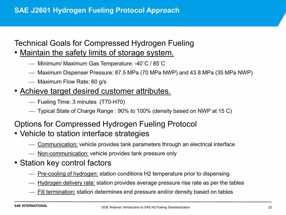
Technical Goals for Compressed Hydrogen Fueling • Maintain the safety limits of storage system.
Minimum/ Maximum Gas Temperature: -40˚C / 85˚C Maximum Dispenser Pressure: 87.5 MPa (70 MPa NWP) and 43.8 MPa (35 MPa NWP) Maximum Flow Rate: 60 g/s
• Achieve target desired customer attributes. Fueling Time: 3 minutes (T70-H70) Typical State of Charge Range : 90% to 100% (density based on NWP at 15 C)
Options for Compressed Hydrogen Fueling Protocol • Vehicle to station interface strategies
Communication: vehicle provides tank parameters through an electrical interface Non-communication: vehicle provides tank pressure only
• Station key control factors Pre-cooling of hydrogen: station conditions H2 temperature prior to dispensing Hydrogen delivery rate: station provides average pressure rise rate as per the tables Fill termination: station determines end pressure and/or density based on tables
DOE Webinar: Introduction to SAE H2 Fueling Standardization 22
SAE J2601 Hydrogen Fueling Protocol Approach
SAE INTERNATIONAL DOE Webinar: Introduction to SAE H2 Fueling Standardization 23
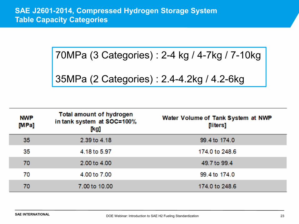
SAE J2601-2014, Compressed Hydrogen Storage System Table Capacity Categories
70MPa (3 Categories) : 2-4 kg / 4-7kg / 7-10kg 35MPa (2 Categories) : 2.4-4.2kg / 4.2-6kg
SAE INTERNATIONAL DOE Webinar: Introduction to SAE H2 Fueling Standardization 24
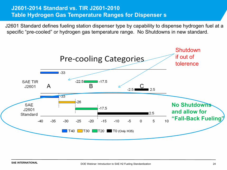
J2601-2014 Standard vs. TIR J2601-2010 Table Hydrogen Gas Temperature Ranges for Dispenser s
J2601 Standard defines fueling station dispenser type by capability to dispense hydrogen fuel at a specific “pre-cooled” or hydrogen gas temperature range. No Shutdowns in new standard.
A B C
Shutdown if out of tolerence
No Shutdowns and allow for “Fall-Back Fueling”
SAE INTERNATIONAL
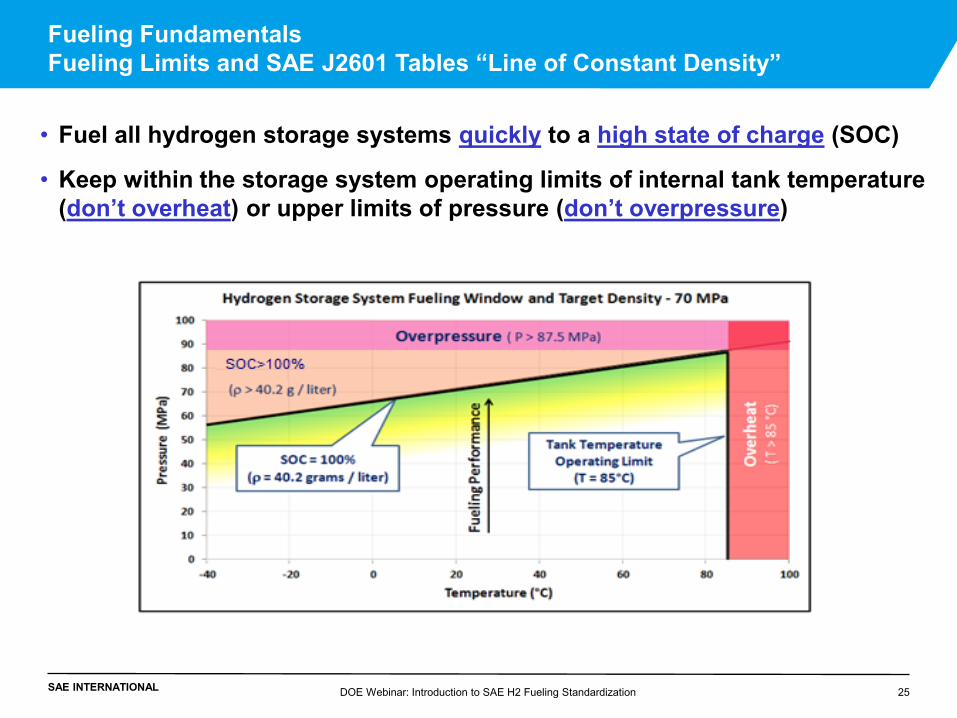
Fueling Fundamentals Fueling Limits and SAE J2601 Tables “Line of Constant Density” • Fuel all hydrogen storage systems quickly to a high state of charge (SOC)
• Keep within the storage system operating limits of internal tank temperature (don’t overheat) or upper limits of pressure (don’t overpressure)
DOE Webinar: Introduction to SAE H2 Fueling Standardization 25
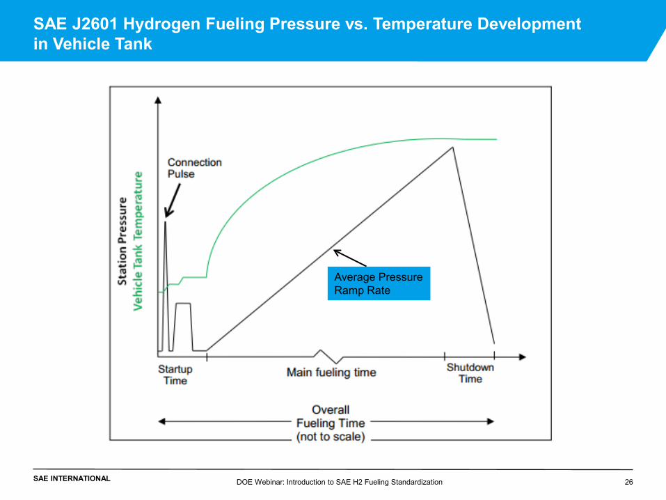
SAE INTERNATIONAL DOE Webinar: Introduction to SAE H2 Fueling Standardization 26
SAE J2601 Hydrogen Fueling Pressure vs. Temperature Development in Vehicle Tank
Average Pressure Ramp Rate
SAE INTERNATIONAL
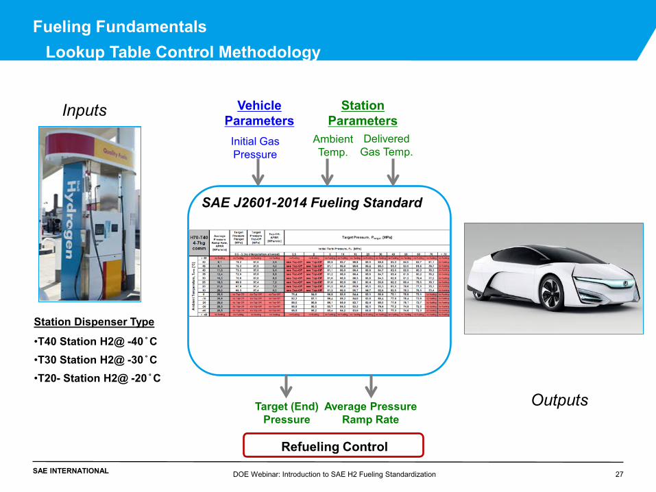
Fueling Fundamentals Lookup Table Control Methodology
Ambient Temp.
Delivered Gas Temp.
Initial Gas Pressure
Vehicle Parameters
Station Parameters
Average Pressure Ramp Rate
Target (End) Pressure
SAE J2601-2014 Fueling Standard
Outputs
Refueling Control
Inputs
Station Dispenser Type
•T40 Station H2@ -40 ̊ C •T30 Station H2@ -30 ̊ C •T20- Station H2@ -20 ̊ C
DOE Webinar: Introduction to SAE H2 Fueling Standardization 27
SAE INTERNATIONAL
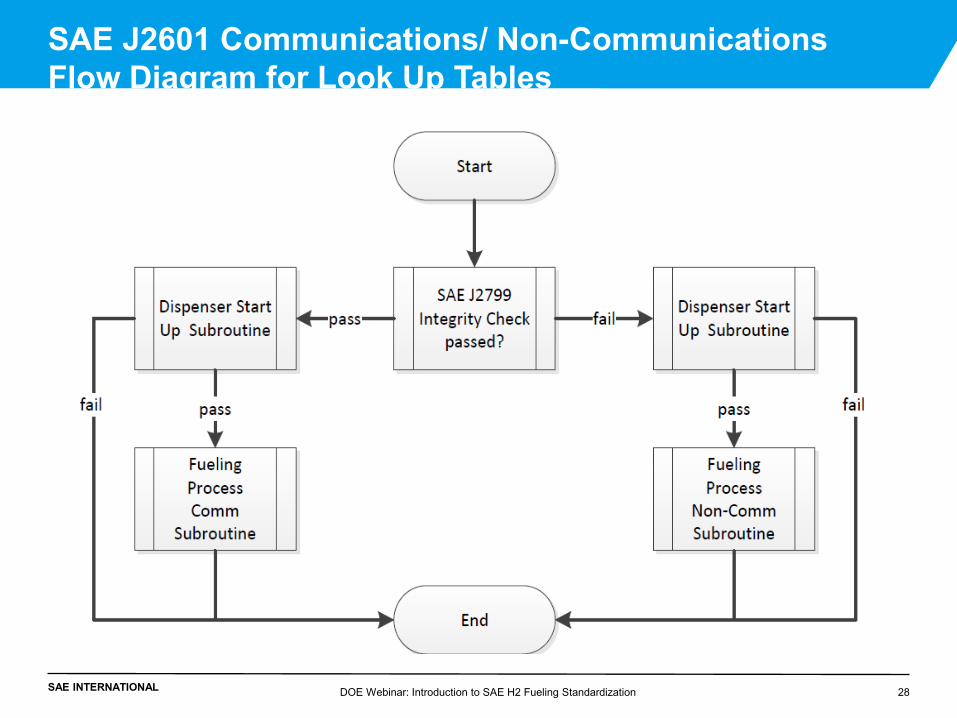
SAE J2601 Communications/ Non-Communications Flow Diagram for Look Up Tables
DOE Webinar: Introduction to SAE H2 Fueling Standardization 28
SAE INTERNATIONAL
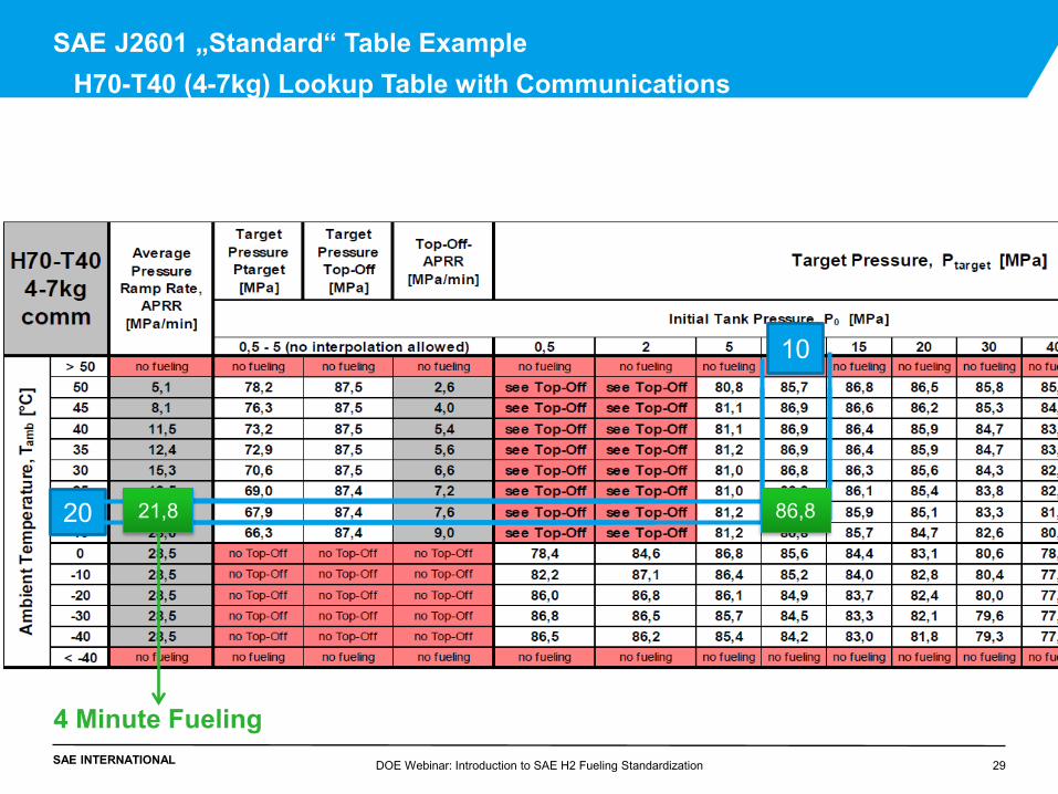
SAE J2601 „Standard“ Table Example H70-T40 (4-7kg) Lookup Table with Communications
DOE Webinar: Introduction to SAE H2 Fueling Standardization 29
10
20 86,8 21,8
4 Minute Fueling
SAE INTERNATIONAL
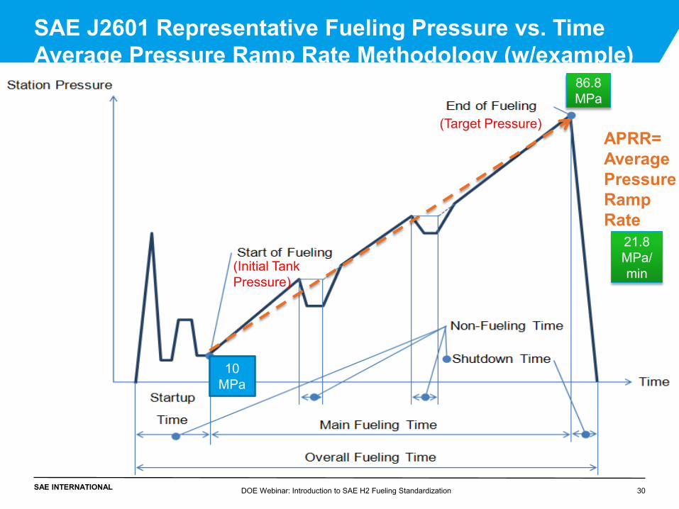
SAE J2601 Representative Fueling Pressure vs. Time Average Pressure Ramp Rate Methodology (w/example)
APRR= Average Pressure Ramp Rate
(Target Pressure)
DOE Webinar: Introduction to SAE H2 Fueling Standardization 30
(Initial Tank Pressure)
21.8 MPa/min
86.8 MPa
10 MPa
SAE INTERNATIONAL
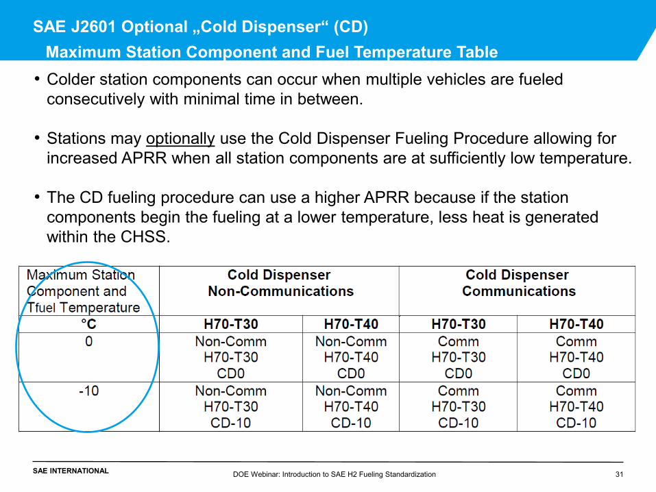
SAE J2601 Optional „Cold Dispenser“ (CD) Maximum Station Component and Fuel Temperature Table
DOE Webinar: Introduction to SAE H2 Fueling Standardization 31
• Colder station components can occur when multiple vehicles are fueled consecutively with minimal time in between.
• Stations may optionally use the Cold Dispenser Fueling Procedure allowing for
increased APRR when all station components are at sufficiently low temperature.
• The CD fueling procedure can use a higher APRR because if the station components begin the fueling at a lower temperature, less heat is generated within the CHSS.
SAE INTERNATIONAL
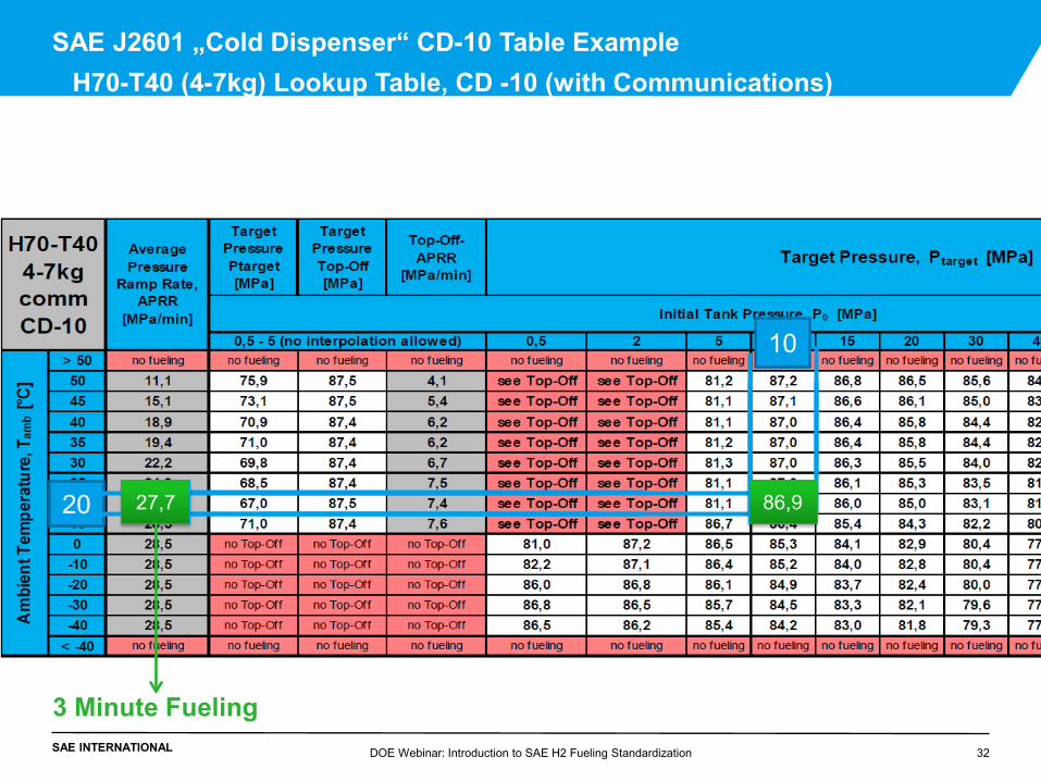
SAE J2601 „Cold Dispenser“ CD-10 Table Example H70-T40 (4-7kg) Lookup Table, CD -10 (with Communications)
DOE Webinar: Introduction to SAE H2 Fueling Standardization 32
10
20 86,9 27,7
3 Minute Fueling
SAE INTERNATIONAL
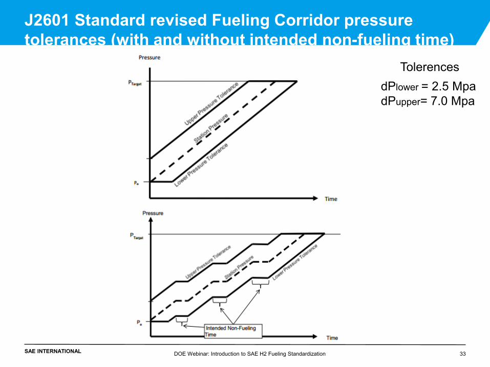
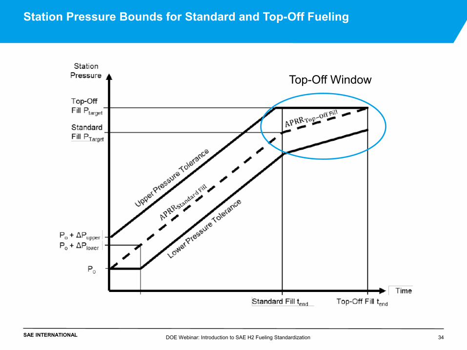
J2601 Standard revised Fueling Corridor pressure tolerances (with and without intended non-fueling time)
dPlower = 2.5 Mpa dPupper= 7.0 Mpa
Tolerences
DOE Webinar: Introduction to SAE H2 Fueling Standardization 33
SAE INTERNATIONAL DOE Webinar: Introduction to SAE H2 Fueling Standardization 34
Station Pressure Bounds for Standard and Top-Off Fueling
Top-Off Window
SAE INTERNATIONAL DOE Webinar: Introduction to SAE H2 Fueling Standardization 35
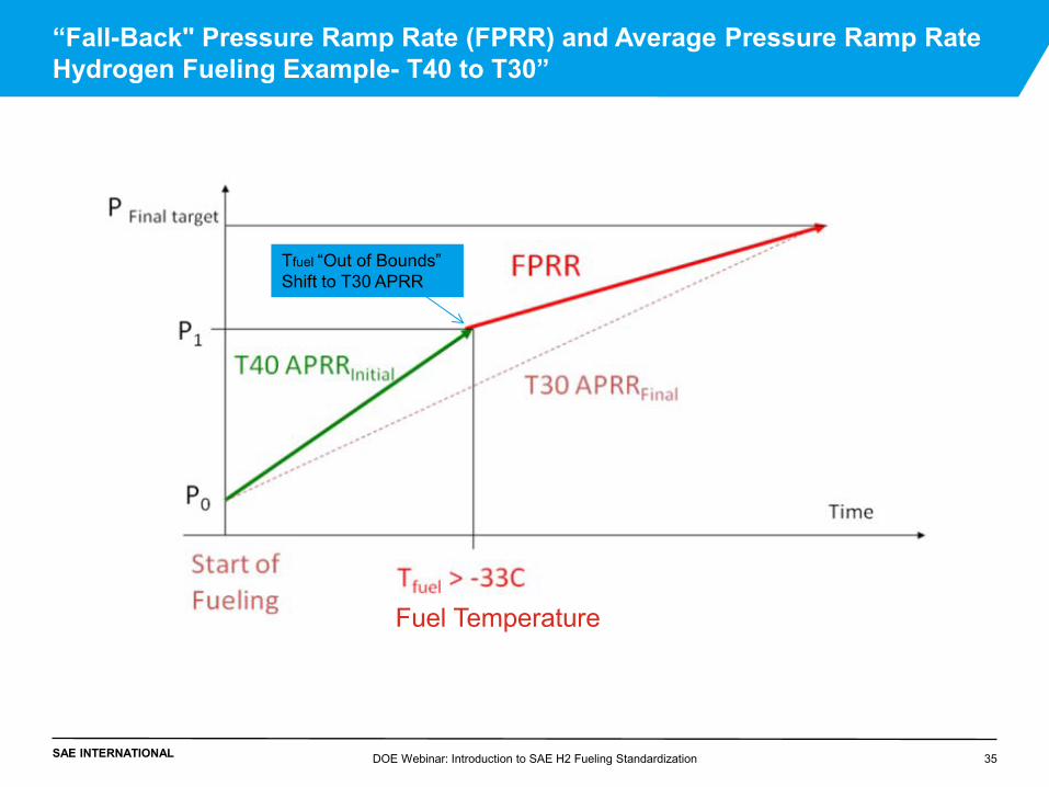
“Fall-Back" Pressure Ramp Rate (FPRR) and Average Pressure Ramp Rate Hydrogen Fueling Example- T40 to T30”
Tfuel “Out of Bounds” Shift to T30 APRR
Fuel Temperature
SAE INTERNATIONAL
•Hydrogen Fueling Background
•SAE H2 Fueling Standardization
•SAE J2799 Standard
•SAE J2601 Standard
•Theory and Modeling/ Tables
•Lab Testing and Field Verification of Hydrogen Fueling
•Implementing of SAE J2601
DOE Webinar: Introduction to SAE H2 Fueling Standardization 36
Outline
SAE INTERNATIONAL
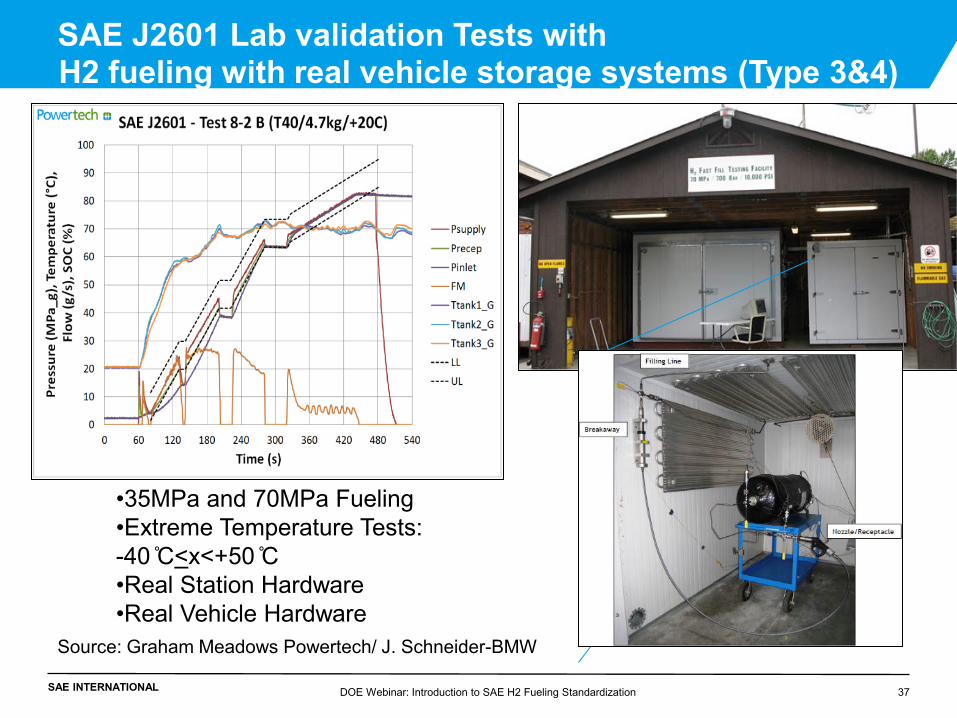
SAE J2601 Lab validation Tests with H2 fueling with real vehicle storage systems (Type 3&4)
•35MPa and 70MPa Fueling •Extreme Temperature Tests: -40 ̊C<x<+50 ̊C •Real Station Hardware •Real Vehicle Hardware
Source: Graham Meadows Powertech/ J. Schneider-BMW
DOE Webinar: Introduction to SAE H2 Fueling Standardization 37
SAE INTERNATIONAL
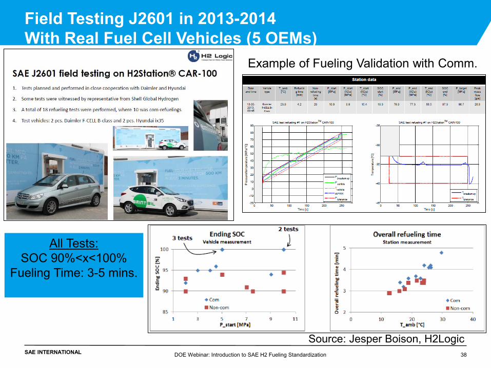
Field Testing J2601 in 2013-2014 With Real Fuel Cell Vehicles (5 OEMs)
All Tests: SOC 90%<x<100%
Fueling Time: 3-5 mins.
Example of Fueling Validation with Comm.
Source: Jesper Boison, H2Logic DOE Webinar: Introduction to SAE H2 Fueling Standardization 38
SAE INTERNATIONAL
•Hydrogen Fueling Background
•SAE H2 Fueling Standardization
•SAE J2799 Standard
•SAE J2601 Standard
•Theory and Modeling/ Tables
•Lab Testing and Field Verification of Hydrogen Fueling
•Implementing of SAE J2601
DOE Webinar: Introduction to SAE H2 Fueling Standardization 39
Outline
SAE INTERNATIONAL DOE Webinar: Introduction to SAE H2 Fueling Standardization 40
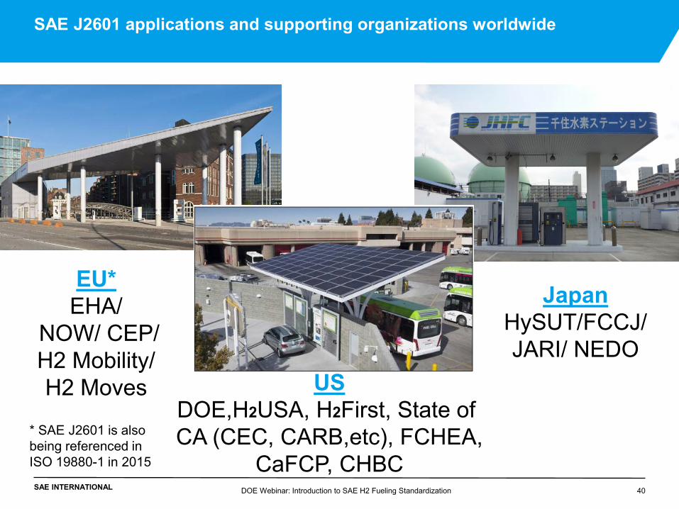
SAE J2601 applications and supporting organizations worldwide
US DOE,H2USA, H2First, State of CA (CEC, CARB,etc), FCHEA,
CaFCP, CHBC
EU* EHA/
NOW/ CEP/ H2 Mobility/ H2 Moves
Japan HySUT/FCCJ/ JARI/ NEDO
* SAE J2601 is also being referenced in ISO 19880-1 in 2015
SAE INTERNATIONAL
Conclusion SAE J2601/J2799 enables standard fueling / verification needed
•The J2601 and J2799 Standards are enablers to fuel cell vehicle commercialization, worldwide, and enable consistent, safe refueling for Fuel Cell Vehicles and are be available on the SAE Website: http://standards.sae.org/j2601_201407/ http://standards.sae.org/j2799_201404/ •J2601 has been validated with real automaker vehicles and tanks and hydrogen stations and documented in the SAE Technical Report (http://papers.sae.org/2014-01-1990/): “Validation and Sensitivity Studies for SAE J2601” available in June 2014.
•At station commissioning, dispensers need to be validated that they meet SAE J2601/ J2799 by a Hydrogen Dispenser Station Test Apparatus (http://papers.sae.org/2005-01-0002/). Note, organizations such H2First for the US, HySut in Japan and CEP in Germany are in process of implementing HSTAs. DOE Webinar: Introduction to SAE H2 Fueling Standardization 41
SAE INTERNATIONAL
SAE J2600 - Compressed Hydrogen Surface Vehicle Fueling Connection Devices http://standards.sae.org/j2600_201211/ SAE J2601/2 - Hydrogen Bus Fueling Technical Information Report http://www.sae.org/technical/standards/J2601/2_201409 SAE J2601/3 - Fueling Protocol for Gaseous Hydrogen Powered Heavy Duty Vehicles http://standards.sae.org/j2601/3_201306/ SAE J2578 - Recommended Practice for General Fuel Cell Vehicle Safety http://standards.sae.org/j2578_201408/ SAE J2579 - Standard for Fuel Systems in Fuel Cell and Other Hydrogen Vehicles http://standards.sae.org/j2579_201303/ SAE J2719 - Hydrogen Fuel Quality for Fuel Cell Vehicles. http://standards.sae.org/j2719_201109/
DOE Webinar: Introduction to SAE H2 Fueling Standardization 42
Conclusion Continued Links to other SAE Documents
SAE INTERNATIONAL DOE Webinar: Introduction to SAE H2 Fueling Standardization 43
SAE J2601 DEVELOPMENT FUELING- MC METHOD (APPENDIX H) Steve Mathison (Honda R&D Americas, Inc.)
SAE INTERNATIONAL DOE Webinar: Introduction to SAE H2 Fueling Standardization 44
SAE J2601 Development Fueling: MC Default Fill - Philosophy
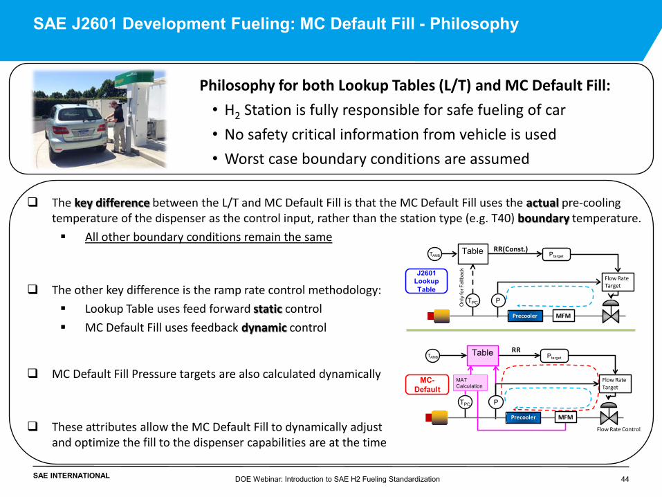
Philosophy for both Lookup Tables (L/T) and MC Default Fill: • H2 Station is fully responsible for safe fueling of car • No safety critical information from vehicle is used • Worst case boundary conditions are assumed
The key difference between the L/T and MC Default Fill is that the MC Default Fill uses the actual pre-cooling temperature of the dispenser as the control input, rather than the station type (e.g. T40) boundary temperature.
All other boundary conditions remain the same
The other key difference is the ramp rate control methodology:
Lookup Table uses feed forward static control
MC Default Fill uses feedback dynamic control
MC Default Fill Pressure targets are also calculated dynamically
These attributes allow the MC Default Fill to dynamically adjust and optimize the fill to the dispenser capabilities are at the time
Table
Onl
y fo
r Fal
lbac
k
Precooler
TPC
MFM
RR(Const.)
P
Flow Rate Target
J2601 Lookup Table
Ptarget
MC-Default
TAMB
Flow Rate Control
TPC
RR
P
Flow Rate Target
PtargetTAMB
Precooler MFM
MAT Calculation
Table
SAE INTERNATIONAL DOE Webinar: Introduction to SAE H2 Fueling Standardization 45
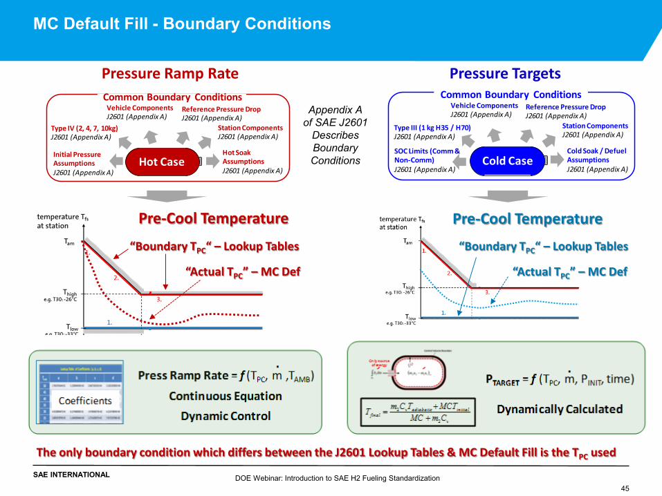
MC Default Fill - Boundary Conditions
Hot Case
Vehicle ComponentsJ2601 (Appendix A)
Station ComponentsJ2601 (Appendix A)
Hot Soak AssumptionsJ2601 (Appendix A)
Initial PressureAssumptionsJ2601 (Appendix A)
Type IV (2, 4, 7, 10kg)J2601 (Appendix A)
Reference Pressure DropJ2601 (Appendix A)
Common Boundary Conditions
Hot Case
Vehicle ComponentsJ2601 (Appendix A)
Station ComponentsJ2601 (Appendix A)
Cold Soak / DefuelAssumptionsJ2601 (Appendix A)
SOC Limits (Comm & Non-Comm)J2601 (Appendix A)
Type III (1 kg H35 / H70)J2601 (Appendix A)
Reference Pressure DropJ2601 (Appendix A)
Cold Case
Common Boundary Conditions
Pre-Cool Temperature
The only boundary condition which differs between the J2601 Lookup Tables & MC Default Fill is the TPC used
“Actual TPC” – MC Def
Pre-Cool Temperature
“Boundary TPC“ – Lookup Tables
Pressure Ramp Rate Pressure Targets
Appendix A of SAE J2601
Describes Boundary Conditions
“Boundary TPC“ – Lookup Tables
“Actual TPC” – MC Def
SAE INTERNATIONAL DOE Webinar: Introduction to SAE H2 Fueling Standardization 46
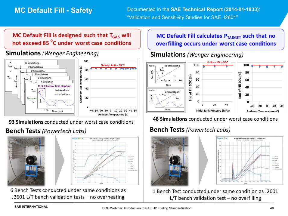
MC Default Fill - Safety
Tamb
TPC
30
Pre-Cool Temp
Time (sec)
Tamb
TPC
30
Pre-Cool Temp
Time (sec)
Tamb
TPC
15
Pre-Cool Temp
Time (sec)30 60
Tamb
TPC
30
Pre-Cool Temp
Time (sec)
TPC-expected
TPC-expected
Tamb
TPC
30
Pre-Cool Temp
Time (sec)
Tamb
TPC
60
Pre-Cool Temp
Time (sec)
TPC-expectedTamb
TPC
60
Pre-Cool Temp
Time (sec)
TPC-expected
MC Fill Control Time Step Size
60 simulations
23 simulations
2 simulations2 simulations
2 simulations
1 simulation
3 simulations
0
20
40
60
80
100
-40 -30 -20 -10 0 10 20 30 40 50
Max
imum
Gas
Tem
pera
ture
(C)
Ambient Temperature (C)
Safety Limit = 85oC
93 Simulations conducted under worst case conditions
6 Bench Tests conducted under same conditions as J2601 L/T bench validation tests – no overheating
48 Simulations conducted under worst case conditions
1 Bench Test conducted under same condition as J2601 L/T bench validation test – no overfilling
0
20
40
60
80
100
0 20 40
End
of F
ill S
OC
(%)
Initial Tank Pressure (MPa)
Tamb
TPC
Pressure
T PC
/ SO
C
100%
Pinit
TPC
Pressure
T PC
/ SO
C
100%
Pinit
45 simulations
3 simulations
0
20
40
60
80
100
-40 -20 0 20 40
End
of F
ill S
OC
(%)
Ambient Temperature (C)
Limit <= 100% SOC
Time
Time
Simulations (Wenger Engineering) Simulations (Wenger Engineering)
Bench Tests (Powertech Labs) Bench Tests (Powertech Labs)
Documented in the SAE Technical Report (2014-01-1833): “Validation and Sensitivity Studies for SAE J2601”
SAE INTERNATIONAL DOE Webinar: Introduction to SAE H2 Fueling Standardization 47
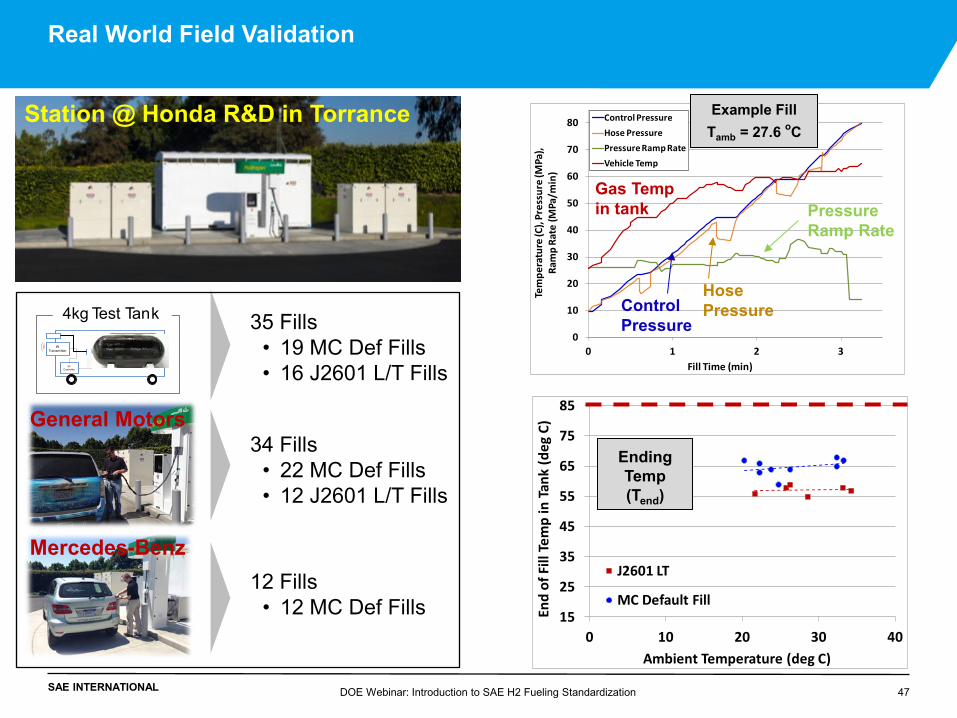
Real World Field Validation
Station @ Honda R&D in Torrance
水素タンク
水素タンクIR
Transmitter
IR Controller
4kg Test Tank 35 Fills • 19 MC Def Fills • 16 J2601 L/T Fills
34 Fills • 22 MC Def Fills • 12 J2601 L/T Fills
General Motors
12 Fills • 12 MC Def Fills 15
25
35
45
55
65
75
85
0 10 20 30 40
End
of F
ill T
emp
in T
ank
(deg
C)
Ambient Temperature (deg C)
J2601 LT
MC Default Fill
Ending Temp (Tend)
Mercedes-Benz
0
10
20
30
40
50
60
70
80
0 1 2 3
Tem
pera
ture
(C),
Pres
sure
(MPa
),
Ram
p Ra
te (M
Pa/m
in)
Fill Time (min)
Control PressureHose PressurePressure Ramp RateVehicle Temp
Example Fill
Tamb = 27.6 oC
Gas Temp in tank
Control Pressure
Hose Pressure
Pressure Ramp Rate
SAE INTERNATIONAL
• The MC Default Fill is currently a non-normative protocol defined in Appendix H of SAE J2601
• The MC Default Fill offers many benefits:
• Customer Experience : – Fast fueling times – More consistency in fueling time (i.e. less variability due to changes in ambient temperature)
• Station Design: – More flexibility due to the MC Fill’s adaptive qualities
• H2 Infrastructure: – Better station utilization (more vehicles per hour can fuel due to quicker fill times)
• In-field use and validation of the MC Default Fill is ongoing:
• Two OEMs have conducted a combined 35 MC Default Fills to date • Other Dispenser Manufacturers are in the process of implementing the MC Default Fill
• The SAE Interface Task Force is evaluating the data from this real world usage and is
considering making the MC Default Fill a normative fueling protocol in a future revision to SAE J2601.
DOE Webinar: Introduction to SAE H2 Fueling Standardization 48
MC Default Fill - Conclusions
SAE INTERNATIONAL
DOE Webinar Q&A
49
•Will James - Contact: [email protected] •Jesse Schneider - Contact: [email protected], [email protected], •Steve Mathison - Contact: [email protected]
DOE WEBINAR: An Introduction to SAE Hydrogen Fueling Standardization
Informational: Face-to-Face Training for SAE Hydrogen Fueling Standards at the Fuel Cell Seminar in Los Angeles California on November 10th, 9-11 AM PT.
SAE INTERNATIONAL
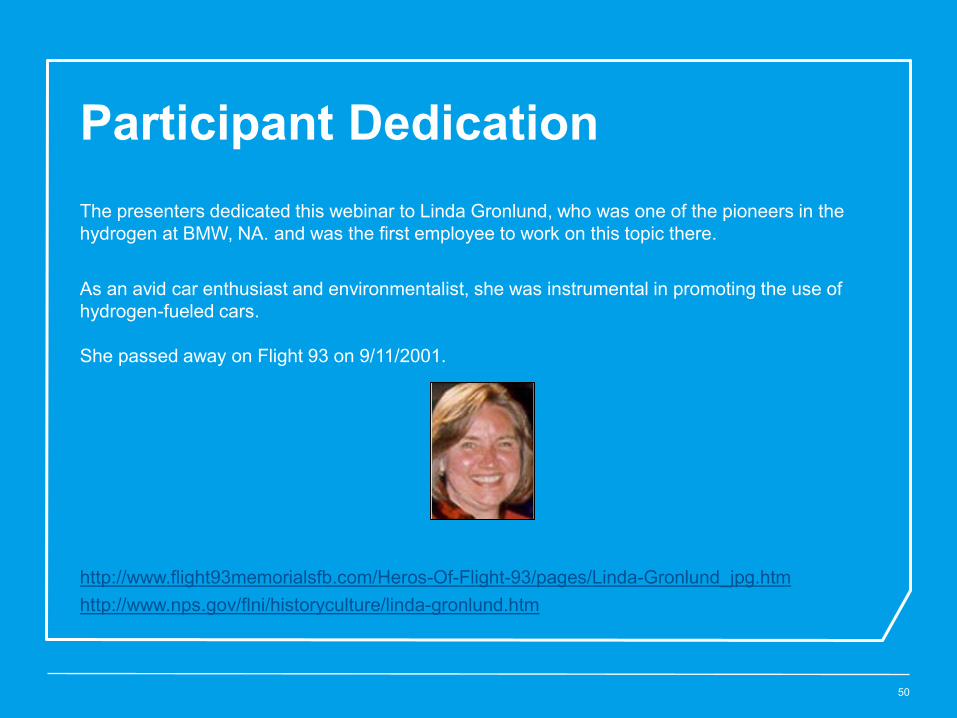
Participant Dedication
50
The presenters dedicated this webinar to Linda Gronlund, who was one of the pioneers in the hydrogen at BMW, NA. and was the first employee to work on this topic there. As an avid car enthusiast and environmentalist, she was instrumental in promoting the use of hydrogen-fueled cars. She passed away on Flight 93 on 9/11/2001. http://www.flight93memorialsfb.com/Heros-Of-Flight-93/pages/Linda-Gronlund_jpg.htm http://www.nps.gov/flni/historyculture/linda-gronlund.htm