Embed Size (px)
Citation preview

An introduction to the Universal Smart Energy Framework
www.smartenergycollective.com Version 1.0

© 2013 Smart Energy Collective, Arnhem, the Netherlands. All rights reserved.
This document contains confidential information that shall not be transmitted to any third party without written consent of Smart Energy Collective. The same applies to file copying (including but not limited to electronic copies), wholly or partially.
It is prohibited to change any and all versions of this document in any manner whatsoever, including but not limited to dividing it into parts. In case of a conflict between an electronic version (e.g. PDF file) and the original paper version provided by the Smart Energy Collective, the latter will prevail.
Smart Energy Collective and/or its associated companies disclaim liability for any direct, indirect, consequential or incidental damages that may result from the use of the information or data, or from the inability to use the information or data contained in this document.
Top-right cover image courtesy of the Image Science & Analysis Laboratory, NASA Johnson Space Center.

3
The Smart Energy Collective (SEC) is an alliance of national and international companies
that agreed to collaborate on the development of a Universal Smart Energy Framework
(USEF). This framework will provide a set of specifications, designs and implementation
guidelines that enable you to establish a fully functional smart energy system. USEF
allows each partner to develop smart energy products and services that together form a
commercially viable smart energy system that allows large-scale international deployment.
USEF will be validated and improved in a number of large-scale demonstration projects to
commoditize these products and services. Currently already five demonstration projects
are under development in the Netherlands connecting thousands of residential and small
business end-users. This document summarizes USEF and introduces you to its content
and components: the interaction model, market-based control mechanism, grid operations,
smart energy services, privacy and security and ICT architecture.

An introduction to the Universal Smart Energy Framework
4
1 The need for a Universal Smart Energy Framework 6
2 The scope of USEF 8
3 Value creation 103.1 (Local) Peak load reduction on the grid 103.2 Active Balancing 103.3 Providing Insight 11
4 Yellow is the new green 12
5 Democratizing the energy market 14
6 Roles and responsibilities 16
7 The USEF interaction model 197.1 Combination of roles in business models 21
8 Market-based Control Mechanism 238.1 Plan 248.2 Validate 258.3 Operate 268.4 Settlement 26
9 Grid operations 289.1 Normal Operations (Green Regime) 289.2 Capacity Management (Yellow Regime) 289.3 Graceful Degradation (Orange Regime) 29
10 Services and propositions 3010.1 General Services 3010.2 Flexibility Services 3110.3 Ancillary Smart Energy Services 3210.4 Propositions 32
11 Unleashing the flexibility 3411.1 Soft Control 3411.2 Delegated Control 3511.3 Different types of demand response 35
12 Quantifying the value creation 3612.1 The value creation model 37
13 Privacy & Security 3813.1 Legal framework 3813.2 Value creation through data sharing 3913.3 Identification, authentication, authorization and trust 4013.4 Data management and communication 4013.5 Recovery 41
Table of Contents
5
14 ICT Architecture 4214.1 Supporting framework 4414.2 Shared infrastructure 44
15 Standardization 4515.1 Relation with other smart grid standardization initiatives 4515.2 The smart grid ecosystem of standards 4615.3 Building the ecosystem 4615.4 Tried and trusted 46
16 Improve, Rinse and Repeat 47
Acknowledgements 49

An introduction to the Universal Smart Energy Framework
6
There is a global drive to drastically reduce CO2 emissions
due to global warming and a need to reduce our dependence
on (imported) fossil fuels. Growing environmental and energy
awareness results in energy savings and an increased use
of renewable energy. A significant share of it will be derived
from intermittent, local energy sources such as wind and
sun. Coupled with an increasing demand for electricity,
largely driven by the large-scale introduction of electric
transport, space heating by heat pumps and a growing
number of local energy communities, a need emerges for a
‘new order’ in the supply of energy that optimally matches
the changing social context of the 21st century.
Currently Europe’s power exchange markets form a fully integrated chain that allows free exchange of energy within the capacity limits of the interconnecting transmission lines as depicted in the figure above. Large industries form an integral part of the system and do have free access to the energy market. Trading services have already been introduced into the market to provide access to the power exchange markets for cooling houses, greenhouses and other groups of medium sized customers who organized themselves and negotiated free access to the energy system.
Today many recognize that the current national distribution grids will need to transform into a fully bidirectional system. Many new technologies like solar panels, energy storage systems, smart meters etc. become connected to the grid. Low-volume energy consumers will become prosumers and actively participate in the future energy system. Their behavior will have a major impact on the entire energy system. USEF will enable consumers to transform into modern, individual energy ‘up- and downloaders’ subject to the precondition that the overall, differentiated energy system will remain safe, reliable and affordable, and will become increasingly sustainable.
1 The need for a Universal Smart Energy Framework
Figure 1: Overview of existing (blue) and new (red) upcoming assets and energy flows in energy system.

7
The founding partners of the Smart Energy Collective (SEC) have recognized that such a system impacts the entire downstream energy distribution system. Approaches to integrate new services and technologies individually into the existing energy system do not address the fact that entire design of the current energy value chain is based on a top down approach. Hence it is not designed with two-way traffic in mind nor prepared for the introduction of new market roles like prosumers, energy service companies and aggregators. Without searching for the common denominator between projects that try to introduce new services and technologies individually into the market, each of them will be confronted with the limitations of the design of the current system without being able to effectively alter it to their needs. Most likely the result will be a set of suboptimal incoherent solutions. Integration of each of these solutions in the current energy system will become more and more complicated as the number of new products, services and technologies increases.
A close cooperation between all the parties active in the energy distribution system together with industries that provide innovative energy products, services and solutions is essential to transform the system into a modern integrated system which meets the needs of all stakeholders in the energy value chain. A prerequisite for the large-scale market introduction of such smart energy systems into the distribution system for SMEs and residential end-users is the commoditization of the products, services and solutions such that they become commercially viable. USEF provides a technology and implementation agnostic
framework that acts as a catalyst for the development of a common market for smart energy products. This creates an essential competitive advantage for all partners involved in the development and enables them to setup sustainable business that delivers smart energy products, services and solutions that can be rolled out on large-scale in many implementations worldwide in the upcoming decades.

An introduction to the Universal Smart Energy Framework
8
Currently the energy markets and networks are already
integrated on a national and international level. At the
regional, local and individual level a Market-based Control
Mechanism (MCM) is currently lacking to interconnect
innovative services and propositions in a uniform way with
new technologies that are introduced into the market each
of them adding value to the system in its own way.
USEF provides a MCM as a part of a common framework to interconnect these services with the underlying products. Each of these propositions is based on a combination of one or more of the seven essential smart energy services, which will be introduced in Chapter 6 that allow valorization of the added value of the new technologies introduced into the energy system. The framework is defined such that mass customization of products, services and solutions for niches in the market is possible without redesigning the market. Business canvasses, recommended practices and implementation guidelines will be provided to easily develop new propositions and minimize the time-to-market. A model (Chapter 12) is available to quantify the possible benefits and analyze the value of propositions and services. USEF specifies a generic role model (Chapter 6) for each of the actors in the energy system based on the ENTSO role definition including a description of the interactions and transactions between them (Chapter 7). USEF assumes that the ‘classical’ grid design methodologies do not fundamentally change and USEF only describes the requirements and design guidelines for sensors and actuators needed to transform the system into an intelligent network that can support the MCM and corresponding essential services. Smart grid functionalities, like automatic rerouting and “self-healing” that can be implemented by a single party, in these examples the DSO, are outside the
Figure 2: The scope of USEF.
2 The scope of USEF

9
scope of the USEF. USEF is described in the context of the current liberalized electricity markets design, but is in essence applicable to multi-utility energy infrastructures.
The USEF ICT architecture provides a coherent set of functional building blocks of the system and a minimal set of specifications for the functionality within, and the interaction between the building blocks, including a logical description of the interfaces (Chapter 14). The introduction of smart grids is accompanied with an explosion of captured energy data, potentially providing a source of valuable information. However valorization strongly depends on the trust and security of the system that are easily undermined by the weakest link of the system. USEF is therefore designed with privacy & security in mind (Chapter 13).
Standardization is a prerequisite to achieve interoperability. USEF is aligned well with the smart grid standardization developments at e.g. CEN-CENELEC and builds on these and other relevant initiatives to develop a coherent, integral solution that covers tomorrow’s needs of the energy markets and the energy infrastructure. SEC takes a pragmatic, practical approach towards the development of USEF to enable vendors to develop commercially viable solutions. The USEF framework will provide an ecosystem of standards that covers the complete scope of USEF based as far as possible on existing standards (Chapter 15).

An introduction to the Universal Smart Energy Framework
10
The introduction of demand response by load shifting and
energy buffering as well as energy storage and management
of local generation in the distribution grid provide new
means to add flexibility in the energy system and adjust
the load profiles of end-users connected to the grid. USEF
unleashes this flexibility at time scales ranging from long-
term agreements to (near) real time active control.
3.1 (Local) Peak load reduction on the gridThe grid is designed on the maximum peak load capacity required. The peak load on the system will significantly increase in the business as usual scenario caused by the fuel shift towards electricity resulting in capital-intensive grid reinforcements. By utilizing the flexibility unleashed in both demand and supply by USEF, the peak load on the grid can be (locally) reduced. As a result grid reinforcements can be delayed or even completely prevented. Additional value can be created by reduction of grid losses by establishing a better local balance between supply and demand.
3.2 Active BalancingThe MCM allows continuous optimization between supply and demand of energy from all assets in the system and hence the MCM seeks the most economic dispatch pattern and hence lowest costs for the overall system. These cost savings result from:(a) Reducing of generation costs which can be achieved
by: Shaping the load profile
The first is to decrease the ups and downs in the energy production profile. An ideally shaped load profile means less use of peak generation. This allows to prevent dispatching assets with relatively high operational (fuel) costs and hence will result in lower energy production costs.
3 Value creation

11
Reduction peak generation capacityBy reduction of the peak load on the system the investments in generation capacity can be reduced.
Prevent load curtailmentInsufficient flexibility in the system can potentially result in system imbalances that become too large for the system operator to keep the control targets of the system within their limits. Load curtailment on both the generation side and demand side are extreme measures to stabilize the energy system resulting in reduction of service and destruction of economic value. By shifting loads towards periods with abundant renewable energy production can prevent load curtailment and hence prevent decapitalization.
(b) Reduction of imbalance costs.
Balance responsible parties (BRP) are required to maintain a continuous balance between the energy demand of their clients and the energy produced. They can either produce it directly using their own assets, assets of their clients or by trading with other parties. The transmission system operator compensates imperfections between the total load and production and the resulting costs are allocated to the parties responsible for the imbalance that had to be compensated. Using the unleashed flexibility a BRP can continuously compensate for imbalances and hence reduce risks.
3.3 Providing InsightUSEF supports additional value creation by information services based on exchange of captured data. A broad range of insight services can be introduced:
Energy consumption data visualization. Tailored advice for investments in new assets. Condition-based remote maintenance. Prediction of renewable energy generation.
Indirect values result from introducing USEF compliant smart energy systems e.g. by stimulating investments in more energy efficient applications and/or sustainable energy production. This added value is an essential part of the business case for local organization when implementing USEF compliant smart energy systems resulting in lower CO2 emissions as well as reduced primary energy consumption.
A model (Chapter 12) is available to quantify the possible benefits and analyze the value of propositions and services.
An introduction to the Universal Smart Energy Framework
12
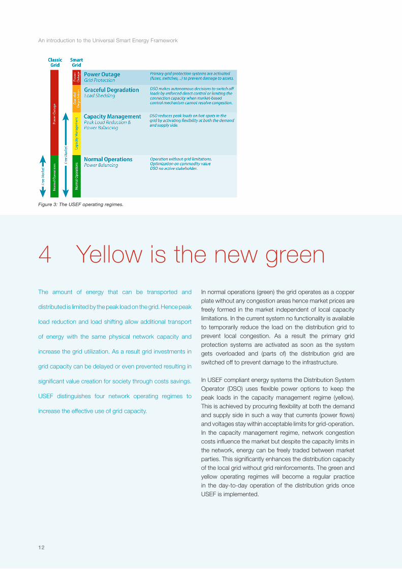
Figure 3: The USEF operating regimes.
The amount of energy that can be transported and
distributed is limited by the peak load on the grid. Hence peak
load reduction and load shifting allow additional transport
of energy with the same physical network capacity and
increase the grid utilization. As a result grid investments in
grid capacity can be delayed or even prevented resulting in
significant value creation for society through costs savings.
USEF distinguishes four network operating regimes to
increase the effective use of grid capacity.
In normal operations (green) the grid operates as a copper plate without any congestion areas hence market prices are freely formed in the market independent of local capacity limitations. In the current system no functionality is available to temporarily reduce the load on the distribution grid to prevent local congestion. As a result the primary grid protection systems are activated as soon as the system gets overloaded and (parts of) the distribution grid are switched off to prevent damage to the infrastructure. In USEF compliant energy systems the Distribution System Operator (DSO) uses flexible power options to keep the peak loads in the capacity management regime (yellow). This is achieved by procuring flexibility at both the demand and supply side in such a way that currents (power flows) and voltages stay within acceptable limits for grid-operation. In the capacity management regime, network congestion costs influence the market but despite the capacity limits in the network, energy can be freely traded between market parties. This significantly enhances the distribution capacity of the local grid without grid reinforcements. The green and yellow operating regimes will become a regular practice in the day-to-day operation of the distribution grids once USEF is implemented.
4 Yellow is the new green

13
In exceptional situations where the market is no longer able to maintain the network load within acceptable limits, USEF compliant networks start the process of graceful degradation (orange). Grid connections are (stepwise) limited in their connection capacity until the network load is within acceptable limits again. The DSO temporarily overrules the market in these situations to prevent a complete power outage (red). The DSO can differentiate its connection contracts by providing different levels of reliability to various types of end-users. Based on such contracts, priorities to limit the connection capacity are set which allows differentiating between clients who critically depend on energy and connections like public fast charging stations for electric vehicles which can be temporarily limited in their charging speed without any real damage. As soon as the system restores itself the market can take over again. The existing primary safety system continues to safeguard the energy infrastructure.
The market-based control mechanism and network operations are elaborated on in Chapters 8 and 9, respectively.

An introduction to the Universal Smart Energy Framework
14
Figure 4: Relations between the energy market and system control operation.
The transformation of consumers to active ‘up- and
downloaders’ has not been foreseen in the design of the
current energy system. The USEF Market-based Control
Mechanism (MCM) is set up in such a way that the
basic freedoms for all participants in the energy system
are supported and costs and benefits are allocated in a
transparent way. As a result all assets will be dispatched in
the most economical achievable way within the boundary
limits of the free market operating regimes of USEF: normal
operations and capacity management.
European guidelines and national legislative implementations are based on three basic market freedoms, which are an essential condition for the energy market liberalization and are:
Connection: every party has the right to be connected to the grid;
Transaction: parties have the right to engage in energy transactions with each other;
Dispatch: parties have the right to take from or feed energy into the grid at all times.
The transformation into a smart energy system is potentially at odds with these three basic freedoms. USEF provides a MCM that extends the free market to the regional, local and individual level, indicated in the USEF scope diagram (Chapter 2). It offers access to the energy market for all participants. They can freely dispatch their assets and by doing so all assets in the system effectively become a part of this energy market. The MCM provides a transparent cost allocation method distinguishing different prices for commodity, capacity and flexibility. The market facilitates dispatching all assets at the lowest costs and hence the MCM allows operating the system in the most economical achievable way. Since market prices are formed on
5 Democratizing the energy market

15
timescales down to the near real time domain rapid variations in supply and demand can be resolved in the market by continuously balancing supply and demand of energy. This becomes increasingly important with a growing share of intermittent renewable energy sources that under certain weather conditions generate power with large fluctuations that are hard to predict very accurately.
The introduction of local capacity tariffs during moments of congestion results in peak load reduction in affected areas. Consumers and producers respond to price signals by shifting or postponing their energy demand or production resulting in a reduction of grid load. This is known as demand response and provides additional sources of flexibility to the system.
An introduction to the Universal Smart Energy Framework
16
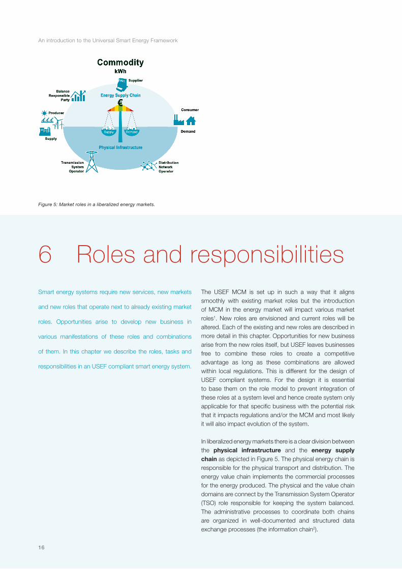
Figure 5: Market roles in a liberalized energy markets.
Smart energy systems require new services, new markets
and new roles that operate next to already existing market
roles. Opportunities arise to develop new business in
various manifestations of these roles and combinations
of them. In this chapter we describe the roles, tasks and
responsibilities in an USEF compliant smart energy system.
The USEF MCM is set up in such a way that it aligns smoothly with existing market roles but the introduction of MCM in the energy market will impact various market roles1. New roles are envisioned and current roles will be altered. Each of the existing and new roles are described in more detail in this chapter. Opportunities for new business arise from the new roles itself, but USEF leaves businesses free to combine these roles to create a competitive advantage as long as these combinations are allowed within local regulations. This is different for the design of USEF compliant systems. For the design it is essential to base them on the role model to prevent integration of these roles at a system level and hence create system only applicable for that specific business with the potential risk that it impacts regulations and/or the MCM and most likely it will also impact evolution of the system.
In liberalized energy markets there is a clear division between the physical infrastructure and the energy supply chain as depicted in Figure 5. The physical energy chain is responsible for the physical transport and distribution. The energy value chain implements the commercial processes for the energy produced. The physical and the value chain domains are connect by the Transmission System Operator (TSO) role responsible for keeping the system balanced. The administrative processes to coordinate both chains are organized in well-documented and structured data exchange processes (the information chain2).
6 Roles and responsibilities
17
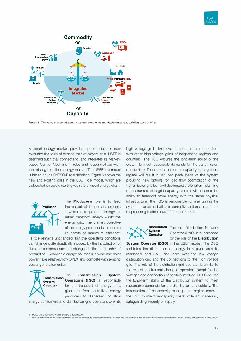
Figure 6: The roles in a smart energy market. New roles are depicted in red, existing ones in blue.
A smart energy market provides opportunities for new roles and the roles of existing market players shift. USEF is designed such that connects to, and integrates its Market-based Control Mechanism, roles and responsibilities with, the existing liberalized energy market. The USEF role model is based on the ENTSO-E role definition. Figure 6 shows the new and existing roles in the USEF role model, which are elaborated on below starting with the physical energy chain.
The Producer’s role is to feed the output of its primary process – which is to produce energy, or rather transform energy – into the energy grid. The primary objective of the energy producer is to operate its assets at maximum efficiency.
Its role remains unchanged, but the operating conditions can change quite drastically induced by the introduction of demand response and the changes in the merit order of production. Renewable energy sources like wind and solar power have relatively low OPEX and compete with existing power generation units.
The Transmission System Operator’s (TSO) is responsible for the transport of energy in a given area from centralized energy producers to dispersed industrial
energy consumers and distribution grid operators over its
high voltage grid. Moreover it operates interconnectors with other high voltage grids of neighboring regions and countries. The TSO ensures the long-term ability of the system to meet reasonable demands for the transmission of electricity. The introduction of the capacity management regime will result in reduced peak loads of the system providing new options for load flow optimization of the transmission grid but it will also impact the long term planning of the transmission grid capacity since it will enhance the ability to transport more energy with the same physical infrastructure. The TSO is responsible for maintaining the system balance and will take corrective actions to restore it by procuring flexible power from the market.
The role Distribution Network Operator (DNO) is superseded by the role of the Distribution
System Operator (DSO) in the USEF model. The DSO facilitates the distribution of energy in a given area to residential and SME end-users over the low voltage distribution grid and the connections to the high voltage grid. The role of the distribution grid operator is similar to the role of the transmission grid operator, except for the voltages and connection capacities involved. DSO ensures the long-term ability of the distribution system to meet reasonable demands for the distribution of electricity. The introduction of the capacity management regime enables the DSO to minimize capacity costs while simultaneously safeguarding security of supply.
1 Roles are embedded within ENTSO-e role model. 2 Van waardeketen naar waardenetwerk: oplossingen voor de organisatie van de Nederlandse energiemarkt, report drafted by Energy Valley for the Dutch Ministry of Economic Affairs, 2005.

An introduction to the Universal Smart Energy Framework
18
The role of the Consumer transforms into a Prosumer. Residential end-users and small and medium-size enterprises become active up- and
downloaders of energy. Prosumers offer their flexibility resulting from active demand and supply of energy to the (local) market. Empowered by insight services, they economically optimize the use of their assets.
A Balance Responsible Party (BRP) is responsible for actively balancing supply and
demand for its portfolio of producers and prosumers in the most economical way. Supply and demand must be continuously in balance. The BRP forecasts the energy demand of the prosumers in its portfolio seeks the most economical solution to supply the requested energy. The BRP can source the requested energy in two ways: directly by dispatching power plants with which it has a contractual agreement or indirectly via trading on the various energy markets. Trading on the imbalance market and supporting the TSO in maintaining the system balance can create additional value. USEF provides another degree of freedom to the BRP to optimize its portfolio: activating the flexibility in supply and demand that its prosumers offer.
The role of Supplier is to supply and invoice energy to its customers. The supplier agrees commercial conditions with its customers for the supply and
procurement of energy. USEF enables mass customization of customer propositions providing opportunities for product differentiation and brand recognition3.
The role of Aggregator consists of accumulating flexibility in active demand and supply. The aggregator seeks the lowest costs
to meet the energy demand of his portfolio taking the costs for capacity usage into account. USEF allows prosumers to directly access the market, but that case they implicitly act as the aggregator of their own portfolio. USEF is defined in such a way that accumulation of multiple aggregators into a larger aggregator is possible.
USEF distinguishes between an aggregator and an Energy Service Company (ESCo)4. The ESCo offers additional energy-
related services to end-users but is not directly active in the energy value chain or the physical infrastructure itself. The ESCo provides insight services as well as energy management services.
3 Understanding the roles and responsibilities in the USEF role model starts with understanding the rationale behind the contracts in the energy supply chain. The strict regulations for granting a supply permit on public networks are closely related to the collection risk and required financial stability to ensure that the supply of energy can be guaranteed. Since the supply of energy cannot be interrupted from a social point of view, end-users remain connected to the grid when a supplier goes bankrupt. In such an event, the financial risk would be carried by the remaining suppliers in the system.
4 Currently the role of ESCo is already recognized by the market, but note that the definition is often not completely in line with the definition of USEF.

19
New business opportunities arise for delivering new services
and propositions to the various stakeholders in smart energy
systems. The USEF role model is accompanied by a generic
interaction model that describes the relations between the
various roles active in the smart energy system.
In the interaction model the essential interactions between the various market roles are depicted. Each of these interactions is detailed by specific interactions in each phase of the MCM: plan, validate, operate and settle. Three contractual relations are made explicit in this interaction diagram since it seems essential for understanding this interaction model, but more contractual relations exist. To keep the diagram clear all relationships are depicted as 1-to-1 relations, but most of them have a 1-to-N relationship as described in the next section. A full description of the interaction model in all phases of MCM and the underlying contracts are provided in the USEF documentation.
Supplier and Prosumer (1-to-N)The contract for the supply of energy to the prosumers and vice versa has to be agreed between the supplier and prosumer. Although third parties can operate as a white label under the auspices of the supply permit of the supplier the responsibilities remain with the supplier. In the contract between the supplier and the prosumers the operating conditions for the demand response service executed by the aggregator acting under the flag of the supplier is defined as well. Note that the participation in
7 The USEF interaction model
Figure 7: The USEF interaction model.
An introduction to the Universal Smart Energy Framework
20
demand-response programs is not mandatory: consumers can decide to keep a profile-based contract.
Supplier and Aggregator (1-to-N)The supplier and aggregator sign a framework contract for all prosumers serviced by the aggregator. This framework contract defines the operating conditions for the demand response service executed by the aggregator acting under the flag of the supplier and corresponds with the conditions agreed between the supplier and prosumer.
Aggregator and Active demand and/or Supply at the prosumers (1-to-N)The aggregator controls the active demand and supply assets and appliances of the prosumers. MCM defines that the control by aggregator starts with forecasting the demand and supply profile of its prosumers. Based on this forecast and the expected flexibility the aggregator optimizes its complete portfolio.
Prosumer and its Active demand and/or supply (1-to-N)The end user controls the user settings of the smart energy appliances and assets that are controlled for demand response purposes by the aggregator. Note that these settings (might) influence the flexibility that these appliances and assets can offer to the aggregator.
BRP and Supplier (1-to-N)The supplier has a contract with the BRP that defines the commercial conditions under which the BRP sources the energy demand/supply of the portfolio of prosumers under contract with the supplier.
BRP and Aggregator (1-to-N)The aggregator and BRP negotiate on how to mutually optimize their portfolios and find the lowest operational costs.
BRP and Producer (1-to-N)Based on the portfolio optimization of the BRP, the BRP determines the most economical way to balance its portfolio. This process determines how much energy each power plant should produce in the upcoming period. The BRP orders the Producer to dispatch that amount of energy in the upcoming period. In the operate phase the BRP can request the producer to alter its production plan and change the
TSO and BRP (1-to-N)The TSO validates if the transport of the energy as expected by all BRPs (‘E-program’) connected to its grid can be executed reliably and safely. The TSO continuously monitors the network conditions and when imbalances arise the TSO buys power on the imbalance market from the BRPs to balance the system.
TSO and DSO (1-to-N)The TSO validates if the expected import / export of energy on the grid connections with the DSOs (‘T-program’) can be executed safely and reliably. If so the TSO will transport this energy from/to these grid connection points.
DSO and Supplier (1-to-N)The DSO formally agrees a framework contract with the supplier that defines the conditions under which the aggregator can negotiate the condition to provide flexibility to the DSO. These

21
conditions should be reflected in the framework agreement between the supplier and the aggregator.
DSO and Prosumer (1-to-N)The DSO validates that the expected amount of energy supplied and/or procured can be distributed safely and reliably to/from the prosumers as expected by the prosumer’s aggregator (‘D-program’). If so the DSO will distribute this energy from/to these prosumers.
DSO and Aggregator (1-to-N)In case the DSO expects congestion issues in its distribution grid the DSO will procure flexibility from all aggregators that actively offer flexibility to the DSO at that moment. This can be done either by ‘activation of flexibility options’ or by ‘procuring flexibility on a local market’ (Chapter 9). Operating conditions are formally covered by the framework contract between DSO and supplier.
ESCo and active demand and/or supply (optional) (1-to-N)The ESCo could offer remote maintenance services and/or insight services to the prosumers and hence he will retrieve data from the (active) demand and/or active supply assets and appliances of the prosumers.
ESCo and prosumers (1-to-N)The ESCo will provide insight information to the prosumers based on the insight service agreement and/or remote
maintenance of the prosumers active demand and/or active supply assets and appliances. These insight services could be used to influence the prosumers behavior and hence be a part of one or more flexibility services5. In the interaction model above existing trading processes between BRPs and others are not described in USEF, but remain operational in the market. This model would allow an aggregator of aggregators to exist as well.
7.1 Combination of roles in business modelsThere are three combinations of the supplier and aggregator that most likely will appear regularly in new business models, which are elaborated in this section6. Although this is an implementation issue and not part of the role/interaction model itself, for most people these combinations provide more clarity on these roles, their responsibilities and the interactions between them:1. Aggregator and Supplier as separate businesses
The role of aggregator and supplier are set-up as separate businesses and the aggregator optimizes the assets and appliances of a (specific) set of customers of the supplier or a specific set of assets. A typical example would be an aggregator of charging stations for electric vehicles that optimizes the charging process on behalf of the supplier.
5 One could argue that therefore this should be a part of the role of the aggregator. Since the response would be indirect and in business implementation these roles can be combined we have chosen to keep the insight service a pure role of the ESCo.
6 Note that business models with various combinations of the ESCo role that include ancillary services can be made (Chapter 10).

An introduction to the Universal Smart Energy Framework
22
2. Implementation of the aggregator role in the supplierThe supplier includes the role of aggregator in its own business and executes all tasks related to the role of aggregator itself. Existing suppliers are likely tempted to follow this path.
3. Outsourcing of the supply role to an aggregatorThe supplier outsources its tasks of contracting, invoicing and service customers to an aggregator. The contract between the aggregator and customer is based on a framework agreement between the aggregator and supplier and contains a reference to that framework agreement. This reference dictates that the energy supplied or procured from the customer is formally executed on behalf of the supplier. The regulator might require the aggregator to clearly communicate that its business is ‘powered by the supplier’ for reasons of transparency. A typical example of such a business would be a local energy company or community and the supplier might also provide a complete platform for contracting, invoicing and servicing customers to all aggregators operating under the flag of the supplier.

23
The USEF MCM facilitates the delivery of value propositions
(i.e. marketable services) to various market parties without
imposing limitations on the diversity and customization
of the propositions. The USEF MCM is designed for all
energy commodities including CO2 and enables the market
to optimize in time, capacity and power. MCM provides
access, under equal conditions, for all stakeholders to a
single integrated market. This unique approach aims for
a future-proof design of the energy market. Moreover it
will create the conditions for a sufficiently large and liquid
market for the trading for small-volume energy trading by
small players.
In order to facilitate the seven essential smart energy services (Chapter 10) and valorize the flexibility they provide in the distribution grid in a universal way, a new Market-based Control Mechanism (MCM) alongside with new processes needs to be put in place. The USEF MCM is set-up such that aligns smoothly with existing process in the current liberalized energy markets. A summary of these processes is provided with the USEF operations schema as depicted above. Since the USEF MCM is meant as an addition to the current liberalized market model most processes remain unchanged therefore will not be described by USEF. This chapter will focus on the new and market processes and describes where existing processes need to be altered. As clarified in Chapter 4 undisturbed market operation is possible in normal operations and capacity management regime. Hence the chapter only describes the processes of these operating regimes. The processes involved are grid operations are covered in Chapter 9.
8 Market-based Control Mechanism
Figure 8: USEF Operations scheme.

An introduction to the Universal Smart Energy Framework
24
The USEF MCM operations scheme distinguishes four steps and the corresponding processes can be summarized as follows:
Plan: In the planning phase the demand and supply of energy are forecasted for the upcoming period, usually a calendar day. Both the BRP and aggregator carry out an initial portfolio optimization.
Validate: In the validation phase the TSO and DSO validate if the demand and supply of energy can be transported and distributed safely without any limitations. If congestion occurs the TSO and DSO can procure flexibility from the market to resolve the congestion. This process is iterative with the planning phase until all plans can be carried out safely without any limitations.
Operate: In the operation phase the actual assets and appliances are dispatched and the TSO, BRP and aggregator jointly maintain the system balance and when needed the TSO and DSO can procure additional flexibility from the BRPs and aggregators to resolve unexpected congestions during the operations.
Settle: in the settlement phase the actual consumed and produced volumes are allocated to the responsible parties, unresolved or disputed volumes are reconciled shortly after and the supplier invoices the consumed and/or produced energy afterwards based on the contract with the end-user.
Each step is elaborated below and the full descriptions can be found in the USEF document.
The aim of the ‘Plan’ and ‘Validate’ phase are to make optimal use of the grid capacity and maximize the freedom of dispatch and transaction of all stakeholders in the grid. The time scale of the validation phase is ranging from already years and months ahead towards the main process day-ahead and ultimately one hour7 ahead in the intraday process before the ‘Operate’ phase starts. This time window supports trading on various energy markets and the monitoring of changes of the required network capacity.
8.1 PlanThe aim of this phase is to find an economically optimized program to supply the demand of energy of both the portfolio of the aggregators and BRPs for a certain period. The result of the aggregator is deflected in its ‘D-program’ similar to the current ‘E-programs’ of the BRPs, but the ‘D-programs’ take the grid topology into account as well. Note that ‘E-programs’ need to be in balance, which is not the case for the ‘D-programs’. The aggregator send its ‘D-program’ to the DSO for validation and the ‘E-program’ of BRP is send to the TSO for validation. This process is iterative and interfacing with the next phase ‘Validate’. These planning activities are subject to commercial processes, i.e. contractual agreements between end-users and aggregator on one side and aggregators, producers and BRPs on the other side.
7 USEF aims to shorten this period but practical experience from demonstration projects is needed to determine how far this limit can be stretched
25
The MCM starts when the aggregator creates a forecast, either from aggregating the forecasts from individual end-users or by forecasting itself in case the end-user outsourced his forecasting. The aggregator optimizes its own portfolio and plans how to maximize the value of the flexibility options in its portfolio. The aggregator sends a commodity request to the BPR.
Likewise the BRP optimizes its portfolio of aggregators, producers and trading of energy. During this optimization it will negotiate with its aggregator to exploit the available flexibility in the market and optimize its value. The aggregators are mutually obliged to keep their ‘D-programs’ and ‘E-program’ aligned. The resulting ‘E-program’ will form the basis for the allocation and reconciliation process.
USEF proposes to initially implement the procurement of flex power as a bilateral market between aggregators and BRPs, but most logically this will develop in a multi-lateral market in the long term.
8.2 ValidateThe step Validate exists of two intricately linked processes, executed in parallel by different market roles: ‘Validate D’ and ‘Validate E’ process. In these processes the (draft) ‘D-program’ and draft ‘E-program’ that result from the ‘Plan’ phase are validated against grid constraints by the DSO and TSO respectively.
In the ‘Validate D’ process The DSO accumulates the
‘D-programs’ of all aggregators active in his distribution network resulting in a ‘T-program’. The TSO validates if the ‘T-program’ can be carried out safely without any limitations. If congestions arise in the distribution grid the DSO will procure flexibility in the market to resolve these congestion issues. This process is iterative with the planning phase and as soon as all issues are resolved and all programs can be carried out safely. The DSO will send out a grid safety certificate to each aggregator and send out the resulting T-program to the TSO for verification.
The ‘Validate-E’ process is already in place in the current model. In this process the TSO accumulated the ‘E-programs’ from all BRP active in the network area of the TSO. The TSO validates if the accumulated plan can be carried out within the safety margins of the transmission system and finally checks is the results is in line with the T-programs received from the DSO connected to the transmission system. On top the TSO validates if the ‘E-programs’ of each BRP is in intrinsically balance.
If congestions occur on a transmission level the TSO as well can procure flex power to resolve congestion in the network. Again this is a common practice in most liberalized energy markets and hence not a part of the USEF process descriptions.
Note that the processes ‘Validate-E’ and ‘Validate-D’ are executed in parallel but are tightly linked since a change in a D-program most likely will lead to changes an E-program and to a lesser extent vice versa. Hence programs thus need to be validated iteratively until they converge within

An introduction to the Universal Smart Energy Framework
26
the constraints of the three basic freedoms mentioned at the start of Chapter 5.
8.3 OperateSimilar to the current liberalized energy market the system remains in balance without any congestion issues as long as no deviations from the validated ‘D-programs’, ‘E-programs’ and ‘T-programs’ occur. Effectively all appliances are dispatched as expected and the energy. However it is quite unlikely that all ‘D-programs’ and ‘E-programs’ are executed exactly. Deviations can arise from all sorts of sources ranging from deviations from the weather expectations to an extension of a football match. Deviations can lead to both imbalances in supply and demand of energy on total system level as well as local congestions can occur in the transmission system as well as in the distribution system. It should be noted that the accuracy of the forecasts will increase and hence will lead to a reduction of the commodity costs in the system.
The TSO will maintain the system balance and procure additional flex power for balancing purposes from the BRP on the imbalance market to compensate for imbalances detected. The aggregator can dispatch additional flex power options on request of the BRP. The BRP will try to maximize the economic value of the remaining flexibility in its portfolio by using it either for internal portfolio optimizations or trading it on the imbalance market.
Although the DSO will reduce congestion risks in the plan and validate phases, the DSO can still request aggregators
to dispatch flex power options to resolve congestion issues in the operate phase. However in such cases the portfolio of the corresponding BRP no longer will be in balance. As a result the aggregator will most likely charge additional cost to cover the imbalance risk to the DSO.
The operate phase takes place on PTU-level (currently 15 minutes) and the USEF MCM aims to shorten this period at least for the dispatch of flex power for balancing purposes to a minute level.
8.4 SettlementIn the operations phase the actual energy produced and/or delivered at each connection point are measured. These measurements are performed by certified parties in accordance with measurement codes and form the input for financial settlement between the stakeholders. The basis for both the allocation and reconciliation is formed by these measurements and the ‘E-program’ for all parties active in the energy supply chain. Potential differences between the ‘E-program’ and ‘D-program’ are a matter between the BRP and aggregator and can be settled based on mutually agreed conditions. The following settlement procedures will be covered by MCM:
Smart Allocation of the energy supplied and/or consumed at each connection point for parties with an interval meter and those with a flexible load profile e.g. with active demand and/or supply. This process includes settlement of imbalance costs.
27
B2B Settlement between the various B2B parties active in the smart energy market to settle the consumed and/or produced power including the procured flex power transactions between the DSO and aggregator.
Smart Billing of the energy supplied or consumed between the supplier and the party Connected to the Grid.
Smart Reconciliation of differences between estimated and actual energy consumption of profiled load/end-user in the grid, potentially incl. corrections of imperfections in the allocation process. With smart meters in place this process could be executed on much shorter timescales as the current practice of approximately 1½ years like in most liberalized energy markets without smart metering.

An introduction to the Universal Smart Energy Framework
28
An important aspect of the introduction of smart energy
systems is the operations of the energy infrastructure to
ensure an affordable, reliable and sustainable energy supply.
USEF describes how to reliably operate the distribution
grids in the newly introduced capacity management regime.
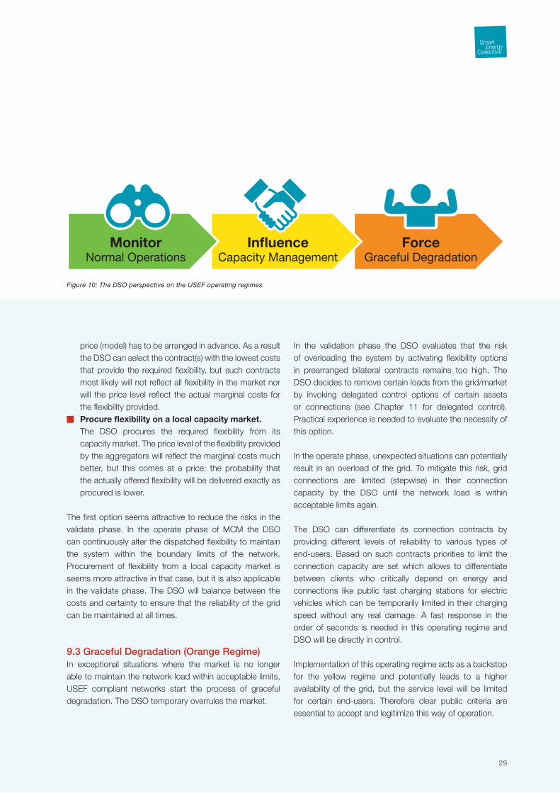
From a DSO perspective the following approach applies to each of the USEF operating regimes as described in Chapter 8:
9.1 Normal Operations (Green Regime)In the green regime sensors to measure the actual load flow and voltage levels in all areas where network congestion potentially can arise are essential to monitor the actual network conditions and predict where and when network congestion might arise. As long as no congestions are expected the DSO will not undertake any actions in the market.
9.2 Capacity Management (Yellow Regime)In the yellow regime continuous measurements are needed in all potential congestion areas to diagnose the actual network conditions. In areas where congestion arises the DSO will influence the market by procurement of flex power options in the market to keep the power flows and voltage levels within acceptable limits. To do so the DSO basically has two options:
Activation of flexibility options in prearranged bilateral contracts.
The reliability of this option is most likely high, but the
9 Grid operations
Figure 9: The grid operations highlighted.
29
price (model) has to be arranged in advance. As a result the DSO can select the contract(s) with the lowest costs that provide the required flexibility, but such contracts most likely will not reflect all flexibility in the market nor will the price level reflect the actual marginal costs for the flexibility provided.
Procure flexibility on a local capacity market. The DSO procures the required flexibility from its
capacity market. The price level of the flexibility provided by the aggregators will reflect the marginal costs much better, but this comes at a price: the probability that the actually offered flexibility will be delivered exactly as procured is lower.
The first option seems attractive to reduce the risks in the validate phase. In the operate phase of MCM the DSO can continuously alter the dispatched flexibility to maintain the system within the boundary limits of the network. Procurement of flexibility from a local capacity market is seems more attractive in that case, but it is also applicable in the validate phase. The DSO will balance between the costs and certainty to ensure that the reliability of the grid can be maintained at all times.
9.3 Graceful Degradation (Orange Regime)In exceptional situations where the market is no longer able to maintain the network load within acceptable limits, USEF compliant networks start the process of graceful degradation. The DSO temporary overrules the market.
In the validation phase the DSO evaluates that the risk of overloading the system by activating flexibility options in prearranged bilateral contracts remains too high. The DSO decides to remove certain loads from the grid/market by invoking delegated control options of certain assets or connections (see Chapter 11 for delegated control). Practical experience is needed to evaluate the necessity of this option.
In the operate phase, unexpected situations can potentially result in an overload of the grid. To mitigate this risk, grid connections are limited (stepwise) in their connection capacity by the DSO until the network load is within acceptable limits again.
The DSO can differentiate its connection contracts by providing different levels of reliability to various types of end-users. Based on such contracts priorities to limit the connection capacity are set which allows to differentiate between clients who critically depend on energy and connections like public fast charging stations for electric vehicles which can be temporarily limited in their charging speed without any real damage. A fast response in the order of seconds is needed in this operating regime and DSO will be directly in control.
Implementation of this operating regime acts as a backstop for the yellow regime and potentially leads to a higher availability of the grid, but the service level will be limited for certain end-users. Therefore clear public criteria are essential to accept and legitimize this way of operation.
Figure 10: The DSO perspective on the USEF operating regimes.
ForceGraceful Degradation
InfluenceCapacity Management
MonitorNormal Operations

An introduction to the Universal Smart Energy Framework
30
USEF defines seven essential services within a smart
energy system that drive the value creation and enable
peak load reduction, active balancing and providing insight.
The general services market and insight facilitate the five
flexibility services: demand response of smart appliances,
demand response of EV, management of local generation,
energy storage and energy management. In addition to
these essential services ancillary services can be developed
to improve the business case for smart energy systems.
10.1 General ServicesMarket serviceThe introduction of smart energy market service (1) based on USEF MCM enables the valorization of the flexibility provided by the flexibility services in a generic, transparent and uniform way. This is a crucial factor in the implementation of smart energy systems. It prevents that each new proposition would require a unique implementation in the market with its own requirements, market arrangements, interfaces etc. which would not be cost effective. Moreover it would result in a complex and opaque system that cannot be maintained in the long run. It allows the smart energy market to find the optimal achievable operating point for the system, while at the same time leaving each stakeholder free to translate his own proposition into a unique offering to his customers with his own price model.
Insight serviceThe insight service (2) is the second generic service enabling the flexibility services. It complements the market service and is driven by the data from the sensors and actuators in the smart energy system. The sharing of information provides a very attractive and efficient way to mutually generate value in the system and operate the connected assets in an optimal way. A multitude of attractive propositions can be built using this service, inviting stakeholders to become active participants in the smart energy system.
10 Services and propositions
Figure 11: The seven essential services.

31
The exchange of information via this and other services is governed by the USEF privacy & security guideline (Chapter 11) ensuring that it is implemented in a secure and socially acceptable way.
10.2 Flexibility ServicesThe flexibility services each provide flexibility in the load profile to the smart energy system in its own way. They allow shaping the load profile by shifting the load in time, buffering the energy or reducing the volume of energy needed. Each of these flexibility services is discussed in more detail in the next section.
Demand response smart appliancesDemand response (3) refers to influencing energy demand in response to incentives. Smart appliances are the appliances and assets that automatically react to these incentives. These incentives can be linked to the active market-based control mechanism by the aggregator and hence be dispatched based on the market conditions and hence support load management as well as active balancing. But this service could also support the process of graceful degradation.
Demand response electric vehicles (EV)Demand response of electric vehicles (4) is similar to demand response of smart appliances but applied to the charging of electric vehicles. The difference however is that this service may include both charging (and potentially also discharging) at the home or office and public charging at specific servicing points. This service takes into account other preconditions than demand response of smart appliances (mobility requirements of end users, vehicles that may charge at different locations, charging stations at home, and also ‘standalone’ charging stations directly connected to the grid); therefore this service is considered as a separate service.
Manage local generationSimilar to services 3 and 4 the manage local generation service (5) is focused on the flexibility provided by energy generation of local generation units. In this service it is important that these units respond in time to supply the required flexibility in the supply of energy. The incentive for providing this flexibility is related to the active market-based control mechanism. Flexibility in local energy production is necessary to match local demand and to keep the network in balance. Favorable energy prices on a market level can stimulate market players to provide flexibility locally in a
Figure 12: Example of a Business Canvas.
Business CANVAS Example: 2C-1 ESCO offers energy watch to end customer
Key Partners• Smartmetersupplier• Supplierofsmartplugs• SupplierofPV,μCHP,
HP, etc.• Combiwithdomotica?
Key Activities• Developenduser
product (HW)• Sales• DevelopSWservices
Value Proposition• Realtimeinsightin
energy usage• Realtimebill• Triggerswhenenergy
consumption pattern is deviating from normal pattern
• Energyusageofspecific devices
• Adviseonalternativeenergy products (e.g. PV,μCHP,HP)
• Alternativepricingschemes ‘Happy hour’
This proposition is an enabler for demand response services
Customer Relationships• Costumerbinding• Higherservicelevel
Customer Segments• Retailcustomer• Customerwhois
interested in energy consumption
• Customerwhoisinterested in gadgets
• Customerwhoisinterested in domotica services
• Customerwhoisinterested in costs
• SOHOcustomer
Key Resources• App• Homegateway• Wall-mounteddevice?• Smartplugs?
Channels• Mediamarktet.al.• Directshipping
Cost Structure• Productcosts(HW+SW)• Installationcosts• Servercosts(recurring)• Servicecosts(recurring)• Sales
Revenue Streams• HWsales• Monthlyfee• Extraenergysupplysales(expansionof
customer base)• Long-termcontractswithendcustomers
An introduction to the Universal Smart Energy Framework
32
similar way as this is now done on a national level (through emergency and reserve power an imbalance systems), however preferably through a simplified procedure. Topics that need to be explored in more detail here are reaction times, ramp up/down times, location requirements, availability requirements and the control mechanism itself.
Manage local storageStorage is a service (6) that can be used to manage peaks in demand and/or supply. Technical characteristics require that demand and supply of power need to be in continuous and almost instantaneous balance at all times. Although the power balance is principally maintained by market transactions, market imperfections and technical disturbances cause imbalances. These imbalances can either be resolved by making use of ancillary services (emergency and reserve power transactions) but local storage can also introduce new alternatives. When excess power can be stored locally to be reserved for periods when there is a local power shortage there will be less need for balance management actions. To appropriately enable this service it must be linked to the active market-based control mechanism.
Energy managementEnergy management (7) goes beyond providing insight. Energy management focuses on energy and cost savings for the end user. An energy management service is used to monitor, control, and optimize the performance of the energy system as a whole, within the constraints set by the end user. The flexibility gained by this service is offered to the market. These services are focused on the monitoring and optimizing of those appliances and facilities in a building or
facility that are relatively high in energy consumption such as heating, ventilation and lighting installations. The scope of these services may span from of a single building to a group of buildings such as office buildings, retail stores networks or factories. The energy management systems also provide facilities for the measurement of energy consumption. The acquired data can be used to perform analysis and optimization routines and to produce trend analyses and periodical consumption forecast
10.3 Ancillary Smart Energy ServicesVarious ancillary smart energy services can be delivered by the ESCo role in a smart energy system. These services can unlock latent residual value present in the smart energy system and increase the attractiveness of smart energy system. By broadening the ecosystem and attracting more parties not directly active in the energy value chain the overall business case can be improved and the viability of smart energy systems increases.
10.4 PropositionsPropositions are concrete offerings from one stakeholder (e.g. a supplier) another (e.g. its customer) that bring certain value to the customer, e.g., by fulfilling customer needs or solving a customer’s problem. Propositions are needed to materialize the seven essential services of USEF, i.e., transform them into value propositions for a specific customer. In most cases a cascade of propositions is required to implement one the essential services.

33
For example: a product supplier has a proposition towards end users by offering appliances with built-in demand response functionality, which is a proposition on its own. But there is no added value to this additional functionality if no corresponding flexible energy price product is offered that can exploit the demand response functionality and valorize the flexibility
For each of the propositions USEF provides a detailed description in the form of a business canvass and a use case. The business model canvas is used to describe the propositions in a general, comparable way. The canvasses provide a clear overview of the value proposition itself, the target customer segments, and activities needed to realize the proposition. Moreover it identifies the potential revenues and costs and thereby giving a basis for the business case of the proposition. It is a simple format to show players in the smart energy sector how certain propositions can be offered to the market and which partnerships are needed.
The use cases provide additional description for a given proposition. They focus on the interaction between stakeholders to realize a stakeholder’s goal, i.e., to realize a proposition. Besides better understanding of this interaction, the use cases serve as input for the USEF ICT infrastructure and the E-infrastructure.
During the process of defining the use cases it was recognized that all flexibility services and related propositions can be defined by a single use case that shows the complete interaction between all stakeholders to unleash the flexibility and bring value to all stakeholders.
All additional services like giving insight or organizing the market can also be described by business canvasses and use cases. However the use case for these propositions and services is not that complex as it is for the flexibility services. Therefore USEF focuses on the use case for the flexibility services. However, it is important not to forget additional propositions built using the market, insight and ancillary services: for the service providers in a smart energy system these propositions can be an important additional revenue stream.

An introduction to the Universal Smart Energy Framework
34
There are a number of options to support the dispatch of
assets of end-user installations and enable the flexibility
services. USEF distinguishes two different forms that enable
demand response that each has its own characteristics
and merits.
11.1 Soft ControlThe control of appliances and assets is performed by local control algorithms and the price is settled with the aggregator either in the validation phase and/or in the operate phase. This methodology has four major advantages over delegated control:
The control algorithms can access accurately the local status information and determine the most optimal solution and balance all relevant (local) parameters (comfort, costs, CO2 emissions, etc.) at that instance.
The way the price can be based on the marginal costs and hence the MCM can seek the most economic operating point for all assets in the system.
In-home optimization is possible, allowing optimize the energy portfolio of an end-users before offering the aggregated in-home flexibility to the market. This allows optimizing for price differences arising from tax costs, network costs, etc. as soon as energy is exchanged others.
Economic optimization takes place in the market time domain.
However these advantages come at a price: the control is indirect by price incentives and cannot be guaranteed on a device level. Although the overall response can most likely be predicted rather accurate for very local issues this might turn out to be insufficient in some cases.
11 Unleashing the flexibility
Figure 13: The information exchange between the aggregator and the home installation of end-user for delegated and soft control.

35
11.2 Delegated ControlThe control of the appliances and assets is delegated to the aggregator who can directly control these devices and shifts loads and/or use their internal buffers. In the green and yellow operating regime the aggregator will based on an internal optimization of its portfolio decide which units should be dispatched and send control signals directly to the devices of the end-user. Delegated control provides an (almost) guaranteed response, but it comes at a price as well:
The status information send to the aggregator will always be less accurate as the information that is locally available and hence determination of the most optimal solution that balances all relevant (local) parameters (comfort, costs, CO2 emissions, etc.) is always less accurate.
The way the price for dispatching has to be settled in advance (based on actual parameters), and since the accuracy of the status information is limited the price determination will also be less accurate. Moreover one could expect that end-users would somehow like to be compensated for the lack of control, most likely resulting in a higher price.
The economic optimization takes place over the full period of the contract.
In practice one most likely will find a combination of both control options. For the yellow and green regime both options are viable and even here combinations would be possible. In the validate phase a DSO can assure that certain assets will not overload the grid and hence contracts for direct control are called off. In the operate phase the remaining assets are optimized primarily for trading purposes. When
the DSO detects that the network load becomes too high additional flexibility can be dispatched to ensure that the system remains stable. During graceful degradation delegated control is the less intrusive option to achieve sufficiently fast reaction times and the control is delegated to the DSO in these situations. If delegated control appears to unleash insufficient flexibility, more intrusive options are needed e.g. limiting power at connections for example.
11.3 Different types of demand responseDemand response is the ability of appliances and assets to alter their operations and hence their energy consumption based on control signals. One can distinguish two types demands response:
Shiftable appliances: the appliance can shift its operations over time and hence provide a shifted load profile. Examples are washing machines and dishwashers where the end user defines e.g. the end time. Based on the control signal the wash machine starts operating and control logic is needed to ensure that the wash program finishes in time.
Interruptible appliances with buffering capability: based on the control signals the appliances are interrupted, the energy buffer provides flexibility in time to shift the load. Examples of such appliances are: heat pumps with heat storage and smart freezers.
Direct Control Soft Control
Appliances are controlled directly by the aggregator based on an agreement (contract).
Appliances react based on price settlement on local energy market.
Aggregator has to balance costs en benefits for flexibility provided for capacity and commodity based on fixed contract prices for direct control.
Behavior of appliances can be optimized locally and optimization can be based on all relevant parameters like marginal costs, comfort, etc.
Almost guaranteed response. Response based on collective behavior of the system. More advanced prediction and risk management algorithms are needed.
Low volatility on capacity and commodity market. Prices levels based on individual contracts. Aggregator and hence DSO cannot guarantee that the costs for capacity management are minimal.
High volatility on capacity and commodity market. Price levels settled based on market price formation. Aggregator and hence DSO can guarantee that cost for capacity management are minimized.
Contract forms are relatively simple and the settlement process is straightforward
Large variations of (mass customized) energy propositions for end-users are possible taking all relevant parameters for end-users into account.
Control without loss of comfort cannot be guaranteed. Control without loss of comfort possible.
Signals can be made available to influence consumer behavior but only a coupling between contract costs and behavior can be established.
Price signals are available to influence consumer behavior and a direct coupling between marginal costs and behavior can be established.
Standardization for interfaces between appliances and ESG are essential for market introduction.
Standardization for interfaces between appliances and ESG are essential for market introduction.
Modular design of the system, easy to expand and but application dependent solutions most likely will be developed.
Modular design of the system, easy to expand and application independent concept.
Table 1: Overview of delegated- and soft control.

An introduction to the Universal Smart Energy Framework
36
SEC partners aim to develop products, services and
solutions that together form a commercially viable smart
energy system. A common understanding of the value
creation in smart energy systems is needed to:
Design USEF such that all potential sources of value
can be unleashed;
Validate the model in USEF compliant demonstration
projects;
Support the development of the business case of each
of the SEC partners;
Support the development of the business case of the
demonstration projects.
For the latter purpose downscaling the outcomes to the
level of a demonstration project and vice versa is crucial to
gain insight in the business case at large scale deployment.
A typical pitfall would be trying to achieve a positive business
case at the scale of a demonstration project (under the
current market conditions).
12 Quantifying the value creation
Figure 14: Example of the results of the tool.
-0.06 -0.04 -0.02 0.00 0.02 0.04 0.06 0.08
Reduction grid loss cost
Potential CPP peak reduction value
Potential imbalance market value
Reduction LV-grid capacity cost
Reduction MV-grid capacity cost
Reduction HV-grid capacity cost
Reduction electricity generation cost
Reduction generating capacity cost
Total net present value [Meuro]
Smart grid value

37
A value creation model is developed that allows to analyze the value creation of the flexibility on the different markets and scenarios, to evaluate the influence of several parameters, to make a comparison of different services and also to understand the impact of national developments on the business case for a local smart energy system.
The model is available for all SEC partners to gain insight in the value creation in USEF compliant system and analyze (self-defined) scenarios and it is currently preloaded with Dutch market data. The current model has three main limitations:
It does not quantify non-energy values of insight or ancillary services.
It does not quantify the costs of USEF compliant products and services.
Attribution of created values to the various roles.These values and costs are crucial elements for the business case for each SEC partner itself and for the business case of the demonstration projects as well. However a common understanding of these values is not crucial for SEC and leaves sufficient freedom for competence between the partners and demonstration projects.
12.1 The value creation modelUSEF compliant flexibility services change the load profile of active demand and supply assets and appliances of prosumers. As elaborated on in Chapter 3, the value created by the flexibility services result from peak load
reduction on the transmission and distribution grid as well as active balancing. Figure 14 shows an example of the typical output of the modes and the sources of potential value creation of the model.Figure 15 shows the steps required to calculate the value creation. The selected national scenario describes the developments at a national scale e.g. total amount of renewable, total energy demand etc. The user creates a local scenario that specifies the characteristics of the community where the services will be applied and the scenarios for the penetration of various technologies in that community.
Both scenarios and the effect of the flexibility services on the load profiles result in yearly load profiles that determine the yearly costs of electricity.
The current model is not a dynamic simulation model but it models the value creation by assuming static changes in load profiles8. Although it limits the accuracy of the results of the model it still provides a rich source of insights in the effects of the energy system. The tool can be used to run several profiles, to analyze the impact of changing the profiles and to make a sensitivity analysis of various scenarios.
Figure 15: Basic workflow of the value creation tool.
8 Extension of this model to a dynamic simulation tool is a budgetary issue and not a technical one.
Calculatevalue creation
Specifylocal scenarios
Selectnational scenario

An introduction to the Universal Smart Energy Framework
38
The introduction of Smart Grids will see an explosion of
the amount of captured energy usage data, from which
a wealth of personal information can be distilled. Smart
energy systems – like most complex information systems
– deal with sensitive data and therefore require security
and privacy preservation measures. Privacy and security
are system-wide issues; the protection of individual
subsystems/components is not enough. The system is
as strong as the weakest link and realizing a sufficiently
large market for smart energy products and services is not
possible when privacy & security issues undermine end-
user trust in the Smart Grid. USEF is therefore designed
with privacy & security in mind.
Privacy and security are distinct but related entities. Security is an essential foundation for managing privacy. You must implement security to ensure privacy. The security objectives of energy grids differ from most of the other industries. For energy grids, it is of the utmost importance that security measures do not adversely affect the availability of the grid. For energy grids, availability is the main security goal, followed by integrity. The final security goal is confidentiality. In smart energy systems, there are parts where confidentiality is more important, such as personal data and market information.
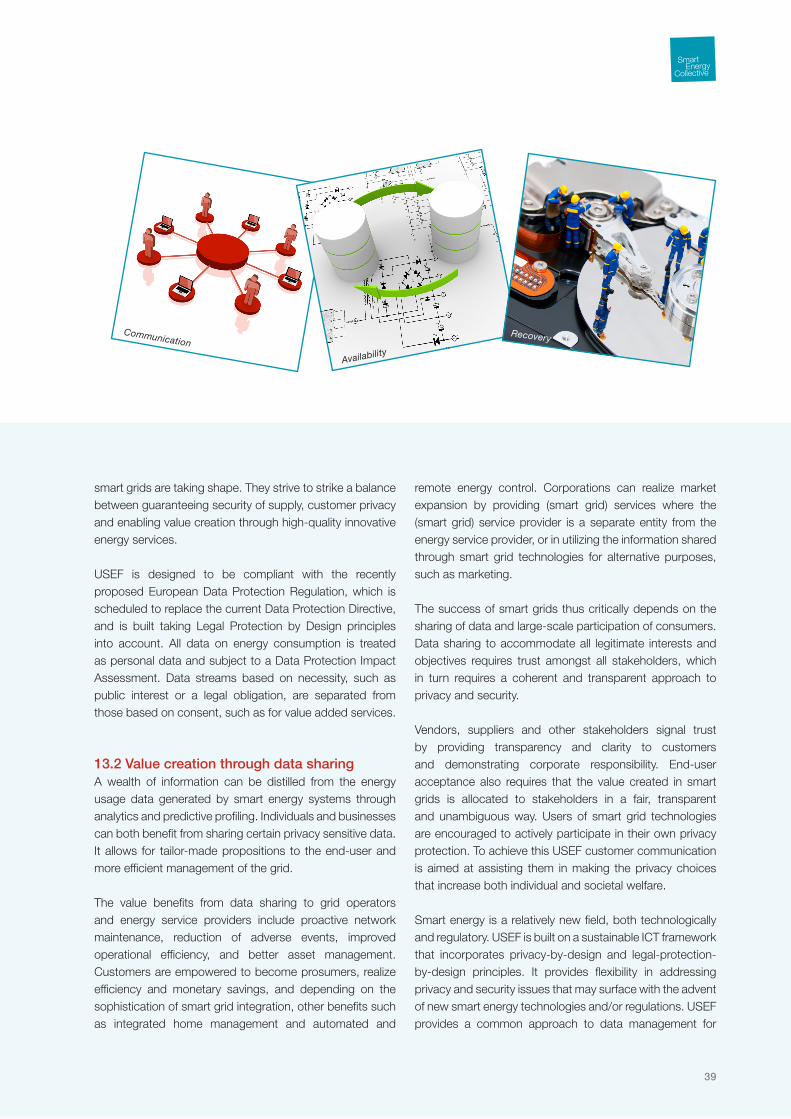
USEF contains a Privacy & Security Guideline structured around nine “windows” on privacy and security, depicted in Figure 16, that together present a complete view on the privacy and security aspects associated with smart energy systems. The guideline forms the basis for the logical security architecture that is part of the ICT framework. Essential insights from the guideline are shared below.
13.1 Legal frameworkA multitude of (international) regulations are being developed that address privacy and security aspects of smart energy systems, capturing society’s views on the benefits and risks of systems collecting and analyzing vast quantities of data. These regulations form the backdrop against which
13 Privacy & Security
Figure 16: The nine windows on privacy and security.
Privacy-value creation trade-offs Data management
Confidentiality
39
smart grids are taking shape. They strive to strike a balance between guaranteeing security of supply, customer privacy and enabling value creation through high-quality innovative energy services.
USEF is designed to be compliant with the recently proposed European Data Protection Regulation, which is scheduled to replace the current Data Protection Directive, and is built taking Legal Protection by Design principles into account. All data on energy consumption is treated as personal data and subject to a Data Protection Impact Assessment. Data streams based on necessity, such as public interest or a legal obligation, are separated from those based on consent, such as for value added services.
13.2 Value creation through data sharingA wealth of information can be distilled from the energy usage data generated by smart energy systems through analytics and predictive profiling. Individuals and businesses can both benefit from sharing certain privacy sensitive data. It allows for tailor-made propositions to the end-user and more efficient management of the grid.
The value benefits from data sharing to grid operators and energy service providers include proactive network maintenance, reduction of adverse events, improved operational efficiency, and better asset management. Customers are empowered to become prosumers, realize efficiency and monetary savings, and depending on the sophistication of smart grid integration, other benefits such as integrated home management and automated and
remote energy control. Corporations can realize market expansion by providing (smart grid) services where the (smart grid) service provider is a separate entity from the energy service provider, or in utilizing the information shared through smart grid technologies for alternative purposes, such as marketing.
The success of smart grids thus critically depends on the sharing of data and large-scale participation of consumers. Data sharing to accommodate all legitimate interests and objectives requires trust amongst all stakeholders, which in turn requires a coherent and transparent approach to privacy and security.
Vendors, suppliers and other stakeholders signal trust by providing transparency and clarity to customers and demonstrating corporate responsibility. End-user acceptance also requires that the value created in smart grids is allocated to stakeholders in a fair, transparent and unambiguous way. Users of smart grid technologies are encouraged to actively participate in their own privacy protection. To achieve this USEF customer communication is aimed at assisting them in making the privacy choices that increase both individual and societal welfare.
Smart energy is a relatively new field, both technologically and regulatory. USEF is built on a sustainable ICT framework that incorporates privacy-by-design and legal-protection-by-design principles. It provides flexibility in addressing privacy and security issues that may surface with the advent of new smart energy technologies and/or regulations. USEF provides a common approach to data management for
Communication
Availability
Recovery

An introduction to the Universal Smart Energy Framework
40
all its participants that is based on risk analyses and built around the “need to know” security principle, focusing on maximizing value creation by establishing trust.
13.3 Identification, authentication, authorization and trustIn a smart energy system, transaction supply and demand come together in a way to reach a desired optimum. Optimal may mean lowest possible financial cost, lowest environmental impact, maximum profit, or optimal resource utilization or other desired and defined goal.
To ensure the envisioned outcome of a transaction, there must be trust between participating actors as in any real-world transaction. Trust means that each actor will fulfill the promise of the transaction, that is produce or consume the agreed amount of energy at the agreed time and –where applicable- fulfill other (e.g., financial) obligations associated with the transaction. Trust will raise the likelihood that actors will continue to participate in future transactions benefitting the system, and that the system will engage enough actors for it to be able to function as a whole.
Trust is enhanced when the identity, authenticity and/or authorization of actors is known and verified. Trust is negatively impacted when actors cannot rely on the authenticity of actors, i.e., when identities can be abused (stolen, faked), when transactions cannot be properly authorized, or when transaction are not within preset (agreed upon) limits. Trust is further enhanced when the actual transactions are also carried out satisfactorily: behave as
agrees upon. Transparency of the trustworthiness of actors thus may also enhance the system, e.g. by evaluating or rating actors (e.g., suppliers, prosumers or device types) within the context of a transaction or even publically: rating is “explicit trust”. The USEF security guideline provides principles to address these issues. The use of Privacy Enhancing Technologies when dealing with identities balances the privacy and the trust needs of a Smart Energy System. The use of unique identifiers, provided by Smart Energy Identity Providers is recommended to reach economies of scale. Also, principles guiding the design and the implementation of authorization and rating systems are provided.
13.4 Data management and communicationUSEF provides a common approach to data management for all its participants that is based on risk analyses and built around the “need to know” security principle, focusing on maximizing value creation by establishing trust.
In smart energy systems, various and complex relations between Confidentiality, Integrity and Availability exist. As an example, the likelihood of power outages is expected to be related to the integrity of the exchanged data. Incorrect data or no data at all (when data exchange itself is unavailable) may thus lead to unavailability of the grid. With the introduction of smart grids a dependency between the availability of the power grid itself and the availability and integrity of the supporting ICT systems is introduced. USEF describes Confidentiality, Integrity and Availability in the
Identification, Authentication,
Authorization
Risk management
Integrity

41
context of smart energy systems and establishes principles that address their dependencies.
The focus on a risk analysis-based approach ensures that the measures to protect data are always proportional to the potential damage incurred by a privacy or security breach. It also implies that no one-size-fits-all recommendations on encryption levels, data retention times and redundancy levels are given as they depend on the outcome of risk analyses that may include subjective and context-sensitive quantifications of risks. USEF contains a sample risk analysis as well as recommendations for risk analysis methodologies.
All data managed by USEF should be subject to a data policy that specifies, at a minimum, who owns the data, why it is in the system, how it can be accessed and what its lifetime is. The use of explicit data policies provides transparency to all stakeholders and is an enabler for trust.
The requirements for communication in smart grids do not differ from other data communication networks such as the Internet. USEF ensures end-to-end protection of data streams against network attacks by protecting the data through encryption and avoiding transport nodes where data need to be disclosed, rather than protecting access to the medium only.
13.5 RecoveryWhen things go wrong, we are faced with the need for recovery, be it from a confidentiality breach, reputation damage (due to a lack of integrity) or availability failure. An important aspect of recovery is designing a smart energy system in such a way that it can predictably and reliably recover. In addition to the technical aspects (switching to backup systems, etc.), USEF provides guidance on communication and recovery planning: create a recovery plan, define priorities, publish it, keep it up to date and test it.

An introduction to the Universal Smart Energy Framework
42
A common view on the system architecture and
standardization of interfaces between the various
components of the system is essential to achieve the
desired interoperability and allow independent evolution
of the system components. It stimulates innovation and
competition between both technology providers as well as
stakeholders active in the energy value chain.
USEF has adopted The Open Group Architecture Framework (TOGAF®). This framework provides a comprehensive approach for designing, planning, implementing, and governing enterprise information architecture. TOGAF models the architecture at four levels: Business, Application, Data, Technology and Security. The USEF architecture is technology and implementation agnostic. It standardizes the logical interfaces and defines the minimum functionality of the components.
Using the TOGAF methodology the ICT architecture is defined at an increasing level of detail, starting with a high-level architecture vision. Currently the USEF architecture is defined to the level of the logical information systems architecture, i.e. activity C in the TOGAF diagram.
In phase A, the architecture vision, the stakeholders, scope, business values and capabilities have been identified. Each of them is described in the preceding chapters.
In phase B, the capabilities mandated by stakeholders within scope of USEF are combined into a business architecture. The required business functionality is mapped onto the business model. The business model reflects a modular approach where SEC partners can develop components independently. Jointly these components form a fully
14 ICT Architecture
Figure 17: The TOGAF model.
A.Architecture
Vision
Preliminary
H.Architecture
ChangeManagement
G.Implementation
Governance
F.MigrationPlanning
E.Opportunities
andSolutions
D.TechnologyArchitecture
C.Information
SystemsArchitectures
B.Business
Architecture
RequirementsManagement
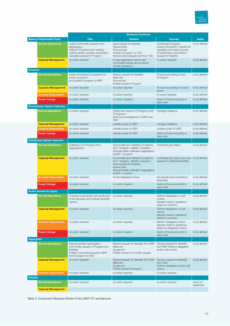
43
Table 2: Component Business Model of the USEF ICT architecture.
Business Functions
Balance Responsible Party Plan Validate Operate Settle
Normal Operations collect commodity requests from aggregators, collect E Programs from existing market parties, portfolio optimization,calculate balanced E Program.
Issue request for flexibilityReceive bids,Procure bids,Publish E program to TSOReceive acknowlegdement from TSO,
monitoring E program,receive and perform request for regulating and reserve power, if needed issue and perform request for flexibility
to be defined
Capacity Management no action required In case aggregator sends new commodity request act as during normal operations.
no action required to be defined
Producer
Normal Operations makes schedules (E-programs) for power productionand publish E program to BRP.
Receive request for flexibilityMake bidProcure bidPublish revised E Program
Produce according to final E Program
to be defined
Capacity Management no action required no action required Produce according to reserve power
to be defined
Graceful Degradation no action required no action required no action required to be defined
Power Outage no action required no action required Switch off load and perform black start
to be defined
Transmission System Operator
Normal Operations no action required Collect and check of E Programs andT-Programs,Send acknowledgement to BRP and DSO
manage imbalance to be defined
Capacity Management no action required outside scope of USEF manage imbalance to be defined
Graceful Degradation no action required outside scope of USEF outside scope of USEF to be defined
Power Outage no action required outside scope of USEF Switch off load and perform black start
to be defined
Distribution System Operator
Normal Operations Collection of D-Program from Aggregator(s),
Accumulate and validate D programs into T program, validate T program.send grid safety certifcate to aggregators,publish T program
monitoring grid status to be defined
Capacity Management no action required Accumulate and validate D programs into T program, validate T program,Issue request for flexibility,receive bids.send grid safety certifcate to aggregators,publish T program
monitoring grid status and issue request for additional flexibility
to be defined
Graceful Degradation no action required invoke delegated control De-activate grid connections (stepwise)
to be defined
Power Outage no action required no action required Switch off load and perform black start
to be defined
Active demand & supply
Normal Operations Forecast consumption and production of the device(s) and Forecast flexibility (option)
no action required Perform delegated- or soft control,dispatch asset or appliance based on incentive
to be defined
Capacity Management no action required no action required Perform delegated- or soft control,dispatch asset or appliance based on incentive
to be defined
Graceful Degradation no action required no action required Perform delegated control,dispatch asset or appliance based on delegated control
to be defined
Power Outage no action required no action required Switch off load and perform black start
to be defined
Aggregator
Normal Operations Internal portfolio optimization, Commodity request, D Program and flexibility,Publish commodity request to BRP and D program to DSO
Receive request for flexibility from BRPMake bidAccept bidPublish revised commodity request.
Receive request for flexibility from BRP, Perform delegated and/or soft control
to be defined
Capacity Management no action required Receive request for flexibility from DSOMake bidAccept bidPublish revised D program.
Receive request for flexibility from DSO, Perform delegated- and/or soft control
to be defined
Graceful Degradation no action required no action required no action required
Supplier
Normal Operations no action required no action required no action required carry out settlement
Capacity Management

An introduction to the Universal Smart Energy Framework
44
functional smart energy system. The business architecture provides an overview to SEC partners with opportunities to develop USEF complaint products, services and solutions. The business architecture is summarized in a Component Business Model (Table 2) describing the business functions needed for the roles defined in Chapter 6 for each phase of USEF MCM.
In phase C, the information system architecture (currently in progress), the application and data architectures are defined. The information system architecture focuses on the interaction between all the components in all levels of the system. They are defined in a number of low-level use cases, ranging from automatic service discovery by an appliance to settlement of energy transactions. An example of an UML sequence diagram describing such a use case is shown in Figure 19.
14.1 Supporting frameworkUSEFs ICT architecture also defines a supporting framework. The supporting framework is an ancillary component of the architecture that provides data collection and analysis services. These services are considered instrumental for evaluating and comparing the results in the various demonstration projects that USEF is used in. Providing such a common framework furthers the learning from demonstration projects and enhances the value creation of USEF.
14.2 Shared infrastructureIt is foreseeable that a (partial) implementation of the USEF ICT architecture will be realized to provide a shared infrastructure for the demonstration projects. Such a shared infrastructure will help to create and validate a reference implementation of USEF and reduce implementation costs for the demonstration projects.
Figure 19: Example UML sequence diagram.
DSO ServiceHome GatewayService
BRP ServiceEV
User
(from Actors)
1.0 imbalance ()1.1 dispatchFlexPower()
1.3 reduceChargeCurrent()
1.2 dispatchFlexPower()
1.4 notify()
sd Operate Phase
2.0 receiveProgram()
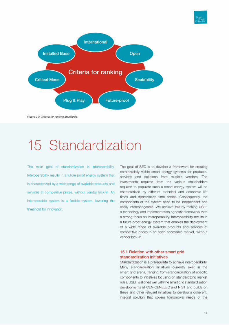
45
The main goal of standardization is interoperability.
Interoperability results in a future proof energy system that
is characterized by a wide range of available products and
services at competitive prices, without vendor lock-in .An
interoperable system is a flexible system, lowering the
threshold for innovation.
The goal of SEC is to develop a framework for creating commercially viable smart energy systems for products, services and solutions from multiple vendors. The investments required from the various stakeholders required to populate such a smart energy system will be characterized by different technical and economic life times and depreciation time scales. Consequently, the components of the system need to be independent and easily interchangeable. We achieve this by making USEF a technology and implementation agnostic framework with a strong focus on interoperability. Interoperability results in a future proof energy system that enables the deployment of a wide range of available products and services at competitive prices in an open accessible market, without vendor lock-in.
15.1 Relation with other smart grid standardization initiativesStandardization is a prerequisite to achieve interoperability. Many standardization initiatives currently exist in the smart grid arena, ranging from standardization of specific components to initiatives focusing on standardizing market roles. USEF is aligned well with the smart grid standardization developments at CEN-CENELEC and NIST and builds on these and other relevant initiatives to develop a coherent, integral solution that covers tomorrow’s needs of the
15 Standardization
Figure 20: Criteria for ranking standards.
Criteria for ranking
International
Open
Scalability
Installed Base
Critical Mass
Future-proofPlug & Play

An introduction to the Universal Smart Energy Framework
46
energy markets and the energy infrastructure. SEC takes a pragmatic, practical approach towards the development of USEF to enable vendors to develop commercially viable solutions.
15.2 The smart grid ecosystem of standardsA framework for creating commercially viable multi-vendor solutions should allow for a flexible yet coherent implementation of its logical components. This requires an ecosystem of standards that guarantees the interoperability of the components, provides multiple ways to connect them into a fully functional system and is thus free of ‘choke points’ that could lead to technology lock-in.
15.3 Building the ecosystemThe number of standards related to smart grids is truly staggering: for the in-home domain alone already 6000 relevant standards have been identified. Evaluating every relevant standard for every component is simply not feasible – a practical approach has to be taken and a pre-selection of standards has to be made.
SEC has mapped a large number of existing standards onto the functional domains covered by USEF. These standards have subsequently been rated and ranked based on eight criteria, shown in Figure 20 and briefly described Table 3. These rating criteria have a weight factor, indicating that some criteria are more important than other. The result of this process is a ranked set of standards that together cover all aspects of smart energy systems covered by USEF: the
USEF ecosystem of standards. In each iteration of building the ecosystem the aggregation score has to be reevaluated, which can influence the aforementioned ranking.
15.4 Tried and trustedThe ecosystem of standards will be tested and refined in the five large-scale demonstration projects that are currently under development in the Netherlands. In these demonstration projects the interchangeability and interoperability of various implementations of USEF building blocks will be demonstrated.
The standardization efforts of SEC ultimately result in a recommended practice for creating interoperable components for a commercially viable smart energy system.
Table 3: Explanation of the criteria used to rank and select standards.
Criterion Description criteria
International The standard is valid for all regions of the world, without conflicting standards for specific regions.
Open No royalties to be paid for applying the standard.The source codes are available for making extensions.
Scalability The standard is applicable to real-life implementations without limitations to the number of implementations.
Future-proof The standard can be used for technologies foreseen for the coming 10 years, and can be extended afterwards without breaking backwards compatibility.
Plug & play The standard can be implemented with self-configuration for the intended applications in the SEC framework.
Critical Mass The parties driving the standard together have a dominant share in the market.
Installed base The standard is already applied for > 3 years in >10 real-life implementations with a scale > 2500 assets.
Aggregation The standard has been successfully used in conjunction with other standards relevant for the smart energy systems.
47
The validation of USEF in practice is an essential step
towards large-scale market introduction of smart energy
systems. USEF compliant demonstration projects cannot
only support the promotion of the USEF framework but also
supports detailing the many aspects of USEF. Technology
and implementation choices do have to be made in practice.
Demonstration projects will provide insight in what fits best
with the aims of the USEF and SEC as a whole in mind.
A full-fledged demonstration of a USEF-compliant smart energy system is essential to convince various stakeholders and show how the envisioned smart energy systems look in practice. By actively involving end-users we learn what drives them to become active ‘up- and downloaders’ of energy and gain insight in their needs and requirements for smart energy products and services. Hence demonstration project provides a rich source of information and insights for the improvement and perfection of USEF.
Although the USEF design is implementation and technology agnostic demonstration projects are essential to make the step from the conceptual, functional and logical design level of USEF towards practical implementations. Technology choices have to be made in the development process of USEF compliant products. Demonstration projects provide testing and demonstration environments for these USEF compliant products and services and allow for the validation of their functionality and interoperability.
Large-scale demonstration is not only essential to commoditize the USEF compliant smart energy services, products and solutions but also to validate the business case parameters and various hypotheses behind the
16 Improve, Rinse and Repeat

An introduction to the Universal Smart Energy Framework
48
design of USEF. The validation of the business case is essential for both the commercial success of USEF itself as well as the demonstration project itself. To summarize, demonstration projects will pave the way towards future proof, cost effective interoperable smart energy systems.

49
It is with great pleasure that the Smart Energy Collective
(SEC) presents this summary of its Universal Smart Energy
Framework (USEF). It reflects the result of two years of
intense collaboration, resulting in the essential insight in
how smart energy systems should work, how they add
value to the energy system in a transplant and uniform way,
which roles, processes and technologies are relevant and
how they ultimately link up to form a consistent design for
the “new order” in the energy market.
USEF is unique in that it provides an integral and consistent approach for developing commercially viable products, services and solutions that jointly form thriving smart energy systems. It forms a solid basis for the future activities of SEC and the product and service development by its partners, soon ready to be demonstrated in various demonstration projects inside and outside SEC. USEF will provide an essential competitive edge for all of the partners involved.
With this first release of USEF we are gearing up to share our insights with others in the international smart energy arena. We are ready to validate that the model is as universal as we assume it is; ready to verify that all stakeholders that are, or soon will become, active in smart energy systems recognize the relevance of USEF for their business and see the added value it provides. We will be establishing partnerships with comparable initiatives and find new partners to complete our solutions and broaden our base before the large-scale roll out.
Acknowledgements

An introduction to the Universal Smart Energy Framework
50
We thank all partners and their representatives for their contributions, the discussions and willingness to share their views, expertise and knowledge that was essential to produce this unique body of work. Without them USEF would not be as universal and consistent as it is today.
Marcel VolkertsFrits VerheijFrits Bliek
Working group Market Control MechanismKlaas Hommes (chairman), Peter van der Sluijs, Joel Hoeksema, Harry Arts, Gerrit Rentier, Hans de Heer, Marcel Eijgelaar, Wessel Sluis, Martijn Maandag (secretary).
Working group ServicesMarten van der Laan (chairman), Thiemo Nieuwenhuizen, Henk Huisman, Jasper Ijzenbrandt, Michiel Kuiper, Anne Pieter Haytema, Lex James, Petra de Boer (secretary).
Working group Energy InfrastructureMaarten van Blijderveen (chairman), Michella Weverink, Martijn Bongaerts, Simon Kamerbeek, Peter Vaessen, Walter van Genderen, Pieter Kropman (secretary).
Working group ICT infrastructureArnoud Backers (chairman), Frank Geerts, Jorgen van der Velde, Jeroen van Meel, Hans Beerman, Pieter Bos, Hugh Maaskant, Peter Hermans, Wolf Freudenberg (secretary).
Working group Privacy & SecurityMilo Broekmans (chairman), Wouter Teensma, Anne Spoelstra, Philippe Smadja, Marco Leenen, Timo van Roermund, Marcel Volkerts (secretary).
Working group StandardizationHerman Leenders, Elif Karatay (secretary).

www.smartenergycollective.com