Embed Size (px)
Citation preview

An Approved Continuing Education Provider
PDHonline Course C727 (2 PDH)
An Introduction to Water Distribution
System Appurtenances
J. Paul Guyer, P.E., R.A.
2014
PDH Online | PDH Center
5272 Meadow Estates Drive
Fairfax, VA 22030-6658
Phone & Fax: 703-988-0088
www.PDHonline.org
www.PDHcenter.com

www.PDHcenter.com PDHonline Course C727 www.PDHonline.org
©2014 J. Paul Guyer Page 2 of 33
An Introduction to Water Distribution System
Appurtenances
J. Paul Guyer, P.E., R.A.
CONTENTS
1. VALVES AND HYDRANTS
2. INSTRUMENTATION AND CONTROLS (I&C), AND WATER
METERS
3. CROSS-CONNECTION CONTROL AND BACKFLOW PREVENTION
(This publication is adapted from the Unified Facilities Criteria of the United States
government which are in the public domain, have been authorized for unlimited
distribution, and are not copyrighted.)
(Figures, tables and formulas in this publication may at times be a little difficult to read,
but they are the best available. DO NOT PURCHASE THIS PUBLICATION IF THIS
LIMITATION IS NOT ACCEPTABLE TO YOU.)

www.PDHcenter.com PDHonline Course C727 www.PDHonline.org
©2014 J. Paul Guyer Page 3 of 33
1. VALVES AND HYDRANTS
1.1 OVERVIEW. This discussion covers the operation and maintenance of various
types of valves. It also addresses hydrant O&M, safety, and testing.
1.2 VALVES AND VALVE OPERATION. Valves are used in water supply systems to
start and stop flow, to throttle or control the quantity of water, to regulate pressures
within the system, and to prevent backflow. Valves are typically operated using
manual, electrical, hydraulic, or pneumatic operators. Most valves used in water
systems fall into one of the following general valve classifications: gate, globe, needle,
pressure relief, air/vacuum relief, diaphragm, punch, and rotary. The type of valve and
the method used to operate it depends on the use of the valve, its function in the water
system, and the source of energy available.
1.2.1 VALVE OPERATION
1.2.1.1 MANUAL OPERATION. Small valves or valves that are used infrequently are
generally operated manually. Valves operated manually should be opened all the way,
then closed one-quarter turn of the handwheel. This prevents the valve from sticking in
the open position. Open and close the valve slowly and at an even rate to reduce the
hazard of a hammer. Unless otherwise indicated, valves are opened by turning the
handwheel or key counterclockwise. Always consult the manufacturer’s instructions for
operating a specific type of valve. It is good practice to operate (exercise) valves
periodically.
1.2.1.2 POWER OPERATION. Only minimal attention is required for operating power
operated valves, except in the case of power failure. In this event, consult the
manufacturer’s instructions for emergency manual operation. Most power-operated
valves are equipped with safety devices to allow for emergency manual operation.
www.PDHcenter.com PDHonline Course C727 www.PDHonline.org
©2014 J. Paul Guyer Page 4 of 33
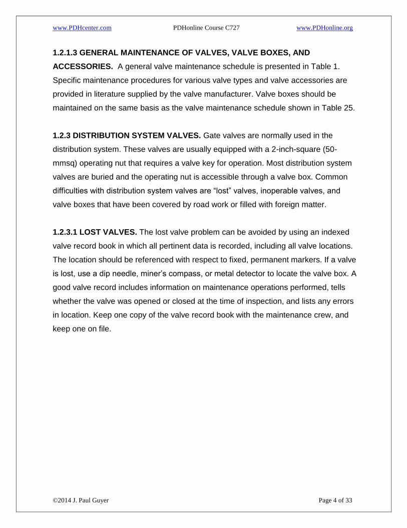
1.2.1.3 GENERAL MAINTENANCE OF VALVES, VALVE BOXES, AND
ACCESSORIES. A general valve maintenance schedule is presented in Table 1.
Specific maintenance procedures for various valve types and valve accessories are
provided in literature supplied by the valve manufacturer. Valve boxes should be
maintained on the same basis as the valve maintenance schedule shown in Table 25.
1.2.3 DISTRIBUTION SYSTEM VALVES. Gate valves are normally used in the
distribution system. These valves are usually equipped with a 2-inch-square (50-
mmsq) operating nut that requires a valve key for operation. Most distribution system
valves are buried and the operating nut is accessible through a valve box. Common
difficulties with distribution system valves are “lost” valves, inoperable valves, and
valve boxes that have been covered by road work or filled with foreign matter.
1.2.3.1 LOST VALVES. The lost valve problem can be avoided by using an indexed
valve record book in which all pertinent data is recorded, including all valve locations.
The location should be referenced with respect to fixed, permanent markers. If a valve
is lost, use a dip needle, miner’s compass, or metal detector to locate the valve box. A
good valve record includes information on maintenance operations performed, tells
whether the valve was opened or closed at the time of inspection, and lists any errors
in location. Keep one copy of the valve record book with the maintenance crew, and
keep one on file.
www.PDHcenter.com PDHonline Course C727 www.PDHonline.org
©2014 J. Paul Guyer Page 5 of 33
Table 1
Maintenance checklist for valves and accessories
www.PDHcenter.com PDHonline Course C727 www.PDHonline.org
©2014 J. Paul Guyer Page 6 of 33
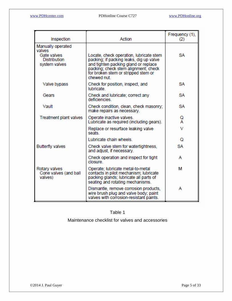
Table 1 (continued)
Maintenance checklist for valves and accessories

www.PDHcenter.com PDHonline Course C727 www.PDHonline.org
©2014 J. Paul Guyer Page 7 of 33
Table 1 (continued)
Maintenance checklist for valves and accessories

www.PDHcenter.com PDHonline Course C727 www.PDHonline.org
©2014 J. Paul Guyer Page 8 of 33
Table 1 (continued)
Maintenance checklist for valves and accessories

www.PDHcenter.com PDHonline Course C727 www.PDHonline.org
©2014 J. Paul Guyer Page 9 of 33
Table 1 (continued)
Maintenance checklist for valves and accessories
1.2.3.2 MAINTENANCE PROCEDURES. Distribution system valves are usually left
open and operated only during emergencies. To make sure that distribution valves
operate when needed, each valve in the system should be operated twice a year and
any indicated maintenance carried out. To check the operation of the valve, first close
the valve completely and then open it completely. Back off on the valve about one turn
to avoid locking the valve in an open position. If the valve does not operate properly,
perform necessary maintenance and repair at once.

www.PDHcenter.com PDHonline Course C727 www.PDHonline.org
©2014 J. Paul Guyer Page 10 of 33
1.2.3.2.1 VALVE SEATING. The usual cause for a valve not seating properly in the
closed position is foreign matter lodged on the valve seat. Open the valve slightly to
give a high-velocity flow across the valve seat. If necessary, open a hydrant to
increase flow enough to flush foreign matter from the valve seat.
1.2.3.2.2 VALVE-STEM SEALING
1.2.3.2.2.1 PACKING. Check and lubricate the valve-stem packing. Dry packing will
impede valve closure at all points of the stem movement. Lubricate dry packing by
pouring a mixture of half kerosene and half lubricating oil down a 1/2-inch (13-mm)
pipe to discharge the mixture onto the stem below the operating nut. If the packing
leaks, dig up the valve, tighten the packing gland, or replace the packing as
necessary. To reduce leakage while replacing packing, open the valve as wide as
possible.
1.2.3.2.2.2 O-RING SEALS. Most modern valves use O-ring seals rather than
packing. If water is leaking around the stem, replace the O-rings.
1.2.3.2.2.3 VALVE STEM. Valve stems may be out of alignment or broken, or may
have stripped threads. If the valve stem is out of alignment, the valve operates easily
near open or closed positions, but not when the valve is partially closed. A broken or
stripped stem permits unlimited turning of the stem without closing the valve. All of the
above conditions require replacing the valve stem. Follow the manufacturer’s
instructions for removing and inserting the stem. If the valve-stem nut is missing or
damaged, replace it.
1.2.3.2.2.4 VALVE SEAT REFACING. When a gate-valve seat leaks, remove the
valve and reface the valve seat. The procedure to follow should be detailed in the
manufacturer’s instructions and includes these general terms:
Remove the bonnet. Inspect and clean all working parts.

www.PDHcenter.com PDHonline Course C727 www.PDHonline.org
©2014 J. Paul Guyer Page 11 of 33
Check all working parts for signs of wear or deterioration.
Remove old packing or O-rings.
Refinish the working parts by grinding, sanding or polishing, and lapping.
Replace all parts beyond repair.
Replace the valve parts; repack and test the valve for proper operation.
1.3 HYDRANTS. Fire hydrants are mainly used for fire protection. Other uses include
flushing water mains and sewers, and filling tank trucks for street washing and tree
spraying. Hydrants may also be used as a temporary water source for construction
jobs. General information related to types of hydrants, component parts, O&M,
common operating problems, records, and hydrant safety is included herein.
1.3.1 HYDRANT O&M. Maintenance procedures for specific types of hydrants are
provided in Table 2. Additional details are provided below.
1.3.1.1 HYDRANT INSPECTION. Hydrants are inspected and tested by water utility
personnel accompanied by a fire department representative, according to command
and field engineering office directives. Hydrants can usually be maintained by
replacing all worn parts and seats through the top of the hydrant. The operator is
generally responsible for ensuring that the proper tools are used. Each year, test the
hydrant for tightness of joints and fittings in the following manner:
a) Remove one hydrant cap and replace it with a cap fitted with a
pressure gage. Open the valve slowly until it is wide open. Record the pressure.
b) Check for leakage at the following points:
Hydrant Top. If a leak is found, remove the cover plate and tighten or repack
the seal.
Nozzles Entering Barrel. For leaks here, caulk the connection with lead.
Nozzle Caps. If the nozzle caps are leaking, replace any defective gaskets.

www.PDHcenter.com PDHonline Course C727 www.PDHonline.org
©2014 J. Paul Guyer Page 12 of 33
Cracks in Barrel. For leaks from cracks in the barrel, install a new barrel or a
new hydrant.

www.PDHcenter.com PDHonline Course C727 www.PDHonline.org
©2014 J. Paul Guyer Page 13 of 33
Table 2
Maintenance checklist for fire hydrants
Drain Valve. Close this valve when the hydrant is open. If water comes out of
the drain or saturates the ground around the hydrant when the hydrant valve is
open, replace the drain valve facing or gasket.

www.PDHcenter.com PDHonline Course C727 www.PDHonline.org
©2014 J. Paul Guyer Page 14 of 33
c) Close the hydrant valve, open the second nozzle, open the hydrant valve, and flush
the hydrant. Record the pressure with the hydrant valve open.
d) Close the hydrant valve slowly and note the lowering of the water level in the
hydrant after the valve is closed. If the water level does not drop, the main valve is
leaking or the drain valve is plugged.
1.3.1.2 HYDRANT-FLOW TESTS. Conduct hydrant-flow testing in accordance with
the
latest edition of the applicable publications and requirements publications. During flow
tests, the hydrant nozzle needs to be unobstructed, so the only way of protecting
property is to choose the nozzle that will do the least damage. Provide barricades to
divert traffic and take any other precautions necessary to minimize property damage
and prevent personal injury.
1.3.1.3 HYDRANT FLUSHING. Water flow rates required for flushing water mains is
given herein. Before beginning the flushing, plan to divert flushing flow to prevent
property damage. Use flow diffusers or a length of fire hose where necessary to direct
the flow into a gutter or drainage ditch. A rigid pipe connected to a hydrant outlet and
turned at an angle to divert flow down a gutter is not considered a good idea. The
torque produced by the angular flow could be enough to twist or otherwise damage the
hydrant.
1.3.2 HYDRANT SAFETY. In addition to the general safety precautions detailed here,
special precautions must be taken to prevent injury and damage to private property
during hydrant flushing. Following are several special safety concerns:
Besides getting people wet, the force and volume of water from a full hydrant
stream are sufficient to seriously injure workers or pedestrians.
If traffic is not adequately controlled, drivers trying to avoid a hydrant stream
might stop quickly or swerve. An accident might result.

www.PDHcenter.com PDHonline Course C727 www.PDHonline.org
©2014 J. Paul Guyer Page 15 of 33
If the temperature is below freezing, water that is allowed to flow onto pavement
may freeze and cause accidents.
If flow is diverted with a hose to a sewer, care must be taken not to create a
cross-connection.
If flow is diverted with a hose, the end of the hose must be securely anchored.
A loose hose end can swing unpredictably and could cause serious injury.
www.PDHcenter.com PDHonline Course C727 www.PDHonline.org
©2014 J. Paul Guyer Page 16 of 33
2. INSTRUMENTATION AND CONTROLS (I&C), AND WATER METERS
2.1 SECTION. This section contains information on primary instrumentation (sensors),
secondary instrumentation (transmitters and recorders), and control systems as well
as supervisory control and data acquisition (SCADA) systems, which are relatively
new tools for controlling and monitoring water treatment systems. Special attention is
given to O&M of water meters and other flow measuring devices such as weirs and
flumes.
2.2 INSTRUMENTATION AND CONTROLS (I&C). The term “instrumentation,” as
used in the water works industry, refers to a very wide range of equipment used for
observation, measurement, and control. Equipment types range from simple,
mechanical, direct-reading meters and gages to complex electronic, automatic
monitoring/control systems. All I&C systems have some type of sensing device. More
complex systems will include one or more of the following elements: transmitter,
indicator, and recorder. Modern I&C equipment allows an operator to monitor and
control equipment, flow rates, pressures, levels, and processes not only at the water
treatment plant, but for all parts of the distribution network as well.
2.2.1 WATER METERS. The primary function of water meters is to measure and
record the volume of water flowing in a line. Flow is the most important measurement
made at water supply facilities. Flow data is used to account for the water treated and
pumped to distribution, chemical flow pacing, long-range planning, etc.
2.2.2 METER READING. Meters are generally furnished with registers that measure
water flow in terms of flow rate or total volume. Water meter registers are typically of
two general types: the straight-reading type and the circular-reading type. The
straight-reading type is read like the odometer on a car. The meter register reports the
number indicated by the counting wheels. Fixed zeroes to the right of the counting
wheel window should be included in the meter reading. The circular reading dial is
somewhat difficult to read and has been gradually replaced by straight registers on

www.PDHcenter.com PDHonline Course C727 www.PDHonline.org
©2014 J. Paul Guyer Page 17 of 33
new meters. When a hand on any scale is between two numbers of a circular reading
dial, the lower number is read. If the hand seems exactly on any figure, check the
hand on the next lower scale. If that hand is on the left side of zero, read the figure on
which the hand lies. Otherwise, read the next lower figure. Because the registers are
never reset while the meters are in service, the amounts recorded for any given period
are determined by subtraction. To obtain the volume of water that passed through the
meter since the previous reading, subtract the previously recorded reading from the
present reading. The maximum amount that can be indicated on the usual line meter
before it turns to all zeroes and starts over again is 99,999 cubic feet, or 999,999
gallons. Thus, to get a current measurement when the reading is lower than the last
previous one, add 100,000 to the present reading on a cubic feet meter, or 1,000,000
to the present reading on a gallon meter. The small denomination scale giving
fractions of 1 cubic foot or 10 gallons is used for testing purposes only and is
disregarded in the regular reading.
2.4 INSTRUMENT MAINTENANCE AND REPAIR. The success of water instrument
maintenance procedures is based on knowledge of the construction, operation, and
adjustment of the equipment; availability of the necessary special tools; and stored
spare parts and special instructions from manufacturers. For the special knowledge
necessary, maintenance personnel are advised to consult the manufacturer’s
instructions.
2.4.1 MAINTENANCE SCHEDULES. The design and intricacy of meters,
instrumentation, and automatic control systems depend on the function to be
performed and the manufacturer’s particular equipment. Because there are many
manufacturers of meters, instruments, and automatic controls, listing specific
maintenance procedures that apply to all units is not possible. The procedures here
are basic and the minimum required for the most common types of units. When
developing maintenance schedules, personnel may adapt the procedures given here
to specific directions issued by the manufacturers.

www.PDHcenter.com PDHonline Course C727 www.PDHonline.org
©2014 J. Paul Guyer Page 18 of 33
2.4.2 INSPECTION AND MAINTENANCE RECORDS. It is a good idea to keep a log
of all inspection and maintenance actions. A particularly useful record system is a card
file for each piece of equipment. This card shows the type of equipment, the
manufacturer’s serial number, the date installed, the location, and the frequency of
scheduled maintenance. If these cards are arranged chronologically, each card will
come to the attention of maintenance personnel at the proper time for the inspection to
be made. Many water suppliers are now using computers in their operation.
Information commonly kept on a service or meter history card is entered into a
computer to establish a permanent record. A control number is associated with each
service or meter. Any future information concerning work on a customer service line or
meter testing and repairs can be entered for the appropriate control number.
2.4.3 SENSOR MAINTENANCE. Maintenance procedures for flow, pressure and
level-sensing devices are given in Table 3.

www.PDHcenter.com PDHonline Course C727 www.PDHonline.org
©2014 J. Paul Guyer Page 19 of 33
Table 3
Maintenance checklist for flow, pressure and level sensors

www.PDHcenter.com PDHonline Course C727 www.PDHonline.org
©2014 J. Paul Guyer Page 20 of 33
Table 3 (continued)
Maintenance checklist for flow, pressure and level sensors
2.4.4 TRANSMISSION SYSTEM MAINTENANCE. Information needs to be
transmitted from the sensing device, which measures the variable, to the instruments
that indicate, record, or total it. The transmission system may be mechanical,
hydraulic, pneumatic, or electrical. Each system consists of two components—the
transmitter and the transmission link. Maintenance procedures for transmission
systems are summarized in Table 4.
2.4.5 INDICATOR, REGISTER, AND RECORDER MAINTENANCE. Besides
transmission devices, secondary instruments include indicators or gages (momentary

www.PDHcenter.com PDHonline Course C727 www.PDHonline.org
©2014 J. Paul Guyer Page 21 of 33
indication of discrete information), recorders (chart record of information by time), and
registers or totalizers (also termed “integrators”). The latter category expresses the
total quantity of measured variable from start to current time. There are many styles
and designs of each basic type, and various combinations of these types. Therefore,
no detailed maintenance procedure can cover all types, designs, and combinations.
Maintenance procedures depend not only on the type of receiver (indicator, recorder,
or register), but also on the type of transmission system used. It is recommended that
maintenance personnel study the manufacturer’s instructions for detailed procedures,
in addition to following the basic maintenance procedures for indicators, registers, and
recorders summarized in Table 5.
2.4.5.1 RECORDERS. Recording instruments have all of the fundamental elements of
an indicator unit and, in addition, contain a clock mechanism (spring or electrical), a
chart, and a marking pen. Charts may be either circular or strip and are changed on
schedule by operating personnel. Maintenance procedures depend on the type of
transmission system employed, as well as on the design and other factors. Consult the
manufacturer’s instructions for detailed procedures. General maintenance procedures
are included in Table 5.
2.4.5.2 TOTALIZERS OR REGISTERS. This type of receiver has internal components
similar to those in recorders. In addition, it contains an integrator mechanism that
converts transmitted signals into a sum of the total quantity of material that has moved
past the point of measurement from the beginning of the measured period to the time
of observation. This total appears on a numerical register similar to an automobile
odometer. Clean, service, and adjust registers according to the manufacturer’s
instructions on the same general schedule as recorders.

www.PDHcenter.com PDHonline Course C727 www.PDHonline.org
©2014 J. Paul Guyer Page 22 of 33
Table 4
Maintenance Checklist for Transmission Systems

www.PDHcenter.com PDHonline Course C727 www.PDHonline.org
©2014 J. Paul Guyer Page 23 of 33
Table 4
Maintenance Checklist for Transmission Systems

www.PDHcenter.com PDHonline Course C727 www.PDHonline.org
©2014 J. Paul Guyer Page 24 of 33
Table 5
Maintenance Checklist for Indicators, Registers, and Recorders

www.PDHcenter.com PDHonline Course C727 www.PDHonline.org
©2014 J. Paul Guyer Page 25 of 33
Table 5 (continued)
Maintenance Checklist for Indicators, Registers, and Recorders
2.4.5.3 COMBINATION TOTALIZER INDICATOR-RECORDER. There are various
combinations, designs, and styles of instruments in this classification. There are also
devices that sum totals from various individual totalizers, or show ratios of one flow to
another. In general, the maintenance procedures and schedules for this category are a
combination of the procedures for the individual units above. Develop a maintenance
schedule according to the manufacturer’s instructions.
2.4.6 WATER METER MAINTENANCE. Maintenance procedures for water meters
are summarized in Table 6.
2.4.7 WEIR AND FLUME MAINTENANCE. All types of head-area meters are used for
open-flow measurement, and their proper operation depends on the absence of any
kind of interference at the discharge opening. Maintenance procedures for weirs and
flumes are summarized in Table 7.
2.5 SAFETY. General hazards connected with servicing I&C systems include use of
hand tools, working in confined spaces, and electric shocks. Special attention should
be given to prevent electrical shock that may be caused by improper grounding of
building electrical systems onto the plumbing system. If residential water meters are

www.PDHcenter.com PDHonline Course C727 www.PDHonline.org
©2014 J. Paul Guyer Page 26 of 33
not mounted on a yoke, or if a permanent jumper wire is not provided across the meter
connections, use a separate wire with large alligator clips as a temporary bridge
between the pipes when meters are removed or installed.
Table 6
Maintenance Checklist for Water Meters

www.PDHcenter.com PDHonline Course C727 www.PDHonline.org
©2014 J. Paul Guyer Page 27 of 33
Table 7
Maintenance Checklist for Weirs and Flumes

www.PDHcenter.com PDHonline Course C727 www.PDHonline.org
©2014 J. Paul Guyer Page 28 of 33
3. CROSS-CONNECTION CONTROL AND BACKFLOW PREVENTION
3.1 CROSS-CONNECTIONS AND BACKFLOW. Cross-connections are the physical
links through which contaminated materials can enter a potable water supply. The
contaminant enters the potable water supply when the pressure of the polluted source
exceeds the pressure of the potable source. The flow of contaminated water to the
potable system is called “backflow.” Backflow of contaminated water through cross-
connections can occur in all water systems and does occur in most water systems.
Backflow results from either back pressure or back siphonage. Backflow due to back
pressure occurs when the user’s water system is under higher pressure than the
public water supply system. Back siphonage is caused by the development of negative
or sub-atmospheric pressures in the water supply piping. This condition occurs when
system pressure is lowered by pump malfunction or high fire flow.
3.2 CLASSES OF BACKFLOW HAZARDS. Backflow hazards have been divided into
the three classes—low, moderate, and high—as defined below.
3.2.1 CLASS I—LOW DEGREE OF HAZARD. If a backflow were to occur, the
resulting health significance would be limited to minor changes in the esthetic quality,
such as taste, odor, or color. The foreign substance must be nontoxic and nonbacterial
in nature, with no significant health effect.
3.2.2 CLASS II—MODERATE DEGREE OF HAZARD. If a backflow were to occur,
the esthetic qualities of the water supply would change significantly. The foreign
substance must be nontoxic to humans.
3.2.3 CLASS III—HIGH DEGREE OF HAZARD. If a backflow were to occur, the effect
on the water supply could cause illness or death if the water were consumed by
humans. The foreign substance may be toxic to humans either from a chemical,
bacteriological, or radiological standpoint. Effects of these contaminants may result
from short- or long-term exposure.

www.PDHcenter.com PDHonline Course C727 www.PDHonline.org
©2014 J. Paul Guyer Page 29 of 33
3.3 APPROVED BACKFLOW PREVENTION DEVICES. Devices that protect the
potable water supply from these backflow hazards are listed in Table 8 and discussed
below.
Table 8
Approved Backflow Devices
3.3.1 AIR GAP. An approved air gap may be used under any and all conditions of
hazard and pressure conditions.
3.3.2 VACUUM BREAKERS. Pressure and atmospheric vacuum breakers are
primarily in-plant or end-of-service line solutions to cross-connection. They are not
used in water service connections. They are placed at the end of a line, and at fixtures
or equipment that discharge to atmospheric pressure. These do not protect against
back pressure, only against back siphonage. Valves should not be located
downstream from an atmospheric type vacuum breaker. Note: Vacuum breakers are

www.PDHcenter.com PDHonline Course C727 www.PDHonline.org
©2014 J. Paul Guyer Page 30 of 33
permitted on irrigation systems regardless of hazard class for protection from back
siphonage only.
3.3.3 REDUCED PRESSURE PRINCIPLE DEVICE. The reduced pressure (RP)
principle device protects against both back pressure and back siphonage and can be
used for any degree of hazard.
3.3.4 DOUBLE CHECK VALVE ASSEMBLY. This device works in a back pressure or
back siphonage mode. This device neither discharges water nor provides a visual sign
of backflow or unit malfunction. Therefore, it does not offer the degree of protection
provided by the reduced pressure principle device.
3.4 SELECTION AND INSTALLATION OF BACKFLOW PREVENTERS. Selecting
proper devices is very important. However, having the proper device on the connection
is not sufficient; the device also needs to be installed correctly. Guidance on selecting
and installing backflow prevention devices is provided in par. 2.2.10. Critical potable
water supplies should have parallel installation of the proper approved backflow
prevention device. This avoids interruption to water service when maintenance or
testing is required. This type of installation also provides higher flow capacity than is
provided by one backflow preventer. Methods and devices occasionally promoted for
backflow prevention include the single check valve, the swivel connection, the
removable section or spool, and the barometric loop. None of these methods is
approved for use in many water systems. Reasons for their unacceptability are
discussed below:
A single check valve offers no visual or mechanical means of determining
malfunctioning. Since all such mechanical devices are subject to wear and
interference resulting from deposits and other factors, the single check valve is
not considered an adequate backflow preventer.
The swivel connection and removal section or spool are too easily allowed to
remain in place to be considered an acceptable means of backflow prevention.

www.PDHcenter.com PDHonline Course C727 www.PDHonline.org
©2014 J. Paul Guyer Page 31 of 33
A barometric loop consists of a vertical section of pipe, extending at least 35
feet (11 m) above the highest fixture. The principle is that a complete vacuum
cannot raise water to an elevation greater than 33.9 feet (10.3 m). The device
does not protect against backflow because of back pressure, and installing a
pipe loop of this height is usually costly and impractical.
3.5 INSPECTION AND TESTING SCHEDULE. Each installation should create a
schedule for inspecting and testing all backflow protection devices, including air gaps.
Determine the intervals between inspecting, testing, and overhauling each device
according to the age, condition of each device, and degree of hazard. It is important to
inspect all devices installed on Class III (high degree of hazard) cross-connections at
least once every 6 months (Table 33). In general, follow the overhaul intervals
recommended by the manufacturer. Ideally, overhaul intervals will not exceed 5 years.
Keep the inspection and testing schedule in the recurring work program.
Table 9
Suggested Intervals for Inspecting Backflow Devices
3.6.1 INSPECTION. A certified backflow inspector must inspect all cross-connections
and backflow prevention devices to ensure that:
An approval air gap is maintained.
Backflow prevention devices are in good condition.

www.PDHcenter.com PDHonline Course C727 www.PDHonline.org
©2014 J. Paul Guyer Page 32 of 33
New devices are properly installed and debris from the installation does not
interfere with functioning of the device. (This inspection is to be completed
within 1 week after acceptance and 3 months after installation.)
3.6.2 TESTING. Complete all testing according to the manufacturer's service
instructions. Repair and retest any device found to be defective until it is in satisfactory
condition.
3.7 MAINTENANCE OF BACKFLOW PREVENTERS. Maintenance is necessary for
any mechanical equipment to keep it operational. Therefore, it is generally best to
install any mechanical protective device in a location where it is accessible for routine
inspection, testing, and required maintenance. These devices are mechanical and
subject to breakdown, and they will need to be isolated during inspection and repair. If
there is only one service line from the potable system and if water service is required
100 percent of the time, a bypass and a second RP principle backflow preventer will
be required to provide an uninterrupted protected supply from the potable system.
3.8 RECORDS OF INSPECTION. Use an appropriate form approved to record data on
all cross-connections. Provide the location, degree of hazard, description of air gap or
protective device installed, and a sketch of the installation on the form. After each
inspection is completed, record the date of inspection, test results, observations,
corrective action taken, and name of the inspector on the appropriate form. For an air
gap, the test consists of a visual inspection, with “OK” recorded. Testing for other
backflow devices is more involved.
3.9 LOCATION RECORDS. In general, records of all cross-connection control or
backflow prevention devices should be prepared and properly maintained. These
records are to include an inventory listing of all locations and an individual record on
each location.

www.PDHcenter.com PDHonline Course C727 www.PDHonline.org
©2014 J. Paul Guyer Page 33 of 33
Table 9
Suggested Intervals for Inspecting Backflow Devices