Embed Size (px)
Citation preview

www.tjprc.org [email protected]
International Journal of Electrical and Electronics Engineering Research (IJEEER) ISSN(P): 2250-155X; ISSN(E): 2278-943X Vol. 4, Issue 4, Aug 2014, 55-72
© TJPRC Pvt. Ltd.
AN INVESTIGATION ON USE OF POWER SYSTEM STABILIZER ON TRANSIENT
STABILITY OF POWER SYSTEM
BHUWAN PRATAP SINGH1, M. P. SHARMA
2 & VISHU GUPTA
3
1M. Tech Student, Suresh Gyan Vihar University, Jaipur, Rajasthan, India
2AEN, RVPNL, Jaipur, Rajasthan, India
3Assistant Professor, Suresh Gyan Vihar University, Jaipur, Rajasthan, India
ABSTRACT
This paper describes the effect of Power System Stabilizers (PSS) on transient stability of power system after
occurrence of fault in power system. Studies have been carried out without and with PSS in AVR for a thermal power plant
having 8 nos. identical generating units. A dynamic model of the RajWest Lignite Thermal Power Plant situated in the
Western Rajasthan is adopted to simulate the effect of PSS for damping of po wer system oscillations. Simulation studies
indicate that AVR having supplementary control signal from PSS, transient stability of power system increase.
Power oscillations damp out faster. Frequency of generators reach in steady state condition in lesser time. With PSS,
maximum swing in power angle and power swing in transmission lines also reduce.
KEYWORDS: Power System Stabilizers , Thermal Power Plant, Raj West Lignite Thermal Power
INTRODUCTION
Power System Stabilizers (PSS) are the most well-known and efficient devices to damp the power system
oscillations caused by interruptions. The transient stability of a system can be improved by providing suitably tuned power
system stabilizers on selected generators to provide damping to critical oscillatory modes. Suitably tuned Power System
Stabilizers (PSS), will introduce a component of electrical torque in phase with generator rotor speed deviations resulting
in damping of low frequency power oscillations in which the generators are participating. The input to stabilizer signal may
be one of the locally available signals such as changes in rotor speed, rotor frequency, accelerating power, electrical power
output of generator or any other suitable signal. This stabilizing signal is compensated for phase and gain to result in
adequate component of electrical torque that results in damping of rotor oscillations and thereby enhance power
transmission and generation capabilities. Constantly increasing intricacy of electric power systems, has enhanced interests
in developing superior methodologies for Power System Stabilizers (PSS). Transient and dynamic stability considerations
are among the main issues in the reliable and efficient operation of power systems. Low Frequency Oscillation (LFO)
modes have been observed when power systems are interconnected by weak tie -lines. The LFO mode, with weak damping,
is also called the electromechanical oscillation mode, and it usually happens in the frequency range of 0.1 to 2 Hz.
PSSs are the most efficient devices for damp out these oscillations.
POWER SYSTEM DATA
8×135 MW Lignite based pit head Rajwest power plant is situated in Barmer District of Rajasthan. All units are
generating power at 13.8 kV voltage level. The two units are stepped up to 220 kV voltage level through 2x160 MVA,

56 Bhuwan Pratap Singh, M. P. Sharma & Vishu Gupta
Impact Factor (JCC): 5.9638 Index Copernicus Value (ICV): 3.0
13.8/220 kV generating transformers and the remaining six units are stepped up to 400 kV voltage level through 6 x 160
MVA, 13.8/400 kV generating transformers. Further 400 kV and 220 kV busses inside the plant are interconnected through
an ICT of 1×315 MVA, 400/220 kV. Then the power is evacuated to Jodhpur 400/220 kV, Barmer 400/220/132 kV,
and Dhaurimanna 220/132 kV grid substations through 220 kV and 400 kV transmission lines. The following are the major
interconnections with the Rajwest power plant to the Rajasthan grid
400kV Interconnections
400 kV S/C twin moose conductor line from Rajwest 400/220 kV substation to Barmer 400/220/132 kV
substation with a line length of 15.311 km.
400 kV D/C twin moose conductor line from Rajwest 400/220 kV substation to Jodhpur 400/220 kV substation
with a line length of 220 km.
1× 315 MVA, 400/220 kV Interconnecting transformer at Rajwest power plant.
220kV Interconnections
220 kV D/C zebra conductor line from Rajwest 400/220 kV substation to Barmer 400/220/132 kV substation with
a line length of 15.311 km.
220 kV S/C zebra conductor line from Rajwest 400/220 kV substation to Dhaurimanna 220/132 kV substation
with a line length of 90 km.
Figure 1 gives the interconnection diagram in the vicinity of the Raj West power plant
Figure 1: Interconnection Diagram in the Vicinity of the Raj West Power Plant
Network Reduction
In order to study the local modes of oscillations where the Rajwest power plant generators oscillates with the rest
of the Rajasthan system, it is sufficient to reduce the network at the boundary busses i.e. Barmer 220 kV and 400kV,

An Investigation on Use of Power System Stabilizer on Transient Stability of Power System 57
www.tjprc.org [email protected]
Dhaurimanna 220 kV and Jodhpur 400 kV with the dynamic equivalents. In the process of network reduction,
some fictitious transformers are also added at the boundary busses based on the fault levels at the boundary buses.
Three Phase Fault Levels at Boundary Buses
To arrive at the equivalent impedance at the boundary buses, three phases to ground fault is created at the
boundary busses with the full system and the contribution from the other braches which are of no interest (not represented
in reduced network) and to be represented in the equivalents are calculated and represented in the equivalent system.
Table 1 shows the three phases to ground fault contribution from all branches connected to the specified buses.
Table 1: 3-Φ Fault Current at the Boundary Buses
S. No. Fault at Bus
3-Phase Fault
with Reduced
System in kA
3-Phase Fault
with Full
System in kA
1 Barmer 220 kV 18.893 17.854
2 Dhaurimanna
220 kV 8.722 8.462
3 Jodhpur 400 kV 14.216 13.433
4 Barmer 400 kV 12.163 11.096
Single line diagram of power system network with load flow study results is placed in figure 2.
Figure 2: Single Line Diagram of Power System for Simulation
Transmission Line Parameters
Based on data available on transmission design followed by RRVPNL, per kilometer line parameters are given in
Table 2

58 Bhuwan Pratap Singh, M. P. Sharma & Vishu Gupta
Impact Factor (JCC): 5.9638 Index Copernicus Value (ICV): 3.0
Table 2: Transmission Line Parameters
S. No Description Conductor Type
Conductor Type Twin Moose Zebra Panther
1 Voltage Rating 400 220 132
2 Positive sequence resistance in ohm/km/ckt 0.029792 0.0748746 0.1622174
3 Positive sequence reactance in ohm/km/ckt 0.332 0.3992516 0.3861158
4 Positive sequence half line charging
susceptance in mho/km/ckt (B/2)
1.734375 e-006 1.466942 e-006 1.46349 e-006
5 Zero sequence resistance in ohm/km/ckt 0.16192 0.219976 0.4056307
6 Zero sequence reactance in ohm/km/ckt 1.24 1.339228 1.6221744
7 Zero sequence half line charging
susceptance in mho/km/ckt (B/2)
1.12e-006 9.20041e-007 1.317141e-007
Generator Parameters
There are total 8 units of 135 MW rating at the Rajwest power plant. Generator parameters are same for all
generators. Generator parameter are given in Table 3.
Table 3: Generator Parameters
S. No Parameter Description Value
1 MW rating 135
2 MVA rating 158.8
3 No. of units 8
4 Rated voltage in kV 13.8
5 Rated power factor 0.85 (Lag)
6 Armature Resistance (Ra) in pu (Stator Resistance per phase at 75 C) 1.02565e-3
7 Negative Sequence Reactance (Unsaturated) 0.19 pu
8 Potier Reactance 0.24 pu
9 Zero Sequence Reactance (Unsaturated) 0.19 pu
10 Direct Axis Reactance (Xd) (unsaturated) 2.21 pu
11 Direct Axis Transient Reactance (Xd') (Unsaturated) 0.24 pu
12 Direct Axis Sub- Transient Reactance (Xd") (Unsaturated) 0.18 pu
13 Quadrature Axis Reactance (Xq) (unsaturated) 2.072 pu
14 Quadrature Axis Transient Reactance (Xq') (Unsaturated) 0.391 pu
15 Direct Axis Sub- Transient Reactance (Xq") (Unsaturated) 0.195 pu
16 Direct Axis Transient Open Circuit Time Constant (T‟do) (Unsaturated) 9.34 s
17 Direct Axis Sub – Transient Open Circuit Time Constant (T”do) (Unsaturated) 0.017 s
18 Quadrature Axis Transient Open Circuit Time Constant (T‟qo) (Unsaturated) 0.904 s
19 Quadrature Axis Sub – Transient Open Circuit Time Constant (T”qo) (Unsaturated) 0.034 s
20 Generator Inertia Constant H (Generator +turbine + governor +excitation system) in
MJ/MVA 2.51
21 NGT Voltage rating 13.8/.240
kV
22 NGR 0.46 ohms
Generator Transformer Details
Raj west Power Plant two units are stepped up to 220 kV level through 13.8/220 kV generating transformers and
the remaining units are stepped up to 400 kV level through 13.8/400 kV generating transformers. The 13.8/220 kV and
13.8/400 kV generator transformer details is given in Table 4.

An Investigation on Use of Power System Stabilizer on Transient Stability of Power System 59
www.tjprc.org [email protected]
Table 4: Details of 13.8/220 kV and 13.8/400 kV Generating Transformer
Parameters Specification Specification
Transformer Name
Generator
Transformer (13.8
kV/230 kV)
Generator Transformer
(13.8 kV/ 420 kV)
MVA Rating 160 160
Primary Voltage in kV 13.8 13.8
Secondary Voltage in kV 230 230
% Positive sequence Impedance 12.5 12.5
% Zero sequence Impedance 11.25 11.25
Winding Configuration Delta / Star
grounded Delta / Star grounded
Type of tap changer (On load or Off load) Off Load tap
changer Off Load tap changer
Tap
Position
Total no of taps 5 5
Nominal tap 3 3
Set tap 3 2
Minimum & Maximum Tap range in pu
(or) % •±5% •±5%
Tap
Voltage
Minimum voltage in kV 218.5 399
Maximum voltage in kV 241.5 441
Exciter System Details
The main function of AVR is to automatically adjust the field current of the sy nchronous generator to maintain
the terminal voltage within continuous capability of the generator. All the generating units have the identical excitation
systems i.e. AC excitation system (Field controlled alternator rectifier excitation system). The rect ifier in this excitation
system is stationary and is fed from the generator terminal. The voltage regulator controls the firing angles of the thyristo rs
and converts AC in to appropriate DC. This DC supply is fed to field winding of the alternator through slip rings.
The block diagram of the excitation system in the figure 3.
Figure 3: Block Diagram of Excitation System
The Excitation system parameters are same for all units i.e. the generators which are stepped up to 220 kV voltage
level as well as the generators stepped up to 400 kV voltage level. Excitation parameters are given in table 5.
Table 5: Excitation System Parameters
Constant Name Parameter Value
KA Exciter Gain 25
TR Amplifier time constant in s 0.02
TA Integral Time Constant 8.335
TS Gate Control Unit and
Converter Time Constant 0.005
Uk max Maximum voltage in pu 7.42
Uk min Minimum voltage in pu -5.7

60 Bhuwan Pratap Singh, M. P. Sharma & Vishu Gupta
Impact Factor (JCC): 5.9638 Index Copernicus Value (ICV): 3.0
Power System Stabilizer (PSS)
High performance excitation systems are essential for maintaining steady state and transient stability of modern
synchronous generators, apart from providing fast control of the terminal voltage. But the fast acting exciters with high
AVR gain can contribute to oscillatory instability in the power systems. This type of instability is characterized by low
frequency (0.1 to 3 Hz) power oscillations which can persist (or even grow in magnitude) for no apparent reasons.
This type of instability can endanger system security and limit power transfer. The major factors that contrib ute to the
instability are
Loading of the generator or Tie line
Power transfer capability of transmission lines
Power factor of the generators (Leading power factor operation is more problematic than the lagging power
factor)
AVR gain
A cost effective and satisfactory solution to the problem of oscillatory instability is to provide damping for
generator rotor oscillations. This is conveniently done by providing Power System Stabilizers (PSS) which are
supplementary controllers in the excitation systems. This supplementary signal is derived from rotor velocity, frequency,
electrical power or combination of these variables.
PSS Block Diagram
The block diagram of PSS used in the Rajwest power plant is shown in Figure 4. All the units in power plant have
the same type of PSS.
Figure 4: PSS Block Diagram
The input to the PSS is electrical power (active) which is derived from the terminal of the generator.
Each synchronous generator has the same input arrangement and the output of the PSS will act as a supplementary signal
to AVR as shown in Figure 5. The PSS block diagram consists of Wash out circuit, dynamic lead lag compensators, and a
limiter to limit the absolute value of PSS output.

An Investigation on Use of Power System Stabilizer on Transient Stability of Power System 61
www.tjprc.org [email protected]
Figure 5: AVR with PSS Block Diagram
Washout Circuit
The washout circuit is provided to eliminate steady state bias in the output of PSS which will modify the generator
terminal voltage. The PSS is expected to respond only to transient variations in the input signal and not to the DC offsets in
the signal. The washout circuit acts essentially as a high pass filter and it must pass all frequencies that are of interest.
Dynamic Compensator
The dynamic compensator consists of lead lag (phase) compensator blocks. The phase compensation block
provides the appropriate phase lead characteristic to compensate for the phase lag between exciter input and the generator
electrical (air-gap) torque. The dynamic compensator as shown in Figure 4 has two lead lag stages and has the following
transfer function.
There are two design criteria for the lead lag circuit namely,
The time constants, T1 to T4 in the above equation are to be chosen from the requirements of the phase
compensation to achieve desired damping torque.
The gain of the PSS is to be chosen to provide adequate damping of all critical modes under various operating
conditions. It is to be noted that PSS is tuned at a particular operating condition (full load condition with strong or
weak AC system) which is most critical. Although PSS may be tuned to give optimum damping under such
condition, the performance will not be optimal under other conditions.
Limiter
The output of the PSS must be limited to prevent the PSS acting to counter the action of the AVR. For example,
when load rejection takes place, the AVR acts to reduce the terminal voltage when PSS action calls for higher value of the
terminal voltage. It may be desirable to trip the PSS in case of load rejection. The negative limit of PSS output is of
importance during back swing of the rotor (after initial acceleration is over). The AVR action is required to maintain the
voltage (and thus prevent loss of synchronism) after the angular separation has increased. The PSS action in the negative
direction must be curtailed more than in the positive direction. For this purpose, the PSS available at the Rajwest Power

62 Bhuwan Pratap Singh, M. P. Sharma & Vishu Gupta
Impact Factor (JCC): 5.9638 Index Copernicus Value (ICV): 3.0
plant has the following setting limits and is same for all the generating units. The parameters for the PSS and its settable
range with actual settings are tabulated in Table 6.
Table 6: PSS Parameter Settings Range
Parameter Description Unit Range Actual Settings
T1 Filter Time constant s 0.003~0.02 0.01
TW1 Washout Time Constant s 0.01~15 5
Ks1 PSS Gain Factor pu 0.1~100 -30
TL1 Time constant of conditioning network s 0.01~10 0.02
TL2 Time constant of conditioning network s 0.01~10 0.01
TL3 Time constant of conditioning network s 0.01~10 0.02
TL4 Time constant of conditioning network s 0.01~10 0.01
Usmax Upper limit of stabilizing Value pu 100% +1.0
Usmin Lower limit of stabilizing Value pu 100% 1.0
Governor Parameters
The block diagrams of governor-turbine model for 8x135 MW machines are as shown in Figure 6 and Figure 7
respectively. The time constants associated with governor and turbine system are shown in Table 7.
Figure 6: Block Diagram of Governor Model for 135 MW Generator
Figure 7: Block Diagram of Turbine Model for 135 MW Generator
Table 7: Steam Turbine Data for 135 MW Generator
S. No Constant Description Value
1 Droop Droop 0.05
2 T1 T1 in seconds 0.3
3 T2 Servo motor time constant in s 2
4 K1 Power extraction at HP turbine 0.3
5 K2 Power extraction at IP turbine 0.397
6 K3 Power extraction at LP turbine 0.303
7 Thp HP section time constant in second 0.1
8 Tip IP section time constant in second 10.12
9 Tlp LP section time constant in second 0.14
10 Pmax Maximum power limit in pu 1.1
11 Pmin Minimum power limit in pu 0.01

An Investigation on Use of Power System Stabilizer on Transient Stability of Power System 63
www.tjprc.org [email protected]
SIMULATION RESULTS
Faults of varying severity are simulated and stability of RWPL generators is investigated without and with PSS.
Plots of following parameters are analyzed:-
Electrical power output of generators
Swing curve of generators
Frequency variation of generators
The terminal voltage of generators
The field voltage in pu
The power flow on 220 kV D/C Rajwest-Jodhpur line
The power flow on 400 kV D/C Rajwest-Jodhpur line
Case 1: Single line to ground fault at Rajwest 220 kV bus created at 1.0 sec and cleared at 1.16 sec
Plots for foresaid disturbance are placed from figure 8 to figure 14.
Figure 8: Electric Power Variation of Generators (G1 + G2) without and with PSS
Figure 9: Swing Curve of Generators (G1 + G2) without and with PSS
64 Bhuwan Pratap Singh, M. P. Sharma & Vishu Gupta
Impact Factor (JCC): 5.9638 Index Copernicus Value (ICV): 3.0
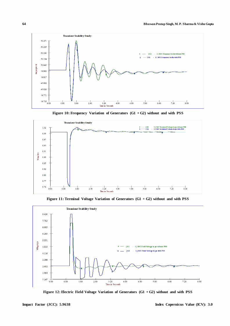
Figure 10: Frequency Variation of Generators (G1 + G2) without and with PSS
Figure 11: Terminal Voltage Variation of Generators (G1 + G2) without and with PSS
Figure 12: Electric Field Voltage Variation of Generators (G1 + G2) without and with PSS
An Investigation on Use of Power System Stabilizer on Transient Stability of Power System 65
www.tjprc.org [email protected]
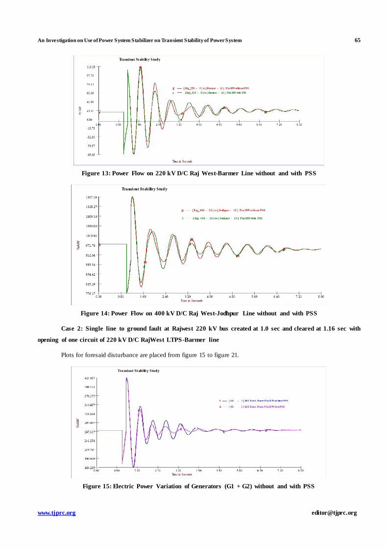
Figure 13: Power Flow on 220 kV D/C Raj West-Barmer Line without and with PSS
Figure 14: Power Flow on 400 kV D/C Raj West-Jodhpur Line without and with PSS
Case 2: Single line to ground fault at Rajwest 220 kV bus created at 1.0 sec and cleared at 1.16 sec with
opening of one circuit of 220 kV D/C RajWest LTPS-Barmer line
Plots for foresaid disturbance are placed from figure 15 to figure 21.
Figure 15: Electric Power Variation of Generators (G1 + G2) without and with PSS

66 Bhuwan Pratap Singh, M. P. Sharma & Vishu Gupta
Impact Factor (JCC): 5.9638 Index Copernicus Value (ICV): 3.0
Figure 16: Swing Curve of Generators (G1 + G2) without and with PSS
Figure 17: Frequency Variation of Generators (G1 + G2) without and with PSS
Figure 18: Terminal Voltage Variation of Generators (G1 + G2) without and with PSS
An Investigation on Use of Power System Stabilizer on Transient Stability of Power System 67
www.tjprc.org [email protected]
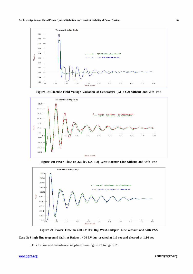
Figure 19: Electric Field Voltage Variation of Generators (G1 + G2) without and with PSS
Figure 20: Power Flow on 220 kV D/C Raj West-Barmer Line without and with PSS
Figure 21: Power Flow on 400 kV D/C Raj West-Jodhpur Line without and with PSS
Case 3: Single line to ground fault at Rajwest 400 kV bus created at 1.0 sec and cleared at 1.16 sec
Plots for foresaid disturbance are placed from figure 22 to figure 28.

68 Bhuwan Pratap Singh, M. P. Sharma & Vishu Gupta
Impact Factor (JCC): 5.9638 Index Copernicus Value (ICV): 3.0
Figure 22: Electric Power Output Variation of Generators (G3 to G6) without and with PSS
Figure 23: Swing Curve of Generators (G3 to G6) without and with PSS
Figure 24: Frequency Variation of Generators (G3 to G6) without and with PSS

An Investigation on Use of Power System Stabilizer on Transient Stability of Power System 69
www.tjprc.org [email protected]
Figure 25: Terminal Voltage Variation of Generators (G3 to G6) without and with PSS
Figure 26: Electric Field Voltage Variation of Generators (G3 to G6) without and with PSS
Figure 27: Power Flow on 220 kV D/C Raj West-Barmer Line without and with PSS

70 Bhuwan Pratap Singh, M. P. Sharma & Vishu Gupta
Impact Factor (JCC): 5.9638 Index Copernicus Value (ICV): 3.0
Figure 28: Power Flow on 400 kV D/C Raj West-Jodhpur Line without and with PSS
OBSERVATIONS
With PSS, initial peak in the electrical power output is slightly more than without PSS due to the fact that under
faulty condition, the voltage is reduced and at the same time active power output also reduces. Since the AVR and
PSS action under this condition is to increase the power output of the generator. This is due to the peculiar design
of the AVR-PSS module where in the output signal of the PSS is added at the field voltage rather than at th e
generator reference voltage. But it is also noted that, the oscillations in the electrical power output subsequent to
the first peak are better damped. The oscillations in the electrical power are damped in lesser time with PSS as
compared to without PSS.
Swing curves indicate that with PSS, maximum oscillation in power angle of generators are reduce in first as well
as subsequent swings. The oscillations in the generators power angle are damped in lesser time with PSS as
compared to without PSS.
Frequency curves indicate that oscillations in the generators frequency is reduce in first as well as subsequent
swings. The oscillations in the generators frequency are damped in faster with PSS.
With PSS, generator field voltage is increase due to addition of PSS output in the AVR output so that oscillations
in the generator speed are damped out.
With PSS, there is a lesser reduction in generators terminal voltage as compared to without PSS.
With PSS, Power oscillations in transmission lines are less as compared to without PSS.
CONCLUSIONS
In this paper simulation studies have been carried out for a thermal power plant having 8 nos. identical units for
different types of faults to find out the effect of power system stabilizers on transient stability of power system. Studies
have been performed without and with PSS for different types of faults in the power system. Simulation studies indicate
that AVR having supplementary control signal from PSS, transient stability of power system increase. Power oscillations
damp out faster. Frequency of generators reach in steady state condition in lesser time. With PSS, maximum swing in
power angle and power swing in transmission lines are also reduce.

An Investigation on Use of Power System Stabilizer on Transient Stability of Power System 71
www.tjprc.org [email protected]
REFERENCES
1. K. R. Padiyar, „Power system dynamics, stability & control‟, (Book), BS Publications, 2006.
2. Prabha Kundur, „Power system stability & control‟, (Book), Tata McGraw Hill, 2007.
3. E. V. Larsen, P. Swann, „Applying Power system stabilizers, Part I, II and III‟, IEEE Transactions on Power
Apparatus & systems, Vol. PAS 100, No.6, pp 3017-3046, June 1981.
4. Y. Hsu, S. Shyue, C. Su, “Low frequency oscillations in longitudinal systems: experience with dynamic stability
of Taiwan power system”, IEEE Trans., Vol. PWRS-2, No. 1, February 1987, pp. 92-100.
5. B. E. Elliason, D. J. Hill, “Damping structure and sensitivity in the NORDEL power system”, IEEE Trans. on
Power Systems, Vol. 7, NO. 1, 1992, pp. 97-105.
6. Chung-Liang Chang, Chuan-Sheng Liu, Chun-Kuang KO, Experience with power system stabilizers in a
longitudinal power system”, IEEE Trans. on Power Systems, Vol. 10, No. 1, February 1995. pp. 539-545.
7. F. Aboytes, G. Arroyo, “Application of static VAR compensators in longitudinal power systems”, IEEE Trans.
On Power Apparatus and Systems, Vol. PAS-102, No. 10, October, 1983, pp. 3460-3466
8. F. P. deMello and C. Concordia, "Concepts of Spmnous Machine Stability as Affected by Excitation Control".
IEEE Transadions on Power Apparatus and Systems, Vol. PAS88-4, April 19. pp 316-330.
9. P. L. Dandeno. A. N. Karas. K. R. McClymont and W. Watson. "Effect of High-speed Rectifier Excitation
Systems on Generator Stability Limits". IEEE Transactions on Power Apparatus and Systems, Vol. PAS87-1.
January 1 9 6 8, pp 190-201
10. W. Watson and G. Manchur. "Experience with Supplementary Damping Signals fo r Generator Static Excitation
Systems". IEEE Transactions on Power Apparatus & Systems, Vol. PAW-1, Jan/Feb. 1973, pp 199-204.
AUTHOR’S DETAILS
Mr. Bhuwan Pratap Singh has received his B. Tech degree in Electrical Engineering from Rajasthan Technical
University, Kota in 2011. He is currently pursuing M. Tech.(Power System) from Suresh Gyan Vihar University,
Jaipur (email: [email protected])
Dr. M. P. Sharma received the B. E. degree in Electrical Engineering in 1996 Govt. Engineering College, Kota,
Rajasthan and M. E. degree in Power Systems in 2001 and Ph. D. degree in 2009 from Malaviya Regional

72 Bhuwan Pratap Singh, M. P. Sharma & Vishu Gupta
Impact Factor (JCC): 5.9638 Index Copernicus Value (ICV): 3.0
Engineering College, Jaipur (Now name as MNIT). He is presently working as Assistant Engineer, Rajasthan
Rajya Vidhyut Prasaran Nigam Ltd., Jaipur. He is involved in the system studies of Rajasthan power system for
development of power transmission system in Rajasthan and planning of the power evacuation system for new
power plants. His research interest includes Reactive Power Optimization, Power System Stability, Islanding of
power system, reduction of T&D losses and protection of power system.(email:[email protected])
Ms Vishu Gupta has finished her bachelor of science in Electrical Engineering(B. S. S.E) in 2009 and Master of
Science in Electrical Engineering(M. S. E. E.) in 2012 from the University of Idaho, Mascow, Idaho, USA. She is
currently working in Suresh Gyan Vihar University, Jaipur, India as an Assistant Professor in the department of
Electrical Engineering. Research interest includes low power consumption in power electronics devices,
embedded system application in power system and power electronics.