Embed Size (px)
Citation preview
University of Manchester
School of Computer Science
MSc in Computer Security
An iPhone Application forProviding iBeacon-based Services
to StudentsProgress Report
Author:Mohammed Binsabbar
Supervisor:Dr. Ning Zhang
May 9, 2014
Abstract
iBeacon is an extension to the location service offered by Apple inits devices. It allows iPhone applications to become location-aware.iBeacon is based on Bluetooth Low Energy (BLE) and provides aproximity location service for an indoor environment. Nowadays,mobile phones are equipped with advance technologies. One ofthese technologies is BLE. BLE consumes less energy from the de-vice, hence, making it a good candidate to use for indoor positioningsystem.
Mobile phones can be used to enhance student’s services. One ofthese services is taking the attendance. Taking attendance requiresa location factor of the student. Hence, iBeacon can be used for thispurpose.
The project is going to implement iBeacon-bases services for stu-dents. This includes implementing two applications. A backendserver, which has the location information in its database, and it of-fers the services. An iPhone application which uses iBeacon signalsto request services from the server. This report outlines the currentprogress in the project.
1
List of Figures
1 Estimote Beacons . . . . . . . . . . . . . . . . . . . . . . . . . 202 The system architecture . . . . . . . . . . . . . . . . . . . . . 233 Summary of requesting a ServicePass protocol. . . . . . . . 284 Summary of requesting a service protocol. . . . . . . . . . . 295 The iPhone application flowchart for logging in . . . . . . . 336 Screenshots of the current UI for the iPhone implementation 347 Project Plan . . . . . . . . . . . . . . . . . . . . . . . . . . . . 36
List of Tables
1 iBeacon signal address components. . . . . . . . . . . . . . . 112 Abbreviations used in the protocol description. . . . . . . . 25
2
Contents
1 Introduction 51.1 Project Aims and Goals . . . . . . . . . . . . . . . . . . . . . 51.2 Report Outline . . . . . . . . . . . . . . . . . . . . . . . . . . . 6
2 Background Research 72.1 An Overview of Navigation System Services . . . . . . . . . 7
2.1.1 Global Navigation Satellite System (GNSS) . . . . . . 72.1.2 Indoor Positioning System (IPS) . . . . . . . . . . . . 82.1.3 Technologies Used for Indoor Positioning System . . 92.1.4 Bluetooth Low Energy and iBeacon . . . . . . . . . . 11
2.2 An Overview of Attendance Tracking . . . . . . . . . . . . . 122.3 Password-Based User Authentication . . . . . . . . . . . . . 132.4 iBeacon-based Student Services with Authentication Capa-
bility . . . . . . . . . . . . . . . . . . . . . . . . . . . . . . . . 152.4.1 The Origin of the Project Idea . . . . . . . . . . . . . . 152.4.2 The Requirements for Taking Attendance . . . . . . . 15
3 Research Methods 163.1 Software Development Methodology . . . . . . . . . . . . . . 16
3.1.1 Iterative and Incremental Approach . . . . . . . . . . 163.1.2 Evolutionary Prototyping . . . . . . . . . . . . . . . . 163.1.3 Iteration Length and Goals . . . . . . . . . . . . . . . 17
3.2 Defining the System Requirements . . . . . . . . . . . . . . . 173.3 Software Design Pattern . . . . . . . . . . . . . . . . . . . . . 183.4 Out of Scope Issues . . . . . . . . . . . . . . . . . . . . . . . . 193.5 Selection of Tools . . . . . . . . . . . . . . . . . . . . . . . . . 19
3.5.1 iBeacon Emitter . . . . . . . . . . . . . . . . . . . . . . 193.5.2 Server Hosting . . . . . . . . . . . . . . . . . . . . . . 193.5.3 Application Development Environment . . . . . . . . 20
3.6 System Evaluation . . . . . . . . . . . . . . . . . . . . . . . . 21
4 Project Progress 224.1 Current System Requirements . . . . . . . . . . . . . . . . . . 224.2 Designing Login Protocol . . . . . . . . . . . . . . . . . . . . 22
4.2.1 Security Requirements . . . . . . . . . . . . . . . . . . 234.2.2 Assumptions . . . . . . . . . . . . . . . . . . . . . . . 24
3
4.3 The Login Protocol . . . . . . . . . . . . . . . . . . . . . . . . 244.3.1 Abbreviations . . . . . . . . . . . . . . . . . . . . . . . 254.3.2 Requesting a ServicePass . . . . . . . . . . . . . . . . . 264.3.3 Requesting Service . . . . . . . . . . . . . . . . . . . . 27
4.4 Security Analysis of the Protocol . . . . . . . . . . . . . . . . 294.5 Selection of Hashing Algorithms . . . . . . . . . . . . . . . . 314.6 Current Implementation . . . . . . . . . . . . . . . . . . . . . 32
4.6.1 The Server Application . . . . . . . . . . . . . . . . . 324.6.2 The iPhone Application . . . . . . . . . . . . . . . . . 32
5 Conclusion and Future Work 35
4
1 Introduction
Since the introduction of the first consumer mobile phone in 1980s by Mo-torola, there have been continuos developments in the technology used tomake mobile phones [24]. Thanks to these developments, nowadays, mo-bile phones are built using very advance technologies. For example, theyare equipped with fast CPUs, large RAMs and different wireless tech-nologies. As a result, mobile phones have become capable of performingcomplex tasks. In the past, these tasks would require conventional com-puters.
This advance progress in mobile phones have attracted more con-sumers. Based on figures by Gartner Inc, the number of mobile phoneowners are growing [26]. This increase in mobile phone sales has creatednew usage for mobile phones, which helps in increasing the person’sproductivity. There is a wide range of mobile applications for increasingproductivity. These applications range from role-specific applications togeneral-purpose applications. For example, timetable and assignment or-ganiser designed specifically for students, and "To Do" applications forgeneral purpose and day to day use.
A context-aware application is an application which can adjust its be-haviour and functionality based on the context inputs around it. Forexample, in a location-aware application, the application can offer certainservices to the user based on the user’s current location. iBeacon is anextension to the location service offered by Apple iOS devices. It allowsiOS application to become aware of its location in an indoor environmentvia iBeacon signals. iBeacon is a bluetooth low energy payload, whichcarries location information related to its beacon. iOS applications canmake use of iBeacon to create new experience for the users. [17]
Given the advance in mobile phone technology and the availability ofiBeacon facility, it possible to enhance and improve some student services.For example, iBeacon-enabled mobile application can be developed toautomatically take the student’s attendance.
1.1 Project Aims and Goals
The aim of the project is to explore the potential use of iBeacon facilityas an indoor positioning system in Kilburn building to provide student
5
services. The project aims at:
1. Investigating the advantages of using iBeacon to provide location-based services in an indoor environment.
2. Investigating what student services can be improved by using iBea-con.
3. Proposing a set of enhancements for those student services, that canbe improved.
4. Proposing some new student services, which can take advantage ofthe IPS.
5. Investigating the limitations and difficulties of using iBeacon.
The goal of the project is to design and implement iBeacon-based in-door positioning system in Kilburn building using Estimote [4] beacons.The project is going to design and implement the backend server applica-tion, which offers the location-based services to its client. Moreover, theproject will produce an iPhone application (student’s client) that makesuse the indoor positioning systems in Kilburn building to request servicesfrom the server. Lastly, the project will design and implement a login pro-tocol, which makes using the client application secure and convenient forthe student.
1.2 Report Outline
In section 2, a background research about old and current positioning sys-tems for outdoor and indoor environments is discussed. This is followedby a brief background discussion about technologies, which have beenused to track student’s attendance. Then, password-based client authen-tication is described. Section 3 describes how the project will be carriedout. It talks about the software development approach. The section in-cludes a description of the system evaluation. Section 4 shows the currentprogress of the project. It focuses on the design and implementation ofthe login protocol. It also includes a brief discussion of the current serverapplication and iPhone application implementations. Finally, the reportis concluded.
6
2 Background Research
2.1 An Overview of Navigation System Services
As stated in ‘Global Positioning Systems, Inertial Navigation, and Inte-gration’ book [32], “there are five different forms of navigation”. Theseforms are; Pilotage, Dead Reckoning, Celestial Navigation, Radio Navi-gation, and Inertial Navigation. The Radio Navigation, which the projectis related to, makes use of radio signals in order to provide location ser-vice. For an outdoor environment, the Global Positioning System (GPS)has been widely used for civilian purpose since the 1980s. Before the1980s, GPS had a restricted use, and used mainly for military purposes.There have been some attempts to provide indoor positioning systemsthat make use of radio frequencies, such as bluetooth and wireless. [36]
2.1.1 Global Navigation Satellite System (GNSS)
GNSSs depend mainly on satellite signals. Currently, there are two GNSSsin use. The first one is the Global Positioning System (GPS), which wasdeveloped by U.S Department of Defence. There are about 28 satellitesoperating in an orbit around the earth. They transmit signals, which carryhelpful information, to a receiver device on the earth in order to enablethe receiver to locate itself. Global Orbiting Navigation Satellite System(GLONASS) is another GNSS. It uses different configuration from the oneused in the GPS. It was developed by the Soviet Union, currently RussianRepublic. [32]
Two more GNSSs are in developments now. Galileo is a new satel-lite based-navigation system, which is being developed by the EuropeanCommission’s Galileo Single Task Force. One of Galileo project goals isto provide more accurate and precise position than GPS [32]. Galileo isexpected to be fully operational in 2019 [18]. China as well is developinga Compass Global Navigation System (CGVS), which is an expansion ofthe BeiDou Navigation Satellite System. BeiDou has limited operationsand coverage. The CGVS is expected to be deployed in 2020 [15].
Originally the GPS was designed for military purpose only. Later, ithas become available for other services for civilian use. Nowadays, GPShas many different applications, which range from providing precise timesynchronisation to enabling navigation in an open environment [16] [14].
7
Google Maps application for mobile phones is one example of using GPSfor navigation.
There are some technical issues with the use of GNSS, which could beresulted from inaccurate calculations by the receiving device. These havebeen addressed by upgrading the used equipments and improving thealgorithms. Despite these technical issues, there are non-technical limita-tions as well. In general, in places where satellite signals are obstructed,like in an underground or an indoor environment, the use of GNSS be-comes useless. Hence, some recent efforts have been made to provide anindoor positioning system. [27]
2.1.2 Indoor Positioning System (IPS)
An indoor positioning system is a system, which implements the neces-sary infrastructure in order to provide indoor location services to enableobjects to be located in an indoor environment. The system uses differenttechnology from the ones used in GNSS to determine an object’s location.However, there are some similarities in the way a location is calculated.Currently, there is no standardisation for the technology used in IPSs, andmany various techniques and solutions have been proposed. [39]
The purpose of the IPS is to provide location service in places, wheresatellite signals are partially or completely blocked, especially inside build-ings. The complexity of the indoor environment structure affects thetransmission of the satellite signals, hence, resulting in multi-path ef-fects [35] [39]. For example, the GPS can detect that an object is in abuilding, however, it cannot determine where exactly in the building.Google maps uses public wireless signals installed in malls to provideindoor navigations, like it did in the Mall of America, in Bloomington,Minnesota [36].
IPS has various applications, which include navigation, tracking andmonitoring services. In large indoor environments, such as airports, mu-seums, stadiums or malls, IPS can provide navigation service to the usersto help them reach the place they want in the building. Furthermore,the use of IPS can improve existing services, or even provide new ones.For example, installing IPS in a museum allows smartphones to provideinformation services to the users. When a user is walking in a museumand passes by an artefact, his smartphone displays information related
8
to it [23]. Tracking valuable objects is another service that can be offeredby IPS, for example, placing tags on medical equipments in hospitals totrack them in order to prevent thefts [28].
In [28], Yanying Gu, Anthony Lo, and Ignas Niemegeers define threedifferent types of location information, which are offered by the IPS.When the IPS is capable of determining the exact position of an object, inwhich the system operates, then it is said to provide the Absolute LocationInformation of the object. This type of information is usually needed forindoor navigation and tracking services, because these services need theexact location of the object to provide correct result.
The second type of information is the Relative Position Information. TheIPS provides location information for different, but related parts of thetarget object. This type of IPS is usually applicable to motion trackingcontrollers for games.
The Proximity Location Information, which is offered by iBeacon, is thethird type. The IPS is only capable of determining if an object is withina specific area, but not able to determine where exactly in this area. Forexample, the IPS can determine in which room in a building an object is,but cannot determine where exactly in the room the object is. This typeof information is good for tracking equipments, or tracking children in agarden.
It all depends on the type of services being offered. Some services onlyrequire the Proximity Location Information in order to operate correctly. Forexample, for the previously mentioned museum example, it is enough toprovide the Proximity Location Information for an application in order toreturn relative artefact information.
As with any navigation or tracking system, IPS endures security andprivacy issues. This is not limited to IPS, but to all positioning systems ingeneral, which can detect user’s position at any given time. Some devicesallow the user to opt-out and disable the location service. This will resultin disabling some features in the device, like outdoor navigation. [33]
2.1.3 Technologies Used for Indoor Positioning System
There have been many different implementations for IPSs. Different tech-nology is used for each implementation. In the early 1990s in Cambridge,AT&T developed the Active Badge Location System [40]. It used Infra Red
9
(IR) signals for determining object location. Each active badge has aunique number, which is broadcasted each 15 seconds. These signalsget picked up by IR sensors, which are installed in a room. The sensorstransfer the information to a master station via a central network. Themaster station processes the location information and displays it in a vi-sual form to the user. Because of the dependancy on a connected networkbetween the sensors and master station, active badge faced difficulties inbuildings with large rooms, like lecture theatre. Moreover, sunlight andfluorescent light affect IR signals.
In nature, bats use ultrasound to navigate in the dark. This has in-spired AT&T to develop a new IPS using ultrasound, which is called Ac-tive Bat Location System [41]. The idea is close to the previous system. Anactive bat device emits ultrasound signals that contain a 48-bits uniqueaddress. Ultrasonic signal receivers are installed in the room’s ceiling ina square grid shape. Receivers are connected via a high speed network toa master board, which calculates the results from the receivers.
Mobile phones are not equipped with IR and Ultrasound technology.Hence, the two previously mentioned technologies require extra hard-ware to be carried out or tagged in the object. Moreover, they do notmake use of already installed hardware, like Wi-Fi.
Mobile phones are commonly equipped with Radio Frequency (RF)technologies, specifically Bluetooth (IEEE 802.15.1) and Wi-Fi (IEEE 802.11).The same is true for conventional personal computers. Researchers haveimplemented IPSs which are based on RF. The main motivation is thatthere is no need to install addition hardware to what is already in mobilephones. Moreover, many offices these days have Wi-Fi access points.
Microsoft developed RADAR, an RF-based indoor positioning sys-tem [20]. Existing wireless LAN infrastructure is used. Triangulationtechnique is used to determine the tracking object location, based on sig-nal strength (SS) and the signal-to-noise ratio (SNR) values. Each accesspoint (AP) measures these values from the target object. RADAR sys-tem performs location calculations based on the data collected by 3 APs.Ekahau is a similar system [3]. However, it requires special RF tags tobe mounted on target devices. APs measure the received signal strengthindicator (RSSI) and forward the data to a processing location engine. Itperforms the location calculation and makes them available to the users.As mentioned earlier, Google has already used WLAN in malls to provide
10

IPS for its Maps application [36].
2.1.4 Bluetooth Low Energy and iBeacon
Bluetooth Low Energy (BLE) is an improvement implementation over theclassic bluetooth (bluetooth V2.1 and V3). The main and major improve-ment is the lower power consumption. BLE consumes less power, whichallows BLE chip to run on coin-size batteries for months or even years.Apple was first smartphone company to announce support for BLE in itsiPhone Operating System (iOS) in 2011 [29]. Followed later by AndroidOS, Microsoft Windows 8 and Blackberry OS. Two years later, Apple an-nounced iBeacon in its World Wide Developer Conference (WWDC) dur-ing the announcement of iOS 7. iBeacon is Apple implementation foran indoor positioning system, which provides proximity location servicebased on RSSI calculation. Apple has not revealed how the calculationis done though. Apple provides the developers with a simple-to-use APIto integrate iBeacon facility into their applications. Any BLE emitter canemit iBeacon signal. The iBeacon signal contains an address, which iden-tifies its emitter. The address components and common usage of eachcomponent are described in Table 1.
Component Description Common UsageProximityUUID A 128 bit string To identify a companyMajor 16 bit unsigned in-
teger value, rangingfrom 0 to 65536
To identify a building(branch) in the company
Minor 16 bit unsigned in-teger value, rangingfrom 0 to 65536
To identify a region in thebuilding. For example, aroom in a building might beidentified using three region.It depends on the room’ssize and the level of accuracyneeded.
Table 1: iBeacon signal address components.
11
In addition to address information, the API provides the developerwith another two important information about the signal. These infor-mation are:
• RSSI: The Received Signal Strength Indicator of the iBeacon emitter.
• proximity: It indicates the proximity of the device from the beacon.The device can be in one of four proximities: Immediate, Near, Farand Unknown.
Lastly, iBeacon itself does not provide a complete IPS. It helps devel-opers to build their own system, which is based on iBeacon. To build anIPS in a building using iBeacon, the building must have iBeacon emittersinstalled in the rooms. An iPhone application is designed to detect theiBeacon signals. If the location information are hardcoded in the applica-tion, then it can be retrieved without querying a backend server. Other-wise, the application needs to query the backend server, which holds thelocation information.
2.2 An Overview of Attendance Tracking
The project is going to propose a iBeacon-based solution for taking at-tendance at the University of Manchester. Hence, it is worth reviewingexisting solutions.
At the beginning of a lecture, a paper with the name of the registeredstudents is passed between the students. Each student marks his atten-dance by signing in front of his name. At the end of the lecture, the paperis returned to the lecturer. Later, either the lecturer or an appointed mem-ber of the university staff manually enters the students attendance in thesystem. This is the traditional method for tracking the attendance.
The process is not efficient. It is time consuming, because the processis done serially. Furthermore, the attendance record does not becomeavailable instantly. Moreover, the student’s identity needs to be checkedin order to make sure he is the one signing for his name. Otherwise,it is hard to prevent a student from taking his friends attendance. Theprocess is also prone to errors. The whole process is done manually. Itcould be the case where a student does not get hold of the paper, then heforgets about it. Or the student’s attendance is skipped unintentionally
12
during the manual input to the system. Lastly, the collected record doesnot provide information about attendance time.
Other forms for taking the attendance exist. Dicle and Levendis, fromLoyola University New Orleans, have implemented an electronic atten-dance tracking system. It is based on Radio Frequency IDentification(RFID). Each student is given an RFID tag and each lecturer is givenRFID reader. The student scans the tag, when he enters the room. Theattendance with the time is taken by the reader. The cost for a tag is 29cents, and a reader is 20$. The reader is small, and is connected to aconventional PC. [22]
A similar system has been implemented by Northern Arizona Univer-sity. The system makes use of the RFID chips, which are embedded in thestudent cards to monitor the attendance. A card reader is installed in thelecture theatre. The reader is sensitive and able to detect RFID tags roundit. Hence, when student enters the class, the reader automatically recordshis attendance. The reader costed about 250$. This did not include thereader’s installation and linking to the university’s network. Another is-sue with this system is endorsing students privacy. The system is able totrack the student’s movements in the university, if the reader is installedeverywhere in the campus. [34]
Some universities use the barcode on the student card to take the at-tendance in lectures [38]. It is also used by students to make use of li-brary facilities. A barcode reader is used to read the student id off thebarcode. Other universities, such as Texas State University, employs an-other approach, where student card is swiped through a card reader tolog the attendance. The attendance record then becomes available onlinevia web-based application [2].
2.3 Password-Based User Authentication
Entity authentication is the process of verifying the identity of an entity.There are four ways of which an entity can prove its identity. The fourauthentication methods are [37]:
• Something the entity knows: This form of knowledge could be apassword, PIN or answer to personal questions.
• Something the entity possesses: This could be a shared secret keybetween two entity, electronic card, physical key, or a location.
13
• Something the entity is (static biometric): Fingerprint and Retina.
• Something the entity does (dynamic biometric): This could bevoice pattern or typing rhythm.
In client-server architecture, the authentication can be one-way or mu-tual. In one-way authentication, only one of the two communicating par-ties is authenticated to the other. Whereas in mutual authentication, bothentities are authenticated to each other. Password-based authenticationhave been widely used to authenticate the client. Since the introductionof digital certificate, it has been used for server authentication. The useof digital certificate plays a major role in the design of the Secure SocketLayer Protocol (SSL).
Password is the most common approach for client authentication. Themain reason is that passwords are easy to remember. The client proveshis knowledge of the password by sending it to the server. However,this approach is vulnerable and not used. Other entities might be on thesame communication channel. Hence, the common approach is to proveknowledge of the password without sending it over the channel. Anauthenticator sends a string n to the client. The client proves his knowl-edge of the password by transforming n to a new value using function Fwith the password. The result value does not reveal the password, but itproves knowledge of it. This is commonly known as challenge-responseauthentication. There exists different implementation of this approach.For example, the implementation of function F is different. F can be anencryption function or a one-way function (hash function).
Two-factor authentication has recently been adapted by many onlinecompanies like Apple, Google, Dropbox and Github to improve password-based authentication. In the two-factor authentication, the password isused as ‘something the user knows’, where is the 2nd factor is used as‘something the user possesses’. It is a one-time code, usually supplied viaSMS message to a registered token (a mobile phone). Google Authentica-tor app (for iOS, Android and Blackberry OS) allows the user to generatethe codes, instead of receiving SMS messages [8]. Apple uses a differentapproach. It pushes the code via Apple Push Notification Service [1] to aregistered iOS device [6].
14
2.4 iBeacon-based Student Services with AuthenticationCapability
2.4.1 The Origin of the Project Idea
In an undergraduate final year project last year, I have designed an iPhoneapplication to improve student’s productivity [21]. One of its functions isallowing students to take their attendance by scanning a QR code. TheQR code is generated by the lecturer for each lecture. It is then dis-played via a projector and the students scan it by the iPhone camera. TheiPhone application analyses the QR code, then uploads the result to aserver. There are obvious limitations with this approach. First, the lec-turer needs to generate a QR code for each lecture. Secondly, it is hardto stop students from taking pictures of the QR code, and sending it toother students, who are not in the lecture theatre. This enables those stu-dents to take their attendance while they are not physically present. Thelocation factor for taking the attendance was needed. Last year, iBeaconwas not announced yet, and the only practical location factor was to useGPS. However, as discussed previously in Section 2.1, GPS is not goodfor indoor positioning. Moreover, IPSs developments were not active inthe developers community.
2.4.2 The Requirements for Taking Attendance
Assuming a student is already enrolled in a course unit. For his atten-dance to be registered, he has to be present at the location and time onhis timetable. This fact shows a very potential use of iBeacon for thispurpose. An application can be designed to detect student’s presence ata location using iBeacon. However, the problem is partially solved. Us-ing iBeacon does not prevent one student from taking an attendance foranother student using the same device. Hence, the mobile applicationmust implement a mechanism, which prevents this from happening. Todo this, the student must be authenticated to the server. As described ear-lier, password is the common approach for client authentication. It hasalso been discussed that other factors are used to authenticate a client.iBeacon can be used as a location-factor when authenticating the student,during the login process.
15
3 Research Methods
3.1 Software Development Methodology
One of the aims of the project is to investigate possible utilisation of iBea-con facility in the university to both improve or add new student services.During the investigation, new requirements might appear, and alreadyexisting requirements might disappear or change. However, by the endof the project, a prototype iPhone application will be produced, whichdemonstrates the possible utilisations. The process of developing the ap-plication is going to be iterative and the project will meet its requirementsincrementally over the project iterations.
3.1.1 Iterative and Incremental Approach
The software will be developed by a signal developer. Hence, the projectdevelopment is going to be ‘User Story’ based incrementation and itera-tion. This means, each iteration focuses on only one single user story tobe designed, implemented and tested. A user story is a descriptive sen-tence of one function that the system must provide. User story containsthree important information, which are:
• The Who: The actor; the person, who is going to use the function.
• The What: The system requirement.
• The Why: The goal the function achieves when it is done.
For example, a possible user story of a system that allows students tologin is; ‘As a Student, I want to be able to log in the system, so that I canaccess the available services’. However, the user story does not provideany details about the implementation or specifications. Moreover, the’why’ related part is optional.
3.1.2 Evolutionary Prototyping
One of the iteration goals is producing a working prototype of the se-lected user story. The final product is the final refinement of the originalprototype. This is called evolutionary prototyping, where each iterationproduces a working prototype which contributes to the final product.
16
When the requirements of the system are not fully defined, evolutionaryprototyping approach becomes very helpful.
3.1.3 Iteration Length and Goals
Each iteration has goals to achieve by the end of its period. The iterationsare short iterations, between one week to two weeks. The iteration perioddepends on the complexity of the chosen user story. The goals of eachiteration are producing:
• Fully or partially working prototype of the selected user story.
• Bug Logs: It contains the bugs and issues encountered and shouldbe fixed in the next iteration.
• Design Digram: The digram explains in high-level details the inter-actions and relationship between the entities and the system. Thedigram will expand as the software is being developed.
• Test package: The test package contains tests for this phase of de-velopment, and all the previous phases.
3.2 Defining the System Requirements
Due to the lack of real user and stockholder to meet with regularly, therequirements of the system have been defined by the developer of theapplication. There are 3 phases in which the requirements are gathered.These three phases are:
• Brainstorming: This is the initial stage for finding the requirements.The requirements are defined based on the developer’s perspective.
• Background Research: The background research narrows the scopeof the requirements that have been defined in the brainstormingstage. During this stage, existing solutions and limitations are ex-plored.
• Informal Meeting with Student: These meetings are carried outinformally with the students to reinforce the requirements that havebeen gathered in the previous two phases.
17
3.3 Software Design Pattern
The project involves designing and implementing both the backend serverapplication and the iPhone application. One of the goals of the project isto provide a code that can be easily extended for future new functionsat both ends. In order to achieve this, the project will follow commonsoftware design patterns.
Software design patterns define a set of patterns for the most commonsoftware design problems. A pattern is not a direct solution to the prob-lem. It is however a guide to address the design problem. The designpatterns help the software designer to make a reusable clean code. More-over, it helps in minimising the necessary changes for the code when therequirements change.
In the book written by what is commonly known as the ‘Gang of Four(GoF)’, a set of 23 design patterns have been described [25]. They havebeen divided into three categories, which are:
• Creational Patterns: These patterns are concerned with the creationof an object and related objects. Examples of patterns in this cate-gory are Singleton and Abstract Factory.
• Structural Patterns: These patterns are concerned with definingstructure for the relationship between objects. Examples of patternsin this category are Proxy and Adapter.
• Behavioural Patterns: These patterns are concerned with the com-munications between the objects and classes. Examples of patternsin this category are Observer and Visitor.
GRASP patterns are what Larman defines as the ‘Fundamental Princi-ples of Object Design’ [31]. GRASP defines nine patterns. These patternsare: Low Coupling, High Cohesion, Information Expert, Creator, Con-troller, Indirection, Polymorphism, Protected Variations and Pure Fabri-cation. One or more of these principles fit in each of the GoF designpatterns.
During the design of this project, it is aimed to follow the best practicein software design patterns and follow GoF and GRASP patterns wherepossible.
18
3.4 Out of Scope Issues
There are certain well known issues in the project. However, addressingthese issues is not in the scope of the project. These issues are:
• Smartphone Usage: It is understood that not every student has asmartphone. Moreover, owners of smartphones are using differentoperating systems, such as Apple iOS, Google Android or WindowsMicrosoft. However, the project design aims at creating a systemthat works with any OS that supports bluetooth 4.0.
• iBeacon Spoofing: iBeacon signals can be emitted by any BLE emit-ter. Current iBeacon specification does not provide a method to au-thenticate the iBeacon signal. Because ProximityUUID, Major andMinor values are broadcasted publicly, then it is possible to forgean iBeacon emitter by using the same broadcasted values.
3.5 Selection of Tools
3.5.1 iBeacon Emitter
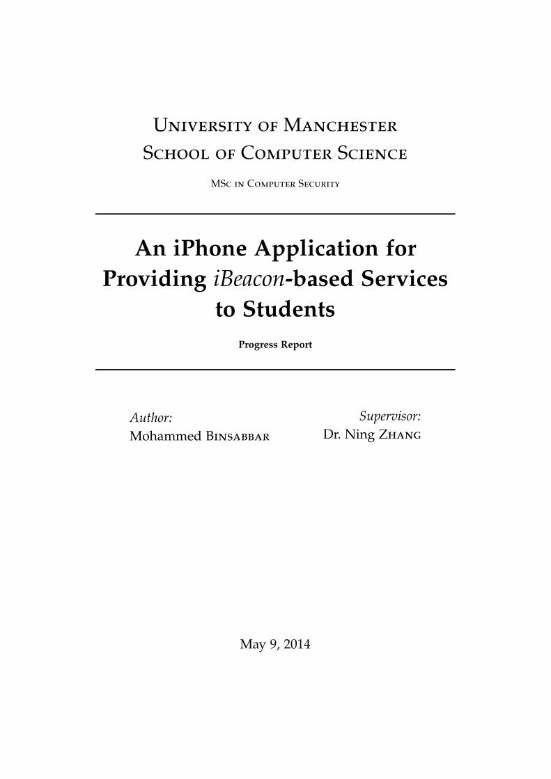
The selection of iBeacon emitter does not make a difference with regardto the iBeacon signal. Emitters will differ usually in signal range, devicesize, CPU and battery life. Estimote [4] was one of the first companiesto announce iBeacon emitters. Estimote provides the developer with aneasy to use API, which has been built on the top of Apple iBeacon API.Moreover, Estimote developers community is expanding. Estimote bea-cons are powered by a 32-bit ARM Cortext M0 CPU with a 256 KB flash.Figure 1 shows an Estimote beacon and its board.
3.5.2 Server Hosting
The design and implementation of the server infrastructure is not part ofthe project. However, the application that runs on the server is withinthe scope of the project. For this reason, an existing infrastructure solu-tion has been chosen. Heroku is a hosting service for server application.Heroku allows the developer to solely focus on the design of the appli-cation rather than the underlying infrastructure. Heroku takes care of allthe infrastructure design and security considerations. Heroku offers a setof servers to run the applications on. The choice of the server depends on
19
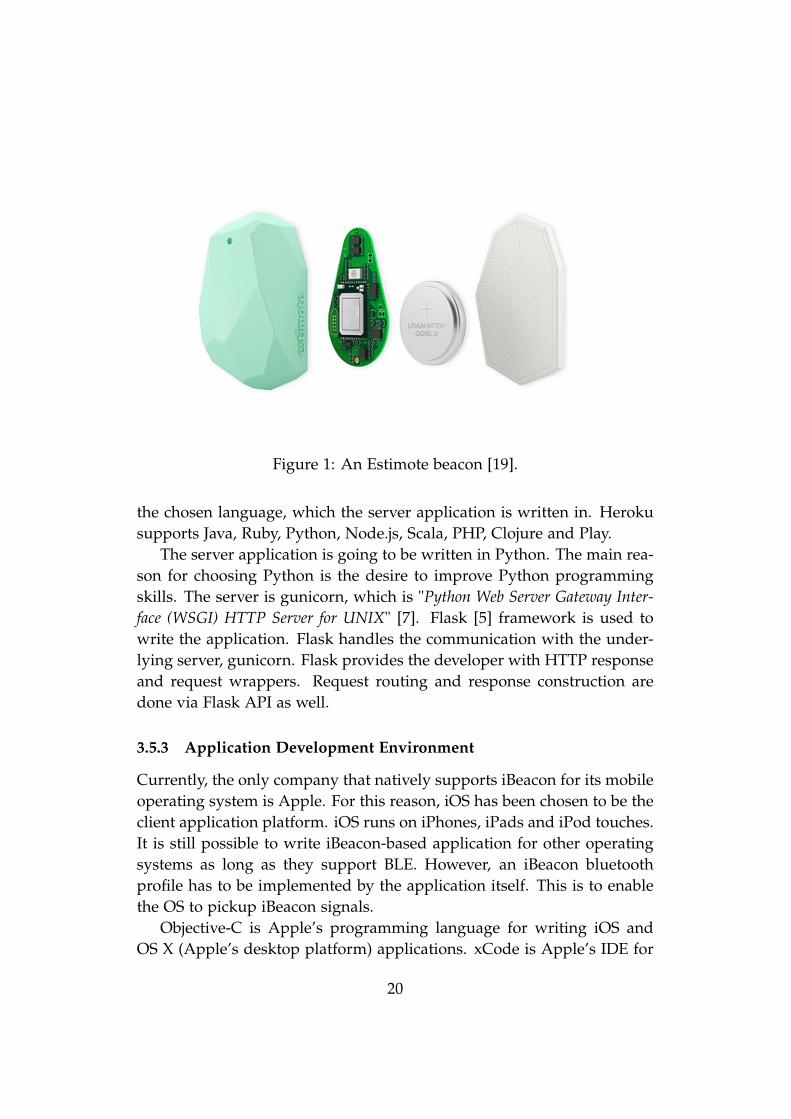
Figure 1: An Estimote beacon [19].
the chosen language, which the server application is written in. Herokusupports Java, Ruby, Python, Node.js, Scala, PHP, Clojure and Play.
The server application is going to be written in Python. The main rea-son for choosing Python is the desire to improve Python programmingskills. The server is gunicorn, which is "Python Web Server Gateway Inter-face (WSGI) HTTP Server for UNIX" [7]. Flask [5] framework is used towrite the application. Flask handles the communication with the under-lying server, gunicorn. Flask provides the developer with HTTP responseand request wrappers. Request routing and response construction aredone via Flask API as well.
3.5.3 Application Development Environment
Currently, the only company that natively supports iBeacon for its mobileoperating system is Apple. For this reason, iOS has been chosen to be theclient application platform. iOS runs on iPhones, iPads and iPod touches.It is still possible to write iBeacon-based application for other operatingsystems as long as they support BLE. However, an iBeacon bluetoothprofile has to be implemented by the application itself. This is to enablethe OS to pickup iBeacon signals.
Objective-C is Apple’s programming language for writing iOS andOS X (Apple’s desktop platform) applications. xCode is Apple’s IDE for
20
developing iOS and OS X applications. xCode is developed by Apple andavailable for free.
It is free to develop and test iOS application on an iOS simulator onthe OS X. However, in order to test the application on a physical deviceor distribute the application in Apple App Store, it is required to join iOSDeveloper Program, which costs $99 a year.
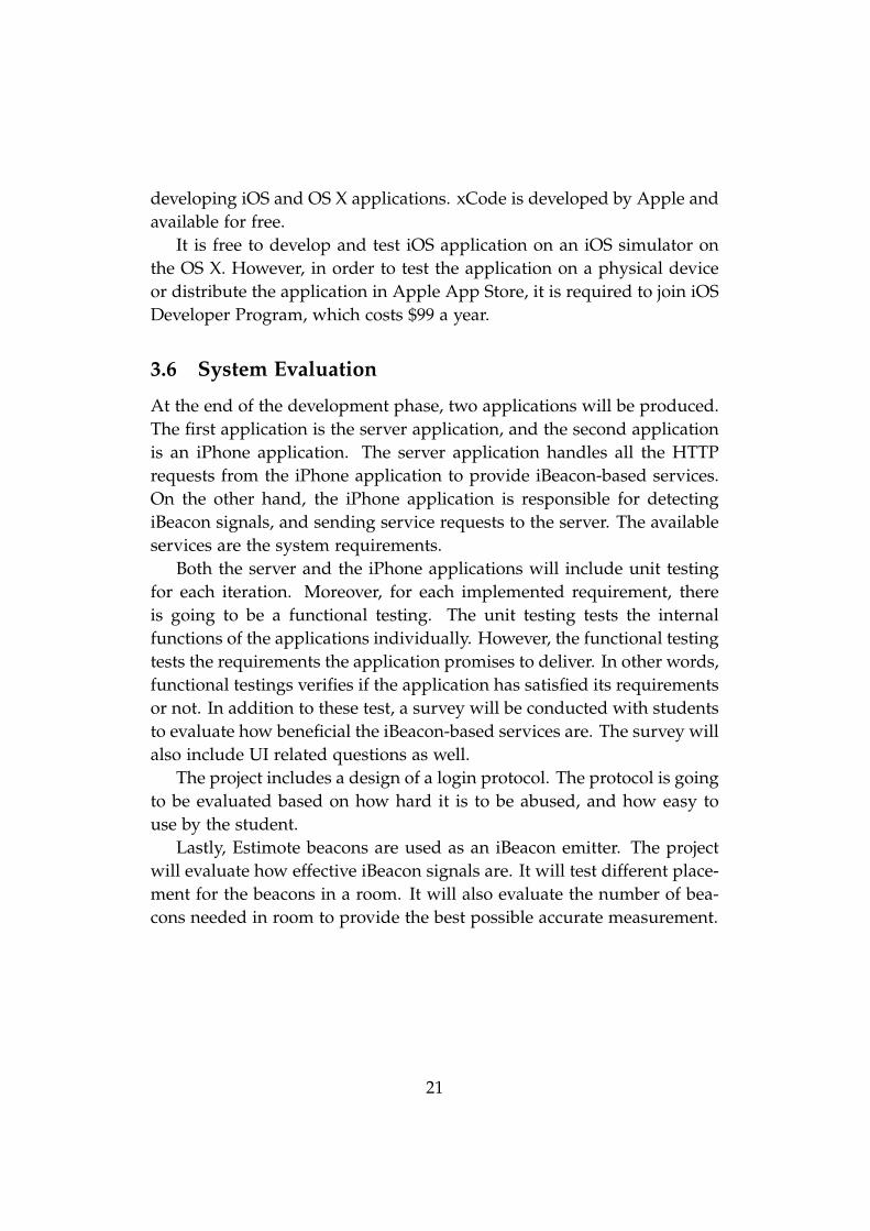
3.6 System Evaluation
At the end of the development phase, two applications will be produced.The first application is the server application, and the second applicationis an iPhone application. The server application handles all the HTTPrequests from the iPhone application to provide iBeacon-based services.On the other hand, the iPhone application is responsible for detectingiBeacon signals, and sending service requests to the server. The availableservices are the system requirements.
Both the server and the iPhone applications will include unit testingfor each iteration. Moreover, for each implemented requirement, thereis going to be a functional testing. The unit testing tests the internalfunctions of the applications individually. However, the functional testingtests the requirements the application promises to deliver. In other words,functional testings verifies if the application has satisfied its requirementsor not. In addition to these test, a survey will be conducted with studentsto evaluate how beneficial the iBeacon-based services are. The survey willalso include UI related questions as well.
The project includes a design of a login protocol. The protocol is goingto be evaluated based on how hard it is to be abused, and how easy touse by the student.
Lastly, Estimote beacons are used as an iBeacon emitter. The projectwill evaluate how effective iBeacon signals are. It will test different place-ment for the beacons in a room. It will also evaluate the number of bea-cons needed in room to provide the best possible accurate measurement.
21
4 Project Progress
This section discusses in details the work that has been done since March2014. It focuses on the design of a login protocol for the system.
4.1 Current System Requirements
The following are the current system requirements, which the projectaims at implementing:
• Logging in The System: The student must be able to use the iPhoneapplication to log in the system, so he can request a service.
• Taking Attendace: The student uses the iPhone application to takehis attendance. The application detects his location by picking upiBeacon signals and sending them to the server. The server checksthe student’s timetable, and marks his attendance if he has a lectureat the location and time in the request.
• Checking Room/Theatre Information: The student uses his iPhoneapplication to checks information related to the room he is in. Theapplication picks up iBeacon signals and sends them to the server.The server looks up the address of the room and returns room’sinformation.
• Booking Room/Theatre: The student uses his iPhone applicationto book a room he is in. The application sends the room’s iBeaconaddress to the server, then the server books the room if it is available.
4.2 Designing Login Protocol
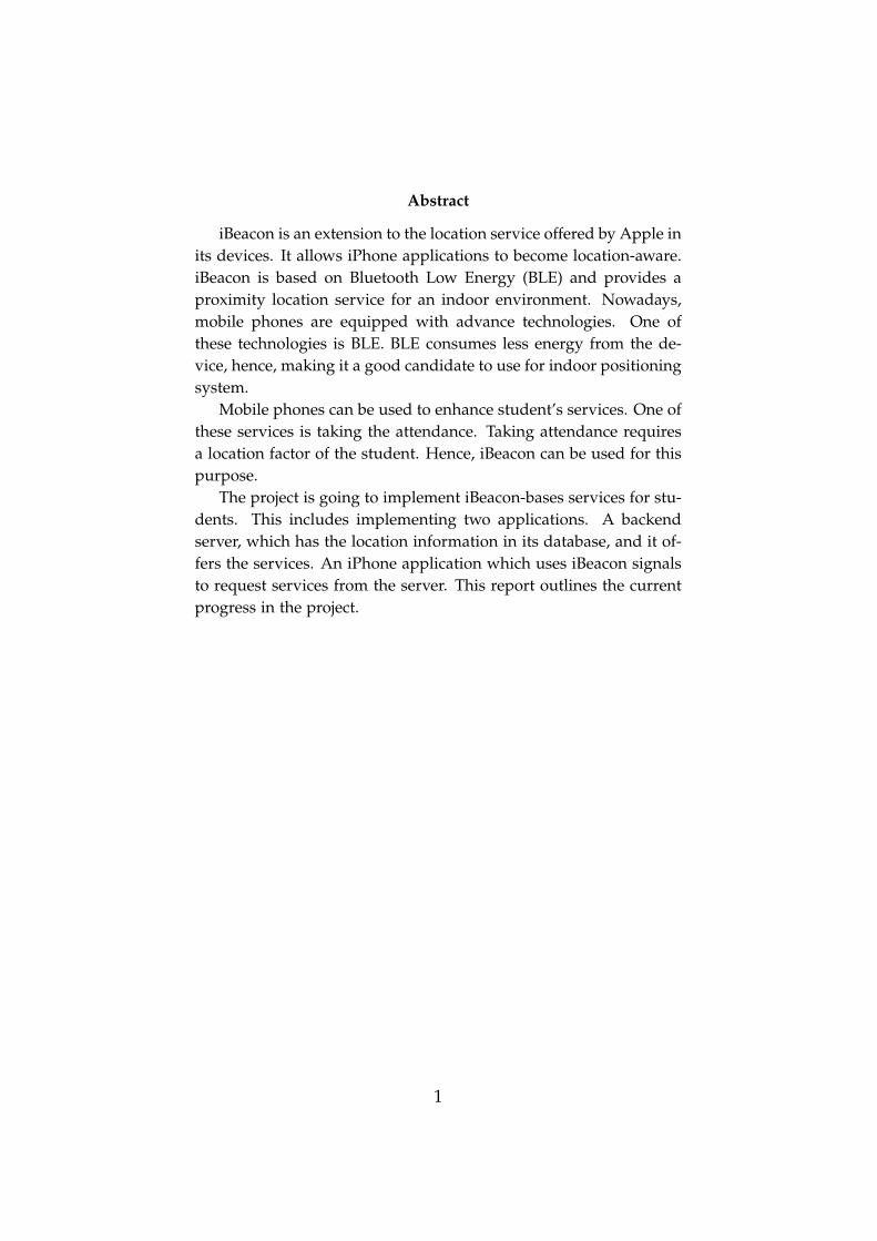
The system architecture is a client-server architecture, Figure 2. Studentservices are offered by the server and accessed via the internet by a mobileapplication. The internet is a dangerous place. Hence, security measure-ments must be considered. There are security requirements, that have tobe satisfied by the system, to protect it from being abused. The user ofthe mobile application is a student. The student has to log in to requestlocation-based service from the server.
22
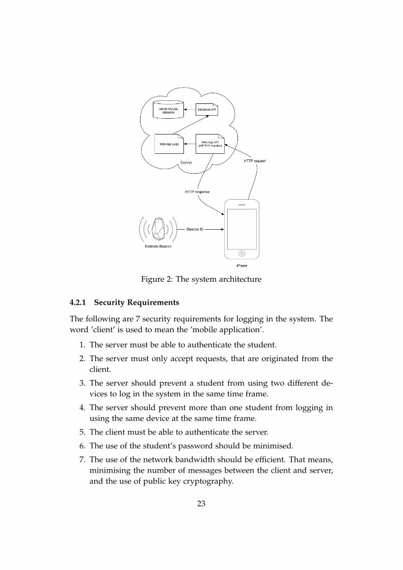
Figure 2: The system architecture
4.2.1 Security Requirements
The following are 7 security requirements for logging in the system. Theword ’client’ is used to mean the ’mobile application’.
1. The server must be able to authenticate the student.
2. The server must only accept requests, that are originated from theclient.
3. The server should prevent a student from using two different de-vices to log in the system in the same time frame.
4. The server should prevent more than one student from logging inusing the same device at the same time frame.
5. The client must be able to authenticate the server.
6. The use of the student’s password should be minimised.
7. The use of the network bandwidth should be efficient. That means,minimising the number of messages between the client and server,and the use of public key cryptography.
23
4.2.2 Assumptions
There are some assumptions that must be taken into account, which are:
1. The student is registered with the university and is already able touse the university’s wifi service.
2. The university enforces a strict password policy to ensure that astudent does not choose weak passwords, for example, short andcommon words.
3. The server has a table with all the registered students. It containsstudent IDs and hashed values of the students’ passwords.
4. Each student’s password is hashed with a different salt value. Boththe hashed password and the salt are stored in the server’s databasein different tables.
5. The server has a valid certificate. It is pinned in the iPhone appli-cation. Hence, it is possible to create a trusted self signed certificateby the server.
6. The student does not have an access to the application source code.
7. The server keeps record of students, who have unexpired servicepass. Each student ID has either 1 or 0 entry in the service passtable. An entry in the table means the student has an active servicepass. Otherwise, it means he does not an active session. Havingactive service pass allows him to request services without using hispassword.
8. The Estimote iBeacons are installed in secure places in the building.Hence, it is not possible to illegally change their places. Moreover,changing the address of an emitter is not possible without havingadmin privilege.
9. iBeacon signals are only broadcasted in a building, and the signalcannot be picked up from outside. Moreover, access to the buildingis guarded and requires a valid student ID.
4.3 The Login Protocol
The Login Protocol is divided into two protocols. The first protocol is usedwhen the client does not have a ServicePass. The second one is performed
24
when the client has an unexpired ServicePass, and wants to request aservice.
4.3.1 Abbreviations
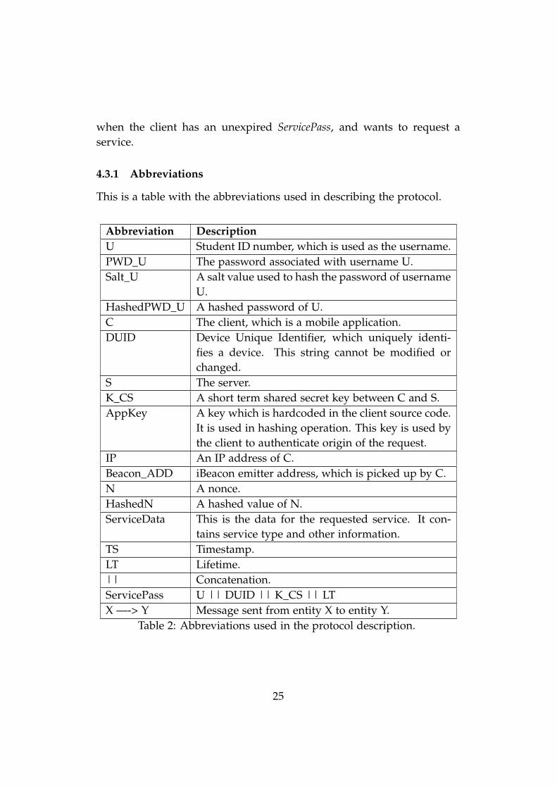
This is a table with the abbreviations used in describing the protocol.
Abbreviation DescriptionU Student ID number, which is used as the username.PWD_U The password associated with username U.Salt_U A salt value used to hash the password of username
U.HashedPWD_U A hashed password of U.C The client, which is a mobile application.DUID Device Unique Identifier, which uniquely identi-
fies a device. This string cannot be modified orchanged.
S The server.K_CS A short term shared secret key between C and S.AppKey A key which is hardcoded in the client source code.
It is used in hashing operation. This key is used bythe client to authenticate origin of the request.
IP An IP address of C.Beacon_ADD iBeacon emitter address, which is picked up by C.N A nonce.HashedN A hashed value of N.ServiceData This is the data for the requested service. It con-
tains service type and other information.TS Timestamp.LT Lifetime.|| Concatenation.ServicePass U || DUID || K_CS || LTX —-> Y Message sent from entity X to entity Y.
Table 2: Abbreviations used in the protocol description.
25
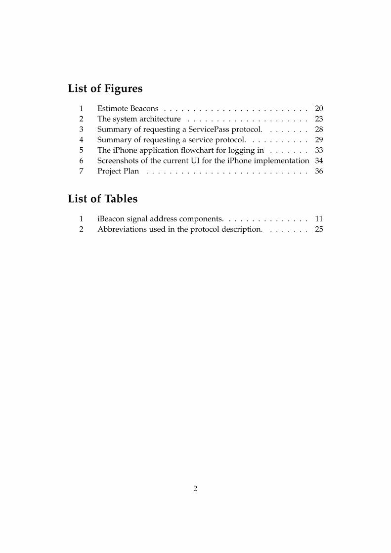
4.3.2 Requesting a ServicePass
The client performs the following three steps before performing the pro-tocol with the server:
• Asks the student for his student ID (U) and password (PWD_C).This is the only interaction between the student and the client.
• Initiates an SSL session with the server. During this step, the clientauthenticates the server by verifying the server certificate.
• Starts an SSL connection with the server.
Once the above steps have been performed, the login protocol starts:
1. At the Client Side:
1.1 Finds DUID. This is client platform dependent. Each clientplatform uses different approach to find this value. The valueis always consistent, even if the device is rebooted.
1.2 Detects two different iBeacon signals, that are the closest to it.1.3 Finds its IP address.1.4 Constructs a request and sends it to the server:
C —–> S: U || DUID || IP || Beacon_ADD || TS1
2. At the Server Side:
2.1 Validates the IP of the incoming request. The IP address isverified by checking that it is coming from the University ofManchester network address.
2.2 Validates Beacon_ADD in the request. The is done by checkingthe existence of the addresses in the server database. More-over, the two addresses must belong to the same location (sameroom/theatre/area).
2.3 Checks the existence of U by querying the server database.2.4 Checks its database for a valid ServicePass that is associated
with DUID. If there is a valid pass for the given DUID, thenthe associated student ID, U’, must be equal to U.
2.5 If there is no valid ServicePass associated with DUID, then theserver ensures that there is no other ServicePass’ for U withDUID’, where DUID’ != DUID.
26
2.6 If all the above validations pass, the server generates a nonceN1, finds the salt value of U, constructs a response and sendsit to the client:S —–> C: N1 || Salt_U || TS2
3. At the Client Side:
3.1 Concatenates PWD_U with Salt_U and hashes the result to pro-duce HashedPWD_U.
3.2 Concatenates HashedPWD_U with N1 and HMAC with AppKeyto compute HashedN1. AppKey is hardcoded in the applicationsource code.
3.3 Constructs a request and sends it to the server:C —–> S: HashedN1 || TS3
4. At the Server Side:
4.1 Finds the stored HashedPWD_U’ in its database.4.2 Finds its version of AppKey’.4.3 Computes HashedN1’ by HMAC(AppKey’, N1 || HashedPWD_U’).4.4 If HashedN1’ == HashedN1, the student is authenticated. Other-
wise, login error is returned to the client.4.5 If there is unexpired ServicePass, the server uses it. Otherwise,
the server generates K_CS, and associates it with U and DUID.The server specifies LT for K_CS. These informations are in-serted in the service pass table in the server’s database.
4.6 Sends ServicePass to the client:S —–> C: ServicePass || TS4
The login protocol is done after the client receives ServicePass. Theclient uses ServicePass for all the subsequent service requests to authenti-cate the student to the server.
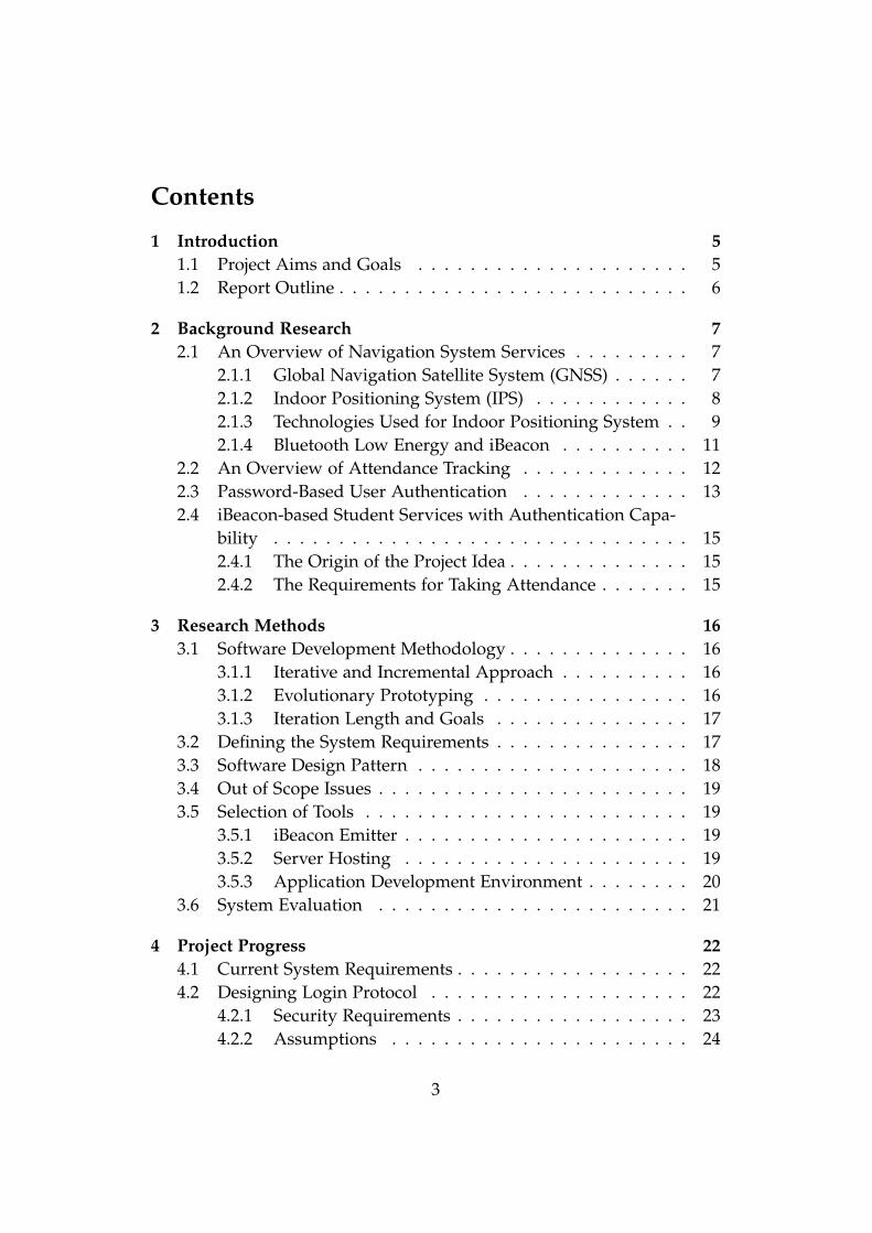
4.3.3 Requesting Service
This protocol is performed by the client, as long as it has obtained aServicePass. The following communication happens in insecure channel.Moreover, it does not require any student interaction, apart from selectinga service to request.
27
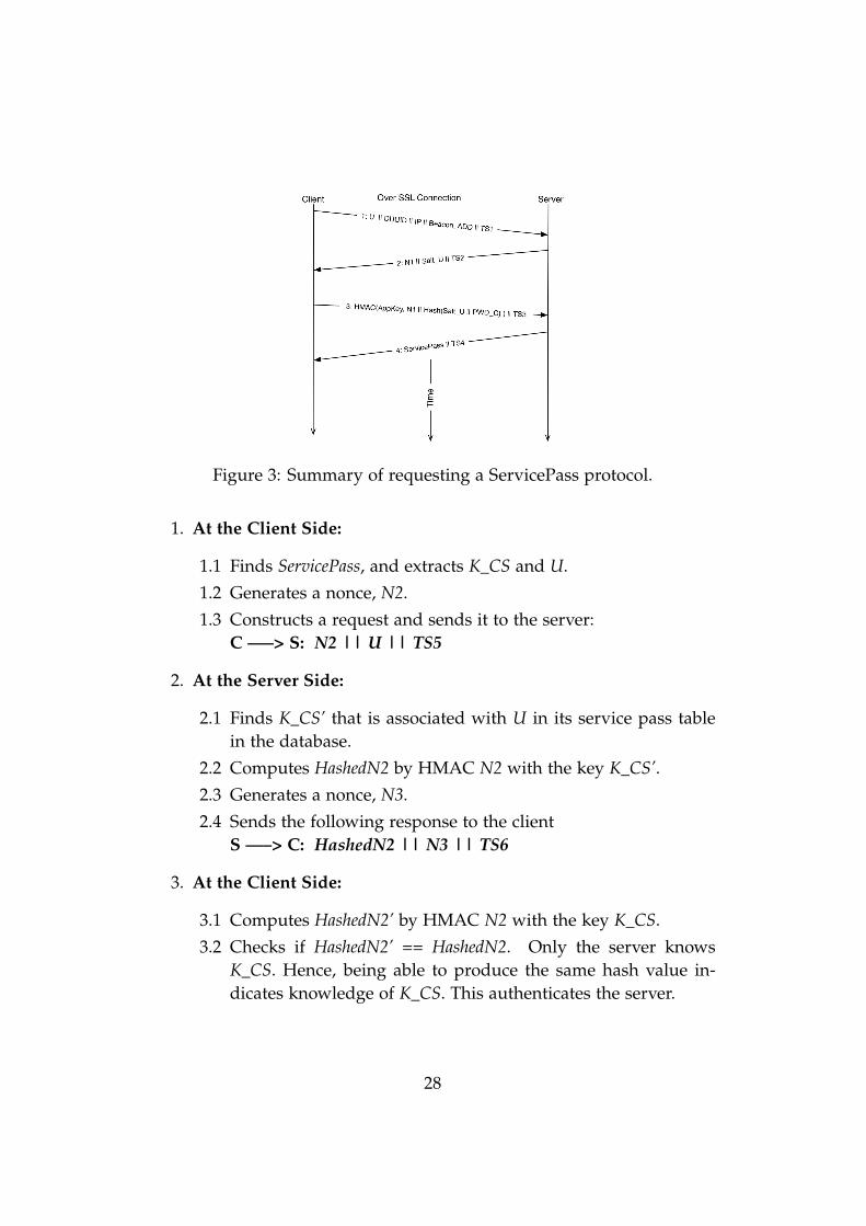
Figure 3: Summary of requesting a ServicePass protocol.
1. At the Client Side:
1.1 Finds ServicePass, and extracts K_CS and U.
1.2 Generates a nonce, N2.
1.3 Constructs a request and sends it to the server:C —–> S: N2 || U || TS5
2. At the Server Side:
2.1 Finds K_CS’ that is associated with U in its service pass tablein the database.
2.2 Computes HashedN2 by HMAC N2 with the key K_CS’.2.3 Generates a nonce, N3.
2.4 Sends the following response to the clientS —–> C: HashedN2 || N3 || TS6
3. At the Client Side:
3.1 Computes HashedN2’ by HMAC N2 with the key K_CS.
3.2 Checks if HashedN2’ == HashedN2. Only the server knowsK_CS. Hence, being able to produce the same hash value in-dicates knowledge of K_CS. This authenticates the server.
28
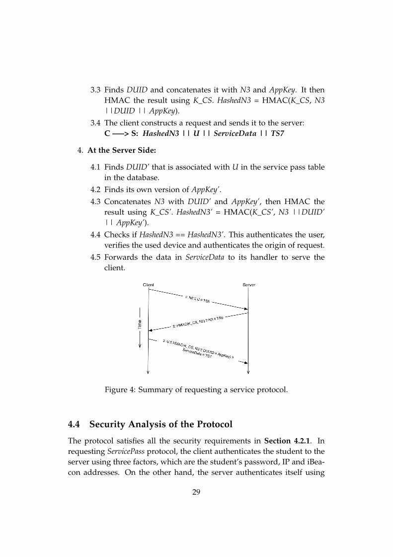
3.3 Finds DUID and concatenates it with N3 and AppKey. It thenHMAC the result using K_CS. HashedN3 = HMAC(K_CS, N3||DUID || AppKey).
3.4 The client constructs a request and sends it to the server:C —–> S: HashedN3 || U || ServiceData || TS7
4. At the Server Side:
4.1 Finds DUID’ that is associated with U in the service pass tablein the database.
4.2 Finds its own version of AppKey’.4.3 Concatenates N3 with DUID’ and AppKey’, then HMAC the
result using K_CS’. HashedN3’ = HMAC(K_CS’, N3 ||DUID’|| AppKey’).
4.4 Checks if HashedN3 == HashedN3’. This authenticates the user,verifies the used device and authenticates the origin of request.
4.5 Forwards the data in ServiceData to its handler to serve theclient.
Figure 4: Summary of requesting a service protocol.
4.4 Security Analysis of the Protocol
The protocol satisfies all the security requirements in Section 4.2.1. Inrequesting ServicePass protocol, the client authenticates the student to theserver using three factors, which are the student’s password, IP and iBea-con addresses. On the other hand, the server authenticates itself using
29
its certificate during the SSL handshake. The client has a valid servercertificate pinned in the source code. Pinning certificate allows the serverto use a self-signed certificate. When the server needs to update its cer-tificate, the client source code needs to be updated and pinned with thenew certificate. In the second protocol, a mutual authentication betweenthe server and the client is solely based on the knowledge of K_CS. BothRequirements 1 and 5 are satisfied.
To attack PWD_U, Salt_U must be obtained from the server. To ob-tain Salt_U, the attacker must connect to the university wifi and pickup two different iBeacon signals of the same location. Only authoriseduniversity’s users can connect to its WiFi network. Moreover, based onAssumption 11, an attacker will not be able to pickup iBeacon signal, un-less he is a student, or he uses a stolen student ID. Once the attackerobtains Salt_U, he can try to attack PWD_U. The difficulty of attackingPWD_U depends on its strength. Enforcing certain password policieshelps in hardening password attacks. Even if the attacker obtains Salt_Uto compute HashedPWD_U, he needs to know if the computed value isthe right one. This means knowledge of Salt_U does not help without thecorrect PWD_U, and he must try to log in until he succeeds. However,the system suspends user access after 5 incorrect login attempts.
AppKey is used by the client to authenticate the origin of the request.This is to satisfy Requirement 2. Given Assumption 6, extracting App-Key requires decompiling the binary file, then analysing the assemblycode. For the project case, the client is an iPhone application. Obtain-ing the source code requires jailbreaking the iPhone, which can be doneby a naive user. iOS decompiler generates only the header files and as-sembly codes. Hence, knowledge of assembly code is required. Debug-ging millions of lines of assembly code is a hard task and requires avery motivated and experienced attacker. There are some techniques toharden debugging the decompiled code, such as using meaningless vari-able/method names instead of obvious names.
The protocol records the logged in devices by associating DUID witheach valid ServicePass. DUID is consistence for each device. All the in-stalled application in once device share the same value. However, toabuse the use of DUID, the source code is required to patch, and the dif-ficult of this task is described previously. Moreover, because the serverauthenticates the origin of a request, then DUID must have been extracted
30
by the client, and has not been altered. The use of DUID is to satisfy bothRequirements 3 and 4.
Requirement 6 is satisfied by the use of ServicePass. The student useshis password only one time a day. The suggested lifetime of ServicePassis 8 hours. Given the fact the student has lectures from 9:00 to 17:00, then8 hours is a reasonable choice. Moreover, the use of ServicePass requiresonly use of secure hash algorithm, hence satisfying Requirement 7.
The use of nonce in the protocol prevents replay attacks. It enablesboth the server and client to ensure the request/response is fresh. Whenthe client generates nonce, it is keet for a short period of time, 2-3 sec-ond. If the response does not arrive within the specified time, the clientdiscards the nonce, so when it receives the nonce later, it refuses it. Theserver does exactly the same thing.
4.5 Selection of Hashing Algorithms
The protocol only makes use of hashing algorithms in its operations. Itis always advised to use tested and existing solutions rather than invent-ing new ones. Existing and recommended solutions have been designedand tested by security expertise. Currently, there are no practical attackson Secure Hash Algorithm with 256 bits output (SHA-256). Theoreticalattacks exist, however, current computing power makes them impracti-cal. [30]
SHA-256 is used for all the hashing purposes for the protocol. Thelength of AppKey must be 256 bits in this case, as it is used as a keyfor HMAC in the first protocol. Moreover, K_CS must be 256 bits long,because the mutual authentication in the second protocol is based onusing it as a key for the HMAC. AppKey, K_CS and nonces are generatedusing secure random number generator. Each programming languageprovides its implementation for generating secure random keys. In theproject case, Python is used at the server side, and it provides a functionin its random package to generate secure random keys [11]. At the clientside, Apple provides a function in its Security framework [12].
31
4.6 Current Implementation
The main goal of the first iteration was to setup the development envi-ronment and install the required third party frameworks.
4.6.1 The Server Application
The server application implementation focused on implementing the firstlogin protocol. The current implementation of the protocol in the appli-cation is not complete. For example, the current implementation doesnot check for the IP address of incoming request. Also, currently all thepasswords were hashed with the same salt value. Moreover, the currentimplementation was tested locally, and has not been pushed to Herokuservers yet.
The current application accepts only HTTPS ‘PUT’ request for loggingin the system. The data format the application accepts is JSON. BecauseHTTP is stateless protocol, the server uses short life sessions in order tosave the state of last HTTP request the server receives from the client.
4.6.2 The iPhone Application
The iPhone implementation has been smoother and faster due to usingiPhone IDE. In the server application implementation, no IDE was used.Hence managing and organising files added extra time.
The protocol requires use of unique device identifier that is alwaysconsistent. However, Apple has deprecated the method, that returns theiPhone unique identifier. This value is guaranteed to be unique for everyiPhone Apple makes. The reason for deprecating the method was toprotect the user privacy. Apple provides an alternative solution, whichreturns a vendor identifier. However, as described by Apple "The valueof this property is the same for apps that come from the same vendor runningon the same device. A different value is returned for apps on the same devicethat come from different vendors, and for apps on different devices regardless ofvendor" [13]. Moreover, the value changes when all the vendor’s apps aredeleted and one of them is reinstalled later.
OpenUDID [10] is an open source framework, and it aims at ad-dressing the previously mentioned problem. The value generated by
32
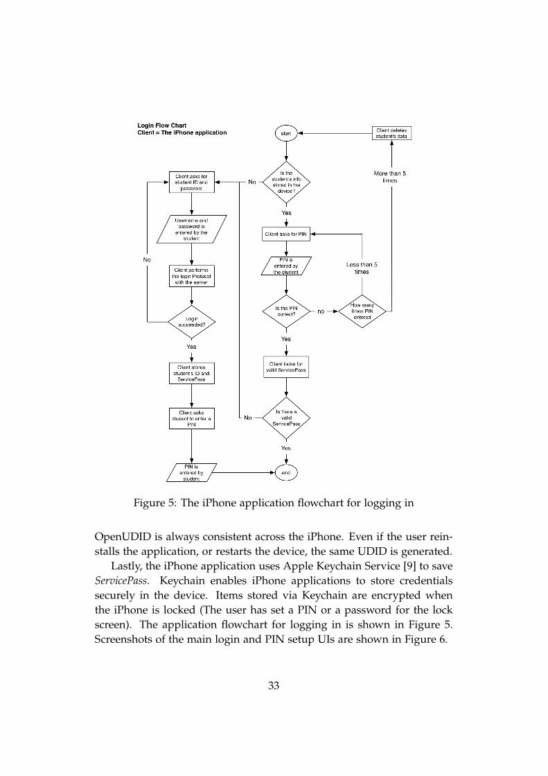
Figure 5: The iPhone application flowchart for logging in
OpenUDID is always consistent across the iPhone. Even if the user rein-stalls the application, or restarts the device, the same UDID is generated.
Lastly, the iPhone application uses Apple Keychain Service [9] to saveServicePass. Keychain enables iPhone applications to store credentialssecurely in the device. Items stored via Keychain are encrypted whenthe iPhone is locked (The user has set a PIN or a password for the lockscreen). The application flowchart for logging in is shown in Figure 5.Screenshots of the main login and PIN setup UIs are shown in Figure 6.
33
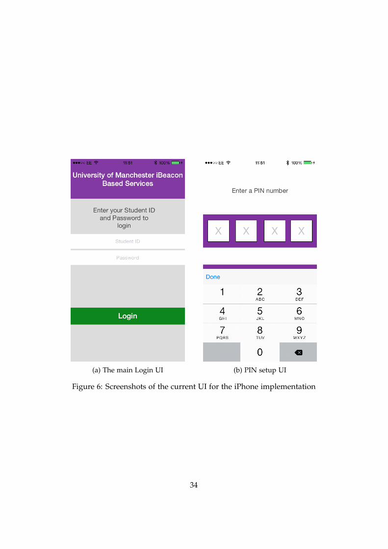
(a) The main Login UI (b) PIN setup UI
Figure 6: Screenshots of the current UI for the iPhone implementation
34
5 Conclusion and Future Work
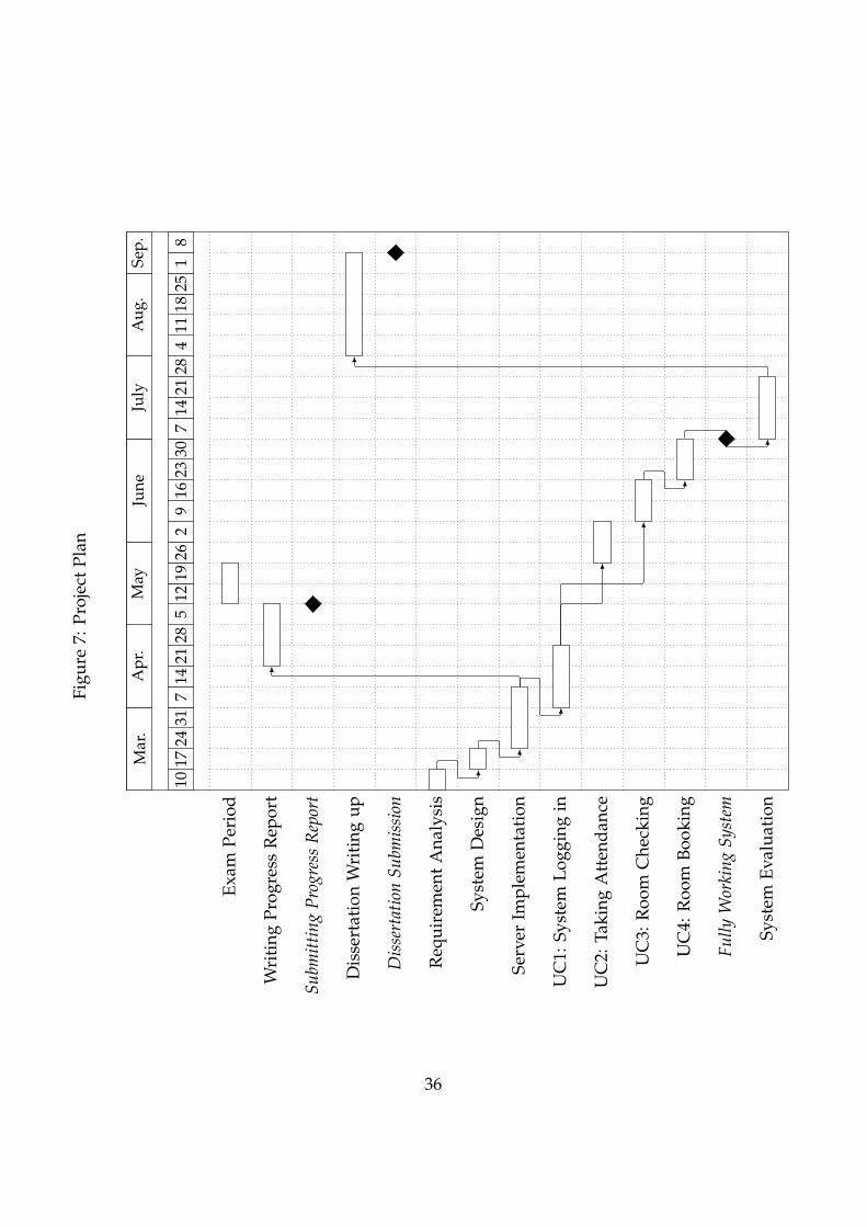
The prototype produced in the previous iteration is going to be refinedto fix some of the bugs. The main focus for the coming iteration is to fixthe bugs and produce a prototype that fully implements the protocol atboth ends. Once this is done, the project will focus on implementing thelocation-based student services. The coming iterations will implementthese requirements in this order; Take Attendance, Checking Room Availabil-ity and Booking a Room. Some new requirements might appear, however,the project will focus on perfectly implementing the aforementioned threerequirements. Each iteration is going to be a maximum of two weeks. Fig-ure 7 shows the project plan as Gantt Chart. The Gantt Chart timeline isdivided as weeks. The numbers in the 2nd row show the start date of theweek.
iBeacon is a new IPS implemented by Apple. It makes mobile deviceswith BLE support to become location-aware. iBeacon does not requiresetup at the mobile device, apart from defining iBeacon profile. Appledevices already support iBeacon. Because iBeacon is BLE, it does notconsume huge energy from the device.
A mobile application can be built to provide iBeacon-based services tothe students. The application can make attendance taking an easy task.Moreover, the application can allow a student to a book a room, that heis in, if it is available. The student does not have to know the name ofroom. The application makes use of iBeacon to detect the student currentlocation, and request a service from a backend server. The system can beexpanded in the future to support more functions, such as navigation inthe building.
35
Figu
re7:
Proj
ect
Plan
Mar
.A
pr.
May
June
July
Aug
.Se
p.
1017
2431
714
2128
512
1926
29
1623
307
1421
284
1118
251
8
Exam
Peri
od
Wri
ting
Prog
ress
Rep
ort
Subm
ittin
gPr
ogre
ssR
epor
t
Dis
sert
atio
nW
riti
ngup
Dis
sert
atio
nSu
bmis
sion
Req
uire
men
tA
naly
sis
Syst
emD
esig
n
Serv
erIm
plem
enta
tion
UC
1:Sy
stem
Logg
ing
in
UC
2:Ta
king
Att
enda
nce
UC
3:R
oom
Che
ckin
g
UC
4:R
oom
Book
ing
Fully
Wor
king
Syst
em
Syst
emEv
alua
tion
36
References
[1] Apple push notification service. [Online; Accessed: 30March 2014. Available at: https://developer.apple.com/library/ios/documentation/NetworkingInternet/Conceptual/RemoteNotificationsPG/Chapters/ApplePushService.html.
[2] Attendance tracking. [Online; Accessed: 28 Feb 2014. Avail-able at: http://www.its.txstate.edu/departments/classroom_technology/attendancetracking.html.
[3] Ekahau; rfid-over-wi-fi tracking systems, rtls and wlan site survey.[Online; Accessed: 15 Feb 2014. Available at: http://www.ekahau.com.
[4] Estimote. [Online; Accessed: 17 March 2014. Available at: http://estimote.com].
[5] Flask. [Online; Accessed: 1 April 2014. Available at: http://flask.pocoo.org].
[6] Frequently asked questions about two-step verification for apple id.[Online; Accessed: 30 March 2014. Available at: http://support.apple.com/kb/ht5570.
[7] Gunicorn. [Online; Accessed: 1 April 2014. Available at: http://gunicorn.org].
[8] Install google authenticator. [Online; Accessed: 30 March2014. Available at: https://support.google.com/accounts/answer/1066447?hl=en.
[9] Keychain services concepts. [Online; Accessed: 16 April 2014.Available at: https://developer.apple.com/library/mac/documentation/security/conceptual/keychainServConcepts/02concepts/concepts.html].
[10] OpenUDID. [Online; Accessed: 3 March 2014. Available at: https://github.com/ylechelle/OpenUDID].
37
[11] Python, random - generates pseudo-random numbers. [Online; Ac-cessed: 10 April 2014. Available at: https://docs.python.org/2/library/random.html#random.SystemRandom].
[12] Randomization services reference. [Online; Accessed: 16 April2014. Available at: https://developer.apple.com/library/ios/documentation/security/reference/randomizationreference/Reference/reference.html].
[13] UIDevice Class Reference: identifierForVendor. [Online; Ac-cessed: 16 April 2014. Available at: https://developer.apple.com/library/ios/documentation/uikit/reference/UIDevice_Class/Reference/UIDevice.html#//apple_ref/occ/instp/UIDevice/identifierForVendor].
[14] GPS.gov: Road & Highway Applications. http://www.gps.gov/applications/roads/, 2006. [Online; Accessed: 7 Feb 2014].
[15] BBC News Technology: China’s Beidou GPS-substitute opens topublic in Asia. http://www.bbc.co.uk/news/technology-20852150,December 2012. [Online; Accessed: 7 Feb 2014].
[16] GPS.gov: Timing Applications. http://www.gps.gov/applications/timing/, September 2013. [Online; Accessed: 7Feb 2014].
[17] iOS: Understanding iBeacon. Article, Apple Inc., http://support.apple.com/kb/HT6048?viewlocale=en_US&locale=en_US, 2013. [On-line; Accessed: 28 Jan 2014].
[18] Galileo: Satellite launches. http://ec.europa.eu/enterprise/policies/satnav/galileo/satellite-launches/index_en.htm,January 2014. [Online; Accessed: 7 Feb 2014].
[19] Preorder for estimote beacons available, shipping this sum-mer. Article, Estimote, July 2014. [Online; Accessed: 28 Jan2014. Available at: http://blog.estimote.com/post/57087851702/preorder-for-estimote-beacons-available-shipping-this].
[20] P. Bahl and V.N. Padmanabhan. Radar: an in-building rf-based userlocation and tracking system. In INFOCOM 2000. Nineteenth Annual
38
Joint Conference of the IEEE Computer and Communications Societies. Pro-ceedings. IEEE, volume 2, pages 775–784 vol.2, 2000.
[21] Mohammed Binsabbar. iStudentPocket: An iOS Application for TheSchool of Computer Science to Organise Students and Provide Themwith Easy Access to Their Academic Records. Final Year ProjectReport, School of Computer Science, University of Manchester, April2013.
[22] Mehmet F. Dicle and John Levendis. Using RFID technology to trackattendance. Economic Educators, 13(1):29–38, 2013.
[23] Jay Donovan. Wifarer Brings Indoor Navigation To TheRoyal BC Museum. http://techcrunch.com/2012/08/01/wifarer-brings-indoor-navigation-to-the-royal-bc-museum/,August 2012. [Online; Accessed: 10 Feb 2014].
[24] Tom Farley. Mobile telephone history. Telektronikk, 101(3/4):22–34,2005.
[25] Erich Gamma, Richard Helm, Ralph Johnson, and John Vlissides. De-sign Patterns: Elements of Reusable Object-oriented Software. Addison-Wesley Longman Publishing Co., Inc., 1995.
[26] Gartner, Inc. Gartner Says Smartphone Sales Grew 46.5 Percentin Second Quarter of 2013 and Exceeded Feature Phone Sales forFirst Time. Press Release, August 2013. http://www.gartner.com/newsroom/id/2573415.
[27] Larry Greenemeier. A Positioning System That Goes Where GPSCan’t. Scientific American, January 2008.
[28] Yanying Gu, Anthony Lo, and Ignas Niemegeers. A Survey of IndoorPositioning Systems for Wireless Personal Networks. IEEE COMMU-NICATIONS SURVEYS & TUTORIALS, 11(1), 2009.
[29] Natalie Harrison and Teresa Brewer. Apple LaunchesiPhone 4S, iOS 5 and iCloud. online, October 2011.Available at: https://www.apple.com/pr/library/2011/10/04Apple-Launches-iPhone-4S-iOS-5-iCloud.html.
39
[30] Mario Lamberger and Florian Mendel. Higher-order differential at-tack on reduced sha-256. IACR Cryptology ePrint Archive, 2011:37,2011.
[31] Craig Larman. Applying UML and Patterns: An Introduction to Object-Oriented Analysis and Design and Iterative Development (3rd Edition).Prentice Hall PTR, 2004.
[32] S. Grewal Mohinder, R. Weill Lawrence, and P. Andrews Angus.Global Positioning Systems, Inertial Navigation, and Integration. JohnWiley & Sons, 2 edition, 2007.
[33] Ginger Myles, Adrian Friday, and Nigel Davies. Preserving Privacyin Environments with Location-Based Applications. Pervasive Com-puting, IEEE, 2(1):56 – 64, 2003.
[34] Mary Catherine O’Connor. Northern Arizona University to useexisting rfid student cards for attendance tracking. RFID journal,2010. [Online; Accessed: 28 Feb 2014. Available at: http://www.rfidjournal.com/articles/view?7628].
[35] P.Veeranath, Dr.D.N.Rao, Dr.Srinivasn Vathsal, and Bhasker Nalaveli.Reducing Multipath Effects in Indoor Channel for Analysis ofGPS/Pseudolite Signal Acquisition. International Journal of Scientificand Research Publications, 3(2), February 2013.
[36] David Schneider. New Indoor Navigation Technologies WorkWhere GPS Can’t. http://spectrum.ieee.org/telecom/wireless/new-indoor-navigation-technologies-work-where-gps-cant,November 2013. [Online; Accessed: 7 Feb 2014].
[37] William Stallings. User authentication. In CRYPTOGRAPHY ANDNETWORK SECURITY PRINCIPLES AND PRACTICE, chapter 15.Prentice Hall, 5th edition, 2011.
[38] Hema Subramaniam, Marina Hassan, and Setyawan Widyarto. BarCode Scanner Based Student Attendance System (SAS). TICOM,1(3):173–177, January 2013.
40
[39] Kiran Thapa and Steven Case. An Indoor Positioning Service for Blue-tooth Ad Hoc Networks. Technical report, Department of Computer &Information Sciences, Minnesota State University, Mankato, 2003.
[40] Roy Want, Andy Hopper, Veronica Falcão, and Jonathan Gibbons.The active badge location system. ACM Transactions on InformationSystems, 10(1):91–102, January 1992.
[41] Andy Ward, A. Jones, and A. Hopper. A new location technique forthe active office. Personal Communications, IEEE, 4(5):42–47, Oct 1997.
41