Embed Size (px)
Citation preview
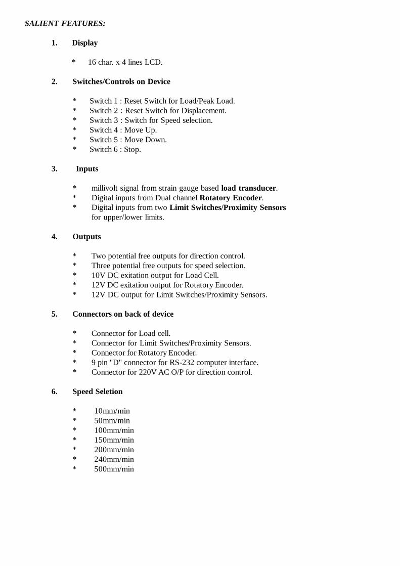
Computerised Foam Testing MachineModel No.-0601-6001
Installation & Operating Manual
Fully Automatic Process Control for Standards
* IS 7888 (6.3.2)* IS 7888 (6.3.3) [40%]* IS 7888 (6.3.3) [50%]* SABS 640* JIS K6400 (Method A)* JIS K6400 (Method B)* JIS K6400 (Method C)* JIS K6400 (Method D)* ISO 2439 (Method A)* ISO 2439 (Method B)* ISO 2439 (Method C)* ASTM D3574 (Test B1)* ASTM D3574 (Test B2)
Embedded System Laboratories Pvt. Ltd. (An ISO 9001:2008 certified company)
86, Lane No. 7, Near Laxmi Dairy, Gurudwara Road, Jawahar Colony,N.I.T. Faridabad-121005, Haryana (India)
Mobile : +91-9811482048, +91-9311482051, Phone : 0091-129-2230671E-mail :[email protected], [email protected], [email protected]
Visit us at : www.eslpl.com

INTRODUCTION
Embedded System Laboratories Pvt. Ltd. is a company which is involved indevelopments and manufacturing in the field of Embedded Systems and miscellaneousSensors/Transducers.
The company activities includes to serve the laboratories which are involvedin Quality Controls either in measurments of various parameters or developing otherprocess controls for the same.
Company's product includes Load cell, Pressure Transducer and their Indicators& Controller, SMS enabled security systems & Process Control Systems
All the devices of the company are designed for a user friendly operation. Specialattention is given to the software for the devices to set the various parameters at theuser end if they want to change any, like Calibration, Limits, other setting, of thedevice etc.
Providing high quality on low price.
SALIENT FEATURES:
1. Display
* 16 char. x 4 lines LCD.
2. Switches/Controls on Device
* Switch 1 : Reset Switch for Load/Peak Load.* Switch 2 : Reset Switch for Displacement.* Switch 3 : Switch for Speed selection.* Switch 4 : Move Up.* Switch 5 : Move Down.* Switch 6 : Stop.
3. Inputs
* millivolt signal from strain gauge based load transducer.* Digital inputs from Dual channel Rotatory Encoder.* Digital inputs from two Limit Switches/Proximity Sensors
for upper/lower limits.
4. Outputs
* Two potential free outputs for direction control.* Three potential free outputs for speed selection.* 10V DC exitation output for Load Cell.* 12V DC exitation output for Rotatory Encoder.* 12V DC output for Limit Switches/Proximity Sensors.
5. Connectors on back of device
* Connector for Load cell.* Connector for Limit Switches/Proximity Sensors.* Connector for Rotatory Encoder.* 9 pin "D" connector for RS-232 computer interface.* Connector for 220V AC O/P for direction control.
6. Speed Seletion
* 10mm/min* 50mm/min* 100mm/min* 150mm/min* 200mm/min* 240mm/min* 500mm/min
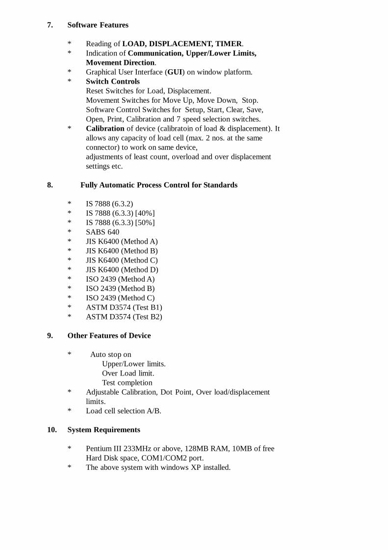
7. Software Features
* Reading of LOAD, DISPLACEMENT, TIMER.* Indication of Communication, Upper/Lower Limits,
Movement Direction.* Graphical User Interface (GUI) on window platform.* Switch Controls
Reset Switches for Load, Displacement.Movement Switches for Move Up, Move Down, Stop.Software Control Switches for Setup, Start, Clear, Save,Open, Print, Calibration and 7 speed selection switches.
* Calibration of device (calibratoin of load & displacement). Itallows any capacity of load cell (max. 2 nos. at the sameconnector) to work on same device,adjustments of least count, overload and over displacementsettings etc.
8. Fully Automatic Process Control for Standards
* IS 7888 (6.3.2)* IS 7888 (6.3.3) [40%]* IS 7888 (6.3.3) [50%]* SABS 640* JIS K6400 (Method A)* JIS K6400 (Method B)* JIS K6400 (Method C)* JIS K6400 (Method D)* ISO 2439 (Method A)* ISO 2439 (Method B)* ISO 2439 (Method C)* ASTM D3574 (Test B1)* ASTM D3574 (Test B2)
9. Other Features of Device
* Auto stop onUpper/Lower limits.Over Load limit.Test completion
* Adjustable Calibration, Dot Point, Over load/displacementlimits.
* Load cell selection A/B.
10. System Requirements
* Pentium III 233MHz or above, 128MB RAM, 10MB of freeHard Disk space, COM1/COM2 port.
* The above system with windows XP installed.
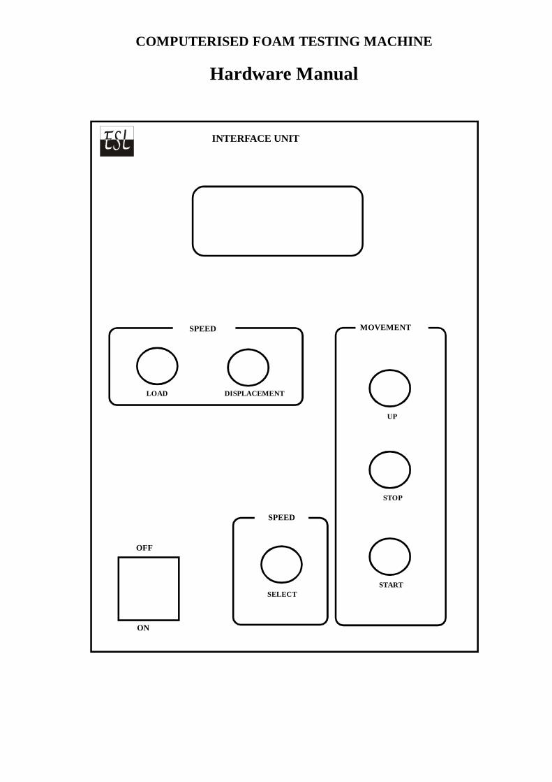
MOVEMENTSPEED
OFF
ON
INTERFACE UNIT
LOAD DISPLACEMENT
SPEED
UP
STOP
STARTSELECT
COMPUTERISED FOAM TESTING MACHINE
Hardware Manual

Load Cell
Encoder
Fuse
+VE -VE Up.lt. L. Lt.
RS232
220v AC
NO6 COM NO5 COM NO4 COM NO3 COM NO2 COM NO1 COM
4 Pin roundconnector
5 Pin roundconnector
4 Pin L-typeconnector
12 Pin connector
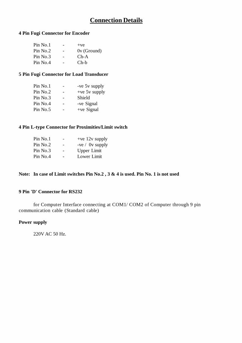
Connection Details
4 Pin Fugi Connector for Encoder
Pin No.1 - +vePin No.2 - 0v (Ground)Pin No.3 - Ch-APin No.4 - Ch-b
5 Pin Fugi Connector for Load Transducer
Pin No.1 - -ve 5v supplyPin No.2 - +ve 5v supplyPin No.3 - ShieldPin No.4 - -ve SignalPin No.5 - +ve Signal
4 Pin L-type Connector for Proximities/Limit switch
Pin No.1 - +ve 12v supplyPin No.2 - -ve / 0v supplyPin No.3 - Upper LimitPin No.4 - Lower Limit
Note: In case of Limit switches Pin No.2 , 3 & 4 is used. Pin No. 1 is not used
9 Pin 'D' Connector for RS232
for Computer Interface connecting at COM1/ COM2 of Computer through 9 pincommunication cable (Standard cable)
Power supply
220V AC 50 Hz.

} for speed control through AC drive
} for UP & DOWN movement through AC drive.
12 Pin Connector for ContactorsCom1 -NO1 -Com2 -NO2 -Com3 -NO3 -Com4 -NO4 -Com5 -NO5 -Com6 -No6 -
Speed Selection
O/P1 O/P2 O/P3 mm/min1 0 0 100 1 0 501 1 0 1000 0 1 1501 0 1 2000 1 1 2401 1 1 500
Direction Selection
O/P4 O/P50 0 Stop1 0 UP1 1 Down
Note : These COM & NO points are potential free and independent to each other.
} not in use.
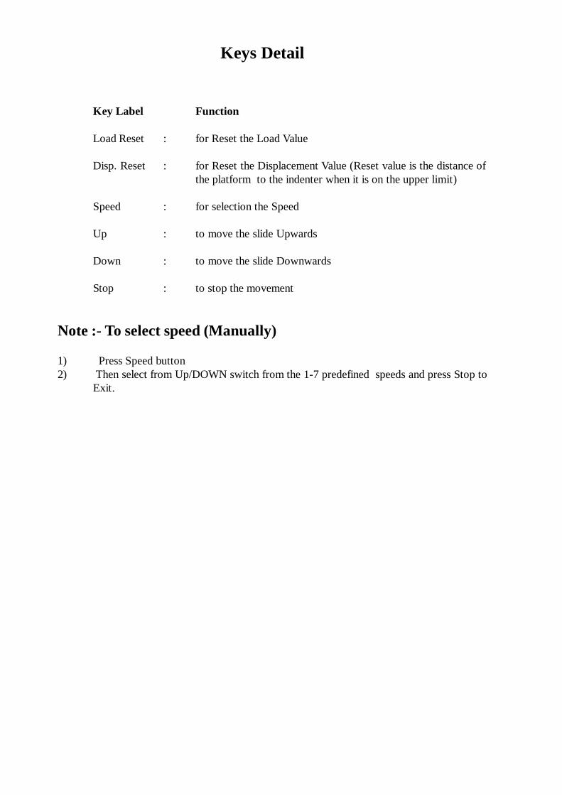
Key Label Function
Load Reset : for Reset the Load Value
Disp. Reset : for Reset the Displacement Value (Reset value is the distance ofthe platform to the indenter when it is on the upper limit)
Speed : for selection the Speed
Up : to move the slide Upwards
Down : to move the slide Downwards
Stop : to stop the movement
Note :- To select speed (Manually)
1) Press Speed button2) Then select from Up/DOWN switch from the 1-7 predefined speeds and press Stop to
Exit.
Keys Detail

Installation Preparation
To install the device you should have the followings
1. Interface Unit (ie., 0601-6001).
2. RS232 (9 pin) Communication Cable.
3. One or Two Load Cells (4 wire) of your desired capacity having 2mV/V outputs.
4. A Rotatory Encoder having dual channel output with 90 degree shift in both outputs.
5. Two Proximity Switches (n-p-n, NO), or two Limit Switches.
6. Compatible frequency/DC drive with direction and speed control.
7. Pentium III or above with CD Drive, 128MB RAM, 10MB of free Hard Disk space,COM1/
COM2 port , Windows XP installed.
8. CD of the software "ESL : Computerised Foam Testing Machine"
How to Install the Interface Unit?
To install the device follow the steps
1. Make the Connections of all the sensors, transducers, contactors etc. as per the details given in
this manual under 'Connection Details' topic.
2. Install the Software by putting CD in CD ROM Drive, just double click setup.exe file and
follow the instructions.
3. Switch ON the device. Start the Software and select the COM Port as mentioned in this
manual in topic 'H ow to set COM Port and Star t the Software '. The default passward for
software/calibration is 123.4. Make sure that the Communication Icon is showing that the device is plugged in.
5. Check that by giving the load on load cell, the readings of Load will increase. (if decreasing
then swap the signal wires).
6. Check that by pressing the UP/DOWN switch, the slide is going to the respective direction.
7. Check that by moving the indenter down (use DOWN switch), the Displacement values should
decrease (if increasing then swap the Channels cables).
8. Check that on arriving the Upper/Lower Limit their respective indication is displayed in the
Software Interface. If opposite, swap the Limit Cables or it may cause accident.
9. Calibrate the load values. The method for calibrating Load is given under the topic "How toCalibrate the 'Load' " in this manual.
10. Calibrate the displacement values. The method for calibrating displacement is given under the
topic "How to Calibrate the Displacement" in this manual.
If everything goes right, your device installation is complete.

Software Introduction
The software is designed for the Windows XP based platform.
The software communicates on the Serial Port (eg. COM1) and also shows the communication status on
interface.How to set the COM Port and Start the Software
In windows Click the 'Start Menu', select 'Programs' then 'Foam Testing Machine'. There
are ' COM Port Setting' & 'Foam Testing Machine' shortcuts. Select the 'COM Port Setting. This
action will open communication setting window as shown in figure no.1. Type the COM Port
number and press OK button. There will be a message showing you the availability of COM Port.
If COM Port is available, click EXIT. Your device will now communicate through this Port when
you start Foam Testing Machine software.
Figure No. 1
After setting the COM Port click the 'Start Menu' again select 'Programs' then ''Foam
Testing Machine', select the 'Foam Testing Machine' shortcut . This action will open the
permission check window as shown in figure 2.
Figure No. 2
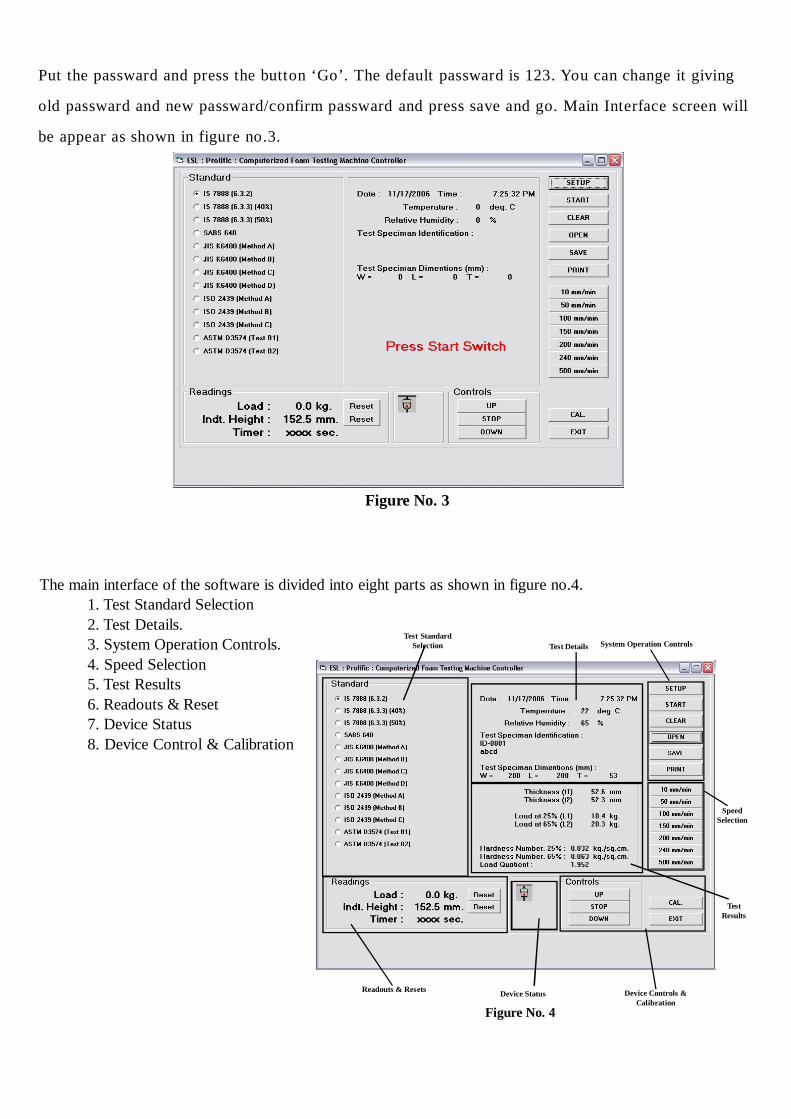
Figure No. 3
Put the passward and press the button ‘Go’. The default passward is 123. You can change it giving
old passward and new passward/confirm passward and press save and go. Main Interface screen will
be appear as shown in figure no.3.
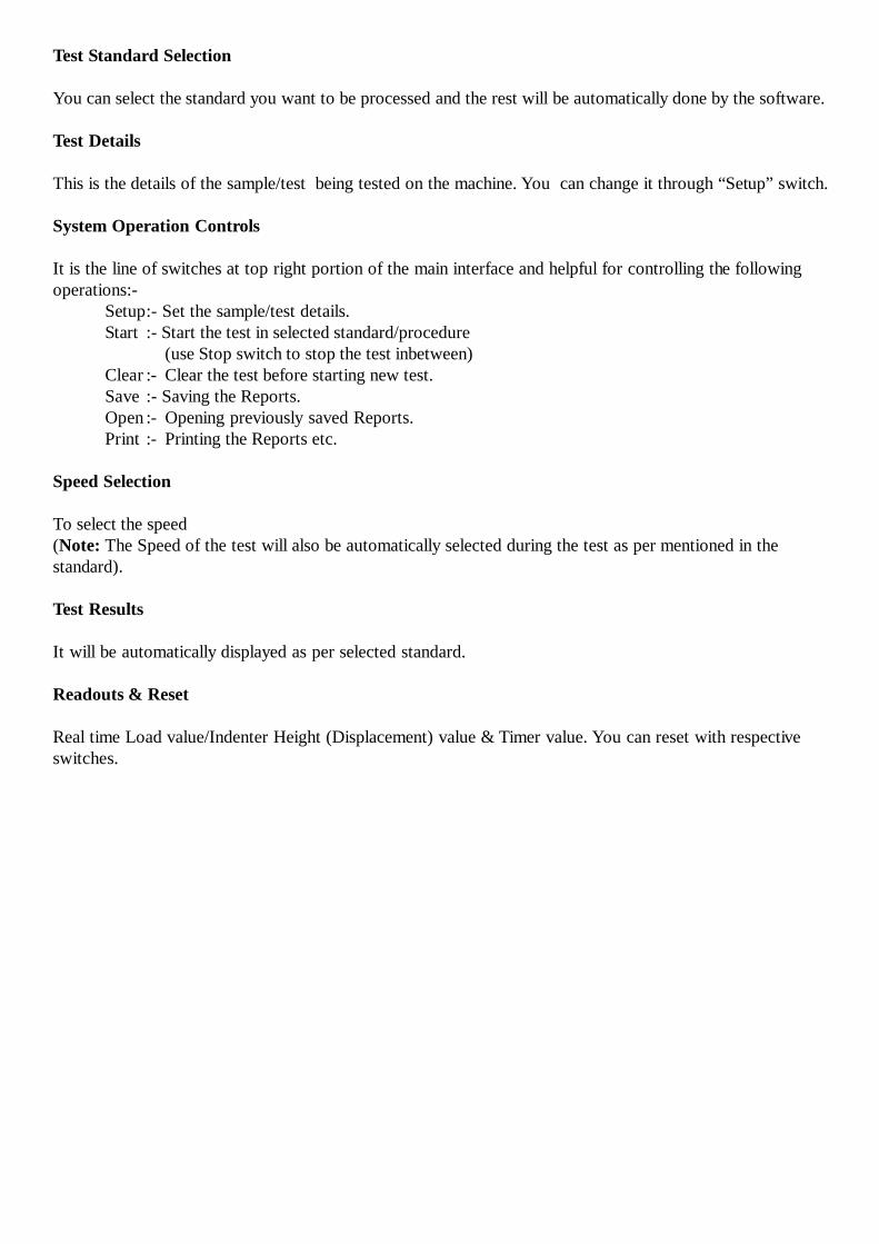
The main interface of the software is divided into eight parts as shown in figure no.4.1. Test Standard Selection2. Test Details.3. System Operation Controls.4. Speed Selection5. Test Results6. Readouts & Reset7. Device Status8. Device Control & Calibration
Figure No. 4
Test StandardSelection System Operation Controls
SpeedSelection
Device Controls &Calibration
Test Details
TestResults
Readouts & Resets Device Status
Test Standard Selection
You can select the standard you want to be processed and the rest will be automatically done by the software.
Test Details
This is the details of the sample/test being tested on the machine. You can change it through “Setup” switch.
System Operation Controls
It is the line of switches at top right portion of the main interface and helpful for controlling the followingoperations:-
Setup:- Set the sample/test details.Start :- Start the test in selected standard/procedure
(use Stop switch to stop the test inbetween)Clear :- Clear the test before starting new test.Save :- Saving the Reports.Open :- Opening previously saved Reports.Print :- Printing the Reports etc.
Speed Selection
To select the speed(Note: The Speed of the test will also be automatically selected during the test as per mentioned in thestandard).
Test Results
It will be automatically displayed as per selected standard.
Readouts & Reset
Real time Load value/Indenter Height (Displacement) value & Timer value. You can reset with respectiveswitches.
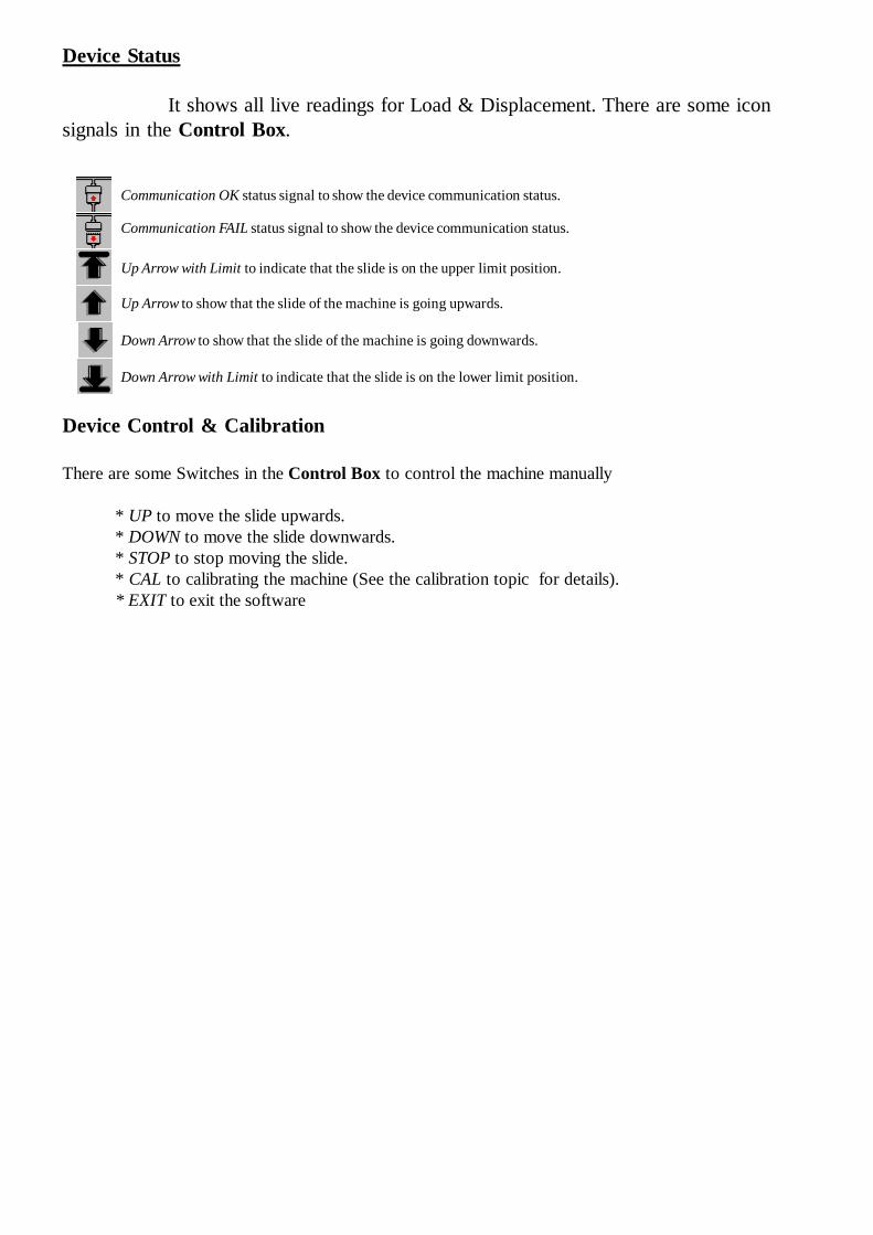
Device Status
It shows all live readings for Load & Displacement. There are some iconsignals in the Control Box.
Device Control & Calibration
There are some Switches in the Control Box to control the machine manually
* UP to move the slide upwards.* DOWN to move the slide downwards.* STOP to stop moving the slide.* CAL to calibrating the machine (See the calibration topic for details).* EXIT to exit the software
Communication OK status signal to show the device communication status.
Communication FAIL status signal to show the device communication status.
Up Arrow with Limit to indicate that the slide is on the upper limit position.
Up Arrow to show that the slide of the machine is going upwards.
Down Arrow to show that the slide of the machine is going downwards.
Down Arrow with Limit to indicate that the slide is on the lower limit position.

SWITCHES AT WINDOW
Reset Switches
There are two switches for reset:
1) Load : By clicking this load value of machine at any stage will be zero.2) Displacement : By clicking this “Indenter Height value” will be the distance between the platform
and Indenter at Upper limit position.
Note : To change the reset value you can use calibration window and simply change the ENC Resetvalue then Save calibration of displacement and close it
Control Switches
There are three switches for a manual controls:
1) Up : By clicking this Indenter goes to upwards.2) Stop : By cliking this both the outputs (O/P4 & O/P5) will be OFF3) Down : By clicking this Indenter goes to downwards.
Note :Your machine will be stop automatically at following conditions:
1) At Upper or Lower limit to avoid acciedent.2) At Over load condition.3) On completion of test
How to Calibrate the Device
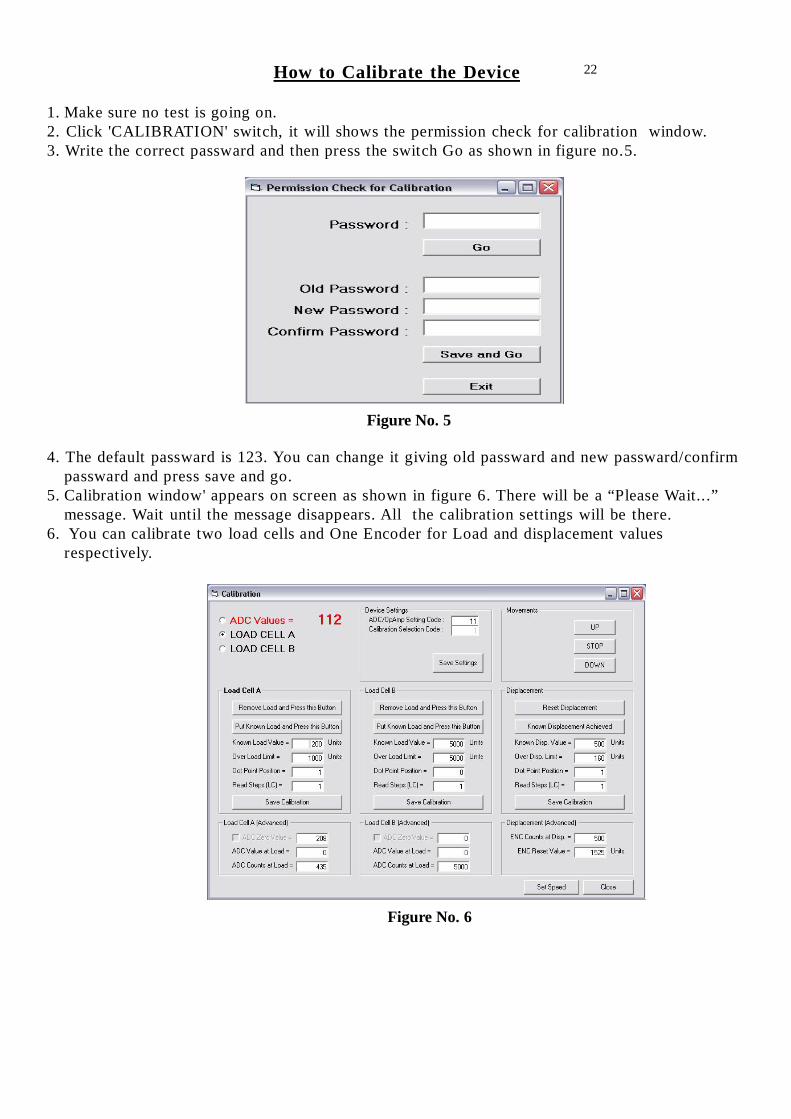
1. Make sure no test is going on.2. Click 'CALIBRATION' switch, it will shows the permission check for calibration window.3. Write the correct passward and then press the switch Go as shown in figure no.5.
4. The default passward is 123. You can change it giving old passward and new passward/confirmpassward and press save and go.
5. Calibration window' appears on screen as shown in figure 6. There will be a “Please Wait...”message. Wait until the message disappears. All the calibration settings will be there.
6. You can calibrate two load cells and One Encoder for Load and displacement valuesrespectively.
Figure No. 5
22
Figure No. 6

How to Calibrate the 'Load'
1. There are ADC Values giving you the direct readout of the Analog to Digital Converters Values(required to test the load cell). It varies according to the mV signal of the Load Cell. If youfind that these values decreas on increasing the load on the load cell Please swap the signalwires (s-/s+). Otherwise the device will not be calibrated.
2. Select the Load cell A/B. You can have two load cells of different capacity calibrated on thesame device. Use the same Load cell port and plug the load cell you want to calibrate thanselect Load Cell A to define it as the first load cell. Press “Save Settings” Switch.(ADC MODE = 11 (factory setting of the ADC Device)
3. Remove the load from the load cell and press “ Remove Load and Press this Button”swich. Now Put some known load and press “Put Known Load and Press this button” switch.
4. Write the known load values in units (10.0 Kg = 100 Units, 10.00 N = 1000 Units ie., justremove the decimal point)
5. Now write the Overload limit in units.6. Put the Dot Point Position 0 (for no dot point, or 1 for 0.0, 2 for 0.00)7. Put Least Count 1(for 1,2,3,...; 2 for 2,4,6,...; 5 for 5,10,15,.. etc.)8. Press 'Save Calibration' switch of Load Cell A to save the calibration of “A” Load Cell and
wait till the wait message disappears.9. Now switch of the device and remove the Load cell “A” socket from the device Load Cell Port.
Plug another Load Cell “B” of different capacity on the same Port and switch ON the device.10.Wait for atleast 30 seconds11. Select Load Cell “B” and press “Save Setting” Switch.12. Remove the load from the load cell and press “ Remove Load and Press this Button” swich.
Now Put some known load and press “Put Known Load and Press this button” switch.13. Write the known load values in units (10.0 Kg = 100 Units, 10.00 N = 1000 Units ie., just
remove the decimal point)14. Now write the Overload limit in units.15. Put the Dot Point Position 0 (for no dot point, or 1 for 0.0, 2 for 0.00)16. Put Least Count 1(for 1,2,3,...; 2 for 2,4,6,...; 5 for 5,10,15,.. etc.)17. Press 'Save Calibration' switch of Load Cell A to save the calibration of “A” Load Cell and
wait till the wait message disappears.18. Remove the load from the machine and click 'EXIT' button to exit from calibration setup.
Note : If you are using single Load Cell simply skip steps from 9-17.
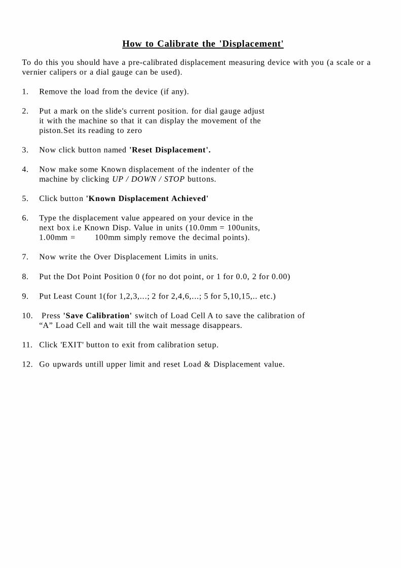
How to Calibrate the 'Displacement'
To do this you should have a pre-calibrated displacement measuring device with you (a scale or avernier calipers or a dial gauge can be used).
1. Remove the load from the device (if any).
2. Put a mark on the slide's current position. for dial gauge adjustit with the machine so that it can display the movement of thepiston.Set its reading to zero
3. Now click button named 'Reset Displacement'.
4. Now make some Known displacement of the indenter of themachine by clicking UP / DOWN / STOP buttons.
5. Click button 'Known Displacement Achieved'
6. Type the displacement value appeared on your device in thenext box i.e Known Disp. Value in units (10.0mm = 100units,1.00mm = 100mm simply remove the decimal points).
7. Now write the Over Displacement Limits in units.
8. Put the Dot Point Position 0 (for no dot point, or 1 for 0.0, 2 for 0.00)
9. Put Least Count 1(for 1,2,3,...; 2 for 2,4,6,...; 5 for 5,10,15,.. etc.)
10. Press 'Save Calibration' switch of Load Cell A to save the calibration of“A” Load Cell and wait till the wait message disappears.
11. Click 'EXIT' button to exit from calibration setup.
12. Go upwards untill upper limit and reset Load & Displacement value.
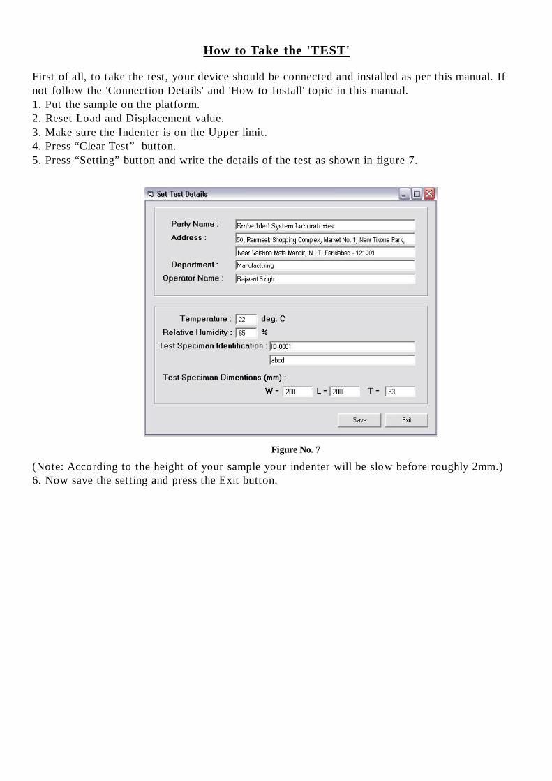
How to Take the 'TEST'
First of all, to take the test, your device should be connected and installed as per this manual. Ifnot follow the 'Connection Details' and 'How to Install' topic in this manual.1. Put the sample on the platform.2. Reset Load and Displacement value.3. Make sure the Indenter is on the Upper limit.4. Press “Clear Test” button.5. Press “Setting” button and write the details of the test as shown in figure 7.
(Note: According to the height of your sample your indenter will be slow before roughly 2mm.)6. Now save the setting and press the Exit button.
Figure No. 7

How to Save Report
If you want to save the report then click the SAVE switch.By clicking SAVE switch windows common con trol
save as dialog box will appear. Select the folder and type the name of the file you want to save your report as.
26
How to Open Report
If you want to open a previously saved report file you have to click the OPEN switch. By clicking OPEN
switch windows common control open dialog box will appear. Select the folder and the file you want to open. When
you open a file the Title Bar will display the name of that file and the Graph window will show the graph of the
report.
How to Print Report
To print the Report you have to click the PRINT switch. This action will open the windows common
control print dialog box. Follow the instruction and print the report.