Embed Size (px)
Citation preview

An ISO 9001:2008 Registered Company
InterMotive Inc.
12840 Earhart Ave. Auburn, CA 95602
Phone: (530) 823-1048
Fax: (530) 823-1516 Page 1 of 17
www.intermotive.net
[email protected] ECL554-A-061517-INS
Introduction
EcoLock is an automatic engine stop/start system that provides improved fuel economy, lower vehicle emis-sions, improved engine life, and extended oil changes by shutting off the engine when appropriate. When ena-bled by the driver (Transmission in Park), EcoLock allows an officer to remove the keys from the ignition, and leave the vehicle unattended, but with electrical loads left on (light bar, etc.). EcoLock continuously monitors battery voltages (OEM and aux battery if equipped), cabin and 2-way radio temperatures, while securing the vehicles shift lock, trunk/hatch and weapons rack. If battery voltages or temperatures move outside of a configurable range, EcoLock will automatically restart the engine, charging the battery and enabling AC/Heat as appropriate (regardless of the state of the controls). EcoLock will cycle the engine over time as needed to maintain battery voltages and/or cabin/radio tempera-tures. EcoLock will automatically shut off the engine if anyone attempts to steal the vehicle by shifting out of Park while the keys are removed (shifter remains locked in Park). EcoLock is instantly disabled when the keys are inserted and turned to Run. EcoLock can be used on K-9 units to maintain cabin temperatures in a preset range.
It is the installer’s responsibility to route and secure all wiring harnesses where they cannot be damaged by sharp objects, mechanical moving parts and high heat sources. Failure to do so could result in damage to the system or vehicle and create possible safety concerns for the operator and passengers. It is important to avoid placing the module where it could encounter strong magnetic fields from high current cabling connected to motors, solenoids, etc. Also avoid radio frequency energy from antenna’s or inverters next to the module. Finally, avoid high voltage spikes in vehicle wiring by always using diode clamped relays when installing upfitter circuits.
EcoLock ECL554 Module
Remove the dash end cap on the drivers side and mount the module as shown.
Ensure when routing harnesses that the tilt steering column does not contact them in the full down position. When installing the harnesses, leave several inches of take-out such that the module can be removed if necessary.
EcoLock™ ECL554-A Stop/Start Idle Reduction with Anti-Theft
2013—2015 Ford Interceptor (Sedan or Utility)
Installation Instructions
Disconnect vehicle battery before proceeding with installation

InterMotive Inc.
12840 Earhart Ave. Auburn, CA 95602
Phone: (530) 823-1048
Fax: (530) 823-1516 Page 2 of 17
www.intermotive.net
[email protected] ECL554-A-061517-INS
Installation Instructions (continued)
Ignition Switch Harness
The ignition switch must be accessed in order to connect the EcoLock ignition harness. The following sec-tions provide separate ignition switch harness installation instructions for the Sedan and Utility Interceptors. Several dash trim panels must be removed. See appropriate section for your installation.
Data Link Harness
1. Locate the vehicle’s OBDII Data Link Connector. It will be mounted below the lower left dash panel.
2. Remove the mounting screws for the OBDII connector. Plug the Red connector from the EcoLock Data Link Harness into the vehicle’s OBDII connector. Ensure the connection is fully seated and secure with the supplied wire tie.
3. Mount the Black pass through connector from the EcoLock Data Link Harness in the former location of the vehicle’s OBDII connector.
4. Secure the EcoLock Data Link harness so that it does not hang below the lower dash panel.
5. Plug the free end of the Data Link harness into the mating 6-pin connector on the EcoLock module.
Data Link Harness
plugs in here
• Remove the instrument panel face trim by removing
one screw, firmly grasping the panel, and pulling it towards the rear of the vehicle.
• Not shown—Remove the lower left dash panel under
the steering column.
• Remove the lower center instrument panel by firmly
grasping the panel and pulling toward the rear of the vehicle.
Sedan Interceptor
InterMotive Inc.
12840 Earhart Ave. Auburn, CA 95602
Phone: (530) 823-1048
Fax: (530) 823-1516 Page 3 of 17
www.intermotive.net
[email protected] ECL554-A-061517-INS
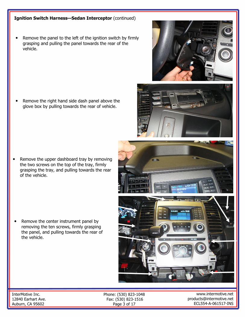
Ignition Switch Harness—Sedan Interceptor (continued)
• Remove the center instrument panel by
removing the ten screws, firmly grasping the panel, and pulling towards the rear of the vehicle.
• Remove the upper dashboard tray by removing
the two screws on the top of the tray, firmly grasping the tray, and pulling towards the rear of the vehicle.
• Remove the panel to the left of the ignition switch by firmly
grasping and pulling the panel towards the rear of the vehicle.
• Remove the right hand side dash panel above the
glove box by pulling towards the rear of vehicle.

InterMotive Inc.
12840 Earhart Ave. Auburn, CA 95602
Phone: (530) 823-1048
Fax: (530) 823-1516 Page 4 of 17
www.intermotive.net
[email protected] ECL554-A-061517-INS
• Remove the ignition switch by removing the
three screws and pulling the switch out of the opening.
• Remove the OEM 7 pin connector from the
ignition switch and connect it to the female connector of the EcoLock harness. Connect the male EcoLock connector to the OEM igni-tion switch.
Ignition Switch Harness—Sedan Interceptor (continued)
InterMotive Inc.
12840 Earhart Ave. Auburn, CA 95602
Phone: (530) 823-1048
Fax: (530) 823-1516 Page 5 of 17
www.intermotive.net
[email protected] ECL554-A-061517-INS
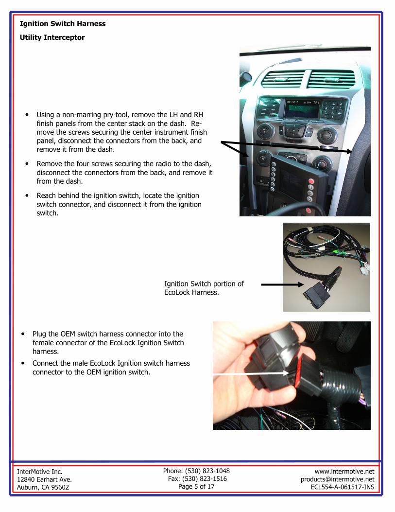
Ignition Switch Harness
Utility Interceptor
• Using a non-marring pry tool, remove the LH and RH
finish panels from the center stack on the dash. Re-move the screws securing the center instrument finish panel, disconnect the connectors from the back, and remove it from the dash.
• Remove the four screws securing the radio to the dash,
disconnect the connectors from the back, and remove it from the dash.
• Reach behind the ignition switch, locate the ignition
switch connector, and disconnect it from the ignition switch.
• Plug the OEM switch harness connector into the
female connector of the EcoLock Ignition Switch harness.
• Connect the male EcoLock Ignition switch harness
connector to the OEM ignition switch.
Ignition Switch portion of EcoLock Harness.
InterMotive Inc.
12840 Earhart Ave. Auburn, CA 95602
Phone: (530) 823-1048
Fax: (530) 823-1516 Page 6 of 17
www.intermotive.net
[email protected] ECL554-A-061517-INS
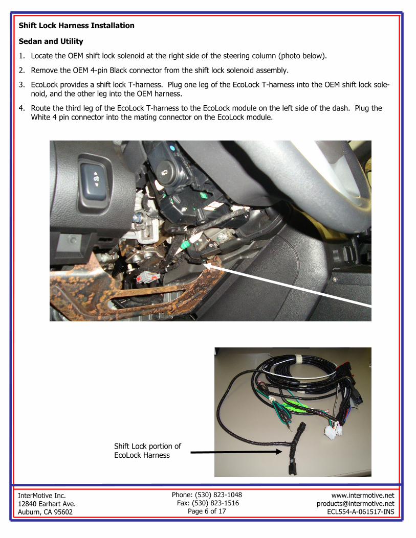
Shift Lock Harness Installation
Sedan and Utility
1. Locate the OEM shift lock solenoid at the right side of the steering column (photo below).
2. Remove the OEM 4-pin Black connector from the shift lock solenoid assembly.
3. EcoLock provides a shift lock T-harness. Plug one leg of the EcoLock T-harness into the OEM shift lock sole-noid, and the other leg into the OEM harness.
4. Route the third leg of the EcoLock T-harness to the EcoLock module on the left side of the dash. Plug the White 4 pin connector into the mating connector on the EcoLock module.
Shift Lock portion of EcoLock Harness

InterMotive Inc.
12840 Earhart Ave. Auburn, CA 95602
Phone: (530) 823-1048
Fax: (530) 823-1516 Page 7 of 17
www.intermotive.net
[email protected] ECL554-A-061517-INS
Police Run/Start Relay
Sedan and Utility
Special relay with Tan wire for Po-
lice Run/Start Relay replacement in BJB, provided in kit.
1. The Battery Junction Box (BJB) is located under the hood on the driv-ers side. Remove the cover and re-move the OEM Police Run/Start Re-lay and replace it with the relay with the Tan wire, supplied in the Eco Lock kit (picture above).
2. The relay’s Tan wire mates with a similar Tan wire (bullet connector) from the EcoLock module. Starting at the module, route the Tan wire (Pin 1 of the 12 pin connector) at the EcoLock module through the bulkhead into the engine compart-ment (If needed, see instructions for pass through wiring at www.intermotive.net).
3. Release the clips on the sides of the BJB which hold it in place and lift it up to allow routing the Tan wire underneath the BJB. Bring the Tan wire up on the side of the BJB closest to the cab, and into the BJB (as show in picture at right). Plug the two halves of the bullet connector together, route the wire inside the BJB as shown, and cable tie the wire to the post in BJB.

InterMotive Inc.
12840 Earhart Ave. Auburn, CA 95602
Phone: (530) 823-1048
Fax: (530) 823-1516 Page 8 of 17
www.intermotive.net
[email protected] ECL554-A-061517-INS
I/O Wiring, Features, and Descriptions: (Solder and heat shrink all connections)
Lock Output
Pin 2, White wire of the 12 pin connector is the EcoLock output. This output (500mA max current) can control installer supplied normally closed relays to disable the trunk and weapon rack release buttons when EcoLock is active. When EcoLock activates this output, the relays will open the circuits from the buttons and disable them. This minimizes possible theft when Eco-Lock is active and the vehicle is unattended.
When EcoLock is enabled, this output becomes active after a configurable delay (default 10 seconds). This output remains active until the key is back in the run position.
EcoLock Enable Input
Pin 10 Gray wire of the 12 pin connector is the EcoLock system enable. This input can be connected to an installer supplied momentary switch or to another signal (control head, or steering wheel switch, etc.) that will automatically enable EcoLock. An “EcoLock Enable” label is included in the kit to identify the enable switch. By default, this enable input is high true (12V). A programming sequence can be used to toggle this input between High and Low true (gnd). The following steps detail the procedure:
With the key in Run, engine off and transmission in Park
1. Ground the TEST pad on the module
2. Shift to Reverse
3. Press and release the Service Brake 5 times in approximately 10 seconds
Onboard LED 7 will flash to indicate that the programming sequence was successful. If the LED flashes 3 times, the input is now High True. If the LED flashes 6 times, the input is now Low True. If the LED did not flash, shift back to Park, wait 15 seconds and attempt the sequence again. Call InterMotive Technical Support for further assistance.
Aux Battery Input (up to 36 Volt)
The EcoLock module internally monitors the OEM battery voltage. A second auxiliary battery may also be monitored. Pin #4 (Gray with Black stripe wire) of the 12 Pin Connector is an auxiliary battery voltage moni-tor input. It measures the analog battery input and can trigger a low battery restart when this input falls be-low a user defined level. Extend the Gray/Black wire as needed and connect to aux battery. By default, this trigger is disabled, but may be enabled using the free EcoLock software application. Contact InterMotive for details.
Police Interceptor Sedan Trunk Release Circuit
The trunk release circuit is pin 4 Brown-Yellow wire in BCM (behind Park Brake) connector 2280C. Use a nor-mally closed relay controlled by the Lock Output to in-terrupt & disable the trunk release switch.
Police Interceptor Utility Lift Gate Release Circuit
The lift gate release circuit is pin 23 Brown wire in BCM (behind Park Brake) connector 2280C. Use a nor-mally closed relay controlled by the Lock Output to in-terrupt & disable the lift gate release switch.
2280C Connector Face
2280C Connector Face

InterMotive Inc.
12840 Earhart Ave. Auburn, CA 95602
Phone: (530) 823-1048
Fax: (530) 823-1516 Page 9 of 17
www.intermotive.net
[email protected] ECL554-A-061517-INS
EcoLock Active LED
An LED is provided in the kit which lights when EcoLock is active.
1. Drill a 12mm (0.492”) hole in the desired mounting location. One possibility is the dash panel to the left of the Steering Wheel (see picture below).
2. Route the LED harness through the hole and mount the LED in the hole.
3. Slide the LED’s lock nut onto the harness and snug it down onto the back of the LED.
4. Plug in the 4 pin (Black) connector of the LED harness into the EcoLock module.
5. Apply optional “EcoLock Active” label included in the kit.
Restart Beeper
When active, EcoLock will periodically stop and start the en-gine. Pin #3 Orange wire (inside split loom) of the 12 Pin Con-nector drives a warning beeper that will sound for 2 seconds
prior to an auto restart. The bezel on the beeper can be ro-tated to control volume.
• Attach the beeper using zip ties in the location shown in the picture (below where the module will be installed).
• Connect the Orange lead to the Red post of beeper, and Black lead to the negative post.
• The Black lead eyelet must be grounded in order for the beeper to function. Attach the eyelet to the location in the photo.

InterMotive Inc.
12840 Earhart Ave. Auburn, CA 95602
Phone: (530) 823-1048
ax: (530) 823-1516 Page 10 of 17
www.intermotive.net
[email protected] ECL554-A-061517-INS
Thermostat/Thermistor
The thermistor option may be used to auto restart the engine as a result of hot or cold temperatures. It may be used to prevent the cabin or the engine from getting too cold or too hot in severe environments. It may also be used in po-lice K9 vehicles to prevent cabin temperature extremes.
1. Mount the thermistor, pin #5 (12 pin connector, Green wire) in a location where it cannot be damaged by sharp objects and mechanical moving parts such as the Park Brake or tilt steering wheel mechanisms.
2. Attach the thermistor Ground eyelet to the location in the photo.
Low Temperature Thermostat Engine Cycling
ECL554 will turn the cabin heater on high when low temperature auto-restart occurs. If the cabin temperature does not increase 3 degrees in 6 minutes af-ter a low temperature restart, the thermostat is disabled until the key is cycled.
High Temperature Thermostat Engine Cycling
ECL554 will turn the cabin air conditioner on the max A/C setting when a high temperature auto-restart occurs. If the cabin temperature does not decrease 3 degrees in 6 minutes after a high temperature restart, the ther-mostat is disabled until the key is cycled.
-Q Option - Bimetal 2-way Radio/Equipment Protection Thermostat
A Bimetallic thermostat switch and 15’ harness is included in this optional kit which will close when its tempera-
ture reaches 150° F. This is connected to pin #5 (12 pin connector, Green wire with White stripe), which will trig-
ger an engine restart and ECL554 will turn the cabin air conditioner on max. Once the thermostat switch contacts
open again (135° F), the air conditioner will turn off and the engine will shutdown (all other conditions met). The
Thermostat can be screwed or thermal epoxied to a 2-way radio’s case, or other equipment.
Thermostat switch harness connects
here.
2-Way Radio/Equipment Ther-
mostat 15’ Harness
Thermostat switch. Attach with
screws or thermal epoxy to equip-ment being monitored for tempera-
ture.
InterMotive Inc.
12840 Earhart Ave. Auburn, CA 95602
Phone: (530) 823-1048
Fax: (530) 823-1516 Page 11 of 17
www.intermotive.net
[email protected] ECL554-A-061517-INS
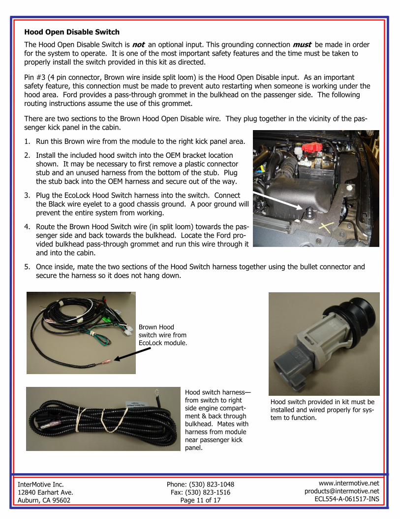
Hood Open Disable Switch
The Hood Open Disable Switch is not an optional input. This grounding connection must be made in order for the system to operate. It is one of the most important safety features and the time must be taken to properly install the switch provided in this kit as directed.
Pin #3 (4 pin connector, Brown wire inside split loom) is the Hood Open Disable input. As an important safety feature, this connection must be made to prevent auto restarting when someone is working under the hood area. Ford provides a pass-through grommet in the bulkhead on the passenger side. The following routing instructions assume the use of this grommet.
There are two sections to the Brown Hood Open Disable wire. They plug together in the vicinity of the pas-senger kick panel in the cabin.
1. Run this Brown wire from the module to the right kick panel area.
2. Install the included hood switch into the OEM bracket location shown. It may be necessary to first remove a plastic connector stub and an unused harness from the bottom of the stub. Plug the stub back into the OEM harness and secure out of the way.
3. Plug the EcoLock Hood Switch harness into the switch. Connect the Black wire eyelet to a good chassis ground. A poor ground will prevent the entire system from working.
4. Route the Brown Hood Switch wire (in split loom) towards the pas-senger side and back towards the bulkhead. Locate the Ford pro-vided bulkhead pass-through grommet and run this wire through it and into the cabin.
5. Once inside, mate the two sections of the Hood Switch harness together using the bullet connector and secure the harness so it does not hang down.
Hood switch provided in kit must be
installed and wired properly for sys-tem to function.
Hood switch harness—
from switch to right side engine compart-
ment & back through bulkhead. Mates with
harness from module
near passenger kick panel.
Brown Hood
switch wire from EcoLock module.

InterMotive Inc.
12840 Earhart Ave. Auburn, CA 95602
Phone: (530) 823-1048
Fax: (530) 823-1516 Page 12 of 17
www.intermotive.net
[email protected] ECL554-A-061517-INS
Configurable options (with default settings)
• Battery restart, recharge, and delay values:
∗ Restart Voltage = 11.8V
∗ Restart Delay (the battery Voltage must be below the threshold for this period of time before a low battery auto-restart) = 5 Seconds
∗ Recharge Voltage = 13.5V (engine runs until this voltage is reached, then the Recharge Timer starts (see below).
∗ Recharge Timer = 60 Seconds (engine continues to run after reaching Recharge Voltage for this length of time).
• Secondary battery restart, recharge, and delay values (disabled by default).
• EcoLock enable settings (this input activates the system— usually a switch controls this).
∗ EcoLock enable sense = High true
∗ EcoLock enable delay = 3 seconds (key must be removed within 3 seconds after pushing enable button)
• EcoLock timer duration (this timer is for vehicle lock-down, gun rack and trunk) = 10 Seconds
• Idle shutoff timer duration (after driver shuts key off, engine shuts down) = 2 Seconds
• Enable/disable idle shutoff timer = Enabled
• Minimum engine temperature for auto-shutoff to occur = -40° F
• Operation of the Brake pedal = Auto-restart
• Thermostat settings:
∗ Enable/Disable thermostat = Enabled
∗ Low restart temperature = 40° F
∗ High restart temperature = 85° F
∗ Warm-up temperature = 55° F (after a low temperature restart, engine will not shut off until cabin tem-perature exceeds this).
∗ Cool-down temperature = 75° F (after a high temperature restart, engine will not shut off until cabin cools to this value).
Reconnect the vehicle battery
ECL554 Module Mounting
Ensure all harnesses are properly connected and routed, and are not hanging below the dash area. Mount the module as described on page one and secure with supplied screws or double sided tape.
ECL554 Harness (4 Pin connector and 12 Pin connector)
1. Plug the ECL554 12 Pin connector into the mating 12 pin connector on the ECL554 module.
2. Plug the ECL554 4 Pin connector into the mating 4 pin connector on the ECL554 module.

InterMotive Inc.
12840 Earhart Ave. Auburn, CA 95602
Phone: (530) 823-1048
Fax: (530) 823-1516 Page 13 of 17
www.intermotive.net
[email protected] ECL554-A-061517-INS
Computer Installation
1. Ensure the proper driver is installed for the USB to Serial download cable. This driver can be found at: http://www.ftdichip.com/Drivers/VCP.htm
2. To install the programming utility, unzip the ECL554 Pro-gramming Utility folder to your local hard drive.
3. Create a shortcut on the desktop if necessary, but do not sep-arate the ECL554 Programming Utility.exe file from the rxtx-Serial.dll file!
4. Plug in the USB cable (Part# s-h37a1) prior to starting the ap-plication.
5. Double click the ECL554 Programming Utility.exe file to launch.
6. This screen will come up.
If the program does not launch, close all applications and re-install the Java Runtime Environment and the ECL554 Pro-gramming Utility.
All options in the configuration menu come with descriptions that explain what parameters are currently set and how to update them.
7. Configure the settings as desired.
8. Select “Save Configuration” under the “File” tab.
9. Enter a configuration name (Max. 16 characters) and click “OK”.
ECL554 Programming Utility Instructions
The EcoLock Programming Utility allows the operation of the system to be customized by modifying the configu-rable options on the previous page, and to optimize it for your particular application.
Requirements
• Java Runtime Environment (v1.6.0_18 or later [32 bit]) must be installed on your computer prior to run-ning this utility. Most PC’s already have Java installed. The most recent version can be obtained for free at http://java.com/en/download/manual.jsp.
• The ECL554 Programming Utility. This is a free Intermotive software program that will need to be loaded on your PC. The files are available from the download page at www.intermotive.net. It is recommended that an “InterMotive” folder be created to store the files.
• USB to Serial cable (part# s-h37a1) is included with the a-IPU kit and is a one-time purchase. This kit is required for all programming and includes a power adapter for desk use.
Once ECL554 Programming Utility has been run and the specific configuration has been created, it can be downloaded onto the ECL554 module(s) with the Programming Utility.
InterMotive Inc.
12840 Earhart Ave. Auburn, CA 95602
Phone: (530) 823-1048
Fax: (530) 823-1516 Page 14 of 17
www.intermotive.net
[email protected] ECL554-A-061517-INS
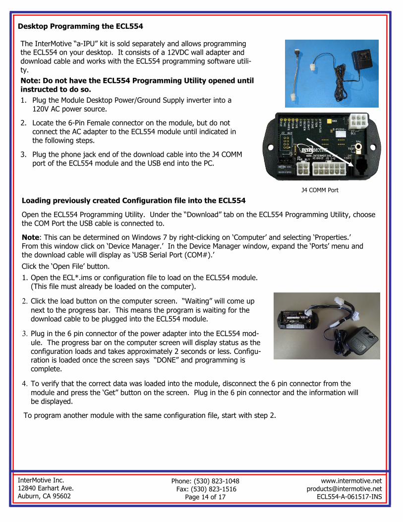
Desktop Programming the ECL554
The InterMotive “a-IPU” kit is sold separately and allows programming the ECL554 on your desktop. It consists of a 12VDC wall adapter and download cable and works with the ECL554 programming software utili-ty.
Note: Do not have the ECL554 Programming Utility opened until instructed to do so.
1. Plug the Module Desktop Power/Ground Supply inverter into a 120V AC power source.
2. Locate the 6-Pin Female connector on the module, but do not connect the AC adapter to the ECL554 module until indicated in the following steps.
3. Plug the phone jack end of the download cable into the J4 COMM port of the ECL554 module and the USB end into the PC.
J4 COMM Port
Loading previously created Configuration file into the ECL554
Open the ECL554 Programming Utility. Under the “Download” tab on the ECL554 Programming Utility, choose the COM Port the USB cable is connected to.
Note: This can be determined on Windows 7 by right-clicking on ‘Computer’ and selecting ‘Properties.’ From this window click on ‘Device Manager.’ In the Device Manager window, expand the ‘Ports’ menu and the download cable will display as ‘USB Serial Port (COM#).’
Click the ‘Open File’ button.
1. Open the ECL*.ims or configuration file to load on the ECL554 module. (This file must already be loaded on the computer).
2. Click the load button on the computer screen. “Waiting” will come up
next to the progress bar. This means the program is waiting for the download cable to be plugged into the ECL554 module.
3. Plug in the 6 pin connector of the power adapter into the ECL554 mod-
ule. The progress bar on the computer screen will display status as the configuration loads and takes approximately 2 seconds or less. Configu-ration is loaded once the screen says “DONE” and programming is complete.
4. To verify that the correct data was loaded into the module, disconnect the 6 pin connector from the
module and press the ‘Get” button on the screen. Plug in the 6 pin connector and the information will be displayed.
To program another module with the same configuration file, start with step 2.
InterMotive Inc.
12840 Earhart Ave. Auburn, CA 95602
Phone: (530) 823-1048
Fax: (530) 823-1516 Page 15 of 17
www.intermotive.net
[email protected] ECL554-A-061517-INS
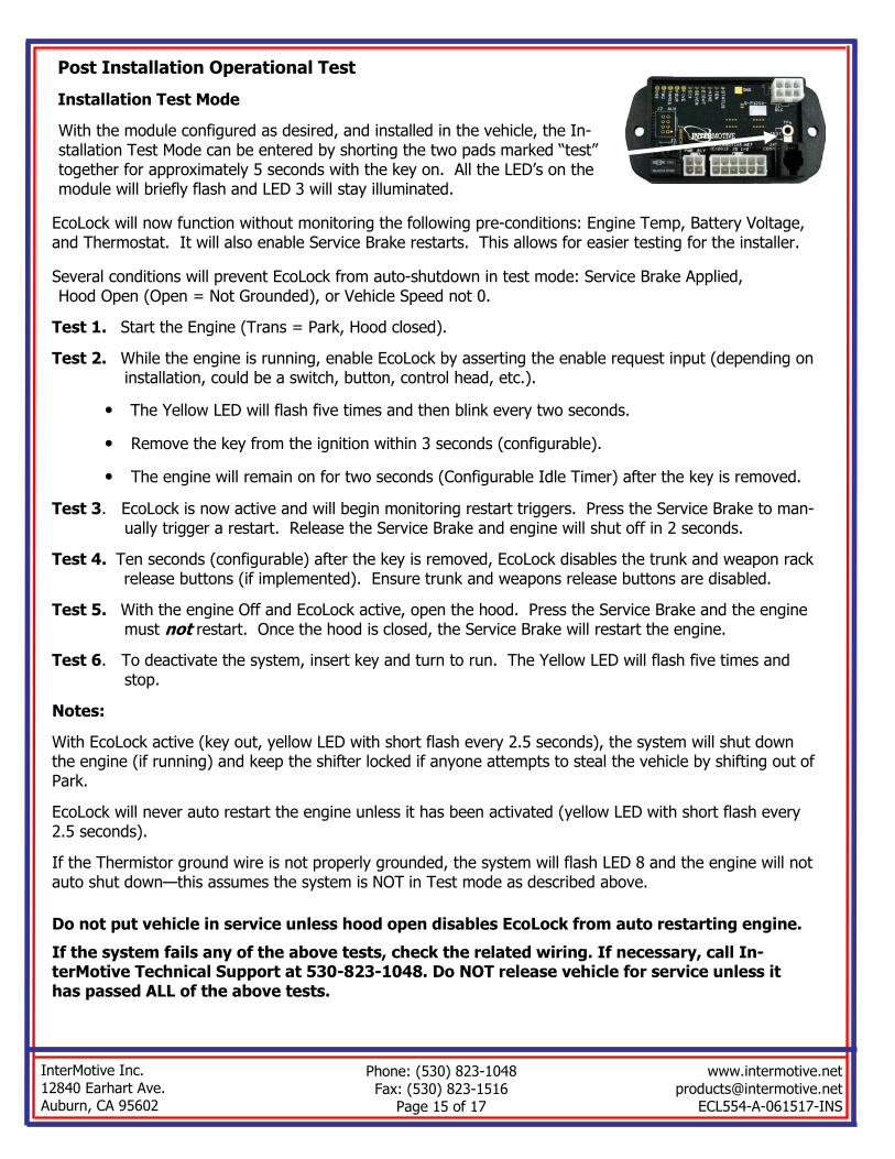
Post Installation Operational Test
Installation Test Mode
With the module configured as desired, and installed in the vehicle, the In-stallation Test Mode can be entered by shorting the two pads marked “test” together for approximately 5 seconds with the key on. All the LED’s on the module will briefly flash and LED 3 will stay illuminated.
EcoLock will now function without monitoring the following pre-conditions: Engine Temp, Battery Voltage, and Thermostat. It will also enable Service Brake restarts. This allows for easier testing for the installer.
Several conditions will prevent EcoLock from auto-shutdown in test mode: Service Brake Applied, Hood Open (Open = Not Grounded), or Vehicle Speed not 0.
Test 1. Start the Engine (Trans = Park, Hood closed).
Test 2. While the engine is running, enable EcoLock by asserting the enable request input (depending on installation, could be a switch, button, control head, etc.).
• The Yellow LED will flash five times and then blink every two seconds.
• Remove the key from the ignition within 3 seconds (configurable).
• The engine will remain on for two seconds (Configurable Idle Timer) after the key is removed.
Test 3. EcoLock is now active and will begin monitoring restart triggers. Press the Service Brake to man-ually trigger a restart. Release the Service Brake and engine will shut off in 2 seconds.
Test 4. Ten seconds (configurable) after the key is removed, EcoLock disables the trunk and weapon rack release buttons (if implemented). Ensure trunk and weapons release buttons are disabled.
Test 5. With the engine Off and EcoLock active, open the hood. Press the Service Brake and the engine must not restart. Once the hood is closed, the Service Brake will restart the engine.
Test 6. To deactivate the system, insert key and turn to run. The Yellow LED will flash five times and stop.
Notes:
With EcoLock active (key out, yellow LED with short flash every 2.5 seconds), the system will shut down the engine (if running) and keep the shifter locked if anyone attempts to steal the vehicle by shifting out of Park.
EcoLock will never auto restart the engine unless it has been activated (yellow LED with short flash every 2.5 seconds).
If the Thermistor ground wire is not properly grounded, the system will flash LED 8 and the engine will not auto shut down—this assumes the system is NOT in Test mode as described above.
Do not put vehicle in service unless hood open disables EcoLock from auto restarting engine.
If the system fails any of the above tests, check the related wiring. If necessary, call In-terMotive Technical Support at 530-823-1048. Do NOT release vehicle for service unless it has passed ALL of the above tests.

An ISO 9001:2008 Registered Company
InterMotive Inc.
12840 Earhart Ave. Auburn, CA 95602
Phone: (530) 823-1048
Fax: (530) 823-1516 Page 16 of 17
www.intermotive.net
[email protected] ECL554-A-061517-INS
Leave in Vehicle Operating Instructions
EcoLock™ ECL554-A Stop/Start Idle Reduction with Anti-Theft 2013—2015 Ford Interceptor (Sedan or Utility)
The EcoLock ECL554 provides enhanced fuel economy and lower vehicle emissions by eliminating unnecessary idle time. Once activated by pushing the button and removing the key, the engine shuts down, and locks the shifter. Auto engine restarts are triggered by low battery voltage, cabin/radio temperatures (if enabled), or holding the Service Brake on. The system allows a vehicle to be left unattended with various equipment left on (light bar, radio’s, etc.), and will cycle the engine to prevent the batteries from being discharged, or cabin tem-peratures from exceeding preset limits. The trunk switch and weapons rack release buttons are disabled at this time. The system also provides anti-theft capabilities described below.
• EcoLock is enabled by removing the key from the ignition within 3 seconds of pushing the EcoLock enable
button. Transmission must be in Park and Service Brake not pushed.
• When activated, the engine will shut down two seconds (settable) after the key is removed. Note that the
Service Brake will prevent engine shutoff. ECL554 locks the shifter in Park while active.
• Once the engine has been auto-stopped (ECL554 active) the system monitors the main battery voltage, in
addition to an optional auxiliary battery (possibly in trunk). If either battery falls below a minimum value, the system will sound an alarm for 2 seconds and auto-restart the engine to recharge the batteries. After a pre-set charging time, the engine will shut off again.
• The driver may reenter the vehicle and press/hold the Service Brake to run the heater or A/C without disa-
bling EcoLock. Releasing Service Brake will allow the engine to shut down (assuming the engine off condi-tions are met).
• To prevent unattended vehicle theft (EcoLock active), the engine will turn off if someone attempts to
shift the vehicle out of Park. The shifter will remain locked, and the trunk and weapons rack release but-tons will remain disabled.
• Inserting the key and turning it to Run restores normal operation. Weapons release buttons and truck
release are restored to normal operation.
ECOLock Active Transmission in Park
Hood Closed Service Brake Not Applied
Battery Voltage > 11.8V
(settable)
Cabin Temperature in Normal
Range
Default requirements for auto engine shut off
ECOLock Active Transmission in Park
Hood Closed Engine Auto-stopped
Default requirements for auto engine restart
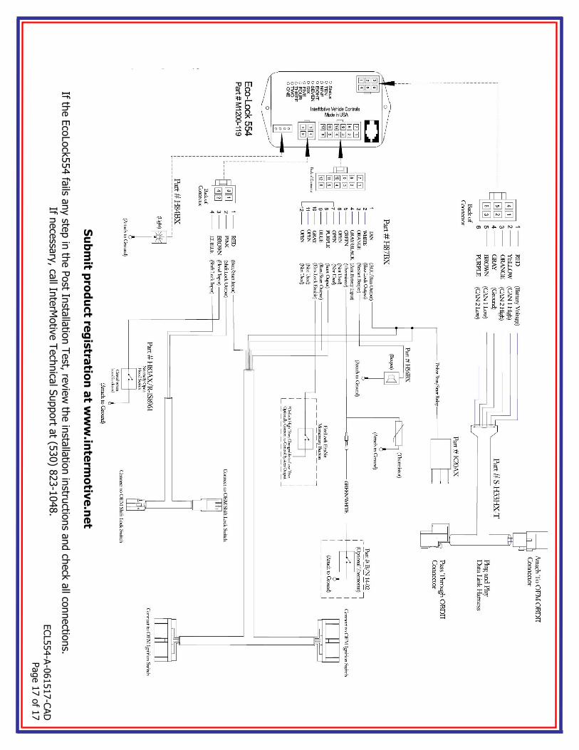
ECL554-A-061517-CAD
Page 17 of 1
7
Submit p
roduct re
gistra
tion at w
ww.interm
otiv
e.net
If the EcoLock554 fa
ils any ste
p in th
e Post In
stallatio
n Test, re
view th
e in
stallatio
n in
structio
ns a
nd ch
eck all co
nnectio
ns.
If necessa
ry, ca
ll InterM
otive Technica
l Support a
t (530) 8
23-1048.