Embed Size (px)
Citation preview
an ISO 9001:2015 Registered Company
18865 Goll St. San Antonio, TX 78266 Phone: 800-862-6658
Sales: [email protected] Support: [email protected]
www.vintageair.com
909120 REV B 03/26/18, PG 1 OF 7
2
www.vintageair.com
909120 REV B 03/26/18, PG 2 OF 7
Cover..................................................................................................................................Table of Contents.................................................................................................................Installation Instructions.........................................................................................................Operation of Controls............................................................................................................Wiring Diagram Heat/Cool.....................................................................................................Wiring Diagram Heat/Cool/Defrost..........................................................................................Air Conditioning Adjustments.................................................................................................
1 2 3 4 5 6 7
Table of Contents
3
www.vintageair.com
909120 REV B 03/26/18, PG 3 OF 7
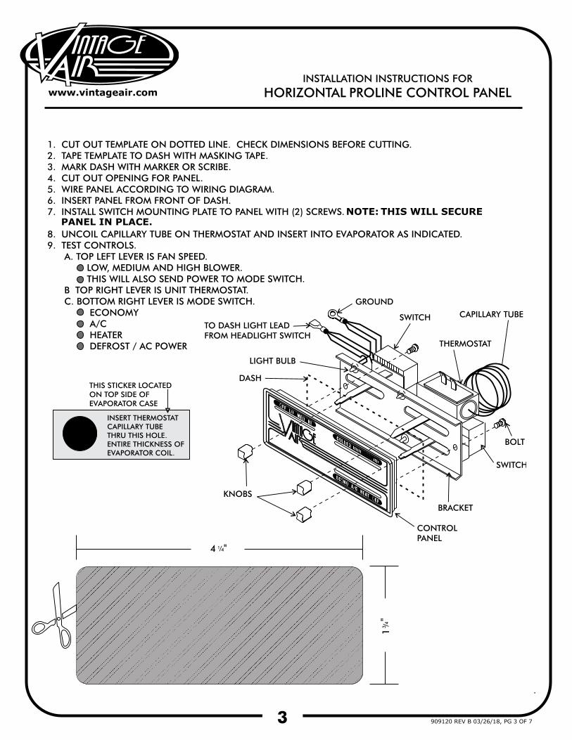
NOTE:PANEL IN PLACE.
THIS WILL SECURE

4
www.vintageair.com
909120 REV B 03/26/18, PG 4 OF 7
5
www.vintageair.com
909120 REV B 03/26/18, PG 5 OF 7
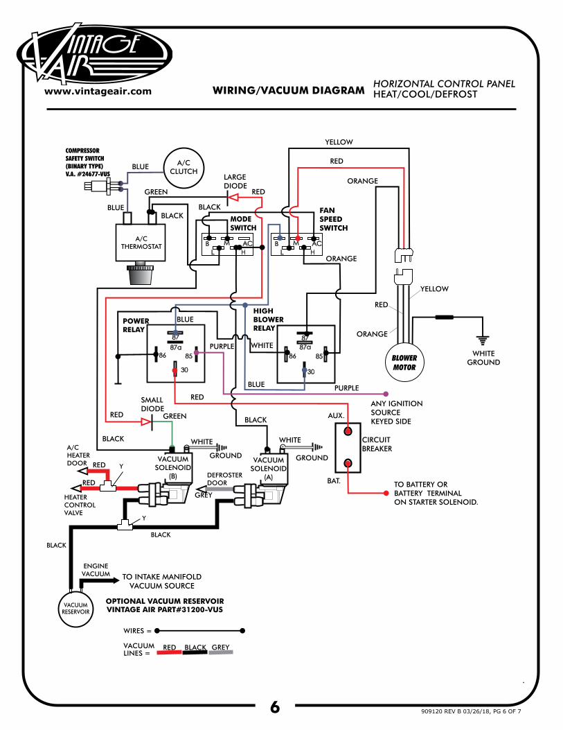
6
www.vintageair.com
909120 REV B 03/26/18, PG 6 OF 7
7
www.vintageair.com
909120 REV B 03/26/18, PG 7 OF 7
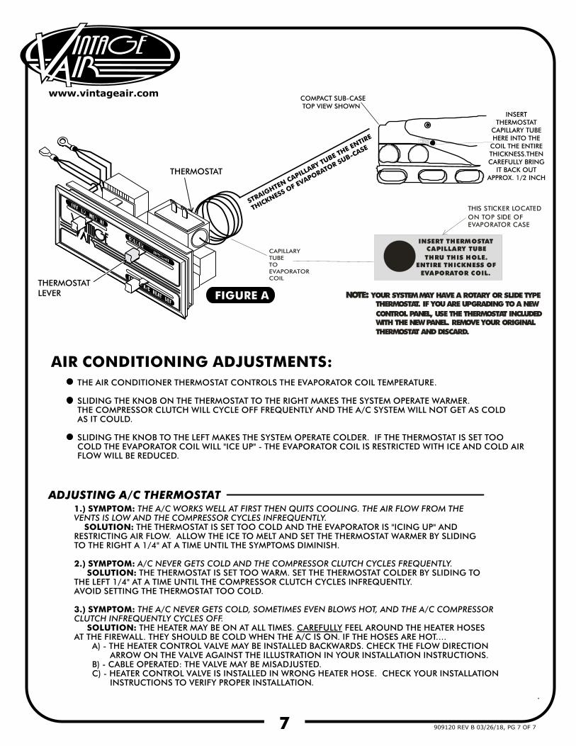
INSERT THERMOSTATCAPILLARY TUBETHRU THIS HOLE.
ENTIRE THICKNESS OFEVAPORATOR COIL.
THIS STICKER LOCATED ON TOP SIDE OF EVAPORATOR CASE
NOTE: YOUR SYSTEM MAY HAVE A ROTARY OR SLIDE TYPE THERMOSTAT. IF YOU ARE UPGRADING TO A NEW CONTROL PANEL, USE THE THERMOSTAT INCLUDED WITH THE NEW PANEL. REMOVE YOUR ORIGINAL THERMOSTAT AND DISCARD.
INSERT THERMOSTATCAPILLARY TUBE THRU THIS HOLE THE
ENTIRE THICKNESS OFEVAPORATOR COIL.
INSERT THERMOSTAT
CAPILLARY TUBE HERE INTO THE
COIL THE ENTIRE THICKNESS.THEN CAREFULLY BRING
IT BACK OUTAPPROX. 1/2 INCH
COMPACT SUB-CASE TOP VIEW SHOWN
CAPILLARYTUBETOEVAPORATORCOIL
STRAIGHTEN CAPILLARY TUBE THE ENTIRE
THICKNESS OF EVAPORATOR SUB-CASE