Embed Size (px)
Citation preview
Progress In Electromagnetics Research Letters, Vol. 52, 1–9, 2015
An Open-Sleeve Folded U-Shaped Multiband Antenna
Elodie Georget1, 2, *, Redha Abdeddaim1, Franck Garde3, and Pierre Sabouroux1
Abstract—In this paper, a multiband flexible antenna is presented. This antenna was realized on aflexible substrate in order to realize a deployable system for a distress beacon. We used the conceptof open-sleeve antenna to change a quadrupole mode into a dipole mode. The main radiating elementof the antenna is a dual-band folded U-shaped antenna. The operating frequencies of this antenna arestudied depending on the length of the parasitic elements. In order to understand the matching and theradiation patterns in far field of both antennas (U-shaped and open-sleeve), their magnetic behaviorsin near field are studied in simulation and in measurement. The simulated and measured radiationpatterns are also presented to check the study in near field.
1. INTRODUCTION
The objective of the BELOCOPA project is the development of an autonomous, embedded andremovable beacon to localize and collect the data of a crashed plane in sea. Our objective was torealize a deployable multiband antenna for this distress beacon. This antenna has to be flexible and hasto radiate dipole modes at three resonance frequencies in the UHF band.
These last years, a lot of radio-communication embedded systems, very small and flexible antennashave been developed [1–7]. Some antennas for example can be integrated in an inflatable system, likein a sonobuoy [8], or in a lifejacket [9, 10].
In order to realize a multiband antenna, different techniques can be used, like associatingmonopoles [11], designing a fractal antenna [12] or a wideband antenna [13]. In this paper, we presenta new design of dipolar multiband antenna. This design is based on the concept of open-sleeve antennaassociated with dual-band systems. Previous papers [14, 15] shown that an open-sleeve monopoleantenna is equivalent to a dual-band antenna with dipole modes thanks to parasitic elements. So asto obtain a tri-band antenna with dipole modes, we use the principle of the open-sleeve antenna on anantenna that radiates naturally two dipole modes by changing the quadrupole mode into a dipole modewith parasitic elements. The main element of our antenna is a folded U-shaped antenna that radiatestwo dipole modes. Adding parasitic elements, we change the third mode which is quadrupole into adipole mode. This antenna is studied with and without the parasitic elements. Both configurations arestudied in near field and in far field. The simulation results presented in this paper are done with thetransient solver of the software CST Microwave Studio.
2. ANTENNA DESIGN
The antenna is realized on a surface W0×L0 = 50mm×250 mm. This antenna is called folded U-shapedantenna because it looks like a capital letter “U” with its arms folded inside the “U” (Figure 1). Thefolded U-shaped antenna is represented on Figure 1(b) and the realized open-sleeve folded U-shapedantenna is represented on Figure 1(c).
Received 16 December 2014, Accepted 5 February 2015, Scheduled 4 March 2015* Corresponding author: Elodie Georget ([email protected]).1 Aix Marseille Universite, CNRS, Centrale Marseille, Institut Fresnel, UMR 7249, Campus Universitaire de Saint Jerome, Marseille13013, France. 2 CEA-Saclay, DSV/I2BM/Neurospin, Gif-sur-Yvette Cedex 91191, France. 3 Tethys, Parc d’Activites de Signes,Avenue de Madrid, Signes 83870, France.

2 Georget et al.
(a) (b) (c)
Figure 1. (a) Geometry of the open-sleeve folded U-shaped antenna. Realization of the folded U-shaped antenna (b) without and (c) with the parasitic elements. Dimensions in mm: L0 = 250;L1 = 120; L2 = 100; L3 = 46; W0 = 50; W1 = 5; W2 = 2.5; d1 = 1; d2 = 6; d3 = 7; d4 = 3.75; G1 = 20.A part of the top of the substrate of antenna is cut (represented by two discontinuous black lines indiagonal) because the substrate height is too long to visualize correctly the form of the antenna.
The flexible substrate of the antenna is made by polyurethane coated polyester material, with0.32 mm thickness and a relative permittivity ε∗r = (3.0 − j0.2). This permittivity is retrieved usingtransmission/reflection method in a coaxial line [16, 17]. The metallic parts are realized with 35 µmthickness copper tape. To consolidate the main radiated element, the folded U-shaped part is handsewn on the substrate with a metallic wire (0.02 mm in diameter). This hand sewing on the flexiblesubstrate induces some ripples along the folded U-shaped part that are difficult to design in simulation.The feeding of the antenna is a coplanar line with 50 Ω characteristic impedance. The dimensions ofthe ground plane are W0 = 50 mm and G1 = 20 mm.
The two parasitic elements with length L3 = 46 mm and width W2 are added to the folded U-shapedantenna at a distance d4 = 3.75 mm from the outer of the U-shaped.
3. FOLDED U-SHAPED ANTENNA
3.1. Resonance Frequencies
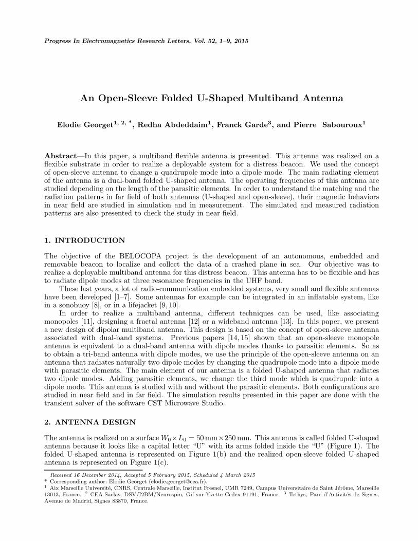
The reflection coefficient S11 of the folded U-shaped antenna was measured in an anechoic chamber onthe frequency band [300–2300] MHz. In Figure 2, the simulated and measured reflection coefficients arerepresented in continuous and discontinuous line respectively. The measured S11 coefficient does notmatch the simulated S11 coefficient perfectly because the sewing of the U-shaped part of the antennacauses some geometric distortions not taken into account in the simulation. Nevertheless, the simulatedand measured results are in agreement, we can note four resonant modes. The first mode is locatedat the frequency f1 = 590 MHz, this frequency is done by length LA = (L1 + d2) = λ1/4, with λi
the wavelength of the ith mode. The second mode is at f2 = 875 MHz corresponding to the lengthLB = L2 − d2 = 1.1(λ2/4). The second mode is better matched in measurement than in simulation.The two other resonance frequencies, f3 = 2.8 × f1 = 1670 MHz and f4 = 2.5 × f2 = 2150 MHz,correspond to the quadrupole modes generated by the length LA and LB respectively. The behavior ofthis antenna can be approximated by the combination of two uncoupled dipoles with lengths LA andLB.
Progress In Electromagnetics Research Letters, Vol. 52, 2015 3
Figure 2. Reflection coefficient |S11| (dB) of thefolded U-shaped in simulation (continuous line)and in measurement (discontinuous line).
Figure 3. Scanned surface in near field of thefolded U-shaped antenna.
3.2. Near Field Results
To understand the behavior of the antenna in far field, the magnetic field is studied. Indeed, the currentdistribution along the radiating elements of the antenna provides a complete description of the radiationpattern. To do this, we developed an experimental setup to measure the magnetic field at a studiedpoint
−−−→H(x) above the antenna since it is directly proportional to the current distribution in the studied
space−−−→J(x′) [18]:
−−−→H(x) =
1μ0
∇×(
μ0
4π
∫ −−−→J(x′)
eik|x−x′|
|x − x′| d3x′)
(1)
μ0 the permeability of free space, k the wavenumber, x the studied point and x′ a point in the studiedspace. For the configuration of our antenna, only Hx and Hz participate to the radiations. The Hx
component has a vertical symmetry, and the Hz component has vertical and horizontal symmetry.Because our antennas are geometrically symmetric on the vertical axis, the Hx component is sufficientto describe the nature of the studied mode. We plot the real part of the field, because it gives informationon the amplitude and phase of Hx. The measurement is realized in an anechoic chamber thanks to a3D axis positioning system. The probe is a magnetic loop with d = 5mm diameter (d < (0.03λi),i = {1, 2, 3}). The probe is positioned 7 mm above the antenna (7mm < 0.04λi). The magnetic field ismeasured on a surface delimited by the red rectangular in Figure 3.
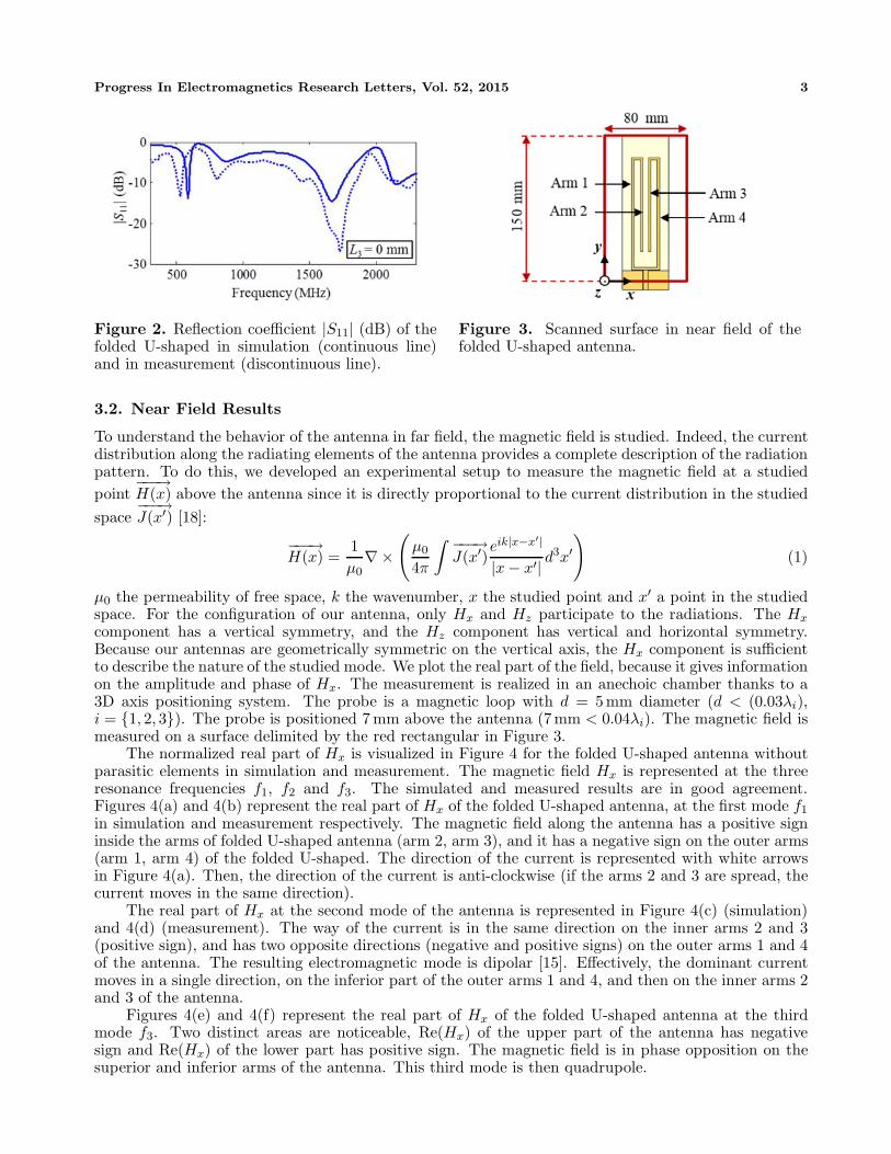
The normalized real part of Hx is visualized in Figure 4 for the folded U-shaped antenna withoutparasitic elements in simulation and measurement. The magnetic field Hx is represented at the threeresonance frequencies f1, f2 and f3. The simulated and measured results are in good agreement.Figures 4(a) and 4(b) represent the real part of Hx of the folded U-shaped antenna, at the first mode f1
in simulation and measurement respectively. The magnetic field along the antenna has a positive signinside the arms of folded U-shaped antenna (arm 2, arm 3), and it has a negative sign on the outer arms(arm 1, arm 4) of the folded U-shaped. The direction of the current is represented with white arrowsin Figure 4(a). Then, the direction of the current is anti-clockwise (if the arms 2 and 3 are spread, thecurrent moves in the same direction).
The real part of Hx at the second mode of the antenna is represented in Figure 4(c) (simulation)and 4(d) (measurement). The way of the current is in the same direction on the inner arms 2 and 3(positive sign), and has two opposite directions (negative and positive signs) on the outer arms 1 and 4of the antenna. The resulting electromagnetic mode is dipolar [15]. Effectively, the dominant currentmoves in a single direction, on the inferior part of the outer arms 1 and 4, and then on the inner arms 2and 3 of the antenna.
Figures 4(e) and 4(f) represent the real part of Hx of the folded U-shaped antenna at the thirdmode f3. Two distinct areas are noticeable, Re(Hx) of the upper part of the antenna has negativesign and Re(Hx) of the lower part has positive sign. The magnetic field is in phase opposition on thesuperior and inferior arms of the antenna. This third mode is then quadrupole.

4 Georget et al.
(a) (b)
(c) (d)
(e) (f)
Figure 4. Normalized Re(Hx) map of the folded U-shaped antenna at f1 in (a) simulation and(b) measurement, at f2 in (c) simulation and (d) measurement, and at f3 in (e) simulation and(f) measurement. The arrows show the direction of the current on the left half of the antenna.
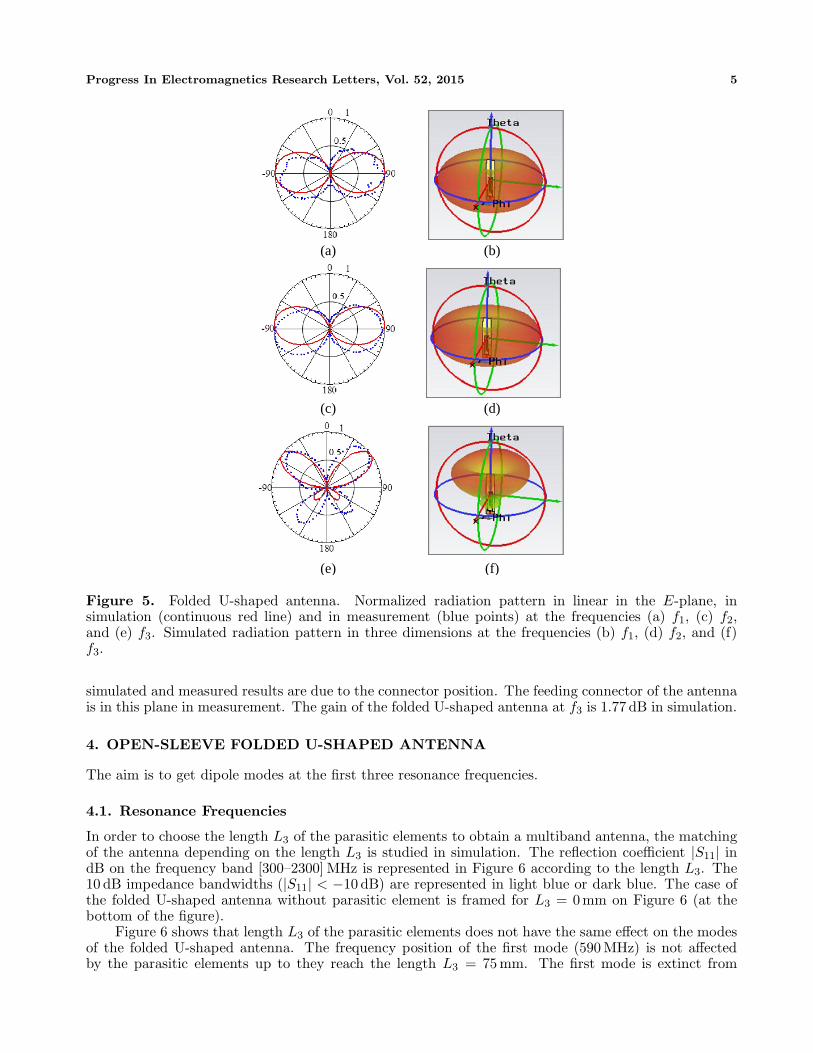
3.3. Far Field Results
The radiation patterns of the folded U-shaped antenna are represented on Figure 5 for the three firstresonance frequencies. The radiations are visualized in three dimensions thanks to the simulationresults. The radiation patterns are measured in the anechoic chamber of Centre Commun de Ressourcesen Microondes (C.C.R.M., Marseille, France). The distance between the antenna under test and thereceiver antenna is 8.40 m [14]. The antenna is positioned vertically at the center of the polar coordinates.The top of the antenna is at θ = 0◦, and the ground plane is at θ = +/ − 180◦.
The differences between simulation and experiment results are due to the geometric differencesbetween the designed and realized antenna. Indeed, the distortions induced with the sewing of the U-shaped part on the flexible substrate are not simulated. For the two first resonance frequencies f1 andf2 (Figures 5(a)–(d)), the radiation patterns are actually dipolar in simulation and measurement. Thegains in simulation are similar for f1 (1.34 dB) and f2 (1.39 dB). At the third resonance frequency f3
(Figures 5(e)–(f)), the radiation patterns in simulation and measurement are quadripolar, as expectedfrom the conclusions in near field. The quadripolar patterns are asymmetric due to the ground plane(smaller lobes in the inferior part). The differences of amplitude of the two inferior lobes between the
Progress In Electromagnetics Research Letters, Vol. 52, 2015 5
(a) (b)
(c) (d)
(e) (f)
Figure 5. Folded U-shaped antenna. Normalized radiation pattern in linear in the E-plane, insimulation (continuous red line) and in measurement (blue points) at the frequencies (a) f1, (c) f2,and (e) f3. Simulated radiation pattern in three dimensions at the frequencies (b) f1, (d) f2, and (f)f3.
simulated and measured results are due to the connector position. The feeding connector of the antennais in this plane in measurement. The gain of the folded U-shaped antenna at f3 is 1.77 dB in simulation.
4. OPEN-SLEEVE FOLDED U-SHAPED ANTENNA
The aim is to get dipole modes at the first three resonance frequencies.
4.1. Resonance Frequencies
In order to choose the length L3 of the parasitic elements to obtain a multiband antenna, the matchingof the antenna depending on the length L3 is studied in simulation. The reflection coefficient |S11| indB on the frequency band [300–2300] MHz is represented in Figure 6 according to the length L3. The10 dB impedance bandwidths (|S11| < −10 dB) are represented in light blue or dark blue. The case ofthe folded U-shaped antenna without parasitic element is framed for L3 = 0mm on Figure 6 (at thebottom of the figure).
Figure 6 shows that length L3 of the parasitic elements does not have the same effect on the modesof the folded U-shaped antenna. The frequency position of the first mode (590 MHz) is not affectedby the parasitic elements up to they reach the length L3 = 75 mm. The first mode is extinct from

6 Georget et al.
Figure 6. Reflection coefficient |S11| (dB) ofthe folded U-shaped antenna on the frequencyband [300–2300] MHz depending on the length ofthe parasitic elements L3.
Figure 7. Reflection coefficient |S11| (dB)of the open-sleeve folded U-shaped antenna insimulation (continuous line) and in measurement(discontinuous line).
this length, this gives the maximum length of the parasitic elements (L3 = 75 mm). The frequencyposition of the second resonance frequency is few affected by the parasitic elements up to they reachL3 = 75 mm. The second mode is also extinct at the length L3 = 75 mm. However, the matching ofthe second mode is better with the parasitic elements. For the third mode, the resonance frequency isvery affected by the length L3. When the parasitic elements are longer, the third mode resonates in alower frequency. From L3 = 40 mm, the resonance frequency of the second and third modes are closeto constitute a wideband mode.
With this configuration, a dual-band antenna is obtained with a narrow band dipole mode and asecond wideband mode, assumed dipole. In order to validate our supposition, the length of the parasiticelements was chosen L3 = 46 mm (framed in the middle on Figure 6). The folded U-shaped antenna withparasitic elements of length L3 = 46 mm is called the open-sleeve folded U-shaped antenna. Figure 7shows the reflection coefficients in simulation and in measurement of this antenna. The first mode insimulation and in measurement is at the frequency f ′
1 = 550 MHz. In simulation, the second modeis a wideband mode as explained previously. In measurement, some differences appear. However, thethird mode is lower in frequency compared to the third mode the folded U-shaped antenna withoutparasitic elements. The second and third mode in measurement are at the frequencies f ′
2 = 850 MHzand f ′
3 = 1010 MHz respectively.
4.2. Near Field Results
Figure 8 shows the normalized real part of Hx of the open-sleeve folded U-shaped antenna with parasiticelements (L3 = 46 mm), in simulation and measurement at the three resonance frequencies f ′
1, f ′2 and
f ′3. The results in simulation and measurement are in good agreement. Figures 8(a) and 8(b) represent
the real part of Hx at the first mode f ′1 of the open-sleeve folded U-shaped antenna.
The magnetic field is in phase opposition on the inner and outer tracks of the antenna, so theparasitic elements do not alter the first dipole mode.
The real part of Hx at the second mode of the open-sleeve antenna is represented in Figure 8(c)in simulation and 8(d) in measurement. The magnetic field has a dipolar behavior on the inner tracks,and a quadripolar behavior on the outer tracks of the folded U-shaped. As for the parasitic elements,they have a dipolar behavior in phase opposition to the inner tracks. This mode at f ′
2 keeps the dipolarbehavior, the adding of the parasitic elements behaves like a matching circuit.
Figures 8(e) and 8(f) represent the real part of Hx of the open-sleeve antenna at the third mode f ′3.
The magnetic field has still a quadripolar behavior on the folded U-shape of the open-sleeve antenna.Along the folded U-shaped, the two parts positive and negative of Re(Hx) on Figure 4(f) have oppositesigns to the two parts of Re(Hx) of the quadrupole mode of the folded U-shaped antenna (Figures 4(e)and 4(f)). This difference is explained by the different position of the third resonance frequency of theantenna with and without the parasitic elements. The parasitic elements have a dipolar behavior, andthe inferior part of the quadrupole mode is bypassed. This mode presents a dipole mode, like the caseof the open-sleeve monopole antenna [15].

Progress In Electromagnetics Research Letters, Vol. 52, 2015 7
(a) (b)
(c) (d)
(e) (f)
Figure 8. Normalized Re(Hx) map of the open-sleeve folded U-shaped antenna (L3 = 46 mm) at f ′1
in (a) simulation and (b) measurement, at f ′2 in (c) simulation and (d) measurement, and at f ′
3 in(e) simulation and (f) measurement. The arrows show the direction of the current on the left half ofthe antenna.
4.3. Far Field Results
When the parasitic elements are added to the folded U-shaped antenna, the three radiation patternson Figure 9 are obtained. In the same way as the radiation patterns of the folded U-shaped antenna(Figure 5), some differences between simulation and measurement result are due to the difficulty tosimulate the realized antenna with the ripples of the sewing. The radiation patterns at the three firstresonance frequencies are dipolar in simulation and in measurement.
In simulation, the gains of the open-sleeve folded U-shaped antenna are 1.35 dB at the first resonancefrequency f ′
1, 1.42 dB at the second resonance frequency f ′2 and 1.47 dB at the third resonance frequency
f ′3.
The quadrupole mode of the folded U-shaped antenna has been changed into a dipole mode addingparasitic elements that resonate at the third mode.

8 Georget et al.
(a) (b)
(c) (d)
(e) (f)
Figure 9. Open-sleeve folded U-shaped antenna (L3 = 46 mm). Normalized radiation pattern in linear,in the E-plane in simulation (continuous red line) and in measurement (blue points) at the frequencies(a) f ′
1, (c) f ′2, and (e) f ′
3. Simulated radiation pattern in three dimensions at the frequencies (b) f ′1, (d)
f ′2, and (f) f ′
3.
5. CONCLUSION
With the study of this folded U-shaped antenna, we are able to realize a multiband antenna thanks tothe adding of the parasitic elements. Two modes of this antenna can be tuned modifying the dimensionsof the folded U-shaped antenna whereas the third mode is generated through the parasitic elements.The advantage of this antenna is the matching in term of resonance frequency for the third mode.Indeed, we can obtain a tri-band antenna or a dual-band wideband antenna depending on the parasiticelements length.
The aim of this work is to realize an ejected maritime beacon during an aircraft crash in the sea(BELOCOPA project). Initially, the antenna was studied in free space.
ACKNOWLEDGMENT
This work was supported by the French Fonds Unique Interministeriel, with the support of the ProvenceAlpes Cote d’Azur Region and Bpifrance in the context of the BELOCOPA project. Redha Abdeddaimis thankful for a PEPS CNRS funding through project CLOAK EXTERNE.

Progress In Electromagnetics Research Letters, Vol. 52, 2015 9
REFERENCES
1. De Cos, M. E. and F. Las-Heras, “Polypropylene-based dual-band CPW-fed monopole antenna,”IEEE Antennas Propag. Mag., Vol. 55, No. 3, 264–273, Jun. 2013.
2. Paul, D. L., L. Zhang, and L. Zheng, “Flexible dual-band LCP antenna for RFID applications,”Proc. IEEE EMTS, 973–976, Hiroshima, Japan, May 2013.
3. Salam, A., A. Khan, and M. S. Hussain, “Dual band microstrip antenna for wearable applications,”Microw. Opt. Technol. Lett., Vol. 56, No. 4, 916–918, Apr. 2014.
4. Wang, Z., L. Z. Lee, D. Psychoudakis, and J. Volakis, “Embroidered multiband body-worn antennafor GSM/PCS/WLAN communications,” IEEE Trans. Antennas Propag., Vol. 62, No. 6, 3321–3329, Jun. 2014.
5. Khaleel, H. R., H. M. Al-Rizzo, and D. G. Rucker, “Compact polyimide-based antennas for flexibledisplays,” IEEE Journal of Display Technology, Vol. 8, No. 2, 91–97, Feb. 2012.
6. Abbosh, A. I., R. F. Babiceanu, H. Al-Rizzo, S. Abushamleh, and H. R. Khaleel, “Flexible Yagi-Uda antenna for wearable electronic devices,” APSURSI IEEE, 1200–1201, Orlando, FL, USA,Jul. 2013.
7. Raad, H. R., A. I. Abbosh, H. M. Al-Rizzo, and D. G. Rucker, “Flexible and compact AMC basedantenna for telemedicine applications,” IEEE Trans. Antennas Propag., Vol. 61, No. 2, 524–531,Feb. 2013.
8. Min, K.-S., Y.-H. Park, and K.-W. Im, “Design for sonobuoy transmitting antenna for anti-submarine warfare,” Proc. IEEE Antennas Propag. Int. Symp., 1201–1204, Sendai, Japan,Aug. 2004.
9. Serra, A. A., P. Nepa, and G. Manara, “A wearable two-antenna system on a life jacket forCospas-Sarsat personal locator beacons,” IEEE Trans. Antennas Propag., Vol. 60, No. 2, 1035–1042, Feb. 2012.
10. Lilja, J., et al., “Body-worn antennas making a splash: Lifejacket-integrated antennas for globalsearch and rescue satellite system,” IEEE Antennas Propag. Mag., Vol. 55, No. 2, 324–341,Apr. 2013.
11. Chu, Q.-X. and L.-H. Ye, “Design of compact dual-wideband antenna with assembled monopoles,”IEEE Trans. Antennas Propag., Vol. 58, No. 12, 4063–4066, Dec. 2010.
12. Li, D. and J. Mao, “Sierpinskized Koch-like sided multifractal dipole antenna,” Progress InElectromagnetics Research, Vol. 130, 207–224, 2012.
13. Durgun, A. C., C. A. Balanis, C. R. Birtcher, and D. R. Allee, “Design, simulation, fabricationand testing of flexible bow-tie antennas,” Proc. IEEE Radio and Wireless Symp., 50–53, Phoenix,AZ, USA, Jan. 2011.
14. Georget, E., R. Abdeddaim, and P. Sabouroux, “Analytical, simulation and measurement studiesof a dual-band open-sleeve curved meander line antenna on a flexible substrate,” Progress InElectromagnetics Research, Vol. 145, 49–57, 2014.
15. Georget, E., R. Abdeddaim, and P. Sabouroux, “AMTA corner: A new method to design a multi-band flexible textile antenna,” IEEE Antennas Propag. Mag., Vol. 56, No. 3, 240–248, Jun. 2014.
16. Nicolson, M. and G. F. Ross, “Measurement of the intrinsic properties of materials by time-domaintechniques,” IEEE Trans. Intrum. Meas., Vol. 19, No. 4, 377–382, Nov. 1970.
17. Georget, E., R. Abdeddaim, and P. Sabouroux, “A quasi-universal method to measure theelectromagnetic characteristics of usual materials in the microwave range,” Comptes Rendus —Physique, Vol. 15, No. 5, 448–457, May 2014.
18. Jackson, J. D., “Radiating systems, multipole fields and radiation,” Classical Electrodynamics, 3rdedition, 407–455, Wiley, New York, 1962.


![Multiband Transceivers - [Chapter 1]](https://img.pdfslide.net/doc/110x75/55cf041ebb61ebb0078b482c/multiband-transceivers-chapter-1.jpg)

