Embed Size (px)
Citation preview

Aperture
• An opening in the barrier layer of the screen through
which the material to be applied can pass

Screen Printing
• Screens consist of a mesh that is impregnated with an emulsion
• Mesh number: holes per square inch
• Apertures are formed by the exclusion of emulsion fromselected areas
• Lithographic techniques
• Wire diameter and mesh number determine paste type to beused
• Approximately 50% open area in aperture
Screen Printing
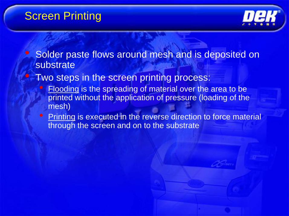
• Solder paste flows around mesh and is deposited on substrate
• Two steps in the screen printing process:• Flooding is the spreading of material over the area to be
printed without the application of pressure (loading of the mesh)
• Printing is executed in the reverse direction to force material through the screen and on to the substrate

‘Flood’
Basic Screen Process

‘Print’
Basic Screen Process

Screen Printing
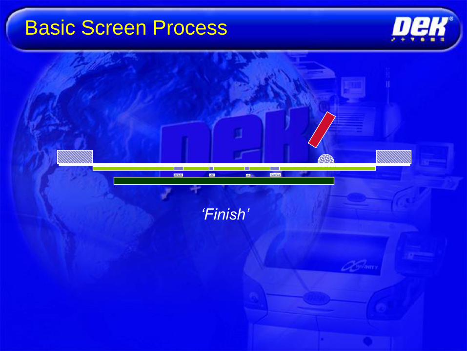
‘Finish’
Basic Screen Process

15mm Dia.
Paste
Zero ‘Print Gap’
Basic Stencil Process

Paste
Rolling
Controlled ‘Print Speed’
Even ‘Squeegee Pressure’
Basic Stencil Process

Board is lowered under controlled
‘Separation Speed’
Basic Stencil Process

Stencil Printing
• Four phases of stencil printing
• On-contact method shown

Stencil Printing
• Stencils consist of a metal foil through
which holes are opened to allow the
passage of material
• Apertures are formed by the machining of
the foil
• Stainless steel, molybdenum, brass, nickel
• 100% open area in aperture

Stencils vs. Screens

Capable of smaller than stencil
size deposits

The Perfect Print
• Clean edges
• Flat on top
• Height = Stencil Thickness
• Good Alignment
• No Flux Bleed ...

• Clean edges
• Flat on top
• Height = Stencil
thickness
• Good alignment
• No flux bleed
PERFECT PRINT


Issue 2 - 06 November 2001
INITIALISATION
SET-UP
MAINTENANCE
PASTE CARTRIDGE LOW
PAPER EMPTY
SOLVENT EMPTY
OPERATIONAL
WAITING IN READY STATE
SYSTEM POWER OFF
HALTED BY ERROR
BEACON INDICATIONS


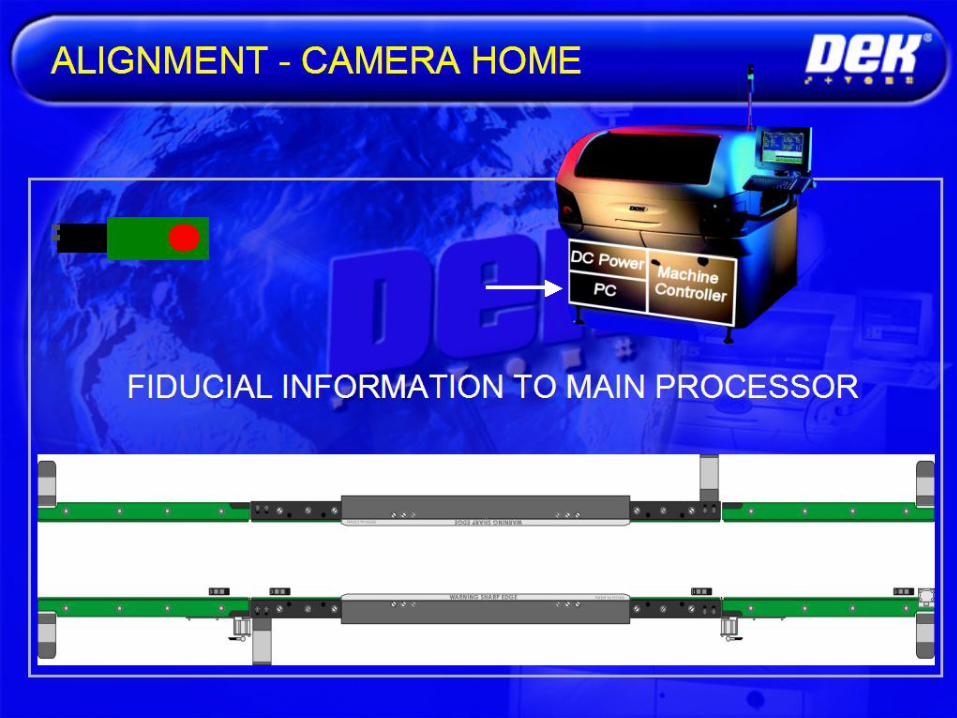

Note: Some machines fix stencil, move board instead.
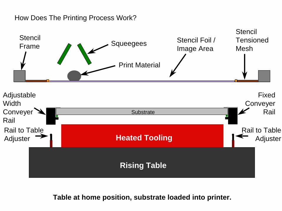
Table at home position, substrate loaded into printer.
Company Confidential
Stencil Foil /
Image Area
Substrate
Squeegees
Print Material
Stencil
Tensioned
Mesh
Stencil
Frame
Adjustable
Width
Conveyer
Rail
Fixed
Conveyer
Rail
Rising Table
Heated ToolingRail to Table
Adjuster
Rail to Table
Adjuster
Table at home position, substrate loaded into printer.
Company Confidential
Stencil Foil /
Image Area
Substrate
Squeegees
Print Material
Stencil
Tensioned
Mesh
Stencil
Frame
Adjustable
Width
Conveyer
Rail
Fixed
Conveyer
Rail
Rising Table
Heated ToolingRail to Table
Adjuster
Rail to Table
Adjuster
How Does The Printing Process Work?

Table raised to vision height, establishing tooling contact with substrate.
Company Confidential
Camera
Substrate
Rising Table
Heated Tooling
Table raised to vision height, establishing tooling contact with substrate.
Company Confidential
Camera
Substrate
Rising Table
Heated Tooling
How Does The Printing Process Work?

After fiducial capture and stencil position is adjusted to achieve correct
alignment, table raises substrate to print height.
Company Confidential
Substrate
Rising Table
Heated Tooling
After fiducial capture and stencil position is adjusted to achieve correct
alignment, table raises substrate to print height.
Company Confidential
Substrate
Rising Table
Heated Tooling
How Does The Printing Process Work?

Squeegee contacts print material, downward pressure applied.
Company Confidential
Substrate
Rising Table
Heated Tooling
Squeegee contacts print material, downward pressure applied.
Company Confidential
Substrate
Rising Table
Heated Tooling
How Does The Printing Process Work?

Squeegee pushes print material along stencil.
Company Confidential
Substrate
Rising Table
Heated Tooling
Squeegee pushes print material along stencil.
Company Confidential
Substrate
Rising Table
Heated Tooling
How Does The Printing Process Work?

Squeegee reaches end of stroke (print limit).
Company Confidential
Substrate
Rising Table
Heated Tooling
Squeegee reaches end of stroke (print limit).
Company Confidential
Substrate
Rising Table
Heated Tooling
How Does The Printing Process Work?

Table lowered, initiating substrate separation from stencil.
Company Confidential
Substrate
Rising Table
Heated Tooling
Table lowered, initiating substrate separation from stencil.
Company Confidential
Substrate
Rising Table
Heated Tooling
How Does The Printing Process Work?

Table moves to home position and substrate is transported out of printer.
Company Confidential
Substrate
Rising Table
Heated Tooling
Table moves to home position and substrate is transported out of printer.
Company Confidential
Substrate
Rising Table
Heated Tooling
How Does The Printing Process Work?

What is Solder Paste ?
Alloy (solder powder)
Flux
Gelling Agents
100% 100%
~50%
Solder
by
volume
~90%
Solder
by
Weight
~50%
~10%

What does the Flux do ??
Flux ensures successful solder joint is formed between
component and pad
Suspends the powder
Provides correct rheology and tackiness
Cleans surface
Removes oxide from solder powder
Protects surface
Leaves safe residues...

What are gelling agents ??
• Makes the flux shear thinning, pseudoplastic (time independent) or thixotropic (time dependent)
Paste viscosity moves up and down this plot
depending on where it is in the print process.newtonic
Shear rate (s-1)
Viscosity

Temperature v. viscosity
The temperature - viscosity relationship for a typical no clean paste
100
110
120
130
140
150
15 20 25 30 35
Temperature (deg c)
Vis
co
sit
y (
Pa.s
)

Printing Rheology
• Ideal paste ispseudoplastic; most pastesare thixotropic to somedegree
• Viscosity will changethroughout the printingprocess• Allows for deposition and
retention of material

Printability
• Accuracy and repeatability of paste deposits
• Acceptance criteria include
• Deposited paste weight from print to print should not exceed
10%
• Deposit height should have a tolerance of 1 mil from deposit
to deposit within a print
• Uniform coverage without tailing or separation

Working Life
• Time between jar opening and shift of the
rheological properties of the material
outside the process window
• Working life can be checked by examining
print quality and checking tackiness
• Won‟t hold components in place prior to reflow

Slump Testing
• Standards for slump testing
• Print paste on test board of various pitch land
patterns
• Failure if deposits bridge after printing
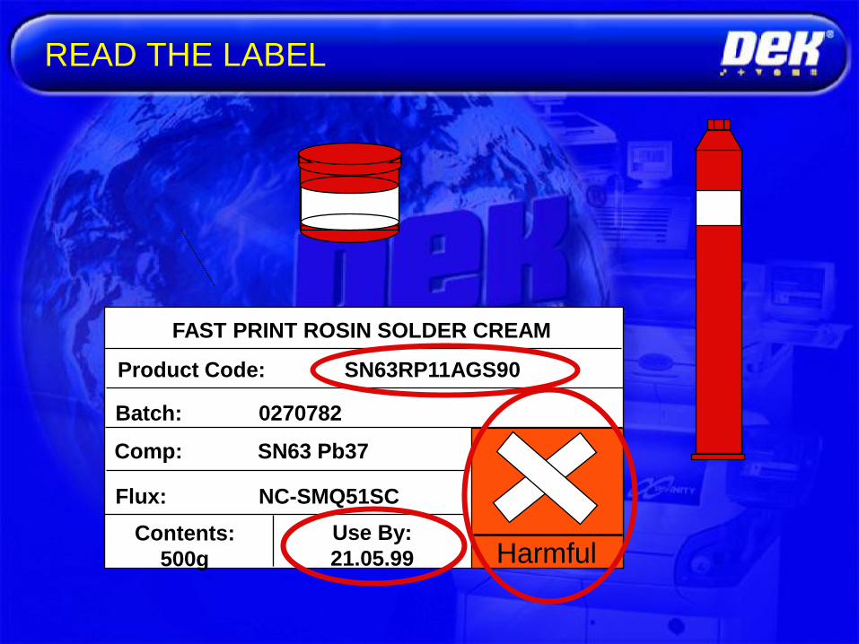
READ THE LABEL
Harmful
Product Code: SN63RP11AGS90
FAST PRINT ROSIN SOLDER CREAM
Comp: SN63 Pb37
Flux: NC-SMQ51SC
Batch: 0270782
Contents:
500g
Use By:
21.05.99

Solder Paste - Read the Label!
Product Code: SN63 RP11 AGS 90
FAST PRINT ROSIN SOLDER CREAM
Alloy Type
63 % Tin / 37% Lead
(or 35% lead / 2% Silver)
Flux Medium Type
„Rosin Product‟
Particle Size
Type 3 (45 - 20 um)
Metal Content
90% (by weight)

Solder Powder
Type 2 Powder Type 3 Powder
Consistent alloy, particle size and particle shape.
Oxide free
53 - 38 um 45 - 20 um
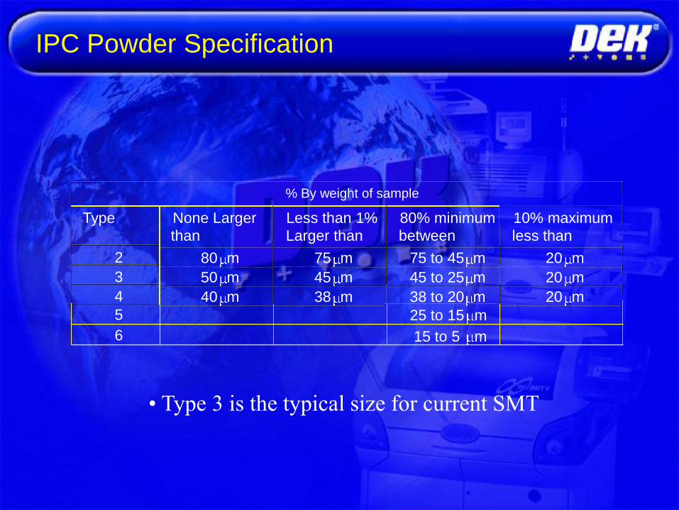
IPC Powder Specification
• Type 3 is the typical size for current SMT
% By weight of sample
Type None Larger
than
Less than 1%
Larger than
80% minimum
between
10% maximum
less than
2 80 m 75 m 75 to 45 m 20 m
3 50 m 45 m 45 to 25 m 20 m
4 40 m 38 m 38 to 20 m 20 m
5
6
25 to 15 m
15 to 5 m
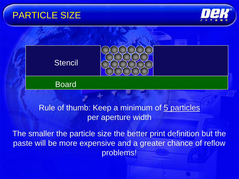
The smaller the particle size the better print definition but the
paste will be more expensive and a greater chance of reflow
problems!
Rule of thumb: Keep a minimum of 5 particles
per aperture width
Stencil
Board
PARTICLE SIZE

Good Working Practices
• Stir Paste Gently Before Use
• Regulate Paste Diameter at 15mm
• Perform Small Top-Ups Regularly
• Regulate Temperature and Humidity
• Do Not Leave Paste drying on Stencil ...

PASTE STORAGE

PASTE STORAGE
• First In First Out (FIFO)
Clearly label date in and date out
• Rotate jars and tubes regularly
• Store tubes upright
• Correct temperature

Maybe,
Temporary &
Overnight
Definitely for
3 - 6 months Never!
PASTE STORAGE

Considerations:
• Do you use squeegee paste deflectors to reduce
solder paste trails?
• Do you put solder paste trails back into working
paste?
• What do you do with the paste over a lunch break?
• How long will your solder paste remain workable?
• When to dispose of your paste?
• Do you have ProFlow?
REUSE AND DISPOSAL PROCEDURE

Considerations:
• Storage procedure
• Stock levels
• Availability
• FIFO
• Expiry date
• Stabilise temperature before use
PASTE STORAGE

USING THE PASTE
Cold
Storage
„Working Pot‟
Printer
Fresh Paste
Place in machine
After 8 Hours
End of Run / Extended Downtime
End of Day
Harmful
Disposal
Return only if paste quality
is good and it makes
economic sense
„Temporary Pot‟

• Good stencil
• Excellent results
• Few failures
• Predictable yields
GOOD/BAD STENCIL
• Poor stencil
• Lots of stencil wiping/cleaning
• Lots of bridging and open circuits

Remember, stencils are fragile......
• Store and handle with care
• Adequate storage
• Keep stencils clean
• Inspect for damage and stretch
• Repair fiducials when damaged
• Product coded to reduce mistakes
STENCIL MAINTENANCE

Manual:
• Use a lint free cloth
• Solvent soaked cloth in each hand, clean both
sides simultaneously
Dedicated Screen cleaner:
• Recommended
STENCIL CLEANING
Underscreen cleaner set-up (later)

• Better to have excellent low-tech stencil than
poor high-tech stencil.
• Correct stencil dimensions are vital in order
to achieve good prints.
• A great machine can do little to correct a
fundamentally flawed stencil.
• Ensure stencil is thoroughly clean
• Correct stowage
• Repair fiducials
BEST WORKING PRACTICES

Chemical Etching
• Image patterned on both sides simultaneously
• Parallel fabrication of
apertures
• Hourglass profile (~ ½ mil)
• Difficult to release solder
paste from apertures
• Paste deposit „hangs‟ on
girdle and does not
release well

Chemical Etching
• Over- and under-etching
• Etch is both vertical and horizontal
• Must allow for growth in both dimensions

Laser Cutting
• Fabrication by cutting holes in foil with
high-power laser
• Gerber data used to drive cutting tools
• Serial process- more expensive than etching
• Aperture size minimum 2 mil
• Tolerance .2-.3 mil

Laser Cutting
• Buildup of debris on surface
• Rough side walls
• Electropolishing used to polish side walls
• Selective chemical etch
• Don‟t want too smooth a stencil top

Laser cutting
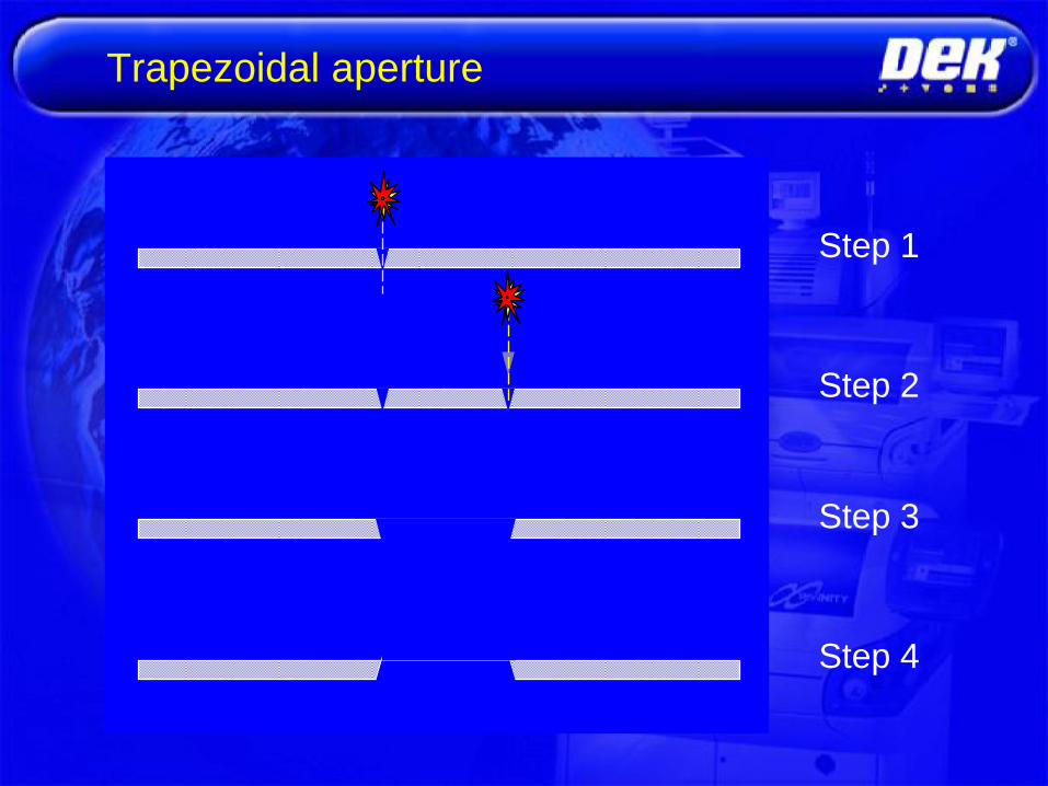
Trapezoidal aperture
Step 3
Step 1
Step 2
Step 4
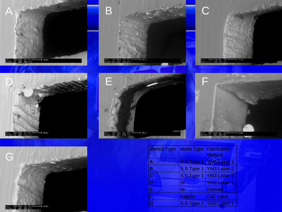
YAG Laser 1S.S Type 2G
Co2 LaserKaptonF
FormedNiE
YAG Laser 1NiD
YAG Laser 3S.S Type 1C
YAG Laser 2S.S Type 1B
YAG Laser 1S.S Type 1A
Fabrication
Method
Metal TypeStencil Type
YAG Laser 1S.S Type 2G
Co2 LaserKaptonF
FormedNiE
YAG Laser 1NiD
YAG Laser 3S.S Type 1C
YAG Laser 2S.S Type 1B
YAG Laser 1S.S Type 1A
Fabrication
Method
Metal TypeStencil Type
A B C
D E F
G

Electroforming
• Image built up to desired thickness in plating bath• Nickel built up around apertures created by pattern
• Very tight and smooth aperture tolerances• Aspect ratio 1.1-1.2 (width:thickness)
• 1-12 mil thickness
• May be too smooth in
some cases

Nickel/Brass
• Electroless nickel plated as the wear layer
over etched brass
• Easier fabrication with brass foil
• Lower surface tension with paste for longer
equipment life
• Tolerances comparable with etched
stencils

Stencil Selection
ChemicalEtching
LaserCut
Electro-formed
Hybrid
Cost Cost effective Cost effective Expensive Less Expensive
Accuracy OK Very Very Mixed
Min. Aperturesize
0.2mm(0.4mmPitch)
No Limit! No Limit! No Limit!
Aperture Shape
Material Stainless SteelBrass
Stainless Steel Nickel Alloy Stainless SteelBrass
?
Fiducials Good Good Weak Good

Aspect Ratio
• Ratio between aperture width and stencil thicknessshould not be smaller than 1.5 for good transfer
• Smaller aspect ratios will result in pad clogging
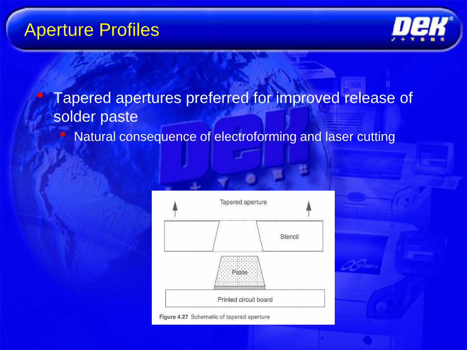
Aperture Profiles
• Tapered apertures preferred for improved release of
solder paste
• Natural consequence of electroforming and laser cutting

Tapered Apertures
• Higher smearing from wider bottom overwhelmed by
consistency from better release
• As pitch decreases, smearing becomes more of an issue
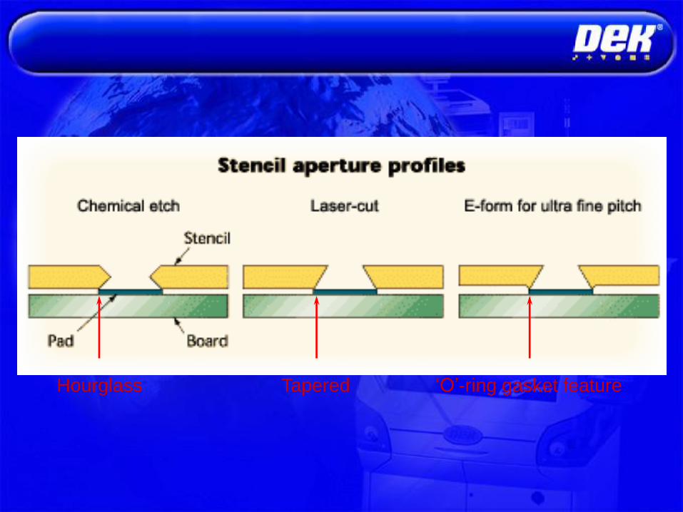
„O‟-ring gasket featureTaperedHourglass

Stencil Contrast

Fine-Pitch Considerations
• Micromodification is the reduction inaperture size to minimize bridging atfine pitch
• „Zipper‟ patterns also increase thepitch between neighboring deposits
• Poor registration or an excess ofsolder outside the lands can lead tothe formation of solder balls (andshorts)

Step-Down Stencils
• Areas of differing thickness used in same stencil to
deliver different paste quantities
• Thin area for fine-pitch devices
• Thick area for coarser pitch components

Stencil Design
Pitch
Length
Width
Design Stencil
Apertures to
allow a clearance
of at least 50 µm
between
Paste and edge
of Pad
Paste
Pad


Paste Transfer Efficiency Trend
Recommended Area Ratio > 0.66

Stencil Design
Release Equation 1
Release Equation 2
W
T
Paste Release Equation
W
Avg.Particle size
> 0.66
>1.5
> 5
W
T
L
L*W
2*(L+W)*T

IPC 7525 – Stencil Design Standard

Stencil thickness determined by finest pitch device.
Aperture opening usually slightly smaller than circuit
board pad.
If area ratio is violated, then aperture to be oversized.
Try to avoid making apertures 1:1 with pad.
Finest spacing between apertures should be more
than the thickness.
Laser cut stencils are most popular for SMT,
electropolishing is common surface treatment.
Fine pitch, small feature, or high aperture count
applications justify Electroforming.
Stencil Design Guidelines
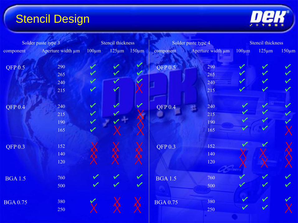
Stencil Design
150µm
Solder paste type 3 Stencil thickness
component Aperture width µm 100µm 125µm
290
265
240
QFP 0.5
215
240
215
190
QFP 0.4
165
152
140
QFP 0.3
120
760BGA 1.5
500
380BGA 0.75
250
Solder paste type 4 Stencil thickness
component Aperture width µm 100µm 125µm 150µm
290
265
240
QFP 0.5
215
240
215
190
QFP 0.4
165
152
140
QFP 0.3
120
760BGA 1.5
500
380BGA 0.75
250

Stencil - Board alignment
• Cause:
• Poor Artwork
• Poor Quality Stencil Manufacture
• Poor board manufacturing
• Board Stretch
• Poor Fiducial Alignment
• Machine not calibrated
• Solution:
• Print Offsets
• Buy New Stencil
• Improve Fiducial Score
• Buy better boards
• Calibrate machine

Printability
• Accuracy and repeatability of paste deposits
• Acceptance criteria include
• Deposited paste weight from print to print should not exceed
10%
• Deposit height should have a tolerance of 1 mil from deposit
to deposit within a print
• Uniform coverage without tailing or separation

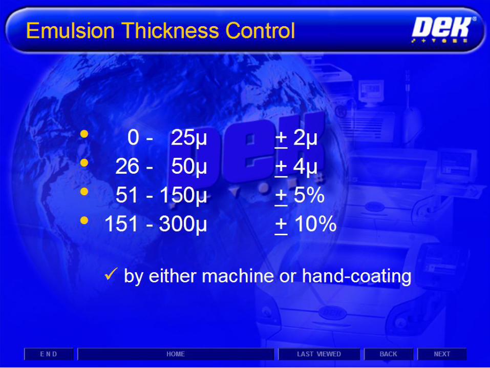
Paste Thickness
• Determines solder volume in joints
• Too thick will bridge
• Too thin will cause insufficients
• Governed by
• Mask thickness (or mesh number and emulsion
thickness for screens)
• Snap-off height
• Overall amount of solder also affected by metal
loading of paste

See anything wrong with these stencil designs?
Deposits are small, but
design is good as long
as there‟s enough alloy
for joint & repeatability.
TE is good, but
bridging will result.
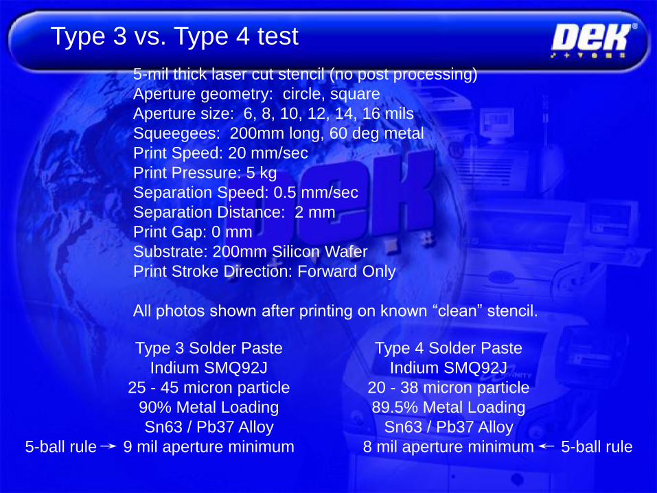
5-mil thick laser cut stencil (no post processing)
Aperture geometry: circle, square
Aperture size: 6, 8, 10, 12, 14, 16 mils
Squeegees: 200mm long, 60 deg metal
Print Speed: 20 mm/sec
Print Pressure: 5 kg
Separation Speed: 0.5 mm/sec
Separation Distance: 2 mm
Print Gap: 0 mm
Substrate: 200mm Silicon Wafer
Print Stroke Direction: Forward Only
All photos shown after printing on known “clean” stencil.
Type 3 Solder Paste
Indium SMQ92J
25 - 45 micron particle
90% Metal Loading
Sn63 / Pb37 Alloy
9 mil aperture minimum
Type 4 Solder Paste
Indium SMQ92J
20 - 38 micron particle
89.5% Metal Loading
Sn63 / Pb37 Alloy
8 mil aperture minimum
Type 3 vs. Type 4 test
5-ball rule 5-ball rule

6-mil Circular Aperture 6-mil Square ApertureT
ype 3
Type 4
Stencil Thickness = 5 mils

8-mil Circular Aperture 8-mil Square ApertureT
ype 3
Type 4
Stencil Thickness = 5 mils
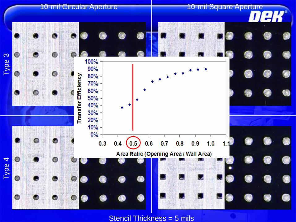
10-mil Circular Aperture 10-mil Square ApertureT
ype 3
Type 4
Stencil Thickness = 5 mils

12-mil Circular Aperture 12-mil Square ApertureT
ype 3
Type 4
Stencil Thickness = 5 mils

14-mil Circular Aperture 14-mil Square ApertureT
ype 3
Type 4
Stencil Thickness = 5 mils


Mesh density specification dictates opening and wire diameter
Mesh thickness determined by wire diameter and weave


Mesh Density = wire count / unit area


Best Result


Mesh Screen Printing Applications
Lower viscosity, smaller particle size materials used
Flux
Adhesive
Underfill
Die Attach
Ink
Frit
Thin uniform coatings
Fine detail lines / high resolution lines & fine features
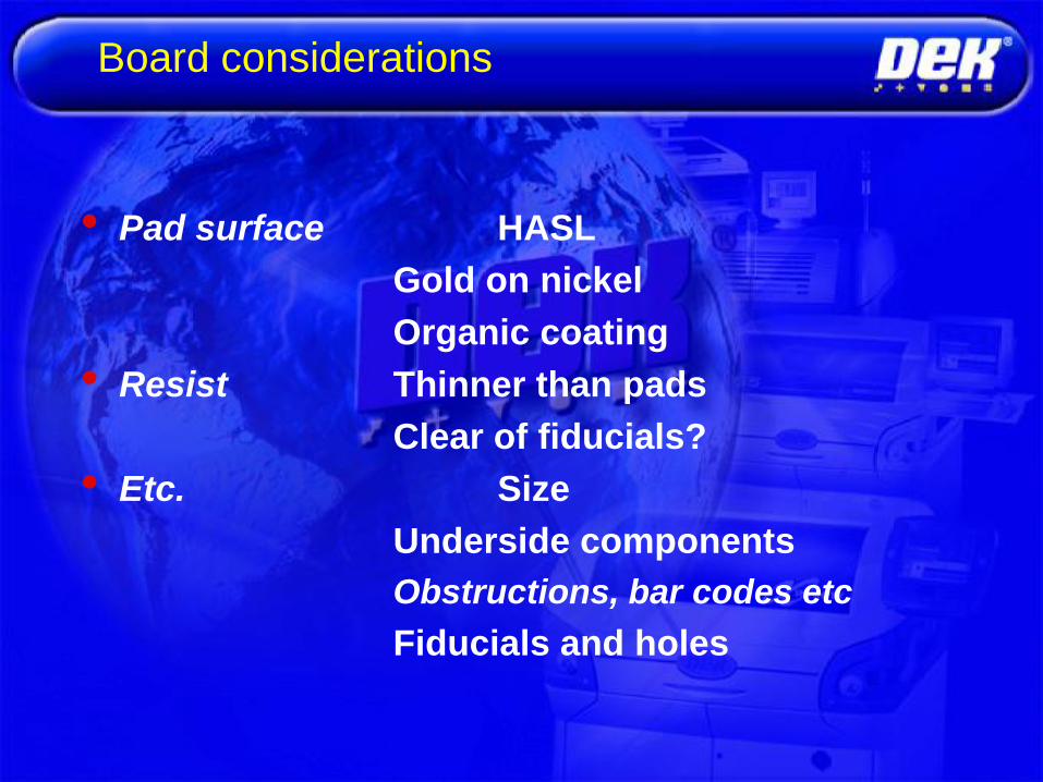
Board considerations
• Pad surface HASL
Gold on nickel
Organic coating
• Resist Thinner than pads
Clear of fiducials?
• Etc. Size
Underside components
Obstructions, bar codes etc
Fiducials and holes

• Fibres
• these can block stencil apertures
• Old Solder
• this can cause solder balls
• Fingerprints
• these can corrode pads, tracks etc
handle board by edges, wear gloves
• Use CM20...
Ensure that production boards are free of ...
Board Issues

• Uneven Pad surface can cause
loss of gasket seal resulting in
bridging etc.
• If the resist is higher that the pad
the gasket seal will be lost
resulting in bridging etc. ...
The board design can impinge on the effectiveness and quality
of the print process. Here are some things to look out for ....
Pad with uneven
surface coating
Pad
Resist
Board Issues

• Underside components can restrict
the use of tooling pins - use tooling
plate or FPA
• Large underside components may
impede board transport - increase
under clearance ...
The board design can impinge on the effectiveness and quality
of the print process. Here are some things to look out for ....
Board Issues

• Via holes can cause problems
with vacuum tooling
• Labels, bar code stickers etc.
increase board thickness leading
to tooling, print and pressure
problems ...
The board design can impinge on the effectiveness and quality
of the print process. Here are some things to look out for ....
Tested ok
Board Issues

• Boards with tapered or
chamfered edges are difficult to
clamp and may be liable to
movement during print leading to
random offsets ...
Rail
Board Issues

• Uneven pad surface
• Solder resist too high
• Underside components restricts tooling
• Via holes with vacuum tooling
QUALITY ISSUES

• Warping and stretch
• Chamfered edges
• Fiducial quality
• Colour changes, surface finish
• Barcode labels
QUALITY ISSUES
||||| || |||| ||| ||||||| ||||||||| |||| |||||
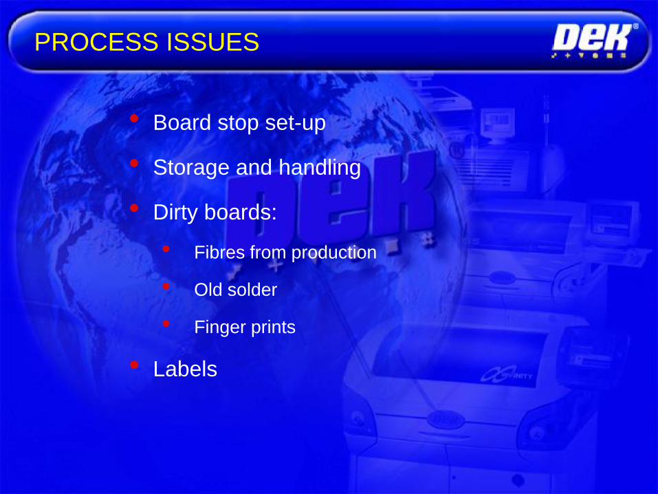
• Board stop set-up
• Storage and handling
• Dirty boards:
• Fibres from production
• Old solder
• Finger prints
• Labels
PROCESS ISSUES
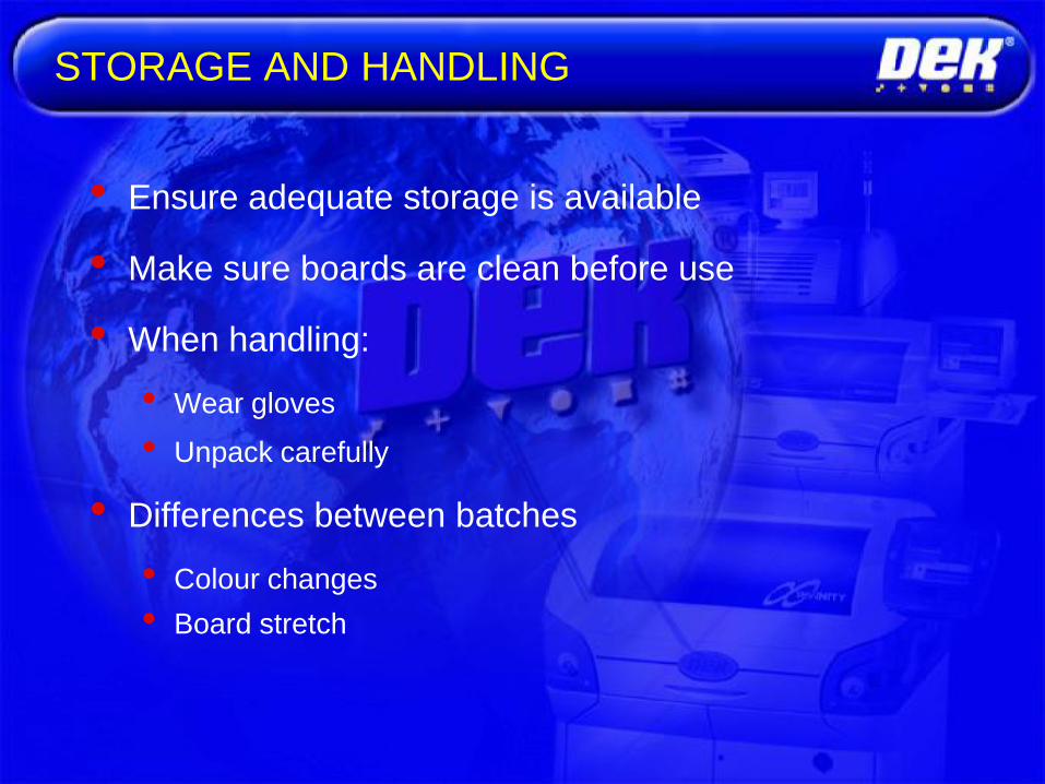
• Ensure adequate storage is available
• Make sure boards are clean before use
• When handling:
• Wear gloves
• Unpack carefully
• Differences between batches
• Colour changes
• Board stretch
STORAGE AND HANDLING

• Handle boards with care and always wear gloves
• Check batches carefully for:
• discolouration, warpage, fiducial quality, thickness of resist,
circuit legends, barcode labels, general board quality
• Ensure board cleanliness
• If boards are washed:
• identify them for inspection before reuse
BEST WORKING PRACTICES

Pitch
Length
Width
A good
design
Paste
Pad
ALIGNMENT

Possible causes:
• Poor quality stencil manufacture
• Poor board manufacturing
• Board stretch or warping
• Poor fiducial alignment
• Machine not calibrated
• Escalate if found
STENCIL - BOARD ALIGNMENT

STENCIL - BOARD ALIGNMENT
Possible solution:
• Improve fiducial score
• Print offsets
• Incorrect batch of boards
• Incorrect position of tooling

Squeegee Materials
• Hardness of material will affect transfer quality• Material will „scoop‟ out
of apertures
• Harder squeegees for
finer pitch printing
• Steel• Thin blade to conform to surface
• Contact angle varied to change applied force
• Will also cause stencil wear

Polyurethane squeegees
• Minimal friction with surface
• Geometry varied to optimize wiping
• Diamond for bi-directional, rectangular for
unidirectional
• Hardness affects scooping of deposits

Pressure
• The greater the angle, the greater the net force on
the squeegee
• Opposing force from fluid is minimized

Squeegee Pressure
• Low pressure can
• Cause skips and ragged edges on deposits
• High pressure can
• Smear deposits
• Damage fine webs or soft squeegees
• Scoop out deposits

Squeegee Effects
• Wear will affect print quality
• Edges that are not straight and sharp will result
in reduced print pressure

Transfer / Driving forces
are influenced by:-
•Squeegee angle
•Print speed
•Paste rheology
•Paste roll volume Driving force
Transfer force
Squeegee Principles
Reaction forceSqueegee force

Squeegee Principles
Paste
rollingStreamlines
Shear rate changes with
position of paste in roll
Lower shear rates
Higher shear rates

Effect of Excess Pressure
Print Direction
Aperture
Scooped
Pads
Board
stencil
„Scooping‟

Angle º
45º 60º
•Intrusive reflow
•High speed printing
•Printing thick stencils
•Printing Glue
•Printing mesh screens
•Standard SMT Printing
Increased
Force
Reduce
Force

Choose the closest length to the board size
Board
Squeegees
Paste
Dry Paste
Gap
LENGTH

• If your specified squeegee is too large………
Use stencil support blocks
LENGTH
Stencil Support Blocks

Note: an average squeegee may travel 5-6 miles in its
lifetime! ……….And that's across a rough surface and under
pressure!
Angle changes
EFFECT OF WEAR
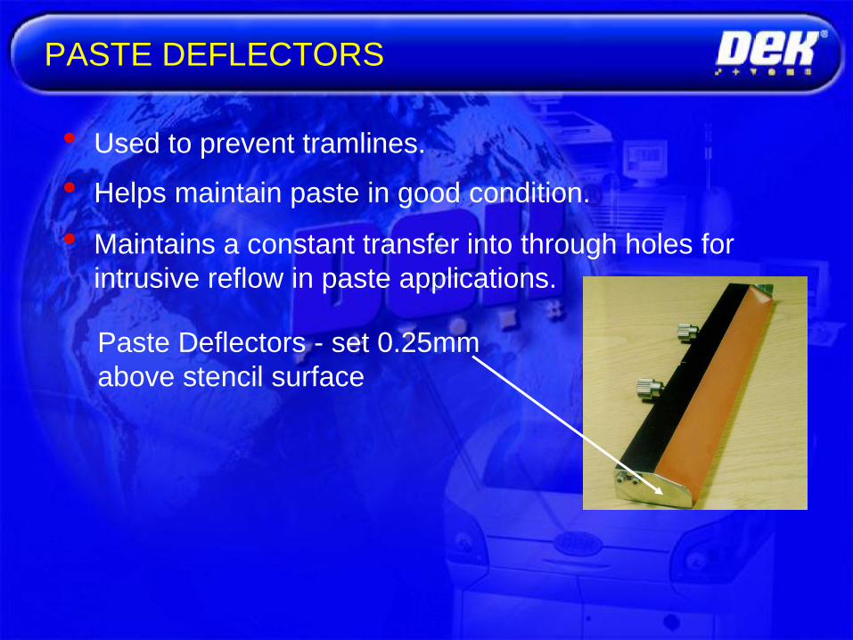
• Used to prevent tramlines.
• Helps maintain paste in good condition.
• Maintains a constant transfer into through holes for
intrusive reflow in paste applications.
Paste Deflectors - set 0.25mm
above stencil surface
PASTE DEFLECTORS

• Polyurethane blades come in trailing edge
and diamond edge profiles.
• Pink (90 - 97 shore) Only for totally flat boards
• Fawn (85 -90 shore)
• Brown (80 - 85 shore)
• Blue (75 -80 shore) Excellent good coarse pitch,
• Robust, boards but must be straight
• Green polyurethane (70 - 75 shore)
• Only for screen printing
• Metal
• Excellent coarse and fine pitch
MATERIAL SELECTION

Polyurethane
Shore 65-85 (Dek Green)
Too Flexible for stencil printing, used only in mesh applications
Shore 95 (Dek Red)
Will need replacing or regrinding after 25000 prints.
Essential to control squeegee pressure to reduce scooping.
Causes little damage.
Commonly used in SMT.

Clamped and bonded squeegees

Polyurethane Squeegees

Metal
Shore +200
• Easy to damage
• Expensive
• High pressure may cause Bridging
+ Paste height higher than stencil thickness
+ Better print quality
+ Wider process window for pressure
+ High pressure will not cause Scooping

Metal squeegees

Metal squeegees

Overhang
15 mm - widely used, reduced
risk of stencil/blade damage
due to increased flexibility
6 mm - historically used but
no longer recommend due to
increased risk of stencil/blade
damage.
Composite
Shore 120 (Composite)
• Very Rigid
• Uneven boards cause damage to Stencil and
Blades
+ Used in applications where very large apertures
are used.
+ Wider process window for pressure

Property Metal Polyurethane
Fine pitch GoodExcellent
Large apertures Excellent Good
Pressure effect Does not cause
scooping
Needs control
Damage resistance Poor Good
Damage to stencil Poor Good
Life Until broken 25,000
Paste Height < Stencil Thickness> Stencil Thickness
Metal vs. Polyurethane
STORAGE
• Ensure blades and squeegees are stored
correctly
• Ensure there are adequate stocks
• Ensure blades are properly cleaned before
storing

• Check not damaged or worn
• Use correct length for board
• Ensure adequate spares are held
• Always ensure cleanliness
• Always calibrate squeegee heights before use
BEST WORKING PRACTICES

Metal blade edges can be sharpened. These
last as long as they don‟t get bent or chipped.
Polyurethane blades cannot be sharpened (easily),
however, with a clamped system you can reverse
the blade to use the opposite clean edge.
Squeegee blade guideline

TOOLING SOLUTION
Table
Rail Rail
Rails, Board and Stencil are flat and parallel
Perfect
Tooling
Block

• Problems
• Incorrectly positioned
• Paste deposits raising height of board
• Impacting underside components
• Missing under critical components
• Placed under rail
TABLE
RAIL RAIL
MAGNETIC TOOLING PILLARS

• UNDERSIDE COMPONENTS
GENERAL TOOLING PROBLEMS
Tooling Block
Under
Clearance
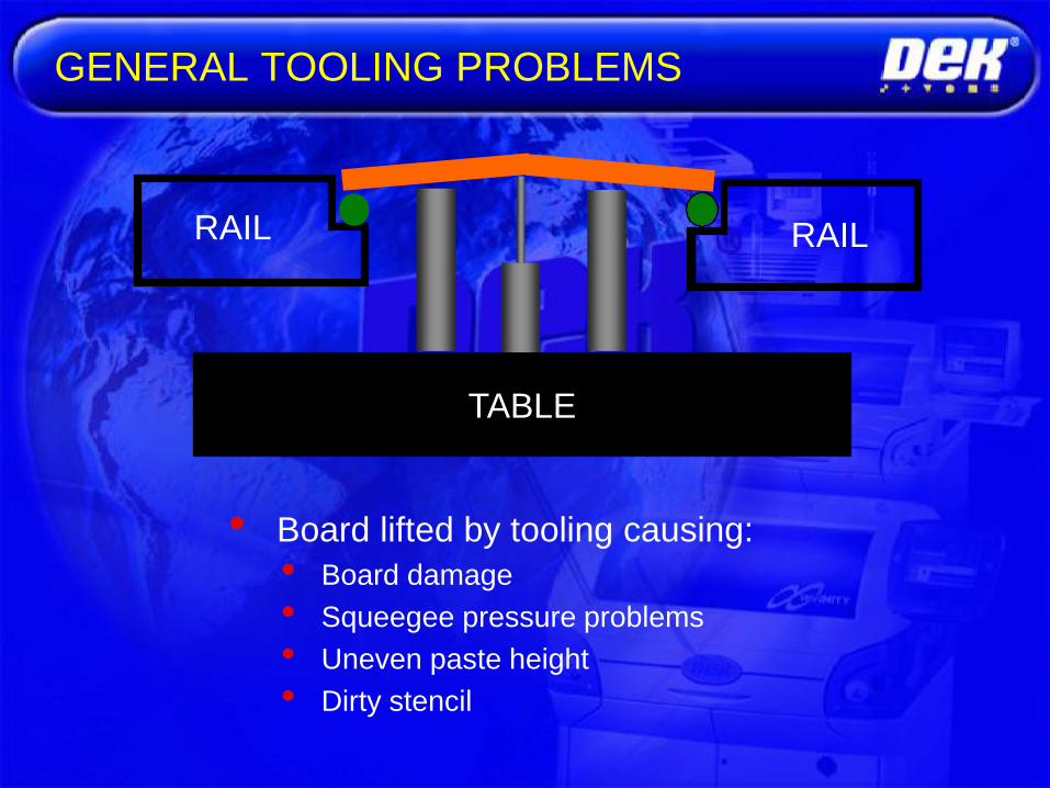
• Board lifted by tooling causing:
• Board damage
• Squeegee pressure problems
• Uneven paste height
• Dirty stencil
TABLE
RAIL RAIL
GENERAL TOOLING PROBLEMS
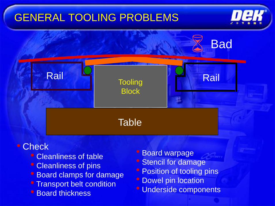
GENERAL TOOLING PROBLEMS
• Check• Cleanliness of table
• Cleanliness of pins
• Board clamps for damage
• Transport belt condition
• Board thickness
Table
Rail Rail
Bad
Tooling
Block
• Board warpage
• Stencil for damage
• Position of tooling pins
• Dowel pin location
• Underside components

Printability
• Accuracy and repeatability of paste deposits
• Acceptance criteria include
• Deposited paste weight from print to print should not exceed
10%
• Deposit height should have a tolerance of 1 mil from deposit
to deposit within a print
• Uniform coverage without tailing or separation

Print Gap
• The distance maintained between the
screen (or stencil) and the workpiece
• Also known as “snap-off”
• The stencil or screen lifts from the paste
deposits after the squeegee travels over
and fills the aperture

Gasketing
• The seal formed between the stencil or screen and
the substrate to be printed
• Good print definition and minimal bleed-out

Print Mode
• On-Contact• More accurate print
• Slow snap-off speed
• Off-Contact• Stencil kept 1-2 mil away from surface
• Local gasketing from squeegee pressure
• Used with screens to prevent smearing in flood mode

Print Speed
• Paste should roll for good print definition
• Downward component into apertures from roll provides even print
• Too fast a squeegee speed will
cause material to slide across
surface
• Material will lack the vertical
component and not fill apertures
properly, leading to inconsistencies in printing
• Balance throughput demands vs. aperture
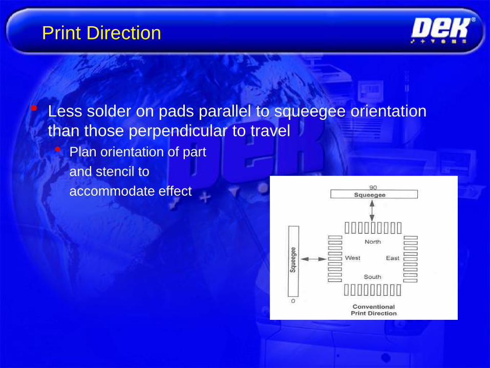
Print Direction
• Less solder on pads parallel to squeegee orientation
than those perpendicular to travel
• Plan orientation of part
and stencil to
accommodate effect

Transfer Efficiency
• The ratio of the volume of paste actually
deposited versus the volume of the stencil
aperture
• Round apertures generally have a higher
transfer efficiency than rectangular apertures

Process Window
• Affected by solder volume and coplanarity

Start at 0.5 kg pressure per 1 inch of squeegee
Adjust print speed to suit cycle time requirement
Print gap = 0 (no snapoff)
Separation speed usually not critical parameter.
Process window for SMT can tolerate print
speeds between 10 and 100mm/sec for reputable
solder pastes.
Rules of thumb:
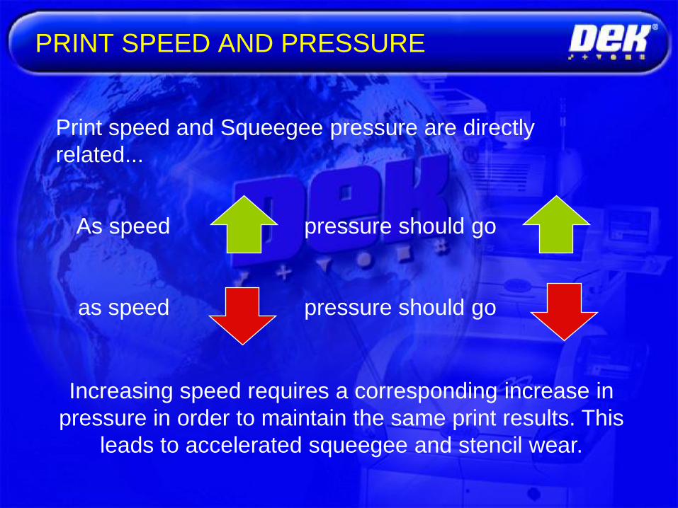
As speed pressure should go
as speed pressure should go
Increasing speed requires a corresponding increase in
pressure in order to maintain the same print results. This
leads to accelerated squeegee and stencil wear.
Print speed and Squeegee pressure are directly
related...
PRINT SPEED AND PRESSURE

• Separation speed
• The speed at which the board separates from the
stencil
• Adjust when deposits look conical or „Dog Eared‟
• This value effects print cycle time
• Separation distance
• The distance the board travels at the set separation
speed
• Keep to the minimum value required
• Faster separation speed, smaller distance required
SEPARATION SPEED AND DISTANCE
EXAMPLES BEYOND OUR DIRECT CONTROL
• TEMPERATURE (OPENING COVERS)
• HUMIDITY (OPENING COVERS)
• LIGHT (DAY TO NIGHT)
• HUMANS (BIGGEST PROBLEM)
• BOARD QUALITY
• “HEARTBEAT” IF LINE GOES DOWN

Constant temperature
Constant humidity
MACHINE ENVIRONMENT
Is the environment in control

• Temperature Control Unit
• Operator set
• ± 8º C from ambient
• Maintains to within ± 1º C
• Amber then Red beacon indications
• Audio alarm
•
TEMPERATURE CONTROL
COMMON PRINT PROCESS FAULTS


Standard paper roll under stencil cleaner
Wet, Vac, Dry modes
Controllable travel speed, number of passes,
vacuum level, cleaning interval.
Cleanroom grade paper available.

Alternative disposable porous foam cassette
cleaning system. Ultrasonic assisted systems
also offered. Topside cleaning uncommon.

Stencil bottomside contamination
Too many prints before bottomside cleaning.
Squeegee pressure too high.
Inadequate board support.
Poor stencil to board gasket.

Stencil bottomside contamination
…could be caused by circuit board topography.
i.e. traces, non uniform pad finish (HASL), solder
mask thickness / misregistration.

Result of printing on a perfect surface
Print #12
No stencil cleans between any prints.

• Squeegee pressure or
ProFlow pressure too low
• Separation speed too high
• USC set-up adequate
• Paste knead set-up
• Paste condition
STENCIL BLOCKAGE
Causes:

• Print/ProFlow pressure too high
• Alignment correct
• Print deposits greater than 1
• USC set-up adequate
• Paste knead too frequent
• Paste condition
STENCIL SMEAR
Causes:

• Print/ProFlow pressure
• Too many print deposits
• USC set-up
• Paste knead set-up
• Paste condition
• Stencil condition
BRIDGING
Causes:

• Print speed
• Print/ProFlow pressure
• Print deposits sufficient
• Separation speed
• Stencil blockage
• See next slide….
INSUFFICIENT PASTE
Causes:

• USC set-up
• Paste knead set-up
• Print speed too high
• ProFlow piston pressure toolow
• stencil wet after cleaning
• Wet or dirty boards
• No ProFlow stencil support
• Separation speed setincorrectly ...
INSUFFICIENT PASTE (CONTINUED)
Causes:
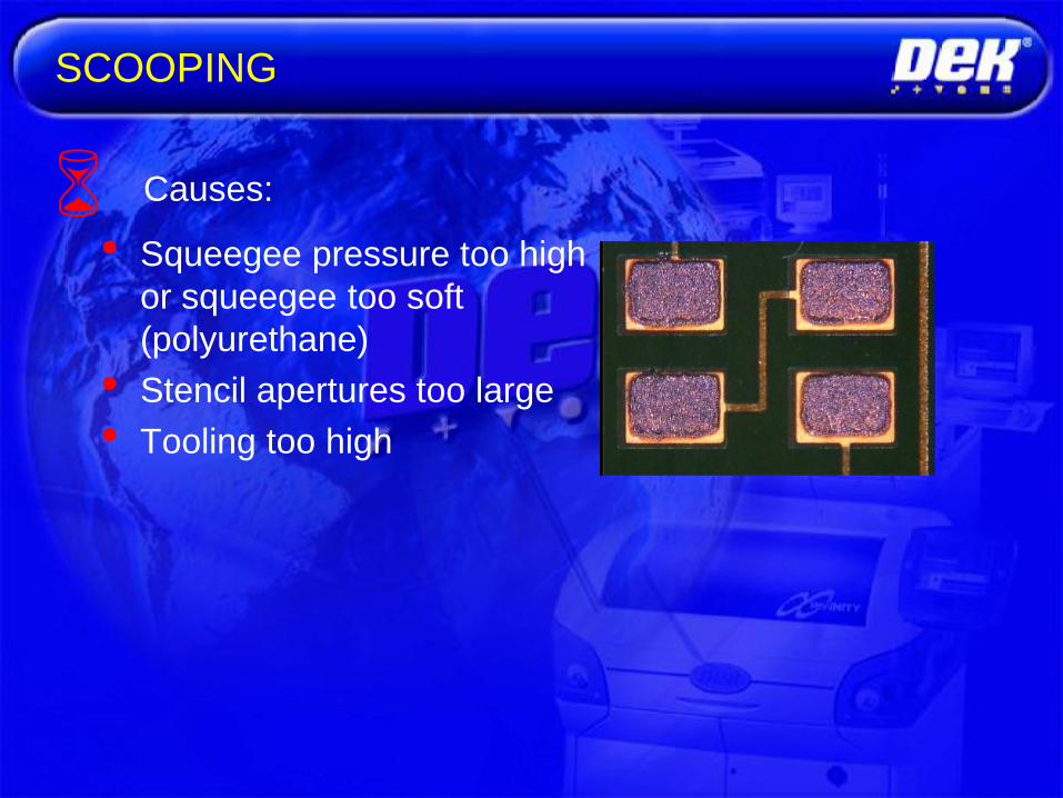
SCOOPING
• Squeegee pressure too high
or squeegee too soft
(polyurethane)
• Stencil apertures too large
• Tooling too high
Causes:

MISSING EDGE
• Squeegee/ProFlow
pressure too high
• ProFlow print speed too
low
• Tooling incorrect
Causes:

EXCESSIVE PASTE
• Squeegee ProFlow
pressure too high
• ProFlow print speed too
low
• Lack of tooling support
Causes:

• Fiducial set-up
• Correct offsets
• Alignment weighting
• Board to stencil mismatch
• Board stretch
• Machine calibration
ALIGNMENT
Causes:

• Clean edges
• Flat on top
• Height = Stencil Thickness
• Good Alignment
• No Flux Bleed ...
PERFECT PRINT
Goal: