Embed Size (px)
Citation preview
SC I ENCE ROBOT I C S | R E S EARCH ART I C L E
SOFT ROBOTS
1Biorobotics Laboratory, Department of Mechanical and Aerospace Engineering,Seoul National University, Seoul 08826, Korea. 2Institute of Advanced Machinesand Design, Seoul National University, Seoul 08826, Korea. 3Soft Robotics Re-search Center, Seoul National University, Seoul 08826, Korea. 4Bio-Inspired DesignLaboratory, Department of Mechanical and Automotive Engineering, Seoul Na-tional University of Science and Technology, Seoul 01811, Korea.*These authors contributed equally to this work.†Corresponding author. Email: [email protected]
Kim et al., Sci. Robot. 3, eaar2915 (2018) 14 March 2018
Copyright © 2018
The Authors, some
rights reserved;
exclusive licensee
American Association
for the Advancement
of Science. No claim
to original U.S.
Government Works
D
An origami-inspired, self-locking robotic arm that canbe folded flatSuk-Jun Kim,1,3* Dae-Young Lee,1,2,3* Gwang-Pil Jung,4 Kyu-Jin Cho1,2,3†
A foldable arm is one of the practical applications of folding. It can help mobile robots and unmanned aerialvehicles (UAVs) overcome access issues by allowing them to reach into confined spaces. The origami-inspired designenables a foldable structure to be lightweight, compact, and scalable while maintaining its kinematic behavior.However, the lack of structural stiffness has been a major limitation in the practical use of origami-inspired designs.Resolving this obstacle without losing the inherent advantages of origami is a challenge. We propose a solution byimplementing a simple stiffeningmechanism that uses an origami principle of perpendicular folding. The simplicity ofthe stiffening mechanism enables an actuation system to drive shape and stiffness changes with only a single electricmotor. Our results show that this design was effective for a foldable arm and allowed a UAV to perform a variety oftasks in a confined space.
own
by guest on February 3, 2020
http://robotics.sciencemag.org/
loaded from
INTRODUCTIONFolding is a long-standing and effective solution for space-saving prob-lems in both natural and artificial systems (1–4). A foldable roboticarm is an example of the application of folding in artificial systems,and it can help mobile robots and unmanned aerial vehicles (UAVs)to overcome access issues in difficult environments by allowing themto reach into confined spaces. Foldable or deployable arms can beimplemented using various methods including rigid links withconventional joints (5, 6), cylindrical components or bands wrappedaround a reel (7–11), and origami-inspired designs (7, 12–14).
Origami-inspired design enables a foldable structure to be lightweight,compact, and scalable while maintaining kinematic behavior because itcan replace mechanical components with a pattern of stiff facets andflexure hinges. This unique property makes origami-inspired designwidely applied as a method to fabricate robots at various scales andfor a variety of applications (13–25). However, the lack of structuralstiffness has been a major limitation in the practical use of origami-inspired designs. Ensuring adequate structural stiffness without losingthe inherent advantages of simple and lightweight origami structure is achallenging problem. Bistable origami patterns (26, 27), shape memorypolymer (SMP) stiffening (25), layer jamming (28, 29), and chemicalstiffening methods (7) have been suggested for stiffening mechanismfor origami structures.
Providing lightweight and compact actuation for origami structureis another important issue. Actuation of origami-inspired design can beachieved by either direct (generate a torque at each fold line directly) orindirect (apply a force to the entire structure) ways (30). The directmethod generally allows the structure to create versatile motions butwith high system complexity. In contrast, the indirect method allowsthe actuation system to be simple but limits a variety of motions. Shapememory alloys (SMAs) (20–24, 30–33) and SMPs or shrinking films(16, 17, 30, 34, 35) have been applied for direct actuation method, andpneumatic force (7, 12) and tendon-driven mechanisms (13–15, 25)have been applied for indirect actuation method.
In this study, we suggest an origami-inspired self-locking foldablerobotic arm with a tendon-driven actuation system. We used origami-inspired design to achieve a lightweight and ahigh extension to compres-sion ratio and devised a design method to build a stiffening mechanismthat works with multistep folding actuation. Our stiffening mechanismrelies on an origami principle of perpendicular folding: Two perpendic-ular fold lines generate a singularity that constrains each fold line’sdegrees of freedom. This mechanical locking process can substantiallyincrease the stiffness in the desired direction and is easily reversed be-cause it is a folding process. Restricting the degrees of freedom usingorthogonal movements is a widely used method of locking in con-ventional mechanisms such as door locks. However, unlike the jointswith precisely determinedmovement seen in conventionalmechanisms,the joints of origami structures are created by flexiblematerials and allowundesirablemovement. Thus, it is necessary to design the folding patternwhile keeping in consideration that the flexibility of the fold line can leadto unexpected problems, such as stiffness reduction.
Actuators usually have a high weight cost, which can be problematicfor mobile applications. We implemented a lightweight and compactactuation system that is driven by a single electric motor. This tendon-driven mechanism can actuate both the structure folding and the lockingmechanismwith a single tendon. The lockingmechanismmakes the struc-ture easily unlocked by the tendon force while withstanding external forcesin the locked mode. Friction was minimized along the tendon path to en-hance force transmissionandreducedraggingduringantagonistic actuation.
The proposed foldable arm is composed of seven foldable modulesassembled in series, and we applied the arm to a UAV with an end ef-fector such as a gripper or a camera. The arm allows theUAV to be usedto retrieve a target object located within a deep, narrow space and toaccess locations that are difficult or impossible for a UAV to approach(Fig. 1). The proposed armweighs 258.6 g, including its actuators.Whenfully folded and stowed, it is 40mm in length, and it can be extended upto 700 mm. Testing reveals that a foldable module using the lockingmechanism is 5 times more resistant to bending and 200 times moreresistant to compression compared with a module without lockers.
RESULTSFlat foldable arm design with a locking mechanismThemain objective of this studywas to design a robotic arm that is fold-able to a compact size and has sufficient stiffness. Many researchers
1 of 10

SC I ENCE ROBOT I C S | R E S EARCH ART I C L E
by guest on February 3, 2020
http://robotics.sciencemag.org/
Dow
nloaded from
have studied flat foldable origami pattern design, and there are severalorigami design candidates for a foldable arm (12–14, 19, 36–38). Fur-thermore, not only flat foldability but also sufficient stiffness and asmall footprint are required to apply an origami-inspired structure to arobotic arm.
Complex folding patterns are commonly used to create flat, foldable,origami structures that are compact and have a small footprint; however,the structure weakens as the number of fold lines increases. A modulardesign can be a simple solution to the problem because modules can bestacked to reduce the footprint without substantially increasing thecomplexity of the structure. In addition, using a modular design makesit easy to expand and modify the whole structure.
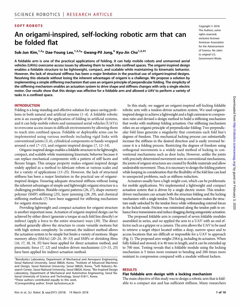
In addition, the modular design needed to have reduced degrees offreedom so that the structure could use simple actuation. To achievethis, we used a Sarrus linkage because it generates one degree of freedomin linear motion, which is the simplest possible closed linkage chain, tothe best of our knowledge. The Sarrus linkage in this study consisted of atop square, a bottom square, and four chains. Each chainwas connectedto each side of the square and consisted of two links and three joints.The lengths of each link were identical, which allowed the structure tobe flat and foldable (Fig. 2, A to C).
Foldable structures can be deformedundesirably by external forces—meaning that a structure’s stiffness must be high enough to meet therequirements associated with different tasks; it should or should notbe folded to suit the needs of different situations. For this application,
Kim et al., Sci. Robot. 3, eaar2915 (2018) 14 March 2018
the arm should be rigid in its deployed state but not in its folded state.In addition, configuration of the fold line is another important designfactor.Most origami-inspired foldable structures use flexiblematerialsto generate fold lines. The widths of the fold lines are generallydetermined by the thickness of the facet material. When the fold linewidth is excessive, the rigidity of the entire structure is greatlyweakened.It is then essential to minimize fold line width when the structure needsto have high rigidity.
Implementation of a stiffening mechanism was done by adjustingthe shape of the Sarrus linkage and adding an extra facet called a locker(fig. S8). The locker had no fold lines along the stiffening direction andwas wedged inside the structure to restrict the mobility of the Sarruslinkage (Fig. 2E). In its locked mode, the module was fully deployedand the lockers were locked in place until the lockers made contact withthe U1-B1 facet (Fig. 2D). To prevent the module from folding, thelockers were wedged between the top and bottom plates in the lockedposition. Decoupling mode change from the occurrence of externalforces is also a necessary consideration due to an external force’spotential to compromise the structural stability of the module. Wedecoupled these two conditions by applying the principle of perpendic-ular folding—if two fold lines are perpendicular, they generate asingularity that decouples their ability to simultaneously fold becauseonly one fold line can be folded along at a time; this mode change onlyoccurs when all facets are in the same plane. From Fig. 2, this concept isapplied to the fold line of the locker joint (m) and its perpendicular
Fig. 1. The foldable robotic arm enabled UAVs to perform tasks that could not be performed otherwise. (A) A UAV equipped with the self-locking foldablerobotic arm was tested outdoors. (B) A foldable arm could be folded into a compact volume and deployed on command. The arm equipped with an adequate endeffector could grasp an object or inspect inside a narrow, deep space. (C and D) Examples of tasks that could be performed with the foldable arm. The UAV couldinspect locations that are difficult to access, such as underwater and spaces between branches. Furthermore, the foldable arm could allow the UAV to obtain samplesfrom crevices in rugged terrain.
2 of 10
SC I ENCE ROBOT I C S | R E S EARCH ART I C L E
by guest on February 3, 2020
http://robotics.sciencemag.org/
Dow
nloaded from
counterpart joints (p-r) that constitute the Sarrus linkage. Therefore, theforce required to rotate the lockers was perpendicular to the force re-quired to fold the module. In contrast, when themodule was in its fold-able mode, the lockers are unlocked from the U1-B1 facet and wereoverlapped with U2 as shown in Fig. 2F.
The foldable module has three variables: l, length of one side of thetop and bottom square; h, height of the module; and w, width of the
Kim et al., Sci. Robot. 3, eaar2915 (2018) 14 March 2018
locker. In the fabricated modules, l, h, and w were 40, 100, and 16 mm,respectively. A single module weighed 27.5 g and could withstandcompressive forces over 15 kg-f. The modules were fabricated by amultimaterial planar fabrication method (15), which used a largedifference in stiffness between the facet and fold line materials andenabled easy construction of the linkage structure. Details of the fabri-cation method are provided in Materials and Methods.
Fig. 2. Foldable module with locking mechanism. (A to C) Foldable structure using Sarrus linkage. (D to F) Locking mechanism by adjusting the shape of the Sarruslinkage and adding an extra facet. (A) Deployed state. The Sarrus linkage with four chains assumes a square column shape when deployed. (B) Transition state. (C) Folded state.The Sarrus linkage can be folded flat when the two links are of the same length. (D) In the locked mode, the fold line p to r cannot be folded because the lockers are inthe locked position. The locking mechanism constrained the degrees of freedom of the foldable module and increased its stiffness. (E) Locker in the transitionalposition. (F) In the foldable mode, the lockers are in the unlocked position. The lockers were unlocked from the U1-B1 facet and overlapped with U2. Because allfacets were in the same plane, the fold line p to r could be folded. Upper figures depict trimetric views of the module. The figure shows only the frontal two chains forsimplicity. Lower figures depict a top view of the module.
3 of 10
SC I ENCE ROBOT I C S | R E S EARCH ART I C L E
http://robotics.scienD
ownloaded from
Design of the actuation system driven by a singleelectric motorTo ensure the lightweight advantage of themodular structure, which is ahighly desirable attribute formobile applications, we aimed to design anactuation system that uses theminimumnumber of actuatorswhile alsobeing reliable and repeatable. Various low-profile smart materials suchas SMAs and electroactive polymers have been used to successfullyactuate origami structures by directly applying a torque to fold lines(30). These direct actuation methods provide high degrees of freedom,but their reliability and robustness are not superb. Pneumatic actuationhas been used with origami structures, and it is an effective method fortransmitting force from a single actuation source to a whole body (12).However, it requires an air pump, which is usually heavier than anelectric motor. In this study, we propose a tendon-driven actuationsystemwith a single electric motor, which can be lightweight and canbe applied to scalable structures.
Folding is used in two ways in the proposed arm: for structurefolding and for the locking mechanism. These two different foldingprocesses should be driven sequentially, and they require forces thatare perpendicular to each step. Because tendon-driven actuation with asingle electric motor normally provides actuation with one degree offreedom, driving two folding steps with a single tendon is a challengingproblem. Structure folding of serially assembled Sarrus linkages allowsa single tendon to change the overall structure with high scalability—the number of modules does not affect the complexity of actuation.However, the locking mechanism requires additional actuation. Touse a single tendon to exert force in two different directions, we need todistort the tendon path for each locker, which induces tendon friction
Kim et al., Sci. Robot. 3, eaar2915 (2018) 14 March 2018
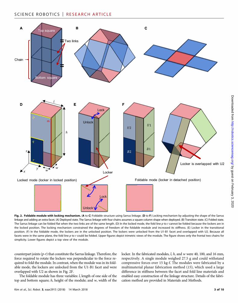
and lowers the force transmission efficiency. Thus, to solve this prob-lem, we designed a variable tendon path consisting of a curved slit pathon the lockers. The slit design made it possible to exert a large force forthe locking mechanism but also allowed the tendon to move along theslit to reduce path distortion during the structural change.
Details of the actuation mechanism are shown in Fig. 3. Figure 3Adescribes a module with two adjoining chains at the nth layer from thetop. The tendon path consisted of two holes and one slit. Two holes,An
andOn, were located on the top and bottom squares, respectively, and aslit connecting points Bn andCnwas located on the lockers. To facilitatetendon connection between modules, we placed An and On on the topand bottom squares, and these points were assumed to be located at thecenter of each side. We designed the tendon to enter the modulethrough hole An from the (n − 1)th layer, pass through the slit on alocker, and come out through hole On to the (n + 1)th layer, as shownin Fig. 3. When the lockers were in the locked position, two kinds offorces were applied to the module by pulling the tendon from upside(regarding the top square as fixed and On as the end of the tendon).A force (FL) drove the lockers to rotate around the joint and to be un-locked from the U1-B1 facet, and a compressive force parallel to the zaxis (FZ) drove the module into the folded state. Because lockers con-strained the module’s degrees of freedom and withstood FZ, themodule could not be folded andonly the lockers could be rotated.Whenthe lockers were unlocked and overlappedwithU2, themodule regainedits degrees of freedom and could be folded by the tension, enabling se-quential folding by a single tendon. In the case of deploying themodule,a tensile force in the z-axis direction was required. A flexible tendoncannot push the module or the lockers by unwinding the pulley, so
by guest on February 3, 2020
cemag.org/
Fig. 3. Tendon path design of the module. Tendon friction was minimized to increase force transmission and not to constrain antagonistic actuation. The foldingprocess is in order of A to C. The deployment process follows the reverse order. (A) Tendon path when the module is deployed and the lockers are locked. (B) Locker intransitional position. When the tendon was pulled upward to fold the module, Fz and FL were applied to the module. (C) Tendon path when the module is being folded.During folding, the tendon moved along the slit from Bn to Cn (yellow double-headed arrow). During deployment, the tendon stayed at Cn owing to the bent slit. Upperfigures depict trimetric views of the module. The figure shows only two frontal chains for simplicity. Lower figures depict a top view of the module.
4 of 10

SC I ENCE ROBOT I C S | R E S EARCH ART I C L E
elastic rubber bands and magnets were used for antagonistic actuation.The elastic bands were installed between chains that are facing each other(Fig. 3C), and the magnets were installed on the lockers and adjoiningU1-B1 facets (fig. S8).When the tendon was unwound, themodule was
Kim et al., Sci. Robot. 3, eaar2915 (2018) 14 March 2018
http://roboticD
ownloaded from
deployed via the elastic force of the rubber bands and the force ofgravity, and when the module was fully deployed, the lockers were pas-sively rotated and locked by magnetic force. A detailed explanation onhow to route the tendon path design to reduce friction is presented inthe Supplementary Text.
Performance study on the module designStiffening via folding is a key feature of this paper. Therefore, mechanicalproperties, such as the stiffness and the maximum load capacity, wouldbe a crucial standard for the evaluation of the mechanism’s structuralperformance. However, it is difficult to use analytical methods to inves-tigate the effects of the module’s geometric design parameters onmechanical properties, owing to complex material composition andgeometry. Rather, this study used empirical methods to investigatethe relationship between the design parameters and the mechanicalproperties of the structure.
A cube-shaped module with a side length of 40 mm and a lockerwidth of 8 mm was selected as a reference, and the experiments werecarried out by changing specific design parameters, whereas the otherswere fixed as reference values to see how they would affect themechanical properties of the structure. Normalized design parameterswere defined as follows: l, normalized side length; h, normalized height;w, normalized locker width. l and hwere normalized by the side lengthof the referencemodule, 40mm, and wwas normalized by l, the lengthof one side of the top and bottom square, to identify the scale effect ofl when maintaining the ratio of the locker. Performance tests were
Fig. 4. Types and directions of external forces on the module and coordina-tion representing the movement of the locker. In the performance study, weanalyzed the mechanical responses of the module according to the change of thedesign parameters in the compression direction and the bending direction shownin the figure. Because the relative motion of the lockers is an important factor indetermining the mechanical response, a coordinate system shown in the figure isused to describe the motion of the lockers.
by guest on February 3, 2020
s.sciencemag.org/
Fig. 5. Results of the performance study experiment: Compression (sample size: n = 5). (A) Compressive stiffness of the module when l was changed. (B) Compressivestiffness of the module when hwas changed. (C) Compressive stiffness of the module when l and hwere both changed. (D) Compressive stiffness of the module when w waschanged. (E) Maximum compressive load when l was changed. (F) Maximum compressive load when h was changed. (G) Maximum compressive load when l and h wereboth changed. (H) Maximum compressive load when w was changed. Blue plots on the figures represent bending stiffness trend according to the general beam theory. Redplots on the figures represent the trend of results that are driven by least-squares methods. a and b are exponents of l and h, respectively. Whiskers are extended to 1.5 timesof interquartile range (IQR) from the edge of the box; IQR is difference between upper and lower quartile. Asterisks indicate outliers that are beyond the whiskers.
5 of 10
SC I ENCE ROBOT I C S | R E S EARCH ART I C L E
http://roboticD
ownloaded from
performed to examine the stiffness and the maximum load capacityunder compression and bending load. Because the mechanical prop-erties from tensile loading were determined bymaterial performancerather than structural characteristics, we excluded tensile testingfrom the analysis. The material properties of the fold line materialare attached to the Supplementary Materials.
Themodule response to compressive loading is shown in Fig. 5. Theexpected trend curve from conventional solid mechanics and the actualtrend curve estimated with the least-squares method are indicated byblue and red lines, respectively. According to the general beam theory,compressive load resistance is proportional to l and inversely propor-tional to h. However, Fig. 5A indicates that the change in compressivestiffness gradually decreased as l increased. Figure 5B rather indicates areverse trend compared with the expected results. As the normalizedheight, h , increased, the compressive stiffness increased. These trendscan also be seen in Fig. 5C, where the stiffness increasedwhen both l andh changed simultaneously. For the locker width, the change in compres-sive stiffness gradually decreased as w increased, as shown in Fig. 5D.We presumed that this is because the stiffness is mainly determined byundesirable rotation of the facets caused by flexibility of the fold lines,not the deformation of the facets.
When compressionwas exerted on the structure, the locker rotatedin the y and z directions, as indicated in Fig. 4. The shape of the lockerwas an important factor in determining the angle of rotation. Whenthe locker width was too small, it rotated in both the y and z directions(l = 0.5 in Fig. 5A). When w was widened as l increased, the stiffness
Kim et al., Sci. Robot. 3, eaar2915 (2018) 14 March 2018
rapidly increased because a locker with large width can prevent ro-tation in the y direction. However, the increase in stiffness rapidlydeclined, because the increase of w did not prevent the rotation inthe z direction. In the case of h, the locker got longer in the fold linedirection when h increased. This elongated shape caused the lockerto rotate less within the same fold line width, strengthening thestructural stiffness.
Themaximum load wasmeasured at the moment when themodulefailed. This occurredmost frequently when the locker popped out of themodule. Locker poppingwas difficult to quantify but could be describedby behavior similar to the locker’s stiffness analysis. When the lockerwidth was short, the locker had a high possibility to pop out becausethe locker rotated in the y and z directions. Therefore, a wider lockerwas preferred to withstand high compression loading. Similar to thestiffness case, the rate of increasing the stiffness rapidly declined asthe locker width increased over a certain length. The general responseto maximum compressive loading showed similar aspects with theresults of compressive stiffness, as shown in Fig. 5 (E to H).
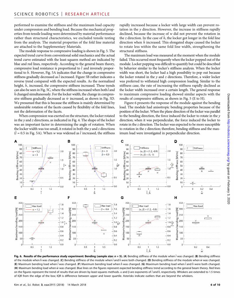
Figure 6 presents the response of the module against the bendingload. The module had anisotropic bending properties because of theposition of the locker.When the plane direction of the locker was parallelto the bending direction, the force induced the locker to rotate in the ydirection; when it was perpendicular, the force induced the locker torotate in the z direction. The locker was expected to bemore susceptibleto rotation in the z direction; therefore, bending stiffness and the max-imum load were investigated in perpendicular direction.
by guest on February 3, 2020
s.sciencemag.org/
Fig. 6. Results of the performance study experiment: Bending (sample size: n = 5). (A) Bending stiffness of the module when l was changed. (B) Bending stiffnessof the module when hwas changed. (C) Bending stiffness of the module when l and hwere both changed. (D) Bending stiffness of the module when w was changed.(E) Maximum bending load when l was changed. (F) Maximum bending load when h was changed. (G) Maximum bending load when l and h were both changed.(H) Maximum bending load when w was changed. Blue lines on the figures represent expected bending stiffness trend according to the general beam theory. Red lineson the figures represent the trend of results that are driven by least-squares methods. a and b are exponents of l and h, respectively. Whiskers are extended to 1.5 timesof IQR from the edge of the box; IQR is difference between upper and lower quartile. Asterisks indicate outliers that are beyond the whiskers.
6 of 10
SC I ENCE ROBOT I C S | R E S EARCH ART I C L E
According to the general beam theory, the bending stiffness shouldbe proportional to the cube of l and inversely proportional to the cube ofh. The actual trend was different, similar to the response by the com-pressive load. In Fig. 6A, the bending stiffness increased as l got longer,because the Sarrus linkage has zero degrees of freedom in the bendingdirection, but not as high as expected due to stiffness loss caused bylocker rotation. In the case of h in Fig. 6B, the structure showed muchhigher stiffness than expected. It can be inferred that the stiffnessincreased as the rotation of the locker was reduced because the locker’slength in fold line direction became longer.
The maximum bending load appeared to be determined by howmuch the locker rotates, similar to the compressive response. The ex-perimental results show that the stiffness and themaximum load tended
Kim et al., Sci. Robot. 3, eaar2915 (2018) 14 March 2018
to be similar to the bending response shown in Fig. 6 (E to H). For aparticular length requirement for the foldable arm, it is advantageous toreduce the total number of modules and instead increase the length ofindividual modules.
As a result of the design parameter studies, it was confirmed that alarge h improved performance, but l did not improve performance asexpected, considering volume and weight increases. w improvedperformance drastically up to a certain length but did not show asubstantial performance improvement with further increase. Fromthis, module parameters were determined most effective when l, h,and w were 40, 100, and 16 mm, respectively for this application. Adetailed report of the results from the performance experiment is in-cluded in the Supplementary Materials.
by guest on February 3, 2020
http://robotics.sciencemag.org/
Dow
nloaded from
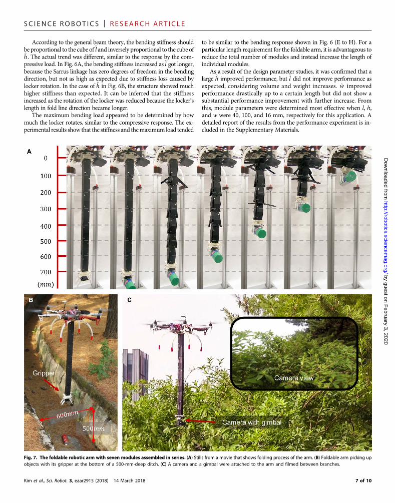
Fig. 7. The foldable robotic arm with seven modules assembled in series. (A) Stills from a movie that shows folding process of the arm. (B) Foldable arm picking upobjects with its gripper at the bottom of a 500-mm-deep ditch. (C) A camera and a gimbal were attached to the arm and filmed between branches.
7 of 10
SC I ENCE ROBOT I C S | R E S EARCH ART I C L E
by guest on February 3, 2020
http://robotics.sciencemag.org/
Dow
nloaded from
The foldable arm in applicationThe foldable armwas validated through indoor and outdoor tests. In theindoor test, the arm was deployed and folded repeatedly, and variousobjects were gripped with the buckling gripper (fig. S10 and movieS5; see Supplementary Text) (39). The buckling gripper was redesignedto be fully foldable and provided many contacts with even contactforces, which enabled adaptive gripping. As shown in Fig. 7A, the700-mm arm was able to fold itself to a 40-mm height, achieving anextension-to-compression ratio of 17.5:1. The stills in Fig. 7A werecaptured at intervals of 8 s. It took 40 s for the arm to fully fold itself(movie S3).
In the outdoor test, first, the UAV carried the folded arm over aditch, and the arm fully deployed itself. The UAV then lowered itselfenough to allow the gripper to pick up an object at the bottomof the ditchwithout entering the ditch itself (Fig. 7B and movie S4). The ditch wasnarrow enough to pose a danger to the UAV: The ditch was 600 mmwide, and the UAV’s diameter was 550 mm. The arm successfullyfolded itself and stowed itself away in the landing gear during takeoffand landing. Second, the arm was equipped with a gimbal (3DIII metalgimbal TL3T01, Tarot) and a GoPro camera (GoPro Hero 3+, GoPro)to performvideotaping near trees and among tree branches, as shown inFig. 7C and movie S4. The UAV used for outdoor tests of the foldablearm was the DJI F550 frame kit (F550 ARF KIT, DJI).
DISCUSSIONIn this study, we designed an origami-inspired self-locking foldablerobotic arm with tendon-driven actuation system. Using the origami-inspired design allowed us to develop lightweight modules that are100 mm in height and weighs 27.5 g. We also implemented a self-locking mechanism using the principle of perpendicular folding. Wemeasured the maximum bending load and bending stiffness of the
Kim et al., Sci. Robot. 3, eaar2915 (2018) 14 March 2018
module and determined that modules with lockers are about 5 timesstiffer against bending and 200 times stiffer against compression thanthose without lockers. We used seven modules to assemble the foldablearm and attached a UAV to one end of the arm and a gripper or a gim-bal and a camera to the other. The resulting assembly was validated andperformed a variety of tasks.
The foldable arm endows UAVs with the ability to perform tasks inareas too small for aUAV to enter. For example, equipping the armwitha gimbal and a camera would enable a UAV to inspect small chimneysand narrow-bore pipes. The foldable arm can also allow UAVs to per-form tasks in areas where the terrain makes a safe landing impossible,such as obtaining samples from crevices in rugged terrain. Future workcould design a foldable arm that extends from the top of a UAV, whichwould enable such tasks as performing a visual inspection beneath abridge and perching on a structure to save energy. Mobile robots coulduse the foldable arm to perform tasks while exploring confined spaces,taking advantage of the foldable arm’s compact storage volume.
The arm in this study has several limitations that need to beovercome in future work. First is the length of the arm. Fabricatingthe arm longer by stacking more modules together also increased ten-don friction, which hindered its antagonistic actuation and preventedthe arm from operating properly. Module height could be increasedto overcome this problem, but doing so would increase the foldablearm’s footprint. It is impossible to completely eliminate tendon friction,but an active locking mechanism with extra actuation could be used toeliminate distortion of the tendon path and to accommodate increasesin the arm length. A second limitation is the stiffness of the arm. Struc-tural stiffness modeling is needed to find optimized variable sets, andthe weak intermodular assembly should be enhanced. The adhesivesand eyelets used to connect the modules did not guarantee firmmechanical bonding between modules (figs. S1 to S3). The weaknessof the intermodular assembly made the deployed arm unstable when
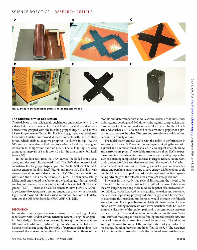
Fig. 8. Steps in the fabrication process of the foldable module.
8 of 10
SC I ENCE ROBOT I C S | R E S EARCH ART I C L E
the UAV flew fast. One possible solution is to fabricate the foldable armas a body instead of separate units, or a method for interlocking themodules could be devised. The final limitation is the arm’s limiteddegrees of freedom. Although UAVs have six degrees of freedom, thefoldable arm in this study could only pick up objects from a limitedrange of directions because it has no joints. To enable complex tasks,the arm needs to have more degrees of freedom. In future work, mod-ules with low-profile origami joints that are compact and lightweightcould be designed.
by guest on February 3, 2020
http://robotics.sciencemag.org/
Dow
nloaded from
MATERIALS AND METHODSFabricationTo fabricate the foldablemodule, we used amultimaterial planar fab-rication method (15) that was developed to build origami structuresby giving stiffness difference between facets and fold lines. Polyethyleneterephthalate (PET) film with thermal adhesive on one side (0.35 mm;ARO Tech) was chosen for the facets, and the ripstop fabric (0.2 mm;ARO Tech) was chosen as a compliant material for the fold lines. Thefollowing steps describe the process:
1) Sticky polyamide film (CT-1065, Coretec) was attached to theside of the PET film with no thermal adhesive (Fig. 8A).
2) Desired patternswere laser-cut (VLS 3.5, Universal Laser System)from two PET films and the ripstop, and excess material was removed(Fig. 8B).
3) The cut ripstop pattern was sandwiched between patterns cutfrom the PET films. Backlighting was used to align the patterns(Fig. 8C).
4) The sandwiched structure was pressed in an automated heatpresser (QM900A, QME-SYS) for 5 min at 110°C and 0.5 MPa to meltthe thermal adhesive so that the PET films and the ripstop could bebonded together (Fig. 8D).
5) After 10 min of cooling at room temperature below a steel plateand a 2-kg weight, the polyamide film was peeled off, and the ripstopfabric that protruded from the structure was removed (Fig. 8E).
6) Neodymium magnets were installed with tapes, and elasticrubber bands were installed. The module was assembled withtwo-sided tape and eyelets. The final model is shown in Fig. 8F.l, h, and w of the model are 40, 100, and 16 mm, respectively.
Most of the other structural parts were fabricated with a three-dimensional printer (uPrint SE Plus, Stratasys).
By assembling seven modules, the proposed arm was able to reachup to 700mmbelow theUAV andweighed 258.6 g, including actuationsystem. Detailed specifications of the prototype are written in table S2.In addition, a connector that assembles the arm and end effector wasdesigned to allow the gripper to be easily changed out for the gimbalwith attached GoPro camera. Spur-geared motors with encoders werechosen for actuating the arm and the gripper [RA-12WGM 02TYPE(6V) with 2channel Encoder, 298:1; D&J WITH Co. Ltd.]. ArduinoMicro and XBee S1 modules were chosen as the microcontroller andwireless communication device used to control the arm and the gripper.
ExperimentsFor the performance study experiment, we fabricated samples bychanging l, h, and w to analyze the independent effects of variableson model stiffness. As shown in fig. S11, four sets of samples wereprepared: (i) by changing l from 20 to 60 mm in 20-mm incrementswhile keeping w at 20% of l and h at 40 mm, (ii) by changing h from20 to 60 mm in 20-mm increments while keeping w at 20% of l and l
Kim et al., Sci. Robot. 3, eaar2915 (2018) 14 March 2018
at 40 mm, (iii) by changing both l and h from 20 to 60 mm in 20-mmincrements simultaneously while keeping w at 20% of l, and (iv) bychangingw from 0 to 40% of l in 20% increments while keeping l andh at 40mm. The sizes of magnets were chosen to be proportional to l.For each l from 20 to 40 to 60 mm, the diameter of the magnetschanged from 3 to 5 to 8 mm. The design of every sample fabricatedfor experiments was simplified; lockers were simplified to rectangularshape, and tendon pathswere removed.However, in the case of samplesfor robustness experiment in the Supplementary Materials, sampleswere fabricated just the same as the one used for the foldable arm.
For the bending test, we installed 4T acrylic plate inside and outsideof the samples at both ends of the module, and fixed end was bolted toan aluminum test bed as shown in fig. S6A. Shear force was exerted atthe free end of the module. The length of one side of acrylic plate thatwas installed inside themodule was set at 90% of l. For the compressiontest, the bottom square of themodule was bolted to the test bed, and thecompressive force was exerted to the module as shown in fig. S6B. Foreach sample, the stiffness of the module and maximum load that themodule could withstand were measured, and all experimental resultswere measured with a universal testing machine (model RB302,R&B) and a load cell (model UMM-K100, Dacell).
Because the module stiffness is highly nonlinear, linear approxima-tion was conducted to calculate the stiffness. We drew tangent linesthroughout the force-displacement graphs and chose the steepest slopeas the module stiffness. The displacement interval for calculating theslope was 1mm. In the case of measuring themaximum load, we chosethemaximum force value on the force-displacement graphs. Results aredepicted using a box plot format and Tukey-style whiskers.
SUPPLEMENTARY MATERIALSrobotics.sciencemag.org/cgi/content/full/3/16/eaar2915/DC1TextFig. S1. Results of performance experiment: Bending (sample size: N = 5).Fig. S2. Results of performance experiment: Compression (sample size: N = 5).Fig. S3. Results of performance experiment: Tensile stiffness (sample size: N = 5).Fig. S4. Results of performance experiment: Robustness (sample size: N = 3).Fig. S5. Force-displacement graph under compressive and bending loads.Fig. S6. Experimental setup.Fig. S7. Experimental setup for repeatedly folding the module.Fig. S8. Origami-inspired pattern design of the foldable module.Fig. S9. Schematics of the foldable module for tendon friction modeling.Fig. S10. The lightweight and compact buckling gripper.Fig. S11. Fabricated samples with different variable sets.Table S1. Variables for the foldable module assuming [l, h, w] = [40, 100, 16] (mm).Table S2. Specifications for the foldable arm.Table S3. Tensile test results of ripstop fabric.Table S4. Parameters chosen for the buckling gripper.Table S5. Experimental results of performance study experiment: Compression.Table S6. Experimental results of performance study experiment: Bending.Table S7. Experimental results of application performance experiment.Movie S1. Tendon-driven foldable module.Movie S2. Foldable module with locking mechanism.Movie S3. Foldable arm indoor test.Movie S4. Foldable arm outdoor test.Movie S5. Lightweight and compact buckling gripper.Reference (40)
REFERENCES AND NOTES1. D. S. A. De Focatiis, S. D. Guest, Deployable membranes designed from folding tree
leaves. Philos. Trans. A Math. Phys. Eng. Sci. 360, 227–238 (2002).2. J. F. V. Vincent, Deployable structures in nature: Potential for biomimicking. Proc. Inst.
Mech. Eng. C 214, 1–10 (2000).
9 of 10
SC I ENCE ROBOT I C S | R E S EARCH ART I C L E
by guest on February 3, 2020
http://robotics.sciencemag.org/
Dow
nloaded from
3. B. Kresling, Coupled mechanisms in biological deployable structures, in IUTAM-IASSSymposium on Deployable Structures: Theory and Applications (Springer, 2000),pp. 229–238.
4. E. Morris, D. A. McAdams, R. Malak, The state of the art of origami-inspired products: Areview, Proceedings of the ASME 2016 International Design Engineering TechnicalConferences and Computers and Information in Engineering Conference, Charlotte, NC, 21to 24 August 2016 (ASME, 2016).
5. C. M. Korpela, T. W. Danko, P. Y. Oh, MM-UAV: Mobile manipulating unmanned aerialvehicle. J. Intell. Robot. Syst. 65, 93–101 (2012).
6. V. A. Sujan, S. Dubowsky, Design of a lightweight hyper-redundant deployable binarymanipulator. J. Mech. Des. 126, 29–39 (2004).
7. M. Schenk, A. D. Viquerat, K. A. Seffen, S. D. Guest, Review of inflatable booms for deployablespace structures: Packing and rigidization. J. Spacecr. Rockets 51, 762–778 (2014).
8. J. Block, M. Straubel, M. Wiedemann, Ultralight deployable booms for solar sails and otherlarge gossamer structures in space. Acta Astronaut. 68, 984–992 (2011).
9. E. W. Hawkes, L. H. Blumenschein, J. D. Greer, A. M. Okamura, A soft robot that navigatesits environment through growth. Sci. Robot. 2, eaan3028 (2017).
10. T. Kuciński, T. Rybus, K. Seweryn, M. Banaszkiewicz, T. Buratowski, G. Chmaj, J. Grygorczuk,T. Uhl, Deployable manipulator technology with application for UAVs, in AerospaceRobotics II (Springer, 2015), pp. 93–103.
11. F. Collins, M. Yim, Design of a spherical robot arm with the spiral zipper prismatic joint,Proceedings of the 2016 IEEE International Conference on Robotics and Automation (ICRA),Stockholm, Sweden, 16 to 21 May 2016 (IEEE, 2016).
12. R. V. Martinez, C. R. Fish, X. Chen, G. M. Whitesides, Elastomeric origami: Programmable paper-elastomer composites as pneumatic actuators. Adv. Funct. Mater. 22, 1376–1384 (2012).
13. K. Zhang, C. Qiu, J. S. Dai, An extensible continuum robot with integrated origami parallelmodules. J. Mech. Robot. 8, 031010 (2016).
14. T. Liu, Y. Wang, K. Lee, Three-dimensional printable origami twisted tower: Design,fabrication, and robot embodiment. IEEE Robot. Autom. Lett. 3, 116–123 (2017).
15. D.-Y. Lee, S.-R. Kim, J.-S. Kim, J.-J. Park, K.-J. Cho, Origami wheel transformer: A variable-diameter wheel drive robot using an origami structure. Soft Robot. 4, 163–180 (2017).
16. S. Felton, M. Tolley, E. Demaine, D. Rus, R. Wood, A method for building self-foldingmachines. Science 345, 644–646 (2014).
17. S. Miyashita, S. Guitron, S. Li, D. Rus, Robotic metamorphosis by origami exoskeletons. Sci.Robot. 2, eaao4369 (2017).
18. G.-P. Jung, K.-J. Cho, Froghopper-inspired direction-changing concept for miniaturejumping robots. Bioinspir. Biomim. 11, 056015 (2016).
19. C. D. Onal, R. J. Wood, D. Rus, An origami-inspired approach to worm robots. IEEE/ASMETrans. Mechatron. 18, 430–438 (2013).
20. M. Noh, S.-W. Kim, S. An, J.-S. Koh, K.-J. Cho, Flea-inspired catapult mechanism forminiature jumping robots. IEEE Trans. Robot. 28, 1007–1018 (2012).
21. A. Firouzeh, J. Paik, Robogami: A fully integrated low-profile robotic origami. J. Mech.Robot. 7, 021009 (2015).
22. J.-S. Koh, E. Yang, G.-P. Jung, S.-P. Jung, J. H. Son, S.-I. Lee, P. G. Jablonski, R. J. Wood,H.-Y. Kim, K.-J. Cho, Jumping on water: Surface tension–dominated jumping of waterstriders and robotic insects. Science 349, 517–521 (2015).
23. J.-S. Koh, K.-J. Cho, Omega-shaped inchworm-inspired crawling robot with large-index-and-pitch (LIP) SMA spring actuators. IEEE/ASME Trans. Mechatron. 18, 419–429 (2013).
24. M. Boyvat, J.-S. Koh, R. J. Wood, Addressable wireless actuation for multijoint foldingrobots and devices. Sci. Robot. 2, eaan1544 (2017).
25. A. Firouzeh, J. Paik, An under-actuated origami gripper with adjustable stiffness joints formultiple grasp modes. Smart Mater. Struct. 26, 055035 (2017).
26. L. J. Wood, J. Rendon, R. J. Malak, D. Hartl, An origami-inspired, SMA actuated liftingstructure, Proceedings of the ASME 2016 International Design Engineering TechnicalConferences and Computers and Information in Engineering Conference, Charlotte, NC, 21to 24 August 2016 (ASME, 2016).
27. J. Kim, D.-Y. Lee, S.-R. Kim, K.-J. Cho, A self deployable origami structure with lockingmechanism induced by buckling effect, Proceedings of the 2015 IEEE International Conferenceon Robotics and Automation (ICRA), Seattle, WA, 26 to 30 May 2015 (IEEE, 2015).
Kim et al., Sci. Robot. 3, eaar2915 (2018) 14 March 2018
28. J. Ou, L. Yao, J. Steimle, R. Niiyama, H. Ishii, jamSheets: Thin interfaces with tunablestiffness enabled by layer jamming, Proceedings of the 8th International Conference onTangible, Embedded and Embodied Interaction, Munich, Germany, 16 to 19 February 2014(ACM, 2014).
29. Y.-J. Kim, S. Cheng, S. Kim, K. Iagnemma, A novel layer jamming mechanism withtunable stiffness capability for minimally invasive surgery. IEEE Trans. Robot. 29, 1031–1042(2013).
30. E. A. Peraza-Hernandez, D. J. Hartl, R. J. Malak Jr., D. C. Lagoudas, Origami-inspired activestructures: A synthesis and review. Smart Mater. Struct. 23, 094001 (2014).
31. J. K. Paik, R. J. Wood, A bidirectional shape memory alloy folding actuator. Smart Mater.Struct. 21, 065013 (2012).
32. E. Hawkes, B. An, N. M. Benbernou, H. Tanaka, S. Kim, E. D. Demaine, D. Rus,R. J. Wood, Programmable matter by folding. Proc. Natl. Acad. Sci. U.S.A. 107,12441–12445 (2010).
33. J.-S. Koh, S.-R. Kim, K.-J. Cho, Self-folding origami using torsion shape memory alloy wireactuators, Proceedings of the ASME 2014 International Design Engineering TechnicalConferences and Computers and information in Engineering Conference, Buffalo, NY, 17 to20 August 2014 (ASME, 2014).
34. M. T. Tolley, S. M. Felton, S. Miyashita, D. Aukes, D. Rus, R. J. Wood, Self-folding origami:Shape memory composites activated by uniform heating. Smart Mater. Struct. 23, 094006(2014).
35. Y. Liu, B. Shaw, M. D. Dickey, J. Genzer, Sequential self-folding of polymer sheets. Sci. Adv.3, e1602417 (2017).
36. T. A. Evans, R. J. Lang, S. P. Magleby, L. L. Howell, Rigidly foldable origami gadgets andtessellations. R. Soc. Open Sci. 2, 150067 (2015).
37. T. Tachi, One-DOF cylindrical deployable structures with rigid quadrilateral panels,Proceedings of the International Association for Shell and Spatial Structures (IASS)Symposium, Valencia, Spain, 29 September to 2 October 2009 (Editorial UniversitatPolitècnica de València, 2009).
38. T. Tachi, K. Miura, Rigid-foldable cylinders and cells. J. Int. Assoc. Shell Spat. Struct. 53,217–226 (2012).
39. G.-P. Jung, J.-S. Koh, K.-J. Cho, Underactuated adaptive gripper using flexural buckling.IEEE Trans. Robot. 29, 1396–1407 (2013).
40. M. Kaneko, T. Yamashita, K. Tanie, Basic considerations on transmission characteristics fortendon drive robots, Proceedings of the Fifth International Conference on AdvancedRobotics, 1991. ’Robots in Unstructured Environments’, 91 ICAR, Pisa, Italy, 19 to 22 June1991 (IEEE, 1991).
Acknowledgments: We thank J. J.-R. Song for working on graphical presentation of figures.Funding: This material is based on work supported by the National Research Foundationof Korea (NRF) (NRF-2016R1A5A1938472), Institute for Information and CommunicationsTechnology Promotion (IITP) (R0190-15-2040), and the Air Force Office of Scientific Research(FA2386-16-1-4052). Author contributions: S.-J.K. designed and built the foldable arm,designed and performed experiments, analyzed data, and wrote the manuscript. D.-Y.L.assisted in developing the arm, analyzing data, and organizing the manuscript. G.-P.J. assistedin designing the gripper and writing the manuscript. K.-J.C. directed the project and editedthe manuscript. Competing interests: K.-J.C, S.-J.K, and D.-Y.L are inventors on patentapplication (Kor. 10-2018-0027654) submitted by Seoul National University that covers thestructure design of the origami inspired robotic arm. The other authors declare that they haveno competing interests. Data and materials availability: K.-J.C. may be contacted foradditional information.
Submitted 23 October 2017Accepted 16 February 2018Published 14 March 201810.1126/scirobotics.aar2915
Citation: S.-J. Kim, D.-Y. Lee, G.-P. Jung, K.-J. Cho, An origami-inspired, self-locking robotic armthat can be folded flat. Sci. Robot. 3, eaar2915 (2018).
10 of 10
An origami-inspired, self-locking robotic arm that can be folded flatSuk-Jun Kim, Dae-Young Lee, Gwang-Pil Jung and Kyu-Jin Cho
DOI: 10.1126/scirobotics.aar2915, eaar2915.3Sci. Robotics
ARTICLE TOOLS http://robotics.sciencemag.org/content/3/16/eaar2915
MATERIALSSUPPLEMENTARY http://robotics.sciencemag.org/content/suppl/2018/03/09/3.16.eaar2915.DC1
CONTENTRELATED http://robotics.sciencemag.org/content/robotics/4/36/eaay3493.full
REFERENCES
http://robotics.sciencemag.org/content/3/16/eaar2915#BIBLThis article cites 30 articles, 4 of which you can access for free
PERMISSIONS http://www.sciencemag.org/help/reprints-and-permissions
Terms of ServiceUse of this article is subject to the
is a registered trademark of AAAS.Science RoboticsNew York Avenue NW, Washington, DC 20005. The title (ISSN 2470-9476) is published by the American Association for the Advancement of Science, 1200Science Robotics
of Science. No claim to original U.S. Government WorksCopyright © 2018 The Authors, some rights reserved; exclusive licensee American Association for the Advancement
by guest on February 3, 2020
http://robotics.sciencemag.org/
Dow
nloaded from


![arXiv:1907.07056v1 [cs.RO] 16 Jul 2019arxiv.org/pdf/1907.07056.pdfThe origami-inspired quadrotor consists of standard elec-tronic parts and the foldable airframe. We employ com-mercial](https://img.pdfslide.net/doc/110x75/5f582ece83952b10c10606ea/arxiv190707056v1-csro-16-jul-the-origami-inspired-quadrotor-consists-of-standard.jpg)


![A Comparative Study of Origami Inspired Folded Platesyutaka-nishiyama.sakura.ne.jp/img/miura_jan.pdfA detailed description of origami folds and patterns can be found in [3]. Origami](https://img.pdfslide.net/doc/110x75/613385b9dfd10f4dd73b2490/a-comparative-study-of-origami-inspired-folded-platesyutaka-a-detailed-description.jpg)