Embed Size (px)
Citation preview
Journal of Robotics and Mechanical Engineering Research
An Original Classification of Rehabilitation Hand ExoskeletonsMarco Troncossi1*, Mohammad Mozaffari-Foumashi2 and Vincenzo Parenti-Castelli1
1University of Bologna (Italy)2 DEMCON (The Netherlands)
www.verizonaonlinepublishing.com
J Robot Mech Eng Resr 1(4). Page | 17
*Corresponding author: Marco Troncossi, Department of Industrial Engineering, University of Bologna, Italy; Tel: +39-0543-374442; Fax: +39-0543-374477; Email: [email protected]
Article Type: Research, Submission Date: 06 October 2016, Accepted Date: 30 October 2016, Published Date: 13 December 2016.
Citation: Marco Troncossi, Mohammad Mozaffari-Foumashi and Vincenzo Parenti-Castelli (2016) An Original Classification of Rehabilitation Hand Exoskeletons. J Robot Mech Eng Resr 1(4): 17-29.
Copyright: © 2016 Marco Troncossi, et al. This is an open-access article distributed under the terms of the Creative Commons Attribution License, which permits unrestricted use, distribution, and reproduction in any medium, provided the original author and source are credited.
Vol: 1, Issue: 4
AbstractThe hand is an organ of grasping as well as sensation, communi-cation, and fine dexterity. Since the 80’s, many researchers have been attempting to develop robotic devices aiming at replicat-ing the functions of the human hand in the fields of industrial robotics, tele-manipulation, humanoid robotics, and upper limb prosthetics. A special kind of robotic hand is the hand exoskel-eton, that is directly attached to the human hand with the aim of providing assistance in motion/power generation. Hand exoskel-etons are increasingly widespread in robot-based rehabilitation of patients suffering from different pathologies (in particular neurological diseases). This paper reviews the state-of-the-art of hand exoskeletons developed for rehabilitation purposes and proposes a new systematic classification according to three key points related to the kinematic architecture: (i) mobility of a single finger exoskeleton, (ii) number of physical connections between the exoskeleton and the human finger phalanges, and (iii) way of integration of the exoskeleton mechanism with the human parts. The discussion based upon the classification can be helpful to understand the reasons of adopting certain solu-tions for specific applications and the advantages and drawbacks of different designs, based on the work already done by other researchers. The final purpose of the proposed classification is then to provide guidelines useful for the design of new hand exo-skeletons on the basis of a systematic analysis. As an example, the solution designed, manufactured and clinically tested by the authors is reported.
Keywords: Robot-assisted rehabilitation, Hand exoskeleton, Active hand orthosis, Mechanism classification, Hand exoskeleton review.
IntroductionFrom a kinematic point of view and according to a popular model, the human hand has 20 degrees of freedom (DOFs) [1]: for each finger, 3 DOFs are associated with the independent flexion/extension of the three phalanges and 1 DOF permits the abduction/adduction of the first phalanx relative to the hand metacarpus.
Since the 80’s, many researchers have been attempting to develop robotic devices aiming at replicating the functions of the human hand in the fields of industrial robotics, tele-manipulation, humanoid robotics, and upper limb prosthetics [2].
A special kind of robotic hand is the hand exoskeleton (HE), also known as active orthosis. With respect to other kinds of robotic hands, a HE is an actuated mechanical system that is directly attached to the human hand, so that the movements of the robotic and anatomical systems are coupled and forces/moments are exchanged between them. In practice, a HE can apply forces to the fingers in order to (i) make them follow a given trajectory, (ii) augment the forces that would be naturally exerted or (iii) apply resistant forces to mimic external actions. In the design of such devices, a number of critical issues related to the human-machine interaction must be considered [3]. For instance, the control of the transmitted forces is mandatory for safety reasons, the motion of the HE links must be consistent with that of the human fingers, etc.
A previous survey proposed by the authors on the state-of-the-art about HEs is available in [4], with focus being placed on the kinematic description, on the actuator systems, on the transmission components, and on the control schemes. Based on this survey, HEs could be grouped within three main functional sets, which determine significantly different design specifications: (i) Rehabilitation HEs, specifically developed to perform certain exercises for training patients in order to recover the function lost by their hand, (ii) Haptic Devices, typically employed as human-machine interfaces in Virtual Reality applications, and (iii) Assistive HEs, used in everyday life by patients with hand diseases, in order to perform activities that would be difficult or impossible to carry out without a supportive aid.
The first group is the largest and is the object of the present paper. It is worth noting that assistive HEs can generally be used in rehabilitation practice as a secondary application, but they are not reviewed herein. The reason is that they are developed based on specific design drivers that make them significantly different from the rehabilitation HEs: for instance the need to optimize wearability and energy autonomy leads to solutions
J Robot Mech Eng Resr 1(4). Page | 18
Citation: Marco Troncossi, Mohammad Mozaffari-Foumashi and Vincenzo Parenti-Castelli (2016) An Original Classification of Rehabilitation Hand Exoskeletons. J Robot Mech Eng Resr 1(4): 17-29.
where lightness, compactness and efficiency are mandatory characteristics. The literature proposes a number of rehabilitation HEs [5–31,39–74], which generally present some common characteristics and several special peculiarities concerning their mechanics, electronics (control) and working principle. Understanding the rationale at the basis of the solutions proposed so far would help designers of new devices to take important decisions. However this is a difficult task: indeed, depending on the specific applications, HEs exist that are extremely different in both structure and technological characteristics. For instance, from the mobility viewpoint, in some exoskeletons only 1 or 2 DOFs result controllable, being some fingers linked together and/or the movement of the anatomical joints coupled, whereas other systems achieve the control of 4 DOFs per single finger and up to 5 fingers, and still others leave some joints uncontrolled (resulting in under-actuated mechanisms). The driving power is typically generated by electric or pneumatic actuators [32], and transmitted in several different ways such as by cables and pulleys, linkages with rigid and/or compliant members, tendon-driven mechanisms, geared systems, to cite a few. Also the control strategies and the sensor systems can be extremely different, the most important issue being the sensing method to catch the user’s intention, as illustrated in [32,75,76].
Due to this variability, a methodical analysis of the literature can help to identify useful guidelines: from this standpoint the surveys presented in [33,76] and [32], respectively focus on the technical specifications and clinical applications of rehabilitation HEs, and on actuators and control strategy of rehabilitation and assistive HEs. A recent and comprehensive analysis is proposed by Bos et al. [75]: the hierarchical framework of the investigation permits to differently group the HEs based on three analyses, namely in the signal/command, energy/actuation, and mechanical domains respectively. Complementary to these works, this paper proposes a systematic classification of the HEs based on peculiar features related to the kinematic architecture, such as (i) mobility, (ii) connection with the human hand, and (iii) way of integration of the mechanism with the human parts, i.e. on those functional aspects that have a major influence on the mechanisms synthesis (Section 2). The analysis, focused on rehabilitation HEs (to limit the functional domain, which predetermines goals and design constraints), is helpful to understand both the reasons of proposing certain solutions for the different applications and the advantages and drawbacks of the diverse designs proposed in the literature (Section 3). The final purpose of the proposed classification is then to provide guidelines useful for the design of new HEs on the basis of a systematic analysis. As an example, the HE developed by the authors is outlined and discussed (Section 4).
Classification of Rehabilitation HEFrom the literature analysis it emerges that the complexity of the overall problem prevents unique design principles to be determined and unambiguous design guidelines to be defined. Depending on the specific application (including, e.g., rehabilitation protocols, patients’ pathologies, targeted manipulation tasks to be restored…), the designer of a new HE must face a wide range of choices [3], such as the mechanism kinematics, the actuation and transmission system, the control strategy and sensor system, etc. A certain decision on each issue entails both advantages and drawbacks and also it affects
other aspects of the design. Moreover, since several design specifications and objectives are often in contrast, a trade-off must be defined, with weighting factors depending on both the specific application and the designers’ sensitivity and experience. Design choices can be effectively done if they are supported by a methodical analysis of the main problems and the corresponding solutions, also considering what solutions other designers/researchers have already proposed. In this perspective, by focusing on the functional structure of the exoskeleton, the authors present an original classification of the widely heterogeneous solutions that can be theoretically proposed (illustrated in this Section) and review the existent literature based on it (Section 3). The exoskeleton mechanism of a single finger is considered as the basic unit to analyze, thus making it possible to systematically categorize all the possible solutions achievable to form a HE. In particular, the focus is on the index finger mechanism which is the only finger present in all the HEs whereas the other finger mechanisms, if present, generally have the same characteristics. Three main key points selected as discriminating characteristics for distinguishing different solutions are systematically investigated since they correspond to the high-level design choices that have the major consequences on the synthesis of the exoskeleton mechanisms. They are: (i) the number of active DOFs (i.e. controlled with actuators), (ii) the number of mechanical connections (MCs) with the human phalanges, and (iii) the mechanism architecture (as it will be defined in a following section).
Number of Degrees of Freedom
From the mechanical design viewpoint, the first specification to define concerns the mobility of the system. Indeed, based on the specific applications, the designer must firstly choose how many finger mechanisms will form the overall HE and how many DOFs must be controlled independently.
Indeed a HE can fully control a human hand only if it has 20 active DOFs (4 DOFs per finger). On the other side, it should be taken into account that both the hardware and control procedure of the resulting device could be very complex. Alternative solutions can be thus obtained by accepting a worsening of the system versatility and by controlling a lower number of hand/fingers DOFs, thus making the global complexity of the system be limited. The choice on this fundamental feature depends on the hand/finger trajectories to be followed, the forces to be applied and/or measured on the human fingers, the required versatility, and the control strategies to be implemented. The possible combinations are uncountable and the literature offers a wide variety of solutions, ranging from a passive device where no actuator is present [5] to a HE able to fully control the movements of the five fingers with its 20 DOFs [28]. Intermediate solutions foresee to possibly couple the movements of phalanges and fingers and/or to leave them free (i.e. uncontrolled).
In order to define a systematic criterion of classification, the attention can be placed on the number of controlled DOFs of the index finger mechanism, thus providing five different groups of HEs, with 0 (for passive devices) up to 4 DOFs per finger.
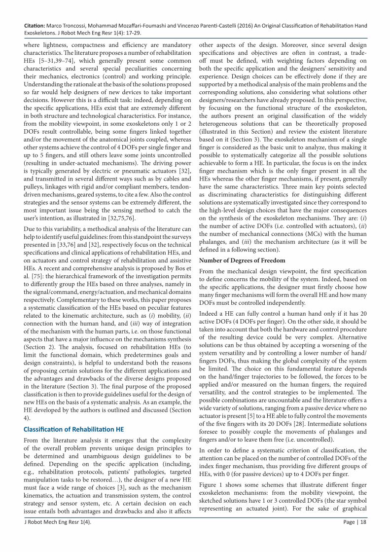
Figure 1 shows some schemes that illustrate different finger exoskeleton mechanisms: from the mobility viewpoint, the sketched solutions have 1 or 3 controlled DOFs (the star symbol representing an actuated joint). For the sake of graphical
J Robot Mech Eng Resr 1(4). Page | 19
Citation: Marco Troncossi, Mohammad Mozaffari-Foumashi and Vincenzo Parenti-Castelli (2016) An Original Classification of Rehabilitation Hand Exoskeletons. J Robot Mech Eng Resr 1(4): 17-29.
simplicity, the possibility of actuating the abduction/adduction movement is not reported among the schemes. It is worth noting that the mechanisms in Figure 1 (e, i, j) are under-actuated, i.e. the number of active DOFs is smaller than the kinematic DOFs of the mechanism (as counted for instance by the Grubler-Kutzbach formula).
Number of Mechanical Connection
The HEs are connected to the human finger phalanges to control the movement of fingers and to exchange forces/moments with them. For safety reasons, the imposed movements must be consistent with the physiological ones (i.e. the natural range of motion of the human articulations must be respected) and the loads transmitted to the human finger must be compatible with the human ability to painlessly bear forces. In this respect, a very important decision concerns the number of connections of the HE with each finger. Based on the number of MCs, three different groups can be identified, i.e. HEs with 1, 2 or 3 MCs per finger. In Figure 1 solutions with 1 or 3 MCs are reported as examples.
This classification principle is important for the synthesis of the mechanisms in the design phase, for control issues, and for practical aspects, e.g. the easiness of connecting the HE links to the human hand and fingers.
The exoskeleton can be attached to the finger by different means. This choice is another critical aspect, fundamental for the practical implementation of the HE in clinical practice. The most common and simple methods are attaching the mechanism to human finger by using flexible straps or rigid links wrapped around the phalanges, and/or thimbles fixed to the human fingertip. Another possible solution, increasingly widespread in recent years, is using a glove as an intermediate mean. In this case, the user wears the glove and the HE is connected to the glove [25,41,47,51,53,54]. It is worth noting that the stiffness of the connection can be a significant factor in different perspectives. A flexible strap can slightly move with respect to the phalanx, thus determining variable contact areas that can negatively affect the controllability and the accuracy of the system when following
Figure 1: Schematics of common mechanism architectures with one or three controlled DOFs and one or three MCs. The star symbols indicate actuated joints. (a) External/Integrated; (b) External/Stand-Alone; (c) External/Integrated; (d) External/Stand-Alone; (e) External/Integrated; (f) External/Integrated; (g, h) Lateral; (i, j) Internal
Citation: Marco Troncossi, Mohammad Mozaffari-Foumashi and Vincenzo Parenti-Castelli (2016) An Original Classification of Rehabilitation Hand Exoskeletons. J Robot Mech Eng Resr 1(4): 17-29.
J Robot Mech Eng Resr 1(4). Page | 20
certain trajectories. On the other hand, a flexible strap is easier to fix with respect to a stiffer solution, it is inherently safer (the compliance can work as a mechanical filter of forces) and, due to its intrinsic adaptability, it lets the HE accommodate slightly different size hands without the possible need to change the HE geometry. The final solution to be adopted strictly depends on patient pathologies (e.g. residual spastic forces following stroke represent a practical problem in the fitting phase, so that simple and flexible solutions are often preferred), on the need to adapt the HE to different hand sizes, on the direction and magnitude of forces to be transmitted to the human fingers. A definite guideline for the best option cannot thus be provided regardless of the specific application.
Mechanism Architecture
There could be many criteria to distinguish different mechanism architectures. In this paper, “architecture” refers to the arrangement of the exoskeleton power transmission system with respect to the human finger. In particular, two main high-level characteristics are considered as significant items to discriminate different technical solutions: (i) the positioning of the mechanism elements relative to the human finger hand (ii) the possible use of the anatomical parts as kinematic elements required to achieve the closure of the system, that would lead to two types of mechanism which are defined as Integrated Mechanism (where the human phalanges and articulations are included as essential links and joints of the transmission system, as for instance the case of Figure 1(a)) and Stand-Alone Mechanism (where the phalanges are attached to some moving links of a mechanism that works autonomously, as for instance in Figure 1(b)).
In Integrated Mechanisms the HE moves the fingers by means of kinematic chains which include the human fingers as integrating parts to achieve the kinematic closure. The concept can be easily explained referring to Figure 1(f), where the control of the distal phalanx motion is not of interest (i.e. it is kept free) whereas the movements of the proximal and middle phalanges are coupled, being part of a four-bar linkage made of the 2 phalanges, 2 artificial links, 2 revolute joints and 2 human articulations (considered as revolute joints as well). Many other linkages can be formed in a similar way (e.g. see Figure 1(a, c, e, f)).
For safety reasons a special care must be taken in order to respect the natural range of motion of the human articulations (e.g. hyperextension must be avoided). This means that in the mechanism synthesis the phalanx poses (position and orientation) should be checked all along the resulting trajectory.
The kinematic chain of the Stand-Alone Mechanisms is completely determined without the need of human finger parts. One or more phalanges are fixed to certain links of the mechanism without adding further DOFs or further constraints to the mechanism. A straightforward example is reported in Figure 1(b): the end-effector of a planar four-link serial manipulator with 3 DOFs controls the pose of the human fingertip that is attached to it. The introduction of the human finger in the kinematic chain of the mechanism (two additional links and three revolute joints) does not change the mobility of the system. From a mechanical point of view, things are more complex when there are more MCs so that intermediate links of the mechanism are connected to two or three phalanges and must make them rotate about their natural motion axis according to the desired trajectories.
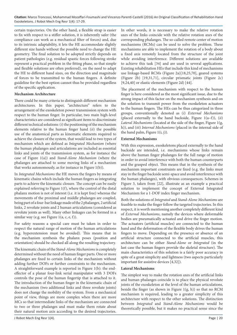
In other words, it is necessary to make the relative rotation axes of the links coincide with the relative rotation axes of the corresponding phalanges. The so-called remote center of motion mechanisms (RCMs) can be used to solve the problem. These mechanisms are able to implement the rotation of a body about a fixed axis remotely located from the structure of the joint while avoiding interference. Different solutions are available to achieve this task [34] and are used in several applications. Existing rehabilitation HEs that include this kind of mechanisms use linkage-based RCMs (Figure 2a)[18,25,70], geared systems (Figure 2b) [19,31,71], circular prismatic joints (Figure 2c) [9,24,40] or elastic elements (Figure 2d) [44].
The placement of the mechanism with respect to the human finger is here considered as the most significant issue, due to the strong impact of this factor on the mechanism synthesis and on the solution to transmit power from the exoskeleton actuators to the human fingers. The HEs can be thus categorized in three groups, conventionally denoted as (i) External Mechanisms (placed externally to the hand backside, Figure 1(a–f)), (ii) Lateral Mechanisms (located at the side of the finger, Figure 1(g, h)), and (iii) Internal Mechanisms (placed in the internal side of the hand palm, Figure 1(i, j)).
External Mechanisms
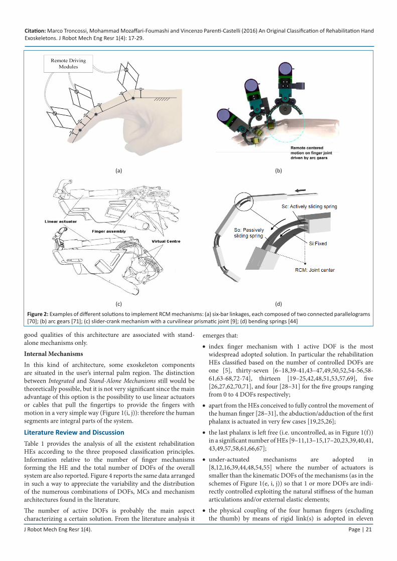
With this expression, exoskeletons placed externally to the hand backside are intended, i.e. mechanisms whose links remain above the human finger phalanges for the full range of motion in order to avoid interference with both the human counterparts and the grasped object. This means that in the synthesis of the mechanism important constraints are fixed (e.g. the links must stay in the finger backside semi-space and avoid interference with the human phalanges), with obvious consequences. Schemes in Figure 3, taken from [22], illustrate as an example a practical solution to implement the concept of External Integrated Mechanism for a 1-DOF index finger mechanism.
Both the solutions of Integrated and Stand-Alone Mechanisms are feasible to make the finger follow the targeted trajectories. In this respect, it is worth mentioning another completely different kind of External Mechanisms, namely the devices where deformable bodies are pneumatically actuated and drive the finger motion. The actuators (artificial muscles) are connected to the human hand and the deformation of the flexible body drives the human fingers to move. Depending on the presence or absence of an artificial structure connected to the artificial muscles, this architecture can be either Stand-Alone or Integrated (in the last case the human fingers provide the skeletal structure). The main characteristics of this solution is a fairly poor accuracy in spite of a great simplicity and lightness (two aspects particularly important for assistive devices [4,32]).
Lateral Mechanisms
The simplest way to make the rotation axes of the artificial links and human phalanges coincide is to place the physical revolute joints of the exoskeleton at the level of the human articulations, beside the finger (as shown in Figure 1(g, h)) so that no RCM mechanism is required, leading to a greater simplicity of this architecture with respect to the other solutions. The distinction between Integrated and Stand-Alone Mechanisms would be theoretically possible, but it makes no practical sense since the
J Robot Mech Eng Resr 1(4). Page | 21
Citation: Marco Troncossi, Mohammad Mozaffari-Foumashi and Vincenzo Parenti-Castelli (2016) An Original Classification of Rehabilitation Hand Exoskeletons. J Robot Mech Eng Resr 1(4): 17-29.
good qualities of this architecture are associated with stand-alone mechanisms only.
Internal Mechanisms
In this kind of architecture, some exoskeleton components are situated in the user’s internal palm region. The distinction between Integrated and Stand-Alone Mechanisms still would be theoretically possible, but it is not very significant since the main advantage of this option is the possibility to use linear actuators or cables that pull the fingertips to provide the fingers with motion in a very simple way (Figure 1(i, j)): therefore the human segments are integral parts of the system.
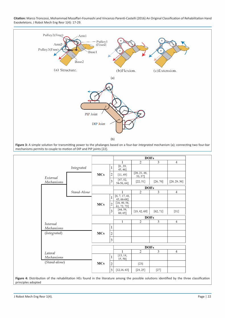
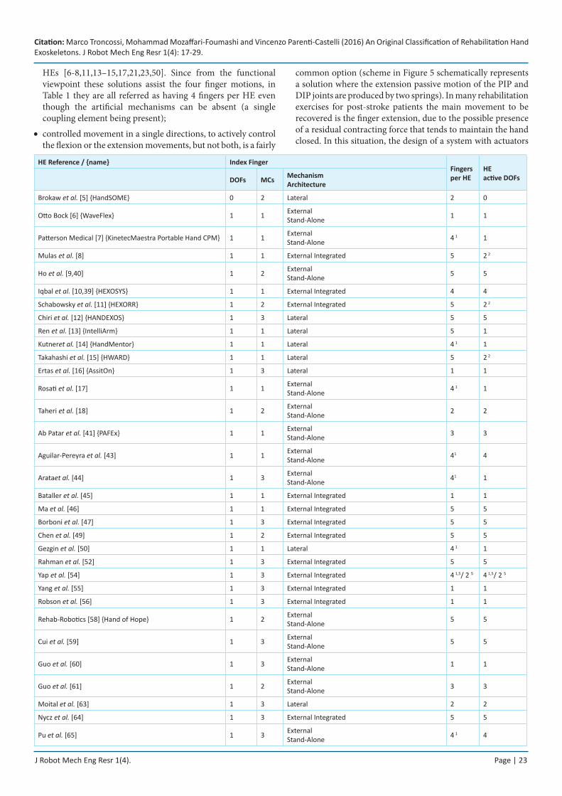
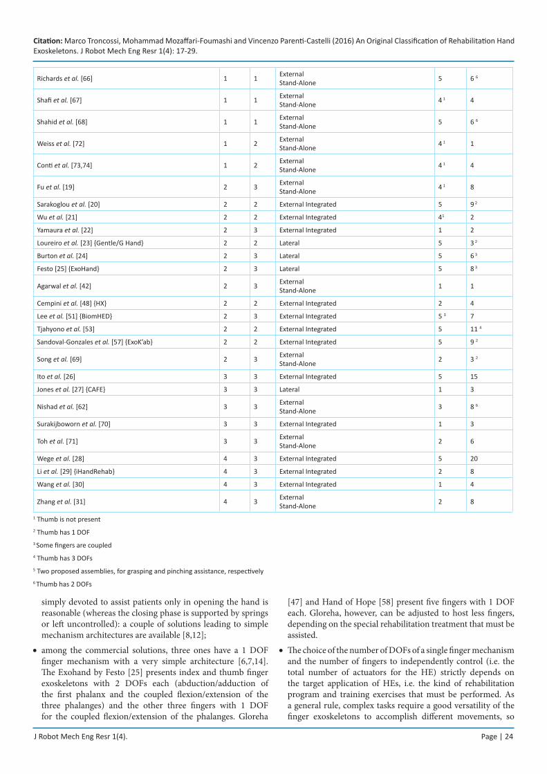
Literature Review and DiscussionTable 1 provides the analysis of all the existent rehabilitation HEs according to the three proposed classification principles. Information relative to the number of finger mechanisms forming the HE and the total number of DOFs of the overall system are also reported. Figure 4 reports the same data arranged in such a way to appreciate the variability and the distribution of the numerous combinations of DOFs, MCs and mechanism architectures found in the literature.
The number of active DOFs is probably the main aspect characterizing a certain solution. From the literature analysis it
emerges that:
index finger mechanism with 1 active DOF is the most •widespread adopted solution. In particular the rehabilitation HEs classified based on the number of controlled DOFs are one [5], thirty-seven [6–18,39-41,43–47,49,50,52,54-56,58-61,63-68,72-74], thirteen [19–25,42,48,51,53,57,69], five [26,27,62,70,71], and four [28–31] for the five groups ranging from 0 to 4 DOFs respectively;
apart from the HEs conceived to fully control the movement of •the human finger [28–31], the abduction/adduction of the first phalanx is actuated in very few cases [19,25,26];
the last phalanx is left free (i.e. uncontrolled, as in Figure 1(f)) •in a significant number of HEs [9–11,13–15,17–20,23,39,40,41, 43,49,57,58,61,66,67];
under-actuated mechanisms are adopted in •[8,12,16,39,44,48,54,55] where the number of actuators is smaller than the kinematic DOFs of the mechanisms (as in the schemes of Figure 1(e, i, j)) so that 1 or more DOFs are indi-rectly controlled exploiting the natural stiffness of the human articulations and/or external elastic elements;
the physical coupling of the four human fingers (excluding •the thumb) by means of rigid link(s) is adopted in eleven
(a) (b)
(c) (d)
Figure 2: Examples of different solutions to implement RCM mechanisms: (a) six-bar linkages, each composed of two connected parallelograms [70]; (b) arc gears [71]; (c) slider-crank mechanism with a curvilinear prismatic joint [9]; (d) bending springs [44]
Citation: Marco Troncossi, Mohammad Mozaffari-Foumashi and Vincenzo Parenti-Castelli (2016) An Original Classification of Rehabilitation Hand Exoskeletons. J Robot Mech Eng Resr 1(4): 17-29.
J Robot Mech Eng Resr 1(4). Page | 22
(a)
(b)
Figure 3: A simple solution for transmitting power to the phalanges based on a four-bar Integrated mechanism (a); connecting two four-bar mechanisms permits to couple to motion of DIP and PIP joints [22].
Figure 4: Distribution of the rehabilitation HEs found in the literature among the possible solutions identified by the three classification principles adopted
Citation: Marco Troncossi, Mohammad Mozaffari-Foumashi and Vincenzo Parenti-Castelli (2016) An Original Classification of Rehabilitation Hand Exoskeletons. J Robot Mech Eng Resr 1(4): 17-29.
J Robot Mech Eng Resr 1(4). Page | 23
HEs [6-8,11,13–15,17,21,23,50]. Since from the functional viewpoint these solutions assist the four finger motions, in Table 1 they are all referred as having 4 fingers per HE even though the artificial mechanisms can be absent (a single coupling element being present);
controlled movement in a single directions, to actively control •the flexion or the extension movements, but not both, is a fairly
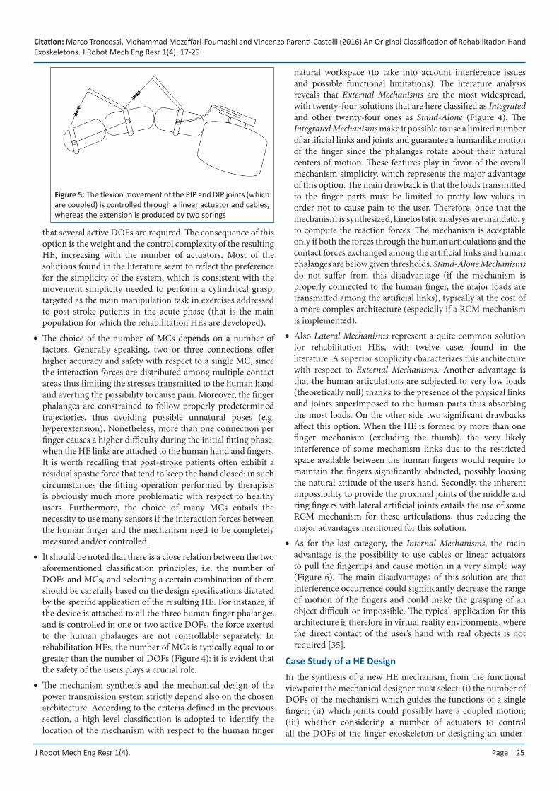
common option (scheme in Figure 5 schematically represents a solution where the extension passive motion of the PIP and DIP joints are produced by two springs). In many rehabilitation exercises for post-stroke patients the main movement to be recovered is the finger extension, due to the possible presence of a residual contracting force that tends to maintain the hand closed. In this situation, the design of a system with actuators
HE Reference / {name} Index FingerFingers per HE
HE active DOFsDOFs MCs Mechanism
Architecture
Brokaw et al. [5] {HandSOME} 0 2 Lateral 2 0
Otto Bock [6] {WaveFlex} 1 1 External Stand-Alone 1 1
Patterson Medical [7] {KinetecMaestra Portable Hand CPM} 1 1 External Stand-Alone 4 1 1
Mulas et al. [8] 1 1 External Integrated 5 2 2
Ho et al. [9,40] 1 2 External Stand-Alone 5 5
Iqbal et al. [10,39] {HEXOSYS} 1 1 External Integrated 4 4
Schabowsky et al. [11] {HEXORR} 1 2 External Integrated 5 2 2
Chiri et al. [12] {HANDEXOS} 1 3 Lateral 5 5
Ren et al. [13] {IntelliArm} 1 1 Lateral 5 1
Kutneret al. [14] {HandMentor} 1 1 Lateral 4 1 1
Takahashi et al. [15] {HWARD} 1 1 Lateral 5 2 2
Ertas et al. [16] {AssitOn} 1 3 Lateral 1 1
Rosati et al. [17] 1 1 External Stand-Alone 4 1 1
Taheri et al. [18] 1 2 External Stand-Alone 2 2
Ab Patar et al. [41] {PAFEx} 1 1 External Stand-Alone 3 3
Aguilar-Pereyra et al. [43] 1 1 External Stand-Alone 41 4
Arataet al. [44] 1 3 External Stand-Alone 41 1
Bataller et al. [45] 1 1 External Integrated 1 1
Ma et al. [46] 1 1 External Integrated 5 5
Borboni et al. [47] 1 3 External Integrated 5 5
Chen et al. [49] 1 2 External Integrated 5 5
Gezgin et al. [50] 1 1 Lateral 4 1 1
Rahman et al. [52] 1 3 External Integrated 5 5
Yap et al. [54] 1 3 External Integrated 4 1,5/ 2 5 4 1,5/ 2 5
Yang et al. [55] 1 3 External Integrated 1 1
Robson et al. [56] 1 3 External Integrated 1 1
Rehab-Robotics [58] {Hand of Hope} 1 2 External Stand-Alone 5 5
Cui et al. [59] 1 3 External Stand-Alone 5 5
Guo et al. [60] 1 3 External Stand-Alone 1 1
Guo et al. [61] 1 2 External Stand-Alone 3 3
Moital et al. [63] 1 3 Lateral 2 2
Nycz et al. [64] 1 3 External Integrated 5 5
Pu et al. [65] 1 3 External Stand-Alone 4 1 4
Citation: Marco Troncossi, Mohammad Mozaffari-Foumashi and Vincenzo Parenti-Castelli (2016) An Original Classification of Rehabilitation Hand Exoskeletons. J Robot Mech Eng Resr 1(4): 17-29.
J Robot Mech Eng Resr 1(4). Page | 24
Richards et al. [66] 1 1 External Stand-Alone 5 6 6
Shafi et al. [67] 1 1 External Stand-Alone 4 1 4
Shahid et al. [68] 1 1 External Stand-Alone 5 6 6
Weiss et al. [72] 1 2 External Stand-Alone 4 1 1
Conti et al. [73,74] 1 2 External Stand-Alone 4 1 4
Fu et al. [19] 2 3 External Stand-Alone 4 1 8
Sarakoglou et al. [20] 2 2 External Integrated 5 9 2
Wu et al. [21] 2 2 External Integrated 41 2
Yamaura et al. [22] 2 3 External Integrated 1 2
Loureiro et al. [23] {Gentle/G Hand} 2 2 Lateral 5 3 2
Burton et al. [24] 2 3 Lateral 5 6 3
Festo [25] {ExoHand} 2 3 Lateral 5 8 3
Agarwal et al. [42] 2 3 External Stand-Alone 1 1
Cempini et al. [48] {HX} 2 2 External Integrated 2 4
Lee et al. [51] {BiomHED} 2 3 External Integrated 5 3 7
Tjahyono et al. [53] 2 2 External Integrated 5 11 4
Sandoval-Gonzales et al. [57] {ExoK’ab} 2 2 External Integrated 5 9 2
Song et al. [69] 2 3 External Stand-Alone 2 3 2
Ito et al. [26] 3 3 External Integrated 5 15
Jones et al. [27] {CAFE} 3 3 Lateral 1 3
Nishad et al. [62] 3 3 External Stand-Alone 3 8 6
Surakijboworn et al. [70] 3 3 External Integrated 1 3
Toh et al. [71] 3 3 External Stand-Alone 2 6
Wege et al. [28] 4 3 External Integrated 5 20
Li et al. [29] {iHandRehab} 4 3 External Integrated 2 8
Wang et al. [30] 4 3 External Integrated 1 4
Zhang et al. [31] 4 3 External Stand-Alone 2 8
1 Thumb is not present2 Thumb has 1 DOF 3 Some fingers are coupled4 Thumb has 3 DOFs 5 Two proposed assemblies, for grasping and pinching assistance, respectively6 Thumb has 2 DOFs
simply devoted to assist patients only in opening the hand is reasonable (whereas the closing phase is supported by springs or left uncontrolled): a couple of solutions leading to simple mechanism architectures are available [8,12];
among the commercial solutions, three ones have a 1 DOF •finger mechanism with a very simple architecture [6,7,14]. The Exohand by Festo [25] presents index and thumb finger exoskeletons with 2 DOFs each (abduction/adduction of the first phalanx and the coupled flexion/extension of the three phalanges) and the other three fingers with 1 DOF for the coupled flexion/extension of the phalanges. Gloreha
[47] and Hand of Hope [58] present five fingers with 1 DOF each. Gloreha, however, can be adjusted to host less fingers, depending on the special rehabilitation treatment that must be assisted.
The choice of the number of DOFs of a single finger mechanism •and the number of fingers to independently control (i.e. the total number of actuators for the HE) strictly depends on the target application of HEs, i.e. the kind of rehabilitation program and training exercises that must be performed. As a general rule, complex tasks require a good versatility of the finger exoskeletons to accomplish different movements, so
Citation: Marco Troncossi, Mohammad Mozaffari-Foumashi and Vincenzo Parenti-Castelli (2016) An Original Classification of Rehabilitation Hand Exoskeletons. J Robot Mech Eng Resr 1(4): 17-29.
J Robot Mech Eng Resr 1(4). Page | 25
Figure 5: The flexion movement of the PIP and DIP joints (which are coupled) is controlled through a linear actuator and cables, whereas the extension is produced by two springs
that several active DOFs are required. The consequence of this option is the weight and the control complexity of the resulting HE, increasing with the number of actuators. Most of the solutions found in the literature seem to reflect the preference for the simplicity of the system, which is consistent with the movement simplicity needed to perform a cylindrical grasp, targeted as the main manipulation task in exercises addressed to post-stroke patients in the acute phase (that is the main population for which the rehabilitation HEs are developed).
The choice of the number of MCs depends on a number of •factors. Generally speaking, two or three connections offer higher accuracy and safety with respect to a single MC, since the interaction forces are distributed among multiple contact areas thus limiting the stresses transmitted to the human hand and averting the possibility to cause pain. Moreover, the finger phalanges are constrained to follow properly predetermined trajectories, thus avoiding possible unnatural poses (e.g. hyperextension). Nonetheless, more than one connection per finger causes a higher difficulty during the initial fitting phase, when the HE links are attached to the human hand and fingers. It is worth recalling that post-stroke patients often exhibit a residual spastic force that tend to keep the hand closed: in such circumstances the fitting operation performed by therapists is obviously much more problematic with respect to healthy users. Furthermore, the choice of many MCs entails the necessity to use many sensors if the interaction forces between the human finger and the mechanism need to be completely measured and/or controlled.
It should be noted that there is a close relation between the two •aforementioned classification principles, i.e. the number of DOFs and MCs, and selecting a certain combination of them should be carefully based on the design specifications dictated by the specific application of the resulting HE. For instance, if the device is attached to all the three human finger phalanges and is controlled in one or two active DOFs, the force exerted to the human phalanges are not controllable separately. In rehabilitation HEs, the number of MCs is typically equal to or greater than the number of DOFs (Figure 4): it is evident that the safety of the users plays a crucial role.
The mechanism synthesis and the mechanical design of the •power transmission system strictly depend also on the chosen architecture. According to the criteria defined in the previous section, a high-level classification is adopted to identify the location of the mechanism with respect to the human finger
natural workspace (to take into account interference issues and possible functional limitations). The literature analysis reveals that External Mechanisms are the most widespread, with twenty-four solutions that are here classified as Integrated and other twenty-four ones as Stand-Alone (Figure 4). The Integrated Mechanisms make it possible to use a limited number of artificial links and joints and guarantee a humanlike motion of the finger since the phalanges rotate about their natural centers of motion. These features play in favor of the overall mechanism simplicity, which represents the major advantage of this option. The main drawback is that the loads transmitted to the finger parts must be limited to pretty low values in order not to cause pain to the user. Therefore, once that the mechanism is synthesized, kinetostatic analyses are mandatory to compute the reaction forces. The mechanism is acceptable only if both the forces through the human articulations and the contact forces exchanged among the artificial links and human phalanges are below given thresholds. Stand-Alone Mechanisms do not suffer from this disadvantage (if the mechanism is properly connected to the human finger, the major loads are transmitted among the artificial links), typically at the cost of a more complex architecture (especially if a RCM mechanism is implemented).
Also • Lateral Mechanisms represent a quite common solution for rehabilitation HEs, with twelve cases found in the literature. A superior simplicity characterizes this architecture with respect to External Mechanisms. Another advantage is that the human articulations are subjected to very low loads (theoretically null) thanks to the presence of the physical links and joints superimposed to the human parts thus absorbing the most loads. On the other side two significant drawbacks affect this option. When the HE is formed by more than one finger mechanism (excluding the thumb), the very likely interference of some mechanism links due to the restricted space available between the human fingers would require to maintain the fingers significantly abducted, possibly loosing the natural attitude of the user’s hand. Secondly, the inherent impossibility to provide the proximal joints of the middle and ring fingers with lateral artificial joints entails the use of some RCM mechanism for these articulations, thus reducing the major advantages mentioned for this solution.
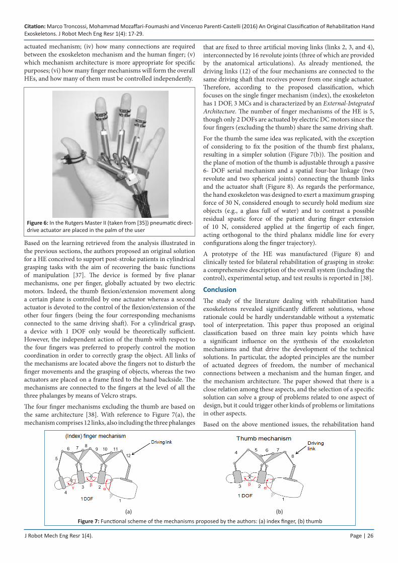
As for the last category, the • Internal Mechanisms, the main advantage is the possibility to use cables or linear actuators to pull the fingertips and cause motion in a very simple way (Figure 6). The main disadvantages of this solution are that interference occurrence could significantly decrease the range of motion of the fingers and could make the grasping of an object difficult or impossible. The typical application for this architecture is therefore in virtual reality environments, where the direct contact of the user’s hand with real objects is not required [35].
Case Study of a HE DesignIn the synthesis of a new HE mechanism, from the functional viewpoint the mechanical designer must select: (i) the number of DOFs of the mechanism which guides the functions of a single finger; (ii) which joints could possibly have a coupled motion; (iii) whether considering a number of actuators to control all the DOFs of the finger exoskeleton or designing an under-
Citation: Marco Troncossi, Mohammad Mozaffari-Foumashi and Vincenzo Parenti-Castelli (2016) An Original Classification of Rehabilitation Hand Exoskeletons. J Robot Mech Eng Resr 1(4): 17-29.
J Robot Mech Eng Resr 1(4). Page | 26
actuated mechanism; (iv) how many connections are required between the exoskeleton mechanism and the human finger; (v) which mechanism architecture is more appropriate for specific purposes; (vi) how many finger mechanisms will form the overall HEs, and how many of them must be controlled independently.
Based on the learning retrieved from the analysis illustrated in the previous sections, the authors proposed an original solution for a HE conceived to support post-stroke patients in cylindrical grasping tasks with the aim of recovering the basic functions of manipulation [37]. The device is formed by five planar mechanisms, one per finger, globally actuated by two electric motors. Indeed, the thumb flexion/extension movement along a certain plane is controlled by one actuator whereas a second actuator is devoted to the control of the flexion/extension of the other four fingers (being the four corresponding mechanisms connected to the same driving shaft). For a cylindrical grasp, a device with 1 DOF only would be theoretically sufficient. However, the independent action of the thumb with respect to the four fingers was preferred to properly control the motion coordination in order to correctly grasp the object. All links of the mechanisms are located above the fingers not to disturb the finger movements and the grasping of objects, whereas the two actuators are placed on a frame fixed to the hand backside. The mechanisms are connected to the fingers at the level of all the three phalanges by means of Velcro straps.
The four finger mechanisms excluding the thumb are based on the same architecture [38]. With reference to Figure 7(a), the mechanism comprises 12 links, also including the three phalanges
Figure 6: In the Rutgers Master II (taken from [35]) pneumatic direct-drive actuator are placed in the palm of the user
(a) (b)
Figure 7: Functional scheme of the mechanisms proposed by the authors: (a) index finger, (b) thumb
that are fixed to three artificial moving links (links 2, 3, and 4), interconnected by 16 revolute joints (three of which are provided by the anatomical articulations). As already mentioned, the driving links (12) of the four mechanisms are connected to the same driving shaft that receives power from one single actuator. Therefore, according to the proposed classification, which focuses on the single finger mechanism (index), the exoskeleton has 1 DOF, 3 MCs and is characterized by an External-Integrated Architecture. The number of finger mechanisms of the HE is 5, though only 2 DOFs are actuated by electric DC motors since the four fingers (excluding the thumb) share the same driving shaft.
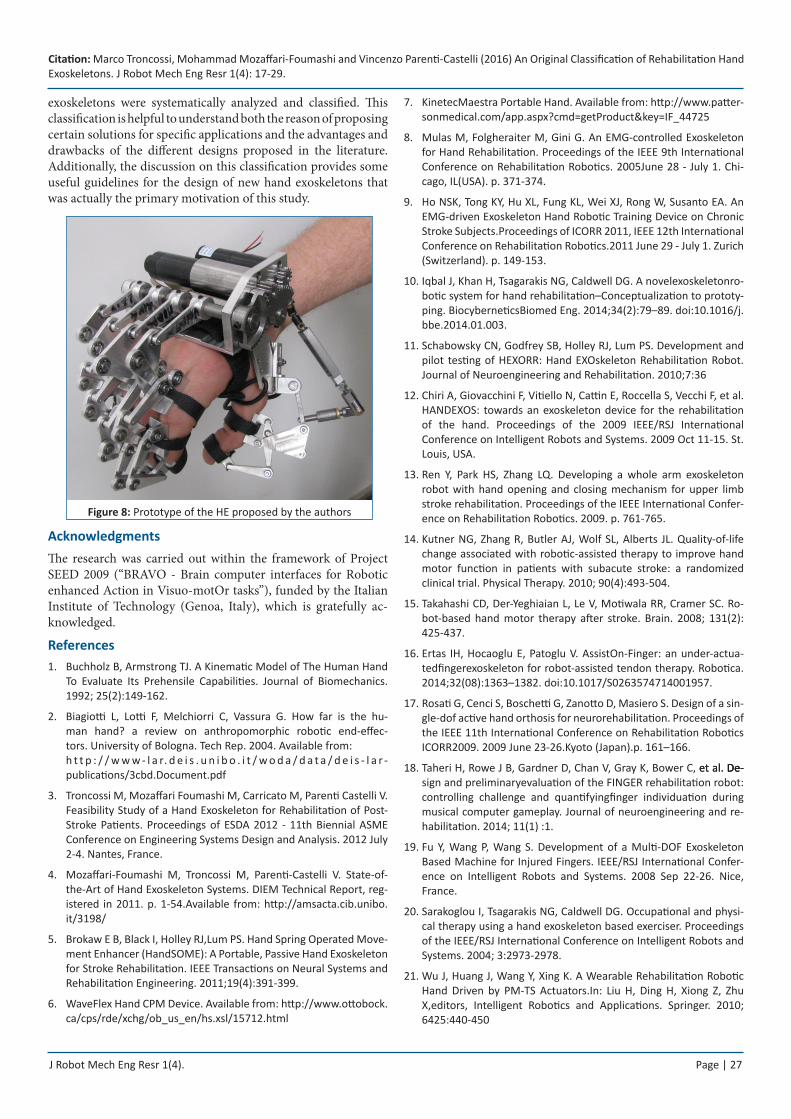
For the thumb the same idea was replicated, with the exception of considering to fix the position of the thumb first phalanx, resulting in a simpler solution (Figure 7(b)). The position and the plane of motion of the thumb is adjustable through a passive 6- DOF serial mechanism and a spatial four-bar linkage (two revolute and two spherical joints) connecting the thumb links and the actuator shaft (Figure 8). As regards the performance, the hand exoskeleton was designed to exert a maximum grasping force of 30 N, considered enough to securely hold medium size objects (e.g., a glass full of water) and to contrast a possible residual spastic force of the patient during finger extension of 10 N, considered applied at the fingertip of each finger, acting orthogonal to the third phalanx middle line for every configurations along the finger trajectory).
A prototype of the HE was manufactured (Figure 8) and clinically tested for bilateral rehabilitation of grasping in stroke: a comprehensive description of the overall system (including the control), experimental setup, and test results is reported in [38].
ConclusionThe study of the literature dealing with rehabilitation hand exoskeletons revealed significantly different solutions, whose rationale could be hardly understandable without a systematic tool of interpretation. This paper thus proposed an original classification based on three main key points which have a significant influence on the synthesis of the exoskeleton mechanisms and that drive the development of the technical solutions. In particular, the adopted principles are the number of actuated degrees of freedom, the number of mechanical connections between a mechanism and the human finger, and the mechanism architecture. The paper showed that there is a close relation among these aspects, and the selection of a specific solution can solve a group of problems related to one aspect of design, but it could trigger other kinds of problems or limitations in other aspects.
Based on the above mentioned issues, the rehabilitation hand
Citation: Marco Troncossi, Mohammad Mozaffari-Foumashi and Vincenzo Parenti-Castelli (2016) An Original Classification of Rehabilitation Hand Exoskeletons. J Robot Mech Eng Resr 1(4): 17-29.
J Robot Mech Eng Resr 1(4). Page | 27
exoskeletons were systematically analyzed and classified. This classification is helpful to understand both the reason of proposing certain solutions for specific applications and the advantages and drawbacks of the different designs proposed in the literature. Additionally, the discussion on this classification provides some useful guidelines for the design of new hand exoskeletons that was actually the primary motivation of this study.
Figure 8: Prototype of the HE proposed by the authors
AcknowledgmentsThe research was carried out within the framework of Project SEED 2009 (“BRAVO - Brain computer interfaces for Robotic enhanced Action in Visuo-motOr tasks”), funded by the Italian Institute of Technology (Genoa, Italy), which is gratefully ac-knowledged.
ReferencesBuchholz B, Armstrong TJ. A Kinematic Model of The Human Hand 1. To Evaluate Its Prehensile Capabilities. Journal of Biomechanics. 1992; 25(2):149-162.
Biagiotti L, Lotti F, Melchiorri C, Vassura G. How far is the hu-2. man hand? a review on anthropomorphic robotic end-effec-tors. University of Bologna. Tech Rep. 2004. Available from: h t t p : / / w w w - l a r. d e i s . u n i b o . i t / w o d a / d a t a / d e i s - l a r -publications/3cbd.Document.pdf
Troncossi M, Mozaffari Foumashi M, Carricato M, Parenti Castelli V. 3. Feasibility Study of a Hand Exoskeleton for Rehabilitation of Post-Stroke Patients. Proceedings of ESDA 2012 - 11th Biennial ASME Conference on Engineering Systems Design and Analysis. 2012 July 2-4. Nantes, France.
Mozaffari-Foumashi M, Troncossi M, Parenti-Castelli V. State-of-4. the-Art of Hand Exoskeleton Systems. DIEM Technical Report, reg-istered in 2011. p. 1-54.Available from: http://amsacta.cib.unibo.it/3198/
Brokaw E B, Black I, Holley RJ,Lum PS. Hand Spring Operated Move-5. ment Enhancer (HandSOME): A Portable, Passive Hand Exoskeleton for Stroke Rehabilitation. IEEE Transactions on Neural Systems and Rehabilitation Engineering. 2011;19(4):391-399.
WaveFlex Hand CPM Device. Available from: 6. http://www.ottobock.ca/cps/rde/xchg/ob_us_en/hs.xsl/15712.html
KinetecMaestra Portable Hand. Available from: 7. http://www.patter-sonmedical.com/app.aspx?cmd=getProduct&key=IF_44725
Mulas M, Folgheraiter M, Gini G. An EMG-controlled Exoskeleton 8. for Hand Rehabilitation. Proceedings of the IEEE 9th International Conference on Rehabilitation Robotics. 2005June 28 - July 1. Chi-cago, IL(USA). p. 371-374.
Ho NSK, Tong KY, Hu XL, Fung KL, Wei XJ, Rong W, Susanto EA. An 9. EMG-driven Exoskeleton Hand Robotic Training Device on Chronic Stroke Subjects.Proceedings of ICORR 2011, IEEE 12th International Conference on Rehabilitation Robotics.2011 June 29 - July 1. Zurich (Switzerland). p. 149-153.
Iqbal J, Khan H, Tsagarakis NG, Caldwell DG. A novelexoskeletonro-10. botic system for hand rehabilitation–Conceptualization to prototy-ping. BiocyberneticsBiomed Eng. 2014;34(2):79–89. doi:10.1016/j.bbe.2014.01.003.
Schabowsky CN, Godfrey SB, Holley RJ, Lum PS. Development and 11. pilot testing of HEXORR: Hand EXOskeleton Rehabilitation Robot. Journal of Neuroengineering and Rehabilitation. 2010;7:36
Chiri A, Giovacchini F, Vitiello N, Cattin E, Roccella S, Vecchi F, et al. 12. HANDEXOS: towards an exoskeleton device for the rehabilitation of the hand. Proceedings of the 2009 IEEE/RSJ International Conference on Intelligent Robots and Systems. 2009 Oct 11-15. St. Louis, USA.
Ren Y, Park HS, Zhang LQ. Developing a whole arm exoskeleton 13. robot with hand opening and closing mechanism for upper limb stroke rehabilitation. Proceedings of the IEEE International Confer-ence on Rehabilitation Robotics. 2009. p. 761-765.
Kutner NG, Zhang R, Butler AJ, Wolf SL, Alberts JL. Quality-of-life 14. change associated with robotic-assisted therapy to improve hand motor function in patients with subacute stroke: a randomized clinical trial. Physical Therapy. 2010; 90(4):493-504.
Takahashi CD, Der-Yeghiaian L, Le V, Motiwala RR, Cramer SC. Ro-15. bot-based hand motor therapy after stroke. Brain. 2008; 131(2): 425-437.
Ertas IH, Hocaoglu E, Patoglu V. AssistOn-Finger: an under-actua-16. tedfingerexoskeleton for robot-assisted tendon therapy. Robotica. 2014;32(08):1363–1382. doi:10.1017/S0263574714001957.
Rosati G, Cenci S, Boschetti G, Zanotto D, Masiero S. Design of a sin-17. gle-dof active hand orthosis for neurorehabilitation. Proceedings of the IEEE 11th International Conference on Rehabilitation Robotics ICORR2009. 2009 June 23-26.Kyoto (Japan).p. 161–166.
Taheri H, Rowe J B, Gardner D, Chan V, Gray K, Bower C, et al. De-et al. De- De-18. sign and preliminaryevaluation of the FINGER rehabilitation robot: controlling challenge and quantifyingfinger individuation during musical computer gameplay. Journal of neuroengineering and re-habilitation. 2014; 11(1) :1.
Fu Y, Wang P, Wang S. Development of a Multi-DOF Exoskeleton 19. Based Machine for Injured Fingers. IEEE/RSJ International Confer-ence on Intelligent Robots and Systems. 2008 Sep 22-26. Nice, France.
Sarakoglou I, Tsagarakis NG, Caldwell DG. Occupational and physi-20. cal therapy using a hand exoskeleton based exerciser. Proceedings of the IEEE/RSJ International Conference on Intelligent Robots and Systems. 2004; 3:2973-2978.
Wu J, Huang J, Wang Y, Xing K. A Wearable Rehabilitation Robotic 21. Hand Driven by PM-TS Actuators.In: Liu H, Ding H, Xiong Z, Zhu X,editors, Intelligent Robotics and Applications. Springer. 2010; 6425:440-450
Citation: Marco Troncossi, Mohammad Mozaffari-Foumashi and Vincenzo Parenti-Castelli (2016) An Original Classification of Rehabilitation Hand Exoskeletons. J Robot Mech Eng Resr 1(4): 17-29.
J Robot Mech Eng Resr 1(4). Page | 28
Yamaura H, Matsushita K, Kato R, Yokoi H. Development of Hand 22. Rehabilitation System for Paralysis Patient – Universal Design Using Wire-Driven Mechanism. 31st Annual International Conference of the IEEE EMBS. 2009 Sep 2-6. Minneapolis, Minnesota (USA).
Loureiro RCV,Harwin WS. Reach & Grasp Therapy: Design and Con-23. trol of a 9-DOF Robotic Neuro-rehabilitation System. Proceedings of the IEEE 10th International Conference on Rehabilitation Robot-ics. 2007 June 12-15.Noordwijk, The Netherlands. p. 757-763.
Burton TMW,Vaidyanathan R, Burgess SC, Turton AJ,Melhuish C. 24. Development of a Parametric Kinematic Model of the Human Hand and a Novel Robotic Exoskeleton.Proceedings of ICORR 2011, IEEE 12th International Conference on Rehabilitation Robotics. 2011 June 29 - July 1. Zurich (Switzerland). p. 172-178.
FestoExoHand. Available from:25. http://www.festo.com/cms/en_corp/12713.htm
Ito S, Kawasaki H, Ishigure Y, Natsume M, Mouri T, Nishimoto Y. 26. A design of fine motion assist equipment for disabled hand in ro-botic rehabilitation system.Journal of the Franklin Institute. 2009; 348(1):79–89.
Jones CL, Wang F, Morrison R, Sarkar N, Kamper DG. Design and 27. development of the cable actuated finger exoskeleton for hand rehabilitation following stroke. IEEE/ASME Trans Mechatron. 2014;19(1):131–40.doi:10.1109/TMECH.2012.2224359.
Wege A,Hommel G. Development and Control of a Hand Exoskel-28. eton for Rehabilitation of Hand Injuries. Proceedings of the 2007 IEEE International Conference on Robotics and Biomimetics. 2007 Dec 15 -18.Sanya (China).
Li J, Zheng R, Zhang Y, Yao J. iHand Rehab: an Interactive Hand 29. Exoskeleton for Active and Passive Rehabilitation. Proceedings of ICORR 2011, IEEE 12th International Conference on Rehabilitation Robotics. 2011 June 29 - July 1. Zurich (Switzerland). p. 422-427.
Wang J, Li J, Zhang Y, Wang S. Design of an Exoskeleton for Index 30. Finger Rehabilitation. Proceedings of the 31st Annual International Conference of the IEEE EMBS. 2009 Sep 2-6. Minneapolis, Minne-sota (USA).
Zhang F, Hua L, Fu Y, Chen H, Wang S. Design and develop-31. ment of a hand exoskeleton for rehabilitation of hand inju-ries. Mech Mach Theory. 2014; 73:103–16. doi:10.1016/j.mechmachtheory.2013.10.015.
Heo P, Min Gu G, Lee S, Rhee K, Kim J. Current Hand Exoskeleton 32. Technologies for Rehabilitation and Assistive Engineering. Interna-tional Journal of Precision Engineering and Manufacturing. 2012; 13(5):807-824.
Balasubramanian S, Klein J, Burdet E. Robot-assisted rehabilitation 33. of hand function. Current Opinion in Neurology. 2010; 23:661–670.
Zong G, Pei X, Yu J, Bi S. Classification and type synthesis of 1-DOF 34. remote center of motion mechanisms. Mechanism and Machine Theory. 2008; 43(12):1585–1595.
Bouzit M, Burdea G, Popescu G,Boian R. The Rutgers Master II—35. New Design Force-Feedback Glove.IEEE/ASME Transactions On Mechatronics. 2002;7(2):256-263
In H, Kang BB, Sin M, Cho K-j. Exo-Glove: A Wearable Robot for the 36. Hand with a Soft Tendon Routing System. IEEE Rob Autom Mag. 2015;22(1):97–105. doi:10.1109/MRA.2014.2362863.
Bergamasco M, Frisoli A, Fontana M, Loconsole C, Leonardis D, 37. Troncossi M, et al. Preliminary Results of BRAVO Project - Brain Computer Interface for Robotic Enhanced Rehabilitation.Proceed-ings of ICORR 2011, IEEE 12th International Conference on Reha-bilitation Robotics. 2011 June 29 – July 1. Zurich (Switzerland). p. 364–370.
Leonardis D, Barsotti M, Loconsole C, Solazzi M, Troncossi M, Maz-38. zotti C, et al. An EMG-Controlled Robotic Hand Exoskeleton for Bi-lateral Rehabilitation. IEEE Transaction on Haptics. 2015; 8(2):140-151. doi: 10.1109/TOH.2015.2417570.
Iqbal J, Caldwell DG, Tsagarakis NG. Four-fingered lightweight exo-39. skeleton robotic device accommodating different hand sizes. Elec-tron Letters. 2015;51(12):888–90. doi:10.1049/el.2015.0850.
Susanto E, Tong RKY, Ockenfeld C, Ho NSK. Efficacy of robot-assisted 40. fingers training in chronic stroke survivors: a pilot randomized-con-trolled trial. Journal of NeuroEngineering and Rehabilitation. 2015; 12:42.
Patar Ab, Komeda MNA, Low T, Mahmud CY. J. System Integration 41. and Control of FingerOrthosis for Post Stroke Rehabilitation.Proce-diaTechnology. 2014 ;15 :755-764.
Agarwal P, Fox J, Yun Y, O’Malley MK, Deshpande AD. An index 42. finger exoskeleton with series elastic actuation for rehabilitation: Design, control and performance characterization. Int J Robot Res. 2015;34(14):1747–1772. doi:10.1177/0278364915598388.
Aguilar-Pereyra JP, Castillo-Castaneda E. Design of a Reconfigu-43. rable Robotic System for Flexoextension Fitted to Hand Fingers Size, Applied Bionics and Biomechanics. 2016:10. doi:http://dx.doi.org/10.1155/2016/1712831.
Arata J, Ohmoto K, Gassert R, Lambercy O, Fujimoto H, Wada I. 44. A new hand exoskeleton device for rehabilitation using a three-layered sliding spring mechanism. In: 2013 IEEE International Con-ference on Robotics and Automation (ICRA). Karlsruhe; 2013. p. 3902–907. doi:10.1109/ICRA.2013.6631126.
Bataller A, Cabrera JA, Clavijo M, Castillo JJ, Evolutionary synthesis 45. of mechanisms applied to the design of an exoskeleton for finger rehabilitation, Mechanism and Machine Theory. 2016; 105:31–43
Ma Z, Ben-Tzvi P. Design and Optimization of a Five-Finger Haptic 46. Glove Mechanism. ASME J. Mech. Rob. 2015;7(4):041008.
Borboni A, Mor M, Faglia R. Gloreha—Hand Robotic Rehabilitation: 47. Design, Mechanical Model, and Experiments.J. Dyn. Sys. Meas. Control . 2016; 138(11):1-12.doi: 10.1115/1.4033831.
Cempini M, Cortese M, Vitiello N. A Powered Finger-Thumb 48. Wearable Hand Exoskeleton With Self-Aligning Joint Axes. IEEE/ASME Trans Mechatron. 2015;20(2):705–16. doi:10.1109/TMECH.2014.2315528.
Chen Z, Fan S, Zhang D. An Exoskeleton System for Hand Rehabili-49. tation Based on Master-Slave Control. In: Intelligent Robotics and Applications; 2014:242–53. doi:10.1007/978-3-319-13966-1_25.
Gezgin E, Chang PH, Akhan AF. Synthesis of a Watt II six-bar linkage 50. in the design of a hand rehabilitation robot. Mechanism and Ma-chine Theory.2016;104:177-189.
Lee SW, Landers KA, Park HS. Development of a biomimetic 51. hand exotendon device (BiomHED) for restoration of functional hand movement post-stroke. IEEE Trans Neural SystRehabil Eng. 2014;22(4): 886–98. doi:10.1109/TNSRE.2014.2298362.
Citation: Marco Troncossi, Mohammad Mozaffari-Foumashi and Vincenzo Parenti-Castelli (2016) An Original Classification of Rehabilitation Hand Exoskeletons. J Robot Mech Eng Resr 1(4): 17-29.
J Robot Mech Eng Resr 1(4). Page | 29
Rahman A, Al-Jumaily A. Design and development of a bilateral ther-52. apeutic hand device for stroke rehabilitation. International Journal of Advanced Robotic Systems. 2013;10:405. doi:10.5772/56809.
Tjahyono AP, Aw KC, Devaraj H, Surendra WA, Haemmerle E, Tra-53. vas-Sejdic J. A five-fingered hand exoskeleton driven by pneumatic artificial muscles with novel polypyrrole sensors. Ind Robot Int J. 2013;40(3):251–60. doi:10.1108/01439911311309951.
Yap HK, Lim JH, Nasrallah F, Goh JCH, Yeow RCH. A soft exoskel-54. etonfor hand assistive and rehabilitation application using pneu-maticactuators with variable stiffness. In: 2015 IEEE International Conferenceon Robotics and Automation (ICRA). Seattle, WA; 2015. p. 4967–972. doi:10.1109/ICRA.2015.7139889.
Yang J, Xie H, Shi J. A novel motion-coupling design for a jointless 55. tendon-driven finger exoskeleton for rehabilitation. Mechanism and Machine Theory. 2016; 99:83-102.
Robson N, Soh GS. Geometric design of eight-bar wearable device 56. based on limb physiological contact task. Mechanism and Machine Theory. 2016; 100:358-367.
Sandoval-Gonzalez O, Jacinto-Villegas J, Herrera-Aguilar I, Portillo-57. Rodiguez O, Tripicchio P, Hernandez-Ramos M, et al. Design and Development of a Hand Exoskeleton Robot for Active and Passive Rehabilitation.International Journal of Advanced Robotic Systems. 2016; 13(66):1-12.doi: 10.5772/62404.
Available from:58. http://www.rehab-robotics.com/intro.html
Cui L, Phan A, Allison G. Design and fabrication of a three dimen-59. sional printable non-assembly articulated hand exoskeleton for re-habilitation. In: 2015 37th Annual International Conference of the IEEE Engineering in Medicine and Biology Society (EMBC). Milan; 2015. p. 4627–630. doi:10.1109/EMBC.2015.7319425.
Guo S, Zhang F, Wei W, Zhao F, Wang Y. Kinematic analysis of a novel 60. exoskeleton finger rehabilitation robot for stroke patients. In: 2014 IEEE International Conference on Mechatronics and Automation (ICMA). Tianjin; 2014. p. 924–9. doi:10.1109/ICMA.2014.6885821.
Guo S, Zhang W, Guo J, Gao J, Hu Y. Design and kinematic simula-61. tion of a novelexoskeletonrehabilitation hand robot. IEEE Interna-tional Conference on Mechatronics and Automation (ICMA). 2016. p. 1125-1130.
Nishad SS, Dutta A, Saxena A. Design and control of a three fin-62. ger hand exoskeleton for translation of a slender object. In: 2014 11th International Conference on Ubiquitous Robots and Ambient Intelligence (URAI). Kuala Lumpur. 2014. p. 179–84. doi:10.1109/URAI.2014.7057526.
Moital AR, Dogramadzi S, Ferreira HA. Development of an EMG 63. controlled hand exoskeleton for post-stroke rehabilitation. In: Pro-ceedings of the 3rd 2015 Workshop on ICTs for improving Patients RehabilitationResearch Techniques.2015. p. 66-72.
Nycz CJ, Delph MA, Fischer GS. Modeling and design of a tendon 64. actuated soft robotic exoskeleton for hemiparetic upper limb re-habilitation. In: 2015 37th IEEE Conference of the Engineering in Medicine and Biology Society (EMBC). Milan. 2015. p. 3889–892. doi:10.1109/EMBC.2015.7319243
Pu SW, Tsai SY, Chang JY. Design and development of the wear-65. able hand exoskeleton system for rehabilitation of hand impaired patients. In:2014 IEEE International Conference on Automa-tion Science and Engineering (CASE). Taipei. 2014. p. 996–1001. doi:10.1109/CoASE.2014.6899448.
Richards DS, Georgilas I, Dagnino G, Dogramadzi S. Powered exo-66. skeleton with palm degrees of freedom for hand rehabilitation. In: 2015 37th Conference of the IEEE Engineering in Medicine and Biology Society (EMBC). Milan. 2015. p. 4635–638. doi:10.1109/EMBC.2015.7319427.
Shafi UA, Pervez A, Kamal FA, Ejaz R, Khan US, Iqbal J. Design and 67. fabrication of an actuated hand exoskeleton for stroke and post traumatic rehabilitation. In: International Conference on Innova-tions in Engineering and Technology (ICIET). Bangkok. 2013. p. 176–80. doi:10.15242/IIE.E1213515.
Shahid T, Khan US. Design of a lowcost multi degree of freedom 68. hand exoskeleton. In Robotics and EmergingAllied Technologies in Engineering (iCREATE). International Conference. 2014 April. p. 312-316.
Song Kt, Chai Yy. Compliance control of wearable robotic fingers 69. for rehabilitation applications. In: 2013 CACS International Auto-matic Control Conference (CACS). Sun Moon Lake. 2013. p. 306–11. doi:10.1109/CACS.2013.6734151.
Surakijboworn M, Wannasuphoprasit W. Design of a novelfinge-70. rexoskeletonwithasliding six-bar joint mechanism. In Proceedings of the 6th AugmentedHuman International Conference. 2015 Mar. p. 77-80.
TohCK. A task-orientedrobotic hand rehabilitation system for post-71. stroke recovery (Doctoral dissertation). 2015.
Weiss P, Heyer L, Munte TF, Heldmann M, Schweikard A, Maehle E. 72. Towards a parameterizable exoskeleton for training of hand func-tion after stroke. In: 2013 IEEE International Conference on Reha-bilitation Robotics (ICORR). Seattle, WA. 2013. p. 1–6. doi:10.1109/ICORR.2013.6650505.
Conti R, Meli E, Ridolfi A. A novel kinematic architecture for porta-73. ble hand exoskeletons. Mechatronics, 2016, 35:192-207.
Allotta B, Conti R, Meli E, Ridolfi A. Development, design and valida-74. tion of an assistive device for hand disabilities based on an innova-tive mechanism. Robotica. doi:10.1017/S0263574715000879.
Bos RA, Haarman CJ, Stortelder T, Nizamis K, Herder JL, Stienen AH, 75. et al. A structuredoverview of trends and technologies used in dy-namic hand orthoses. Journal of NeuroEngineering and Rehabilita-tion. 2016 ;13:62.doi:10.1186/s12984-016-0168-z.
Zhang F, Fu Y, Wang T, Zhang Q, Wang S, Guo B. Research on sensing 76. and measuring system for a hand rehabilitation robot. In: 2013 IEEE International Conference on Robotics and Biomimetics (ROBIO). Shenzhen. 2013. p. 50–55. doi:10.1109/ROBIO.2013.6739434.