Embed Size (px)
Citation preview
2
An Overview of Energetic Materials Research at Purdue
University
2
S.F. Son
2
School of Mechanical Engineering, Purdue University, West Lafayette, IN, USA

3
PurdueUniversity
3
•Landgrantschool•38,000students(29,000UGs,9000Grads)•About600GradstudentsinME

4
FaciliFes:ZucrowLabs• 70yearhistory
– Solid,hybridandliquidrockets
– Jetengines• About$9M/yrresearchexpenditures– Rocketandair-breathingpropulsion
– EnergeFcmaterials– Energy
• About90currentstudents,15faculty
4

3
Chaffee Hall
Advanced Propulsion Lab (ZL2)
MAURICE ZUCROW LABORATORIES
Combustion Lab (ZL1)
Propulsion Lab (ZL4)
High Pressure Lab (ZL3)
Storage Bunker
5

6
HighPressureLabExpansion
•$8.2MExpansionandremodeling.•ConstrucFontobeginearly2016.•FeaturesfiveaddiFonaltestcells.•Integratedlaserlab

7
AerospaceIndustrialResearchPark
•PRFplanstobuilda44,000-square-footfacilitywhereRolls-Roycewilldevelopandtestjetengines•AddiFonalspaceavailableforothers.
•980-acreaerospaceresearchparkapproved•LocalrelatedsmallbusinessesincludeINSpace(rocketpropulsion),Adranos(newEMcompany),En’Urga(diagnosFcs)

8
OtherFaciliFes• BirckNanotechnologyCenter
– 186,000squarefeet,25,000sq.c.Class1-10-100nanofabricaFoncleanroom
– OpFcalPhotolithography(resoluFonto~2µm)
– Electron-BeamLithography(resoluFonto~10nm)
– ReacFveIonEtching(RIE)– Plasmaetching
• HerrickLabs– NoiseandVibraFonControl– ElectromechanicalSystems– DiagnosFcsandPrognosFcs– EnergeFcmaterialsprinFng– 20faculty
• LaserDiagnosFcsLabs– Profs.BobLucht,TerryMeyer(arrived
thissummer),andChrisGoldstein(newinMarch)

9
EnergeFcMaterialsTeam• CapabiliFesinexperiments(fabricaFonanddiagnosFcs),simulaFon(mulFple
scales),explosivesdetecFon,etc.– M.Koppes,DirectorofFireProtec:onEngineering-headofcountybombsquad
– S.Meyer,ZucrowLabManager,tes:ng
– S.Son,combusFonofEMs– R.Lucht,laserdiagnosFcsofpropellants– T.Meyer,laserandx-raydiagnosFcsofexplosives– W.Chen,highratemechanicsofEMsandxraydiagnosFcs– A.Varma,CombusFonsynthesis– A.Raman,AFM,dynamicsandvibraFonappliedtoEMs– J.Rhoads,Explosivessensing,thermomechanicsofEMs– G.Chiu,PrinFngofEMs– A.Strachan,atomisFcandmolecularsimulaFonsofEMs– M.Gonzales,mesoscalesimulaFonofEMs– M.Koslowski,mulFscalemodelingofEMs– S.Beaudoin,detecFonofexplosives(adhesionofexplosivesatthenanoscale)– B.Boudouris,advancepolymers– G.Cooks,ExplosivesdetecFon– C.Goldenstein(new),diode-basedlaserdiagnosFcsappliedtoEMs
hlps://www.purdue.edu/energeFcs/

10
MoleculestoApplicaFon
Hiringchemist!Tailoringingredients&Propellants
Characterizingandperforminguniquedynamicexperiments
RocketmotortesFng
Al=blue,F=red,C=green.
Tailored Al
Novelnitrateester(SMX)
AFOSR,DHS,ARO,ONR,DTRA,NASA,&MDAfunding
PlusIndustrialfunding
InsituhighspeedOHPLIF
WindowedcombusFonvesselEncapsulated nanocatalysts
10 µm
ExplosivesdetecFon

11
SomeCurrentProjects• Hypergolichybrids• Impactini:atedreac:ves• EnergylocalizaFon(hot-spots)inexplosives&detecFon• Coupledacous:candelectromagneFcenergyinsult• CharacterizaFonofenergeFccocrystals• Small-scaleCharacterizaFonofHomemadeExplosives• Core-shellreacFves• IntegraFonofprintedenerge:cmaterialsandMEMs• CharacterizaFonoffuelscontaininginsitugrownaluminum
nanoparFclesforramjets• Nanoscalepropellantingredients
– HighspeedOHPLIF,modifiedmetalfuels,encapsulatedcatalysts• Explosivesdetec:on,includingadhesionofexplosives• Widecollabora:onswithEnerge:cMaterialsteam!

12
EXAMPLE:Real-TimeDynamicMeasurementsandCharacteriza:onofMesoscaleDeforma:onandTemperatureFieldsinReac:ng
Energe:cMaterialsunderImpactandPeriodicLoading
Marcial Gonzalez
Research Program Areas v Mesostructure identification (Chen): 3-D X-
ray computed tomography determines initial sample internal structures at the mesoscale.
v Deformation field (Chen): Impact experiments with high-speed X-ray imaging record in-situ dynamic deformation at the mesoscale.
v Property distribution (Rhoads/Son): Scanning laser Doppler vibrometry and infrared thermography characterize the dynamic interactions that occur at the crystal/crystal and crystal/binder interfaces.
v Temperature distribution (Son/Meyer): Laser-induced phosphorescence methods and infrared imaging measure the temperature field evolution.
v Micro-,Mesoscale modeling (Gonzalez/Koslowski): A predictive modeling and simulation capability is developed.
Research Team
Wayne Chen
Marisol Koslowski
Jeff Rhoads
Steve Son
Terry Meyer

13
Mesoscalepredic:ngmodelingandsimula:on
• MesoscalemulF-physicsmodelbasedonaparFclemechanicsapproach.ThemodelindividuallydescribeseachgraininthespecimenandthemulF-physicsisaccountedbycomplexcontactmechanicslaws)
• Informedbyproposedlowerscalemodels.• Calibratedandvalidatedwithproposed
in-situexperimentalcapabiliFes.
FY15–Researchplan
• Developmentof3Delasto-plasFccontactlawsforgrain/grain,grain/binder,grain/wall,andbinder/wallinterfaces.
• StudyofweakshockpropagaFonfordifferentmixturesfracFons,polydispercity,andimpactvelociFes.
• ExtensionofnonlocalcontactmechanicsformulaFonstoelasto-plasFcgrains.
MulFscalepredicFvemodelingandsimulaFonsMarcialGonzalezandMarisolKoslowski
Grainswithlargestcontactforcesandpressures
VolumeoccupiedbygrainsduringpropagaFonofaweakshock[%}
ProjecFlepressureand
reacFo
natbackandlateralw
alls
40kelasto-plasFcgrains
SIGEFF
5.5E+085.3E+085.1E+084.9E+084.7E+084.5E+084.3E+084.1E+083.9E+083.7E+083.5E+08
dislocaFondynamics
polycrystallineplasFcity
PhasefielddamagemodelCrackpropagaFoninpolymerbinder

14
Real-:meDeforma:on,Damage,andTemperatureMeasurements
Chen/Son/Meyers
(A) (B)
SynchrotronX-ray
355-nmLaserIrradiation
DynamicLoading
ICMOS#2
ICMOS#1
EnergeticMaterialSpecimen
X-rayPCIHigh-speedCamera
High-speedOpticalCamera
v Need for Real-time Visualization:
Impact deformation, damage evolution, and temperature measurements are critical physical quantities at meso-scale to understand the response of energetic materials but are currently unavailable.
v Experimental Approach: We will conduct impact experiments with high-speed X-ray imaging to record in-situ dynamic deformation and damage at mesoscale, and laser-induced phosphorescence method and IR imaging to measure the temperature field evolution.
v Expected Outcome: Meso-scale measurements of time evolutions of deformation field, damage status, and temperature field.

15
Par:cle-ScaleThermomechanicalInterac:onsinEnerge:cMaterials
JeffRhodesandSteveSon
ProjectOverview:• Thethermomechanicsunderlyinghot-spotformaFonandgrowtharepoorly
understood.• Preliminaryexperimentalresults[1,2]havedemonstratedthathotspotscan
begeneratedlocally,evenbyweakperiodicexcitaFons.• ThepresenteffortseekstoaddressthefundamentalquesFonsof“Why?”
and“How?”hot-spotformaFontakesplace,throughajointanalyFcalandexperimentalstudy.
[1]Mares,etal.JournalofAppliedPhysics,2013.[2]Mares,etal.JournalofAppliedPhysics2014.

1616
Example 2: Nanoscale Propellants MURI Solid propellants are commonly used in space launch vehicles and military missiles
§ The most common oxidizer (ammonium perchlorate, AP) contains: ü 54.5 wt.% oxygen X 30.2 wt.% chlorine
As much as 98% of the chlorine is converted to HCl (hydrochloric acid)
§ The most common fuel (aluminum) forms large molten products (two phase flow losses)
§ Also, high surface area catalysts or metals can lead to rheology and mechanical issues § Catalysts in binder accelerate aging too!
Image:hlp://commons.wikimedia.org/wiki/File:Peacekeeper_launch.jpg
HCl Formation Issues • Corrodes the launch area • Deteriorates the ozone layer
Two-Phase Flow Losses • Molten particles agglomerate • Up to 10% loss in motor Isp

17
Approach:TailoredParFcles
• EncapsulatedCatalysts:• Catalystsocenusedinsolidpropellants
• Catalystsworkbestwhenincontactwithoxidizer– So,let’sfabricatecatalystsINSIDEoxidizercrystals!
• Alloysand“InclusionFuels”
• Anexampleofan“inclusionfuel”isaluminumwithnanoscalefeaturesofanothercomponent
• AlloyssuchasAl-Liarealsobeingstudied
17
Wealsoneedimproveddiagnos:cs
18
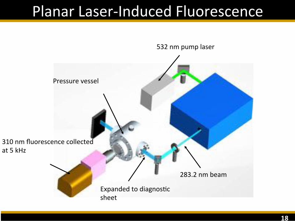
PlanarLaser-InducedFluorescence
283.2nmbeam
ExpandedtodiagnosFcsheet
532nmpumplaser
Pressurevessel
310nmfluorescencecollectedat5kHz

19
InSituFlameVisualizaFon
• OHPLIFhasrecentlybeenappliedinsitutopropellantsinourgroup(BobLuchtcollaborator)
• Wecannowimagetheflamestructures! A:Oxidizerreleasedintoafuel-richgasphase
B:RecessedAPburningfasterthansurroundingmixture.Resultisliced,overvenFlatedflame.
20
CatalyzedPropellant

21
§ Metals and metalloids have been widely used as neat elemental fuels
§ Modifying and tuning the combustion characteristics of these fuels remains challenging
21
Metallized Fuels
§ Can modify reactivity through particle size reduction or surface modification/functionalization (drawbacks)
§ Howonecanobtaintheadvantagesofnanoscalefuelswithoutthedrawbacks?
Major Drawbacks to nanoscale and nanoporous materials • High Cost • Difficulty of synthesis (e.g., strong acids, scalability) • High specific surface area (SSA)
• Processing issues (unfavorable rheology) • Rapid oxidation and aging
2222
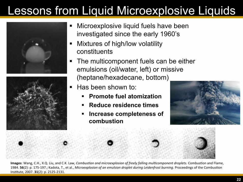
Lessons from Liquid Microexplosive Liquids § Microexplosive liquid fuels have been
investigated since the early 1960’s § Mixtures of high/low volatility
constituents § The multicomponent fuels can be either
emulsions (oil/water, left) or missive (heptane/hexadecane, bottom)
§ Has been shown to: § Promote fuel atomization § Reduce residence times § Increase completeness of
combustion
Images:Wang,C.H.,X.Q.Liu,andC.K.Law,Combus'onandmicroexplosionoffreelyfallingmul'componentdroplets.CombusFonandFlame,1984.56(2):p.175-197.;Kadota,T.,etal.,MicroexplosionofanemulsiondropletduringLeidenfrostburning.ProceedingsoftheCombusFonInsFtute,2007.31(2):p.2125-2131.

23
Wehavebeenresearchingmicron-scalemetallizedfuelpar:cles/dropletscanhavesimilarproper:estoliquid
fueldropletsthatmicroexplode
23
Analogies to Metallized Microexplosive Fuels
Emulsion Fuels • Mechanical activation
(MA, ball milling) can create composite particles with nanometric inclusion material (e.g., polymer)
Missive Fuels • Metal alloys can yield
particles that have constituents mixed at the molecular scale
Constituents Nanocomposite Particle New Phase Solid Solution
RightImages:hlp://www.spaceflight.esa.int/impress/text/educaFon/Images/SolidificaFon/Intermetallics/Intermetallic%20versus%20alloy.jpg

2424
Mechanical Activation
§ Have been shown to: § Modify reactivity § Alter combustion products
(e.g., morphology, composition, etc.) § Affect the completeness of
combustion § Micron-scale morphologies
(moderate SSA) § Can be tailored to achieve desired
material properties and combustion characteristics
Inclusion materials can be interacting or non-interacting
Imagesmodifiedfrom:Sippel,T.R.,S.F.Son,andL.J.Groven,ModifyingAluminumReac'vitywithPoly(CarbonMonofluoride)viaMechanicalAc'va'on.PropellantsExplosivesPyrotechnics,2013.38(3):p.321-326.
C
F
Al
25
MA Powders – Solid Propellant
25
Nea
t Alu
min
um
MA
Al/P
TFE
Images:Sippel,T.R.,S.F.Son,andL.J.Groven,Aluminumagglomera'onreduc'oninacompositepropellantusingtailoredAl/PTFEpar'cles.CombusFonandFlame,2013(0).
Neat Aluminum MA 70/30 Al/PTFE
2626
Theoretical Calculations 80/20 Al-Li Alloy Neat Al
Al2O3
Al2O3 AND LiCl
Max ISP ΔhChamber-Exit Temperature Molecular Weight Cl → HCl[sec] [kJ g-1] [K] [kg kmol-1] [%]
Neat Al 264.8 3.4 3614 27.9 98.3Neat Li 263.4 3.3 3204 27.3 1.8
80/20 Al-Li 271.9 3.6 3553 26.2 1.9
Additive
2727
Al-Li Alloy: Theoretical Performance
• Ideal: 16.9% Li (at 85% Solids Loading) • 20% Li powder is ~stable and commercially available
High HPHS
28
Alloy Powders – Solid Propellant (1000 fps)
28
26.80/61.48/11.72 Metal/AP/HTPB
Neat Al 80/20 Al-Li Alloy
Appears to be less coarse product agglomeration from the Al-Li propellant

29
Alloy Powders – Propellant Surface (9900 fps)
29
80/20 Al-Li Alloy Neat Al
Aluminum sinters and agglomerates on the
propellant surface
Al-Li forms a surface melt layer, and the Al-Li droplets
appear to microexplode

30
Alloy Powders – Shattering Microexplosion
30
The lithium boils within the molten Al-Li, shattering the liquid droplets
AP P
ropellant C
O2 Laser in A
ir (213 W
cm-2)

31
MA Powders – Microexplosion Mechanism
31
32
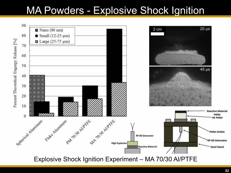
MA Powders - Explosive Shock Ignition
32
Explosive Shock Ignition Experiment – MA 70/30 Al/PTFE
33
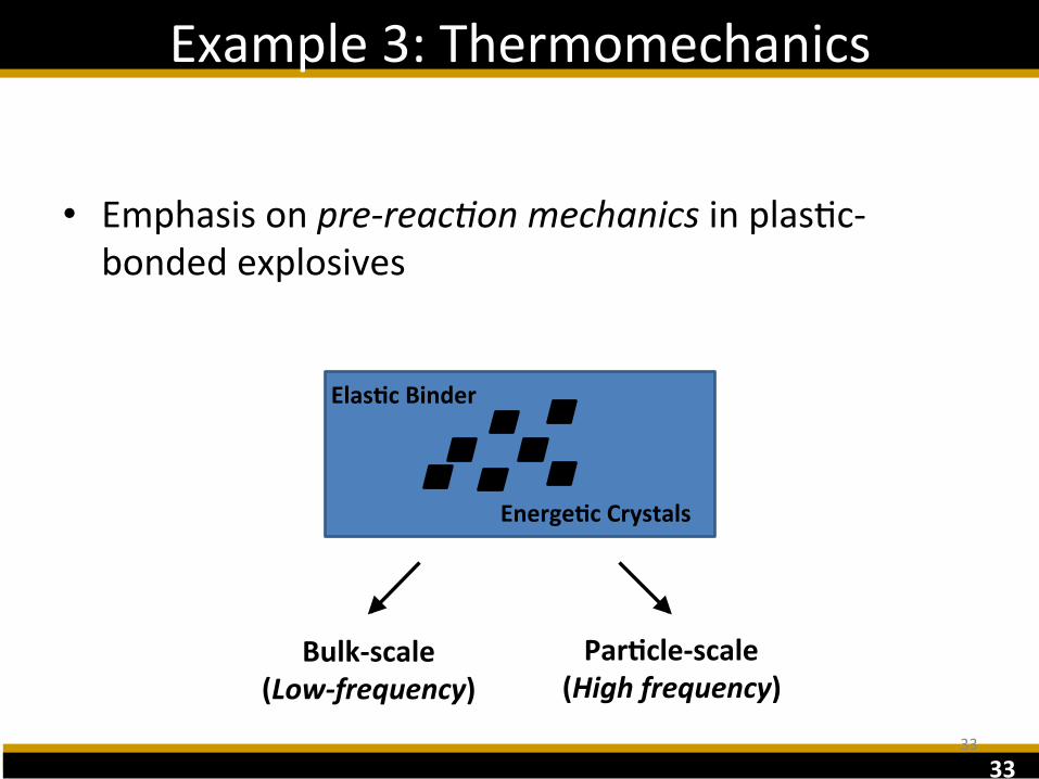
Example3:Thermomechanics
• Emphasisonpre-reac'onmechanicsinplasFc-bondedexplosives
33
Bulk-scale(Low-frequency)
Par:cle-scale(Highfrequency)
Elas:cBinder
Energe:cCrystals
34
TheTakeaway
• Atthebulk-scale:– Homogenizedmaterialmodelsappeartosuffice– Thethermomechanicsappeartobeclassical– Aginganddamageappeartodominatetheresponse
• Atthepar'cle-scale:– DetailedparFcle-scalemodelsnecessary– Hot-spotthermomechanicsrelevant– WeakexcitaFonscanhavedramaFceffectsduetoenergyconcentra'on
34
35
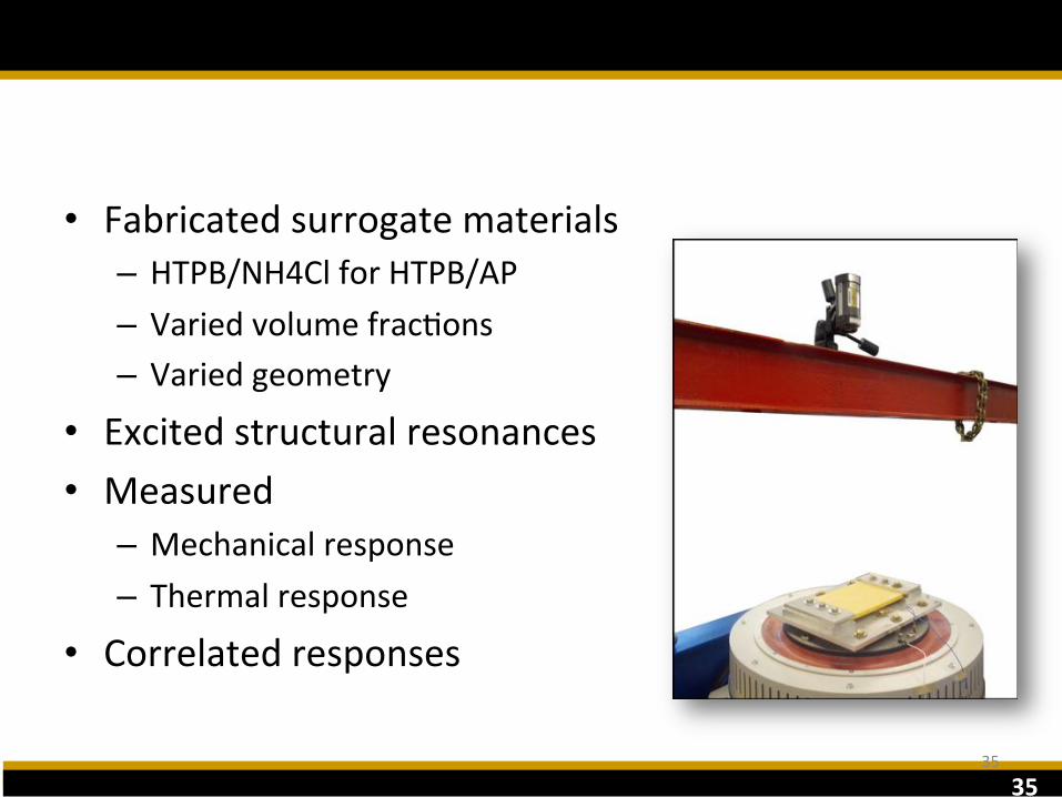
Bulk-ScaleThermomechanics
• Fabricatedsurrogatematerials– HTPB/NH4ClforHTPB/AP– VariedvolumefracFons– Variedgeometry
• Excitedstructuralresonances• Measured
– Mechanicalresponse– Thermalresponse
• Correlatedresponses
35
36
ParFcle-ScaleThermomechanics
36
37
ParFcle-ScaleThermomechanics
37
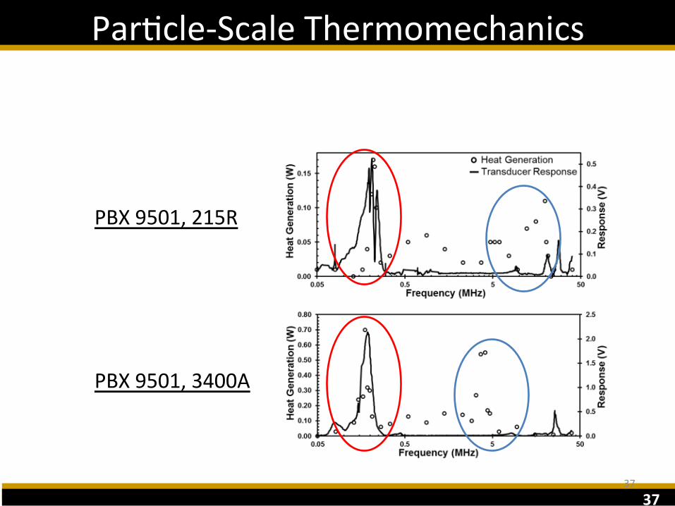
PBX9501,215R
PBX9501,3400A
38
ParFcle-ScaleThermomechanics
38
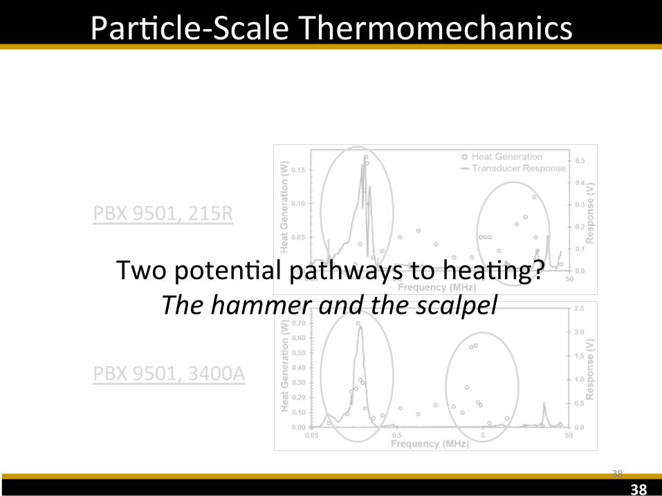
PBX9501,215R
PBX9501,3400A
TwopotenFalpathwaystoheaFng?Thehammerandthescalpel

39
ParFcle-ScaleThermomechanics
39
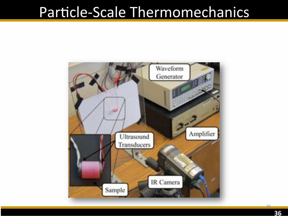
• Sylgard184embeddedwithvariousenergeFcandinertparFcles– 4.0x6.7x9.0mm– ParFcles~1.0mmbeneathsurface
• Piezoelectricultrasonictransducersepoxiedtoeachsample– RadialexcitaFon– 215kHzresonance

40
ParFcle-ScaleThermomechanics
40
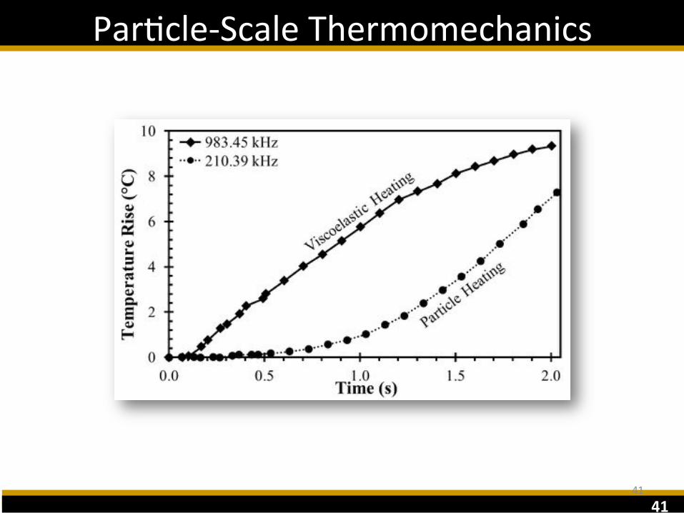
210.39kHz 983.45kHz
41
ParFcle-ScaleThermomechanics
41

42
ParFcle-ScaleThermomechanics
42
AP(550-700μm)sampleat10Walsofsuppliedelectricalpowerat215kHz.TotalFmetoigniFon~8seconds.

43
ParFcle-ScaleThermomechanicalInteracFons
43

44
Trace ExplosivesDetecFonResearchatPurdue
SteveBeaudoin
ProfessorofChemicalEngineeringAcademicDirector,TeachingandLearningTechnology
PurdueUniversityWestLafayePe,[email protected]
45
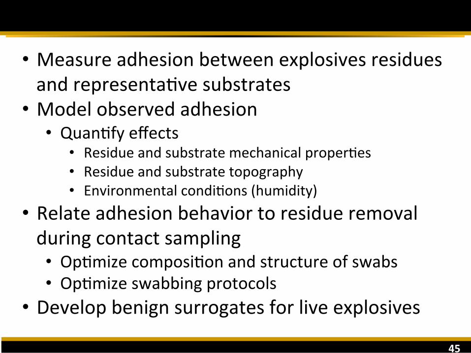
Overall Goals
• MeasureadhesionbetweenexplosivesresiduesandrepresentaFvesubstrates
• Modelobservedadhesion• QuanFfyeffects
• ResidueandsubstratemechanicalproperFes• Residueandsubstratetopography• EnvironmentalcondiFons(humidity)
• Relateadhesionbehaviortoresidueremovalduringcontactsampling• OpFmizecomposiFonandstructureofswabs• OpFmizeswabbingprotocols
• Developbenignsurrogatesforliveexplosives

46
Viscous effects
Surface effects
Historical Model: Composite Deformation
"#$↑∗ = '↓1 + '↓2 )*↑+
)*= ,- ↓* .↓32 /γcos0
Iveson, S. M., & Page, N. W. (2004). Brittle to Plastic Transition in the Dynamic Mechanical Behavior of Partially Saturated Granular Materials. Journal of Applied Mechanics, 71(4), 470–475.
Peak flow stress
Surface effects
"#$↑∗ = 1↓2 .↓32 /γcos0

47
106
105
104
103
102
101
100
Simulated Explosives
1.E-06 1.E-04 1.E-02 1.E+00 1.E+02 1.E+04 1.E+06
Dim
ensi
onle
ss p
eak
flow
stre
ss, (
-)
Capillary number (-)
)*= viscous effects/surface effects
"#$↑∗ = peak Alow stress/surface effects
BehaviorconsistentwithexisFngtheory

48
Viscosity of Explosives Binders
0
150
300
450
0 20 40 60 80 100
Visc
osity
(Pa*
s)
Shear rate (1/s)
0
500
1000
1500
2000
2500
0.0 2.5 5.0 7.5 10.0
Visc
osity
(Pa*
s)
Shear rate (1/s)
Semtex H binder
C-4 binder
49
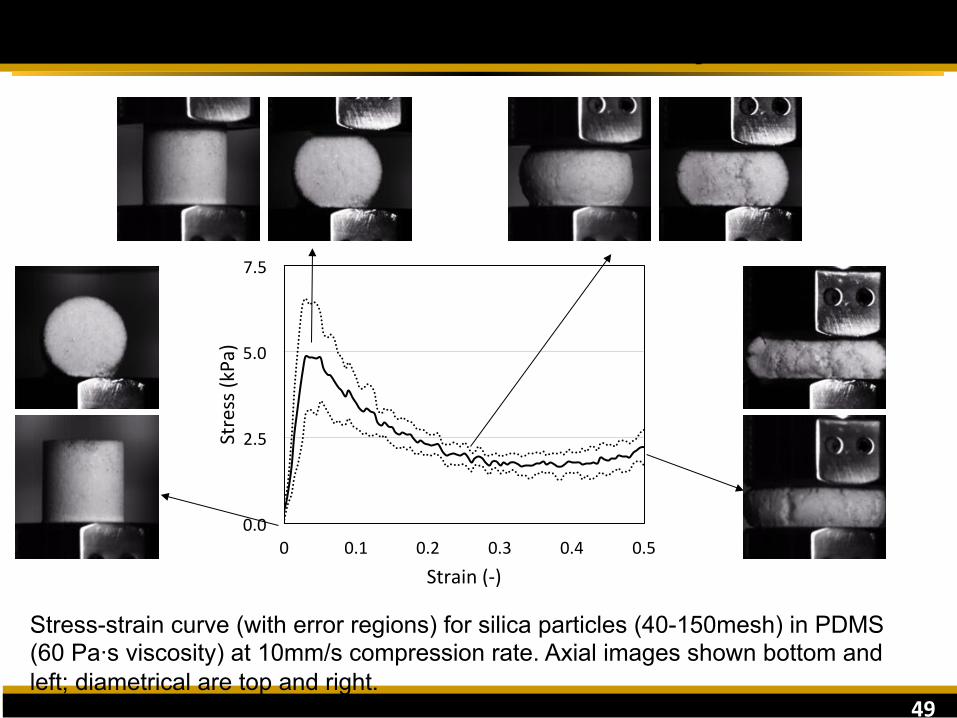
Deformation of Simulated Explosive
0.0
2.5
5.0
7.5
0 0.1 0.2 0.3 0.4 0.5
Stress(kPa)
Strain(-)
Stress-strain curve (with error regions) for silica particles (40-150mesh) in PDMS (60 Pa·s viscosity) at 10mm/s compression rate. Axial images shown bottom and left; diametrical are top and right.

50
Comparison to Live C-4
Stress-strain curves (with error regions) for live C-4 (left) and silica particles in simulated C-4 binder (right) at 1mm/s, 10mm/s, and 100mm/s compression rates.
• Shape of profile for simulant matches that of live material • Ongoing work: Vary particle size distribution in simulant to match magnitude of
stress response
w 100mm/s
10mm/s 1mm/s

51
Explosives Adhesion
AdhesionbetweenRDXandcoatedaluminumsubstrates
AdhesionbetweenTNTandcoatedaluminumsubstrates

52
Novel Swabs for Contact Sampling
10 µm
10 µm
10 µm
SEMimagesofpolypyrrolepillarsofvaryingaspectraFo.Thedimensionsofthepillarscanbeeasilytunedbychangingthephotolithographictemplate.

53
Acknowledgements
This material is based upon work supported by the U.S. Department of Homeland Security, Science and Technology Directorate, Office of University Programs, under Grant Award 2013-ST-061-ED0001. The views and conclusions contained in this document are those of the authors and should not be interpreted as
necessarily representing the official policies, either expressed or implied, of the U.S. Department of Homeland Security. [10/2013]
Circled: • Melissa Sweat
• Dec. 2015 • Aaron Harrison
• Dec. 2015 Not pictured: • Johanna Smith
• Grad. May 2014 • Employed at General Mills
• Andrew Parker • Grad. May 2016
• Chris Browne • Grad. May 2017
• Alyssa Bass • Grad. May 2017
54
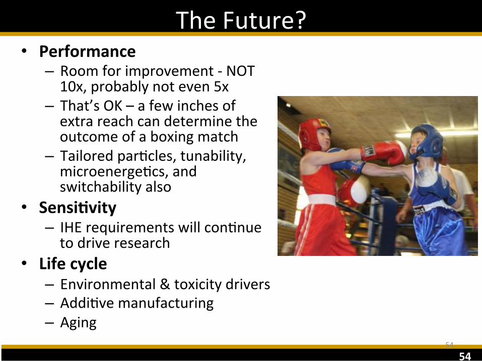
TheFuture?• Performance
– Roomforimprovement-NOT10x,probablynoteven5x
– That’sOK–afewinchesofextrareachcandeterminetheoutcomeofaboxingmatch
– TailoredparFcles,tunability,microenergeFcs,andswitchabilityalso
• Sensi:vity– IHErequirementswillconFnuetodriveresearch
• Lifecycle– Environmental&toxicitydrivers– AddiFvemanufacturing– Aging
54

55
AFOSR,DHS,ARO,ONR,DTRA,NASA,&MDAfundingNSF,NDSEG,SMART,NASAFellowships

56
QuesFons?
562