Embed Size (px)
Citation preview
AN OVERVIEW OF STANDING ROOF SUPPORT PRACTICES AND DEVELOPMENTS IN THE UNITED STATES
Mr. T M Barczak
National Institute for Occupational Safety and Health
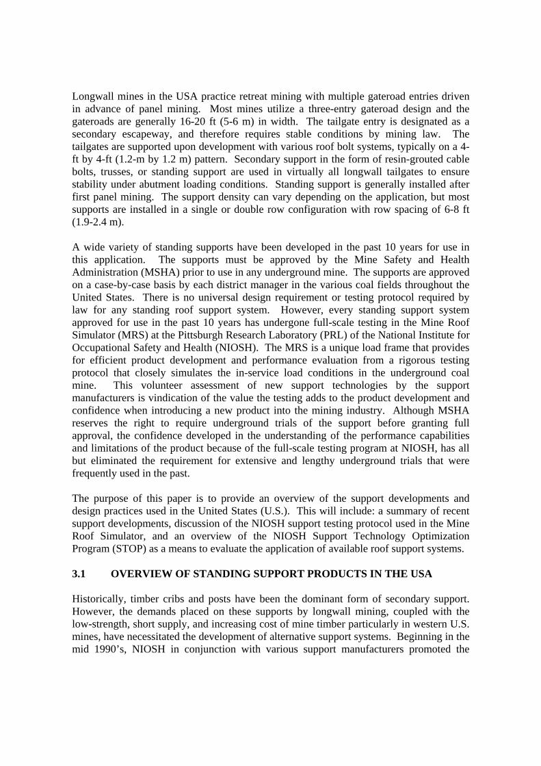
2.1 ABSTRACT
Many of the support concepts currently used in the United States originated in South Africa. These products include the Hercules Crib1, Propsetter, MX Prop, Rocprop, and Spider Prop. Another recent development has been the introduction of hydraulic prestressing units, such as the Jackpot system, to various U.S. standing support systems. Several other prop-type supports with similarities to systems used in South Africa are in use in U.S. coal mines. Some exciting new developments that improve the installation and yield performance of props are also underway. In addition to prop-type supports, crib-type supports and single-unit systems such as the Can support are also frequently utilized in longwall tailgates in the U.S. The goal in U.S. support development is to enhance roof support capability while alleviating material handling barriers to reduce injuries associated with support handling and installation. Support products are generally full-scale tested at the National Institute for Occupational Safety and Health (NIOSH) in the unique Mine Roof Simulator load frame. The performance testing protocol is designed to simulate the full range of load conditions that occur in underground mining to identify the performance deficiencies and limitations of the support products. Once the products complete the performance evaluation, they are implemented into the NIOSH Support Technology Optimization Program (STOP). STOP is a window’s based software program that was developed by NIOSH for facilitating the design of standing roof support systems. STOP has become an industry standard to compare the performance capabilities and facilitate the application of these support products into various mining conditions. The purpose of this paper is to provide an overview of the support design and application philosophy in the United States. 2.1 INTRODUCTION The United States of America (USA) is the second leading coal producing country in the world, producing approximately 1.1 billion short tons in 2004, approximately 33 pct of which is produced in underground coal mines (U.S. Mine Safety and Health Administration, 2004). Productivity has improved steadily over the past 25 years, largely due to the efficiency of longwall mining operations. In 2004, there were 46 longwall operations, which produced 52 pct of the underground coal. Thirty percent of the longwall operations are producing over 5 million tons of coal a year. Two longwall operations produced over 10 million tons in 2004.
1Mention of company name or product does not constitute endorsement by the National Institute for Occupational Safety and Health.
Longwall mines in the USA practice retreat mining with multiple gateroad entries driven in advance of panel mining. Most mines utilize a three-entry gateroad design and the gateroads are generally 16-20 ft (5-6 m) in width. The tailgate entry is designated as a secondary escapeway, and therefore requires stable conditions by mining law. The tailgates are supported upon development with various roof bolt systems, typically on a 4-ft by 4-ft (1.2-m by 1.2 m) pattern. Secondary support in the form of resin-grouted cable bolts, trusses, or standing support are used in virtually all longwall tailgates to ensure stability under abutment loading conditions. Standing support is generally installed after first panel mining. The support density can vary depending on the application, but most supports are installed in a single or double row configuration with row spacing of 6-8 ft (1.9-2.4 m). A wide variety of standing supports have been developed in the past 10 years for use in this application. The supports must be approved by the Mine Safety and Health Administration (MSHA) prior to use in any underground mine. The supports are approved on a case-by-case basis by each district manager in the various coal fields throughout the United States. There is no universal design requirement or testing protocol required by law for any standing roof support system. However, every standing support system approved for use in the past 10 years has undergone full-scale testing in the Mine Roof Simulator (MRS) at the Pittsburgh Research Laboratory (PRL) of the National Institute for Occupational Safety and Health (NIOSH). The MRS is a unique load frame that provides for efficient product development and performance evaluation from a rigorous testing protocol that closely simulates the in-service load conditions in the underground coal mine. This volunteer assessment of new support technologies by the support manufacturers is vindication of the value the testing adds to the product development and confidence when introducing a new product into the mining industry. Although MSHA reserves the right to require underground trials of the support before granting full approval, the confidence developed in the understanding of the performance capabilities and limitations of the product because of the full-scale testing program at NIOSH, has all but eliminated the requirement for extensive and lengthy underground trials that were frequently used in the past. The purpose of this paper is to provide an overview of the support developments and design practices used in the United States (U.S.). This will include: a summary of recent support developments, discussion of the NIOSH support testing protocol used in the Mine Roof Simulator, and an overview of the NIOSH Support Technology Optimization Program (STOP) as a means to evaluate the application of available roof support systems. 3.1 OVERVIEW OF STANDING SUPPORT PRODUCTS IN THE USA Historically, timber cribs and posts have been the dominant form of secondary support. However, the demands placed on these supports by longwall mining, coupled with the low-strength, short supply, and increasing cost of mine timber particularly in western U.S. mines, have necessitated the development of alternative support systems. Beginning in the mid 1990’s, NIOSH in conjunction with various support manufacturers promoted the
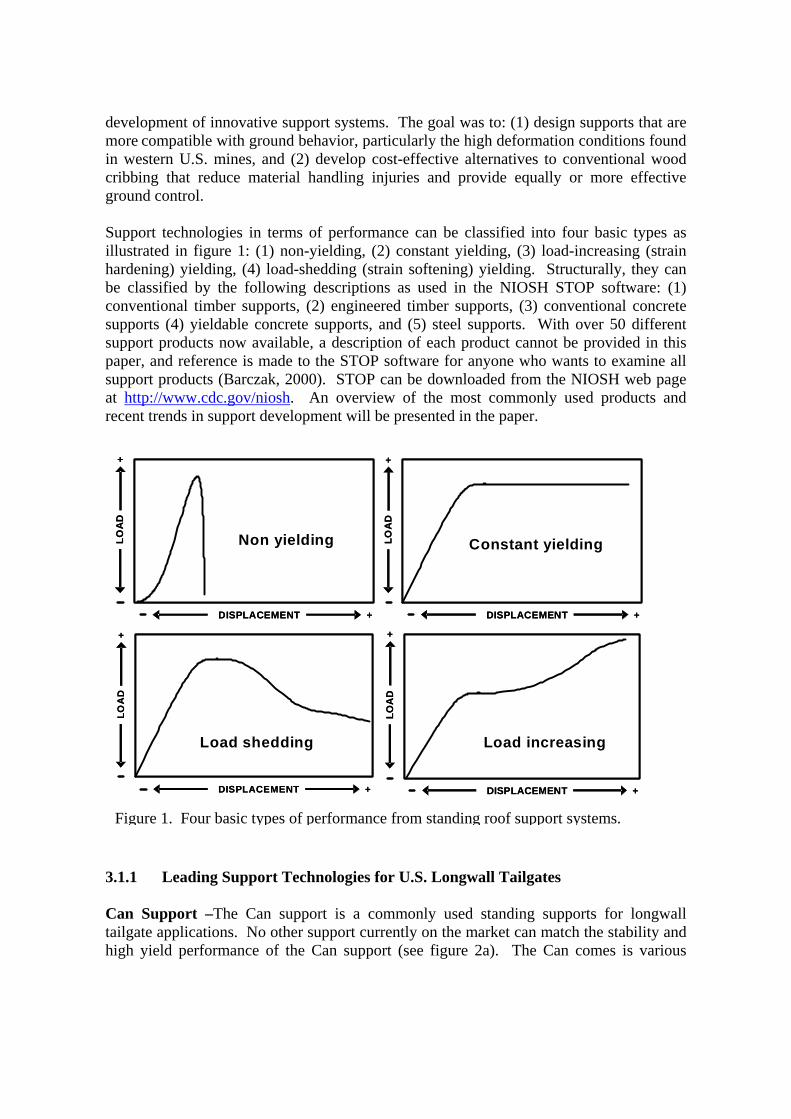
development of innovative support systems. The goal was to: (1) design supports that are more compatible with ground behavior, particularly the high deformation conditions found in western U.S. mines, and (2) develop cost-effective alternatives to conventional wood cribbing that reduce material handling injuries and provide equally or more effective ground control. Support technologies in terms of performance can be classified into four basic types as illustrated in figure 1: (1) non-yielding, (2) constant yielding, (3) load-increasing (strain hardening) yielding, (4) load-shedding (strain softening) yielding. Structurally, they can be classified by the following descriptions as used in the NIOSH STOP software: (1) conventional timber supports, (2) engineered timber supports, (3) conventional concrete supports (4) yieldable concrete supports, and (5) steel supports. With over 50 different support products now available, a description of each product cannot be provided in this paper, and reference is made to the STOP software for anyone who wants to examine all support products (Barczak, 2000). STOP can be downloaded from the NIOSH web page at http://www.cdc.gov/niosh. An overview of the most commonly used products and recent trends in support development will be presented in the paper.
3.1.1 Leading Support Technologies for U.S. Longwall Tailgates Can Support –The Can support is a commonly used standing supports for longwall tailgate applications. No other support currently on the market can match the stability and high yield performance of the Can support (see figure 2a). The Can comes is various
Figure 1. Four basic types of performance from standing roof support systems.
DISPLACEMENT
LOA
D
+
+
DISPLACEMENT
LOA
D
+
+
DISPLACEMENT
LOA
D
+
+
DISPLACEMENT
LOA
D
+
+
DISPLACEMENT
LOA
D
+
+
DISPLACEMENT
LOA
D
+
+
DISPLACEMENT
LOA
D
+
+
DISPLACEMENT
LOA
D
+
+
Non yielding Constant yielding
Load shedding Load increasing
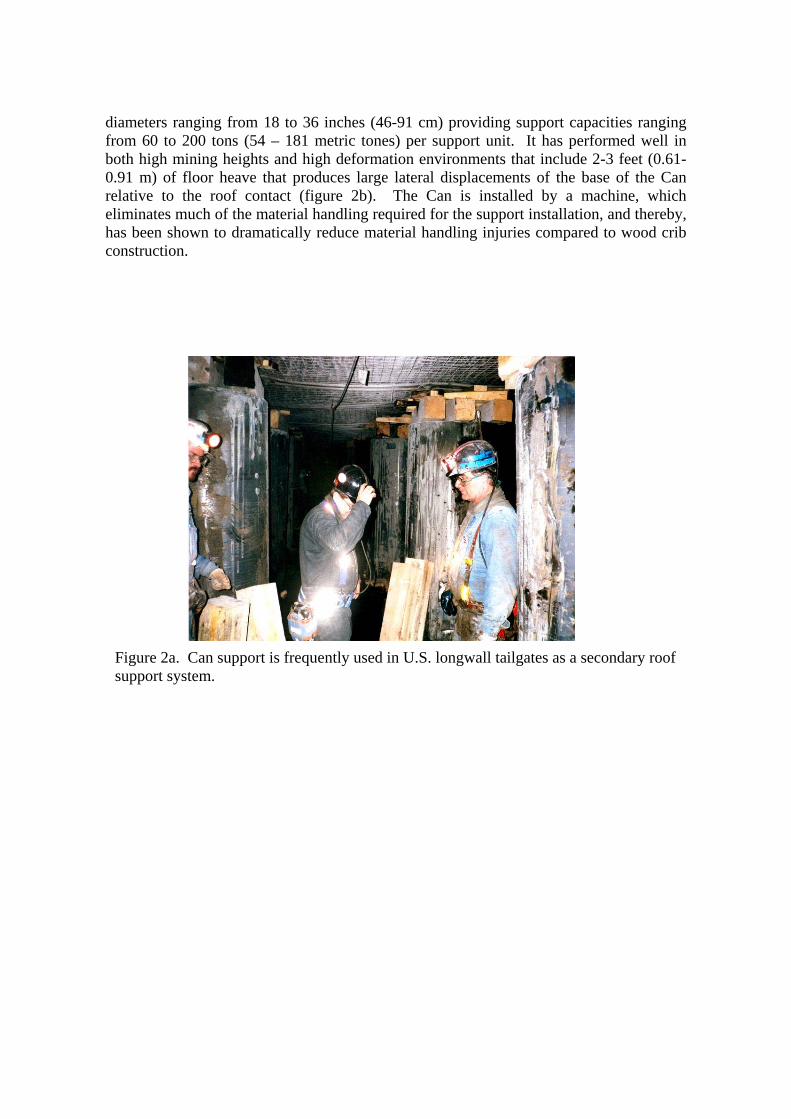
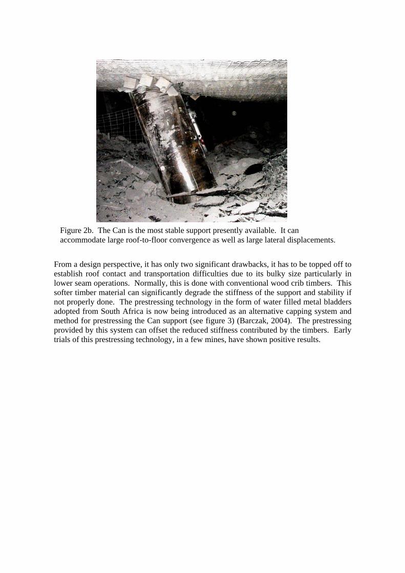
diameters ranging from 18 to 36 inches (46-91 cm) providing support capacities ranging from 60 to 200 tons (54 – 181 metric tones) per support unit. It has performed well in both high mining heights and high deformation environments that include 2-3 feet (0.61-0.91 m) of floor heave that produces large lateral displacements of the base of the Can relative to the roof contact (figure 2b). The Can is installed by a machine, which eliminates much of the material handling required for the support installation, and thereby, has been shown to dramatically reduce material handling injuries compared to wood crib construction.
Figure 2a. Can support is frequently used in U.S. longwall tailgates as a secondary roof support system.
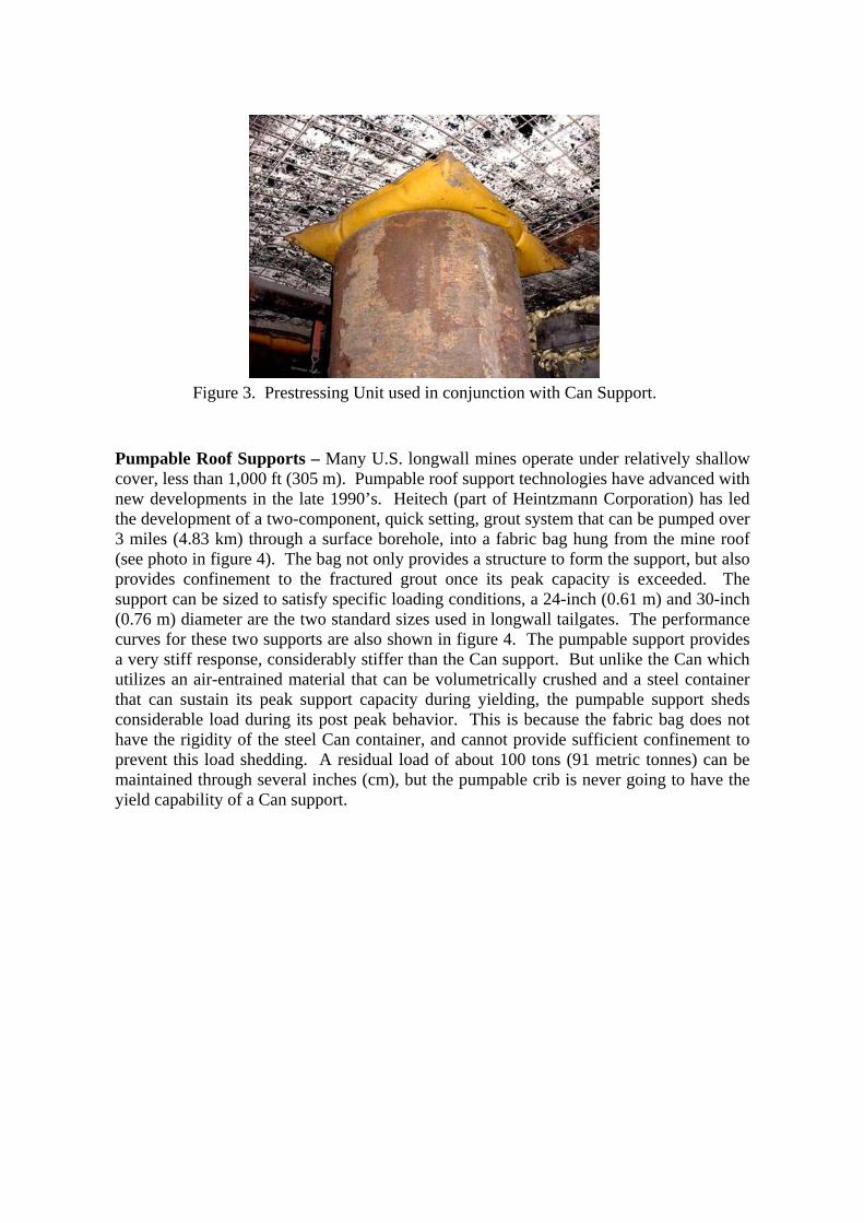
From a design perspective, it has only two significant drawbacks, it has to be topped off to establish roof contact and transportation difficulties due to its bulky size particularly in lower seam operations. Normally, this is done with conventional wood crib timbers. This softer timber material can significantly degrade the stiffness of the support and stability if not properly done. The prestressing technology in the form of water filled metal bladders adopted from South Africa is now being introduced as an alternative capping system and method for prestressing the Can support (see figure 3) (Barczak, 2004). The prestressing provided by this system can offset the reduced stiffness contributed by the timbers. Early trials of this prestressing technology, in a few mines, have shown positive results.
Figure 2b. The Can is the most stable support presently available. It can accommodate large roof-to-floor convergence as well as large lateral displacements.
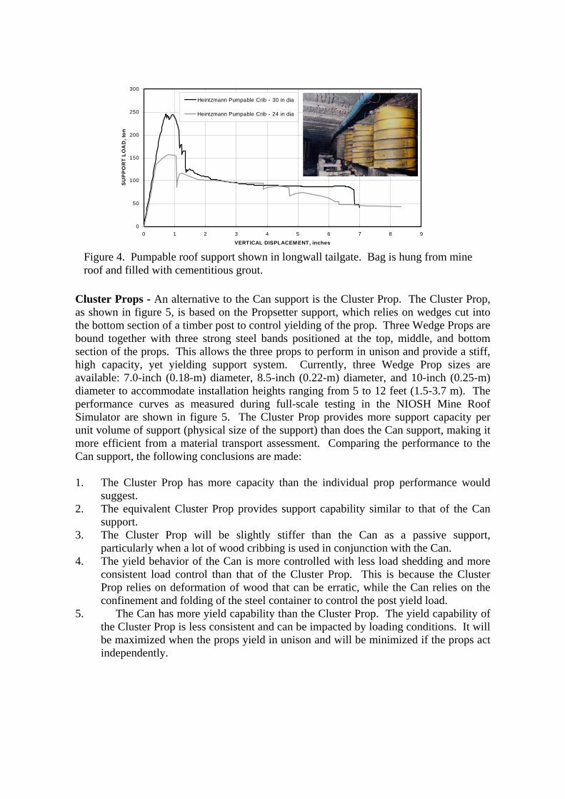
Pumpable Roof Supports – Many U.S. longwall mines operate under relatively shallow cover, less than 1,000 ft (305 m). Pumpable roof support technologies have advanced with new developments in the late 1990’s. Heitech (part of Heintzmann Corporation) has led the development of a two-component, quick setting, grout system that can be pumped over 3 miles (4.83 km) through a surface borehole, into a fabric bag hung from the mine roof (see photo in figure 4). The bag not only provides a structure to form the support, but also provides confinement to the fractured grout once its peak capacity is exceeded. The support can be sized to satisfy specific loading conditions, a 24-inch (0.61 m) and 30-inch (0.76 m) diameter are the two standard sizes used in longwall tailgates. The performance curves for these two supports are also shown in figure 4. The pumpable support provides a very stiff response, considerably stiffer than the Can support. But unlike the Can which utilizes an air-entrained material that can be volumetrically crushed and a steel container that can sustain its peak support capacity during yielding, the pumpable support sheds considerable load during its post peak behavior. This is because the fabric bag does not have the rigidity of the steel Can container, and cannot provide sufficient confinement to prevent this load shedding. A residual load of about 100 tons (91 metric tonnes) can be maintained through several inches (cm), but the pumpable crib is never going to have the yield capability of a Can support.
Figure 3. Prestressing Unit used in conjunction with Can Support.
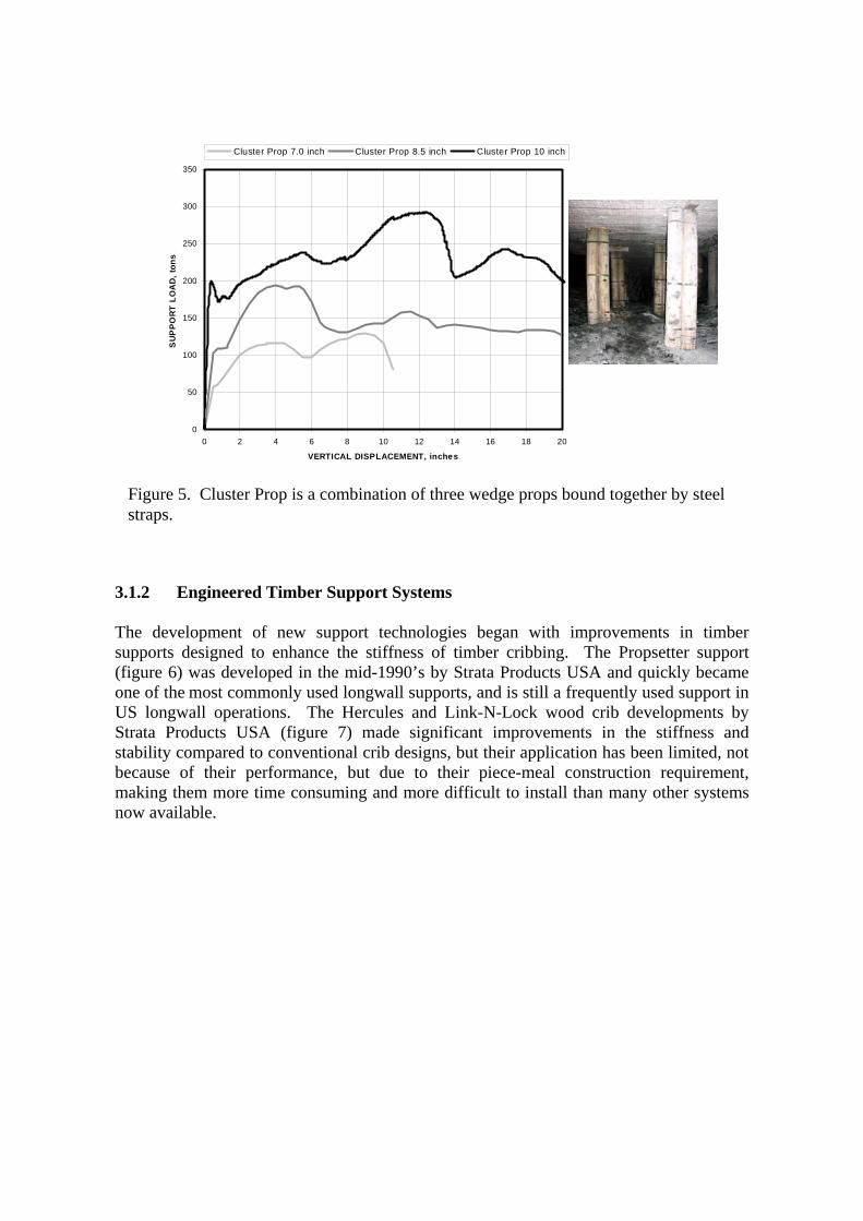
Cluster Props - An alternative to the Can support is the Cluster Prop. The Cluster Prop, as shown in figure 5, is based on the Propsetter support, which relies on wedges cut into the bottom section of a timber post to control yielding of the prop. Three Wedge Props are bound together with three strong steel bands positioned at the top, middle, and bottom section of the props. This allows the three props to perform in unison and provide a stiff, high capacity, yet yielding support system. Currently, three Wedge Prop sizes are available: 7.0-inch (0.18-m) diameter, 8.5-inch (0.22-m) diameter, and 10-inch (0.25-m) diameter to accommodate installation heights ranging from 5 to 12 feet (1.5-3.7 m). The performance curves as measured during full-scale testing in the NIOSH Mine Roof Simulator are shown in figure 5. The Cluster Prop provides more support capacity per unit volume of support (physical size of the support) than does the Can support, making it more efficient from a material transport assessment. Comparing the performance to the Can support, the following conclusions are made: 1. The Cluster Prop has more capacity than the individual prop performance would
suggest. 2. The equivalent Cluster Prop provides support capability similar to that of the Can
support. 3. The Cluster Prop will be slightly stiffer than the Can as a passive support,
particularly when a lot of wood cribbing is used in conjunction with the Can. 4. The yield behavior of the Can is more controlled with less load shedding and more
consistent load control than that of the Cluster Prop. This is because the Cluster Prop relies on deformation of wood that can be erratic, while the Can relies on the confinement and folding of the steel container to control the post yield load.
5. The Can has more yield capability than the Cluster Prop. The yield capability of the Cluster Prop is less consistent and can be impacted by loading conditions. It will be maximized when the props yield in unison and will be minimized if the props act independently.
Figure 4. Pumpable roof support shown in longwall tailgate. Bag is hung from mine roof and filled with cementitious grout.
0
50
100
150
200
250
300
0 1 2 3 4 5 6 7 8 9
VERTICAL DISPLACEM ENT, inches
SU
PP
OR
T LO
AD
, ton
Heintzmann Pumpable Crib - 30 in dia
Heintzmann Pumpable Crib - 24 in dia
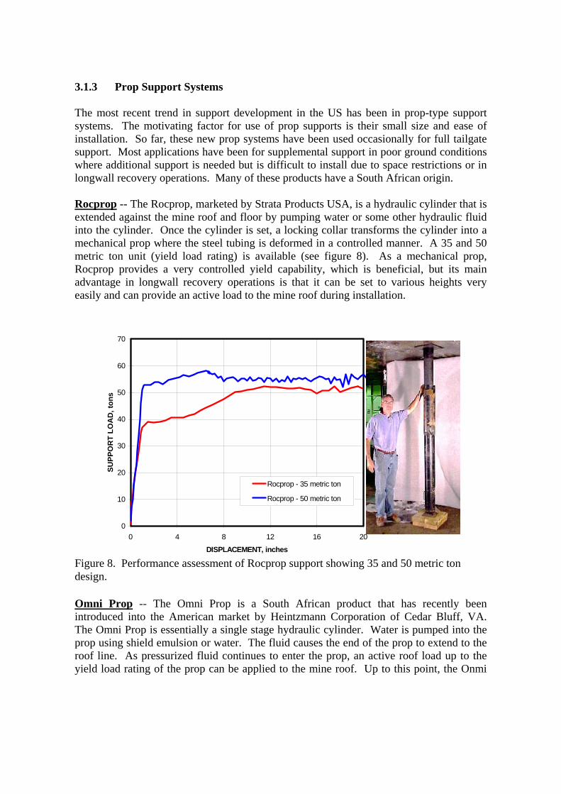
3.1.2 Engineered Timber Support Systems The development of new support technologies began with improvements in timber supports designed to enhance the stiffness of timber cribbing. The Propsetter support (figure 6) was developed in the mid-1990’s by Strata Products USA and quickly became one of the most commonly used longwall supports, and is still a frequently used support in US longwall operations. The Hercules and Link-N-Lock wood crib developments by Strata Products USA (figure 7) made significant improvements in the stiffness and stability compared to conventional crib designs, but their application has been limited, not because of their performance, but due to their piece-meal construction requirement, making them more time consuming and more difficult to install than many other systems now available.
Figure 5. Cluster Prop is a combination of three wedge props bound together by steel straps.
0
50
100
150
200
250
300
350
0 2 4 6 8 10 12 14 16 18 20
VERTICAL DISPLACEMENT, inches
SU
PP
OR
T LO
AD
, ton
s .
Cluster Prop 7.0 inch Cluster Prop 8.5 inch Cluster Prop 10 inch
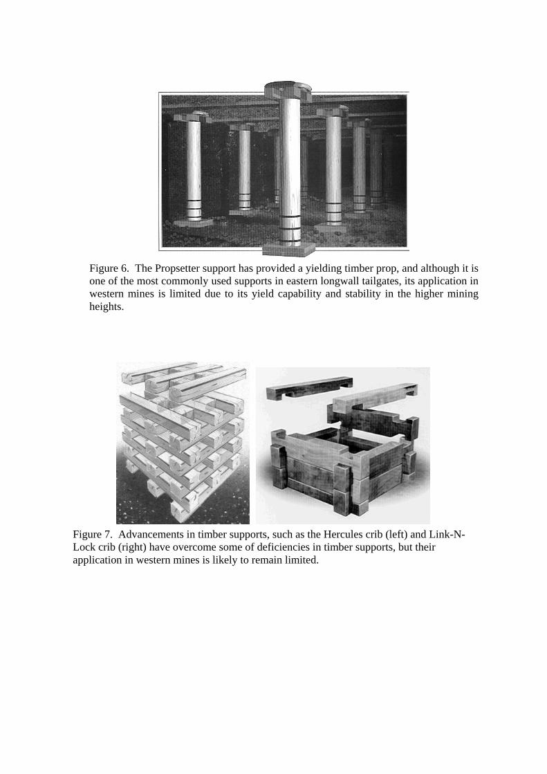
Figure 6. The Propsetter support has provided a yielding timber prop, and although it is one of the most commonly used supports in eastern longwall tailgates, its application in western mines is limited due to its yield capability and stability in the higher mining heights.
Figure 7. Advancements in timber supports, such as the Hercules crib (left) and Link-N-Lock crib (right) have overcome some of deficiencies in timber supports, but their application in western mines is likely to remain limited.
3.1.3 Prop Support Systems The most recent trend in support development in the US has been in prop-type support systems. The motivating factor for use of prop supports is their small size and ease of installation. So far, these new prop systems have been used occasionally for full tailgate support. Most applications have been for supplemental support in poor ground conditions where additional support is needed but is difficult to install due to space restrictions or in longwall recovery operations. Many of these products have a South African origin. Rocprop -- The Rocprop, marketed by Strata Products USA, is a hydraulic cylinder that is extended against the mine roof and floor by pumping water or some other hydraulic fluid into the cylinder. Once the cylinder is set, a locking collar transforms the cylinder into a mechanical prop where the steel tubing is deformed in a controlled manner. A 35 and 50 metric ton unit (yield load rating) is available (see figure 8). As a mechanical prop, Rocprop provides a very controlled yield capability, which is beneficial, but its main advantage in longwall recovery operations is that it can be set to various heights very easily and can provide an active load to the mine roof during installation.
Omni Prop -- The Omni Prop is a South African product that has recently been introduced into the American market by Heintzmann Corporation of Cedar Bluff, VA. The Omni Prop is essentially a single stage hydraulic cylinder. Water is pumped into the prop using shield emulsion or water. The fluid causes the end of the prop to extend to the roof line. As pressurized fluid continues to enter the prop, an active roof load up to the yield load rating of the prop can be applied to the mine roof. Up to this point, the Onmi
0
10
20
30
40
50
60
70
0 4 8 12 16 20
DISPLACEMENT, inches
SUPP
OR
T LO
AD
, ton
s
Rocprop - 35 metric ton
Rocprop - 50 metric ton
Figure 8. Performance assessment of Rocprop support showing 35 and 50 metric ton design.
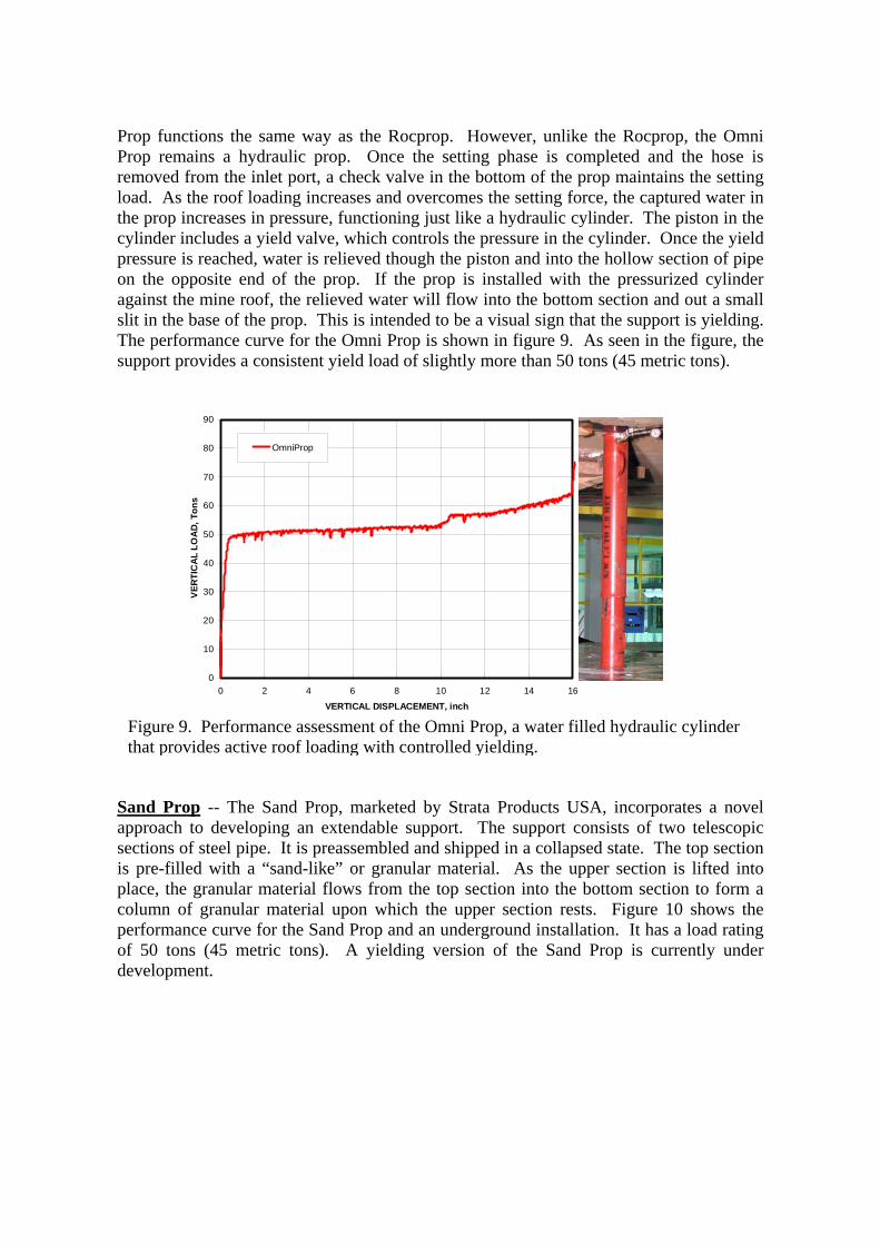
Prop functions the same way as the Rocprop. However, unlike the Rocprop, the Omni Prop remains a hydraulic prop. Once the setting phase is completed and the hose is removed from the inlet port, a check valve in the bottom of the prop maintains the setting load. As the roof loading increases and overcomes the setting force, the captured water in the prop increases in pressure, functioning just like a hydraulic cylinder. The piston in the cylinder includes a yield valve, which controls the pressure in the cylinder. Once the yield pressure is reached, water is relieved though the piston and into the hollow section of pipe on the opposite end of the prop. If the prop is installed with the pressurized cylinder against the mine roof, the relieved water will flow into the bottom section and out a small slit in the base of the prop. This is intended to be a visual sign that the support is yielding. The performance curve for the Omni Prop is shown in figure 9. As seen in the figure, the support provides a consistent yield load of slightly more than 50 tons (45 metric tons).
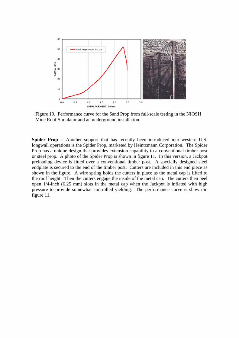
Sand Prop -- The Sand Prop, marketed by Strata Products USA, incorporates a novel approach to developing an extendable support. The support consists of two telescopic sections of steel pipe. It is preassembled and shipped in a collapsed state. The top section is pre-filled with a “sand-like” or granular material. As the upper section is lifted into place, the granular material flows from the top section into the bottom section to form a column of granular material upon which the upper section rests. Figure 10 shows the performance curve for the Sand Prop and an underground installation. It has a load rating of 50 tons (45 metric tons). A yielding version of the Sand Prop is currently under development.
Figure 9. Performance assessment of the Omni Prop, a water filled hydraulic cylinder that provides active roof loading with controlled yielding.
0
10
20
30
40
50
60
70
80
90
0 2 4 6 8 10 12 14 16
VERTICAL DISPLACEMENT, inch
VER
TIC
AL
LOA
D, T
ons
OmniProp
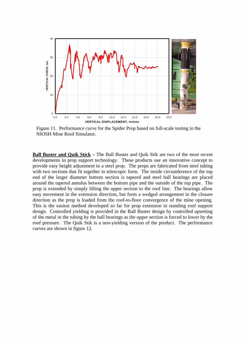
Spider Prop -- Another support that has recently been introduced into western U.S. longwall operations is the Spider Prop, marketed by Heintzmann Corporation. The Spider Prop has a unique design that provides extension capability to a conventional timber post or steel prop. A photo of the Spider Prop is shown in figure 11. In this version, a Jackpot preloading device is fitted over a conventional timber post. A specially designed steel endplate is secured to the end of the timber post. Cutters are included in this end piece as shown in the figure. A wire spring holds the cutters in place as the metal cap is lifted to the roof height. Then the cutters engage the inside of the metal cap. The cutters then peel open 1/4-inch (6.25 mm) slots in the metal cap when the Jackpot is inflated with high pressure to provide somewhat controlled yielding. The performance curve is shown in figure 11.
Figure 10. Performance curve for the Sand Prop from full-scale testing in the NIOSH Mine Roof Simulator and an underground installation.
0
10
20
30
40
50
60
0.0 0.5 1.0 1.5 2.0 2.5 3.0
DISPLACEMENT, inches
LOA
D, t
ons
Sand Prop Model 9-11 ft
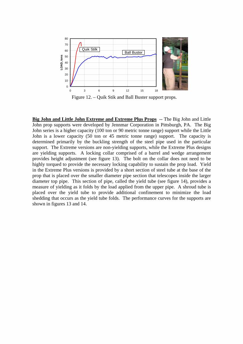
Ball Buster and Quik Stick – The Ball Buster and Quik Stik are two of the most recent developments in prop support technology. These products use an innovative concept to provide easy height adjustment to a steel prop. The props are fabricated from steel tubing with two sections that fit together in telescopic form. The inside circumference of the top end of the larger diameter bottom section is tapered and steel ball bearings are placed around the tapered annulus between the bottom pipe and the outside of the top pipe. The prop is extended by simply lifting the upper section to the roof line. The bearings allow easy movement in the extension direction, but form a wedged arrangement in the closure direction as the prop is loaded from the roof-to-floor convergence of the mine opening. This is the easiest method developed so far for prop extension in standing roof support design. Controlled yielding is provided in the Ball Buster design by controlled upsetting of the metal in the tubing by the ball bearings as the upper section is forced to lower by the roof pressure. The Quik Stik is a non-yielding version of the product. The performance curves are shown in figure 12.
Figure 11. Performance curve for the Spider Prop based on full-scale testing in the NIOSH Mine Roof Simulator.
0
10
20
30
40
0.0 2.0 4.0 6.0 8.0 10.0 12.0 14.0 16.0 18.0 20.0
VERTICAL DISPLACEMENT, inches
VE
RTI
CA
L FO
RC
E, t
on
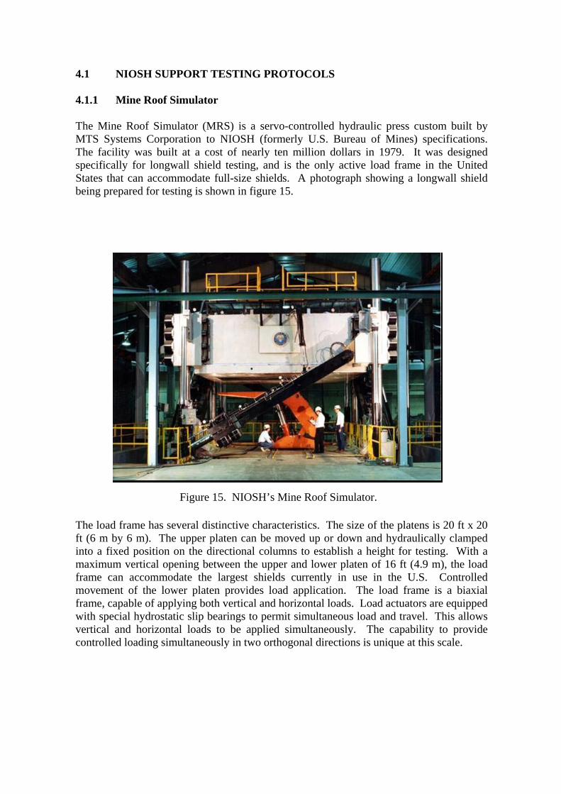
Big John and Little John Extreme and Extreme Plus Props -- The Big John and Little John prop supports were developed by Jennmar Corporation in Pittsburgh, PA. The Big John series is a higher capacity (100 ton or 90 metric tonne range) support while the Little John is a lower capacity (50 ton or 45 metric tonne range) support. The capacity is determined primarily by the buckling strength of the steel pipe used in the particular support. The Extreme versions are non-yielding supports, while the Extreme Plus designs are yielding supports. A locking collar comprised of a barrel and wedge arrangement provides height adjustment (see figure 13). The bolt on the collar does not need to be highly torqued to provide the necessary locking capability to sustain the prop load. Yield in the Extreme Plus versions is provided by a short section of steel tube at the base of the prop that is placed over the smaller diameter pipe section that telescopes inside the larger diameter top pipe. This section of pipe, called the yield tube (see figure 14), provides a measure of yielding as it folds by the load applied from the upper pipe. A shroud tube is placed over the yield tube to provide additional confinement to minimize the load shedding that occurs as the yield tube folds. The performance curves for the supports are shown in figures 13 and 14.
Figure 12. – Quik Stik and Ball Buster support props.
0
10
20
30
40
50
60
70
80
0 3 6 9 12 15 18
LOA
D, t
ons
Quik Stilk Ball Buster
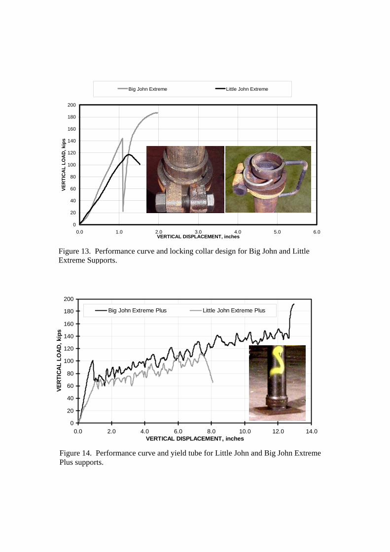
Figure 14. Performance curve and yield tube for Little John and Big John Extreme Plus supports.
0
20
40
60
80
100
120
140
160
180
200
0.0 2.0 4.0 6.0 8.0 10.0 12.0 14.0VERTICAL DISPLACEMENT, inches
VER
TIC
AL
LOA
D, k
ips
Big John Extreme Plus Little John Extreme Plus
Figure 13. Performance curve and locking collar design for Big John and Little Extreme Supports.
0
20
40
60
80
100
120
140
160
180
200
0.0 1.0 2.0 3.0 4.0 5.0 6.0VERTICAL DISPLACEMENT, inches
VER
TIC
AL
LOA
D, k
ips
Big John Extreme Little John Extreme
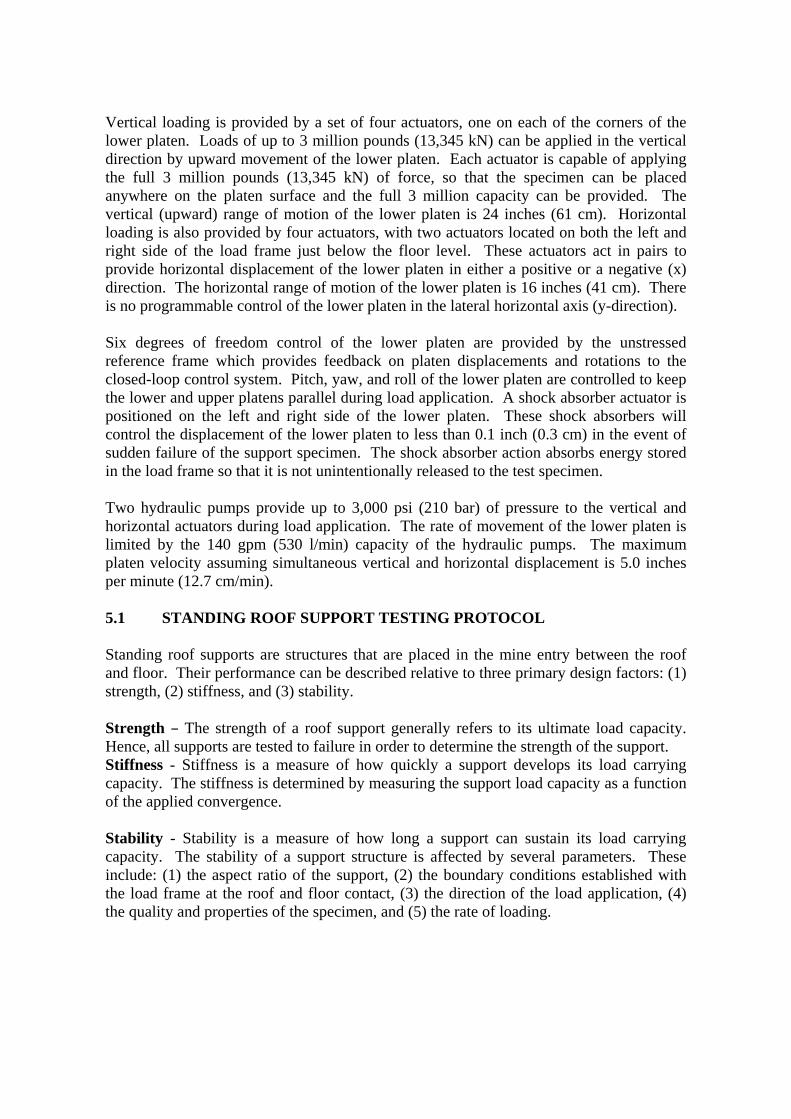
4.1 NIOSH SUPPORT TESTING PROTOCOLS 4.1.1 Mine Roof Simulator The Mine Roof Simulator (MRS) is a servo-controlled hydraulic press custom built by MTS Systems Corporation to NIOSH (formerly U.S. Bureau of Mines) specifications. The facility was built at a cost of nearly ten million dollars in 1979. It was designed specifically for longwall shield testing, and is the only active load frame in the United States that can accommodate full-size shields. A photograph showing a longwall shield being prepared for testing is shown in figure 15.
The load frame has several distinctive characteristics. The size of the platens is 20 ft x 20 ft (6 m by 6 m). The upper platen can be moved up or down and hydraulically clamped into a fixed position on the directional columns to establish a height for testing. With a maximum vertical opening between the upper and lower platen of 16 ft (4.9 m), the load frame can accommodate the largest shields currently in use in the U.S. Controlled movement of the lower platen provides load application. The load frame is a biaxial frame, capable of applying both vertical and horizontal loads. Load actuators are equipped with special hydrostatic slip bearings to permit simultaneous load and travel. This allows vertical and horizontal loads to be applied simultaneously. The capability to provide controlled loading simultaneously in two orthogonal directions is unique at this scale.
Figure 15. NIOSH’s Mine Roof Simulator.
Vertical loading is provided by a set of four actuators, one on each of the corners of the lower platen. Loads of up to 3 million pounds (13,345 kN) can be applied in the vertical direction by upward movement of the lower platen. Each actuator is capable of applying the full 3 million pounds (13,345 kN) of force, so that the specimen can be placed anywhere on the platen surface and the full 3 million capacity can be provided. The vertical (upward) range of motion of the lower platen is 24 inches (61 cm). Horizontal loading is also provided by four actuators, with two actuators located on both the left and right side of the load frame just below the floor level. These actuators act in pairs to provide horizontal displacement of the lower platen in either a positive or a negative (x) direction. The horizontal range of motion of the lower platen is 16 inches (41 cm). There is no programmable control of the lower platen in the lateral horizontal axis (y-direction). Six degrees of freedom control of the lower platen are provided by the unstressed reference frame which provides feedback on platen displacements and rotations to the closed-loop control system. Pitch, yaw, and roll of the lower platen are controlled to keep the lower and upper platens parallel during load application. A shock absorber actuator is positioned on the left and right side of the lower platen. These shock absorbers will control the displacement of the lower platen to less than 0.1 inch (0.3 cm) in the event of sudden failure of the support specimen. The shock absorber action absorbs energy stored in the load frame so that it is not unintentionally released to the test specimen. Two hydraulic pumps provide up to 3,000 psi (210 bar) of pressure to the vertical and horizontal actuators during load application. The rate of movement of the lower platen is limited by the 140 gpm (530 l/min) capacity of the hydraulic pumps. The maximum platen velocity assuming simultaneous vertical and horizontal displacement is 5.0 inches per minute (12.7 cm/min). 5.1 STANDING ROOF SUPPORT TESTING PROTOCOL
Standing roof supports are structures that are placed in the mine entry between the roof and floor. Their performance can be described relative to three primary design factors: (1) strength, (2) stiffness, and (3) stability. Strength B The strength of a roof support generally refers to its ultimate load capacity. Hence, all supports are tested to failure in order to determine the strength of the support. Stiffness - Stiffness is a measure of how quickly a support develops its load carrying capacity. The stiffness is determined by measuring the support load capacity as a function of the applied convergence. Stability - Stability is a measure of how long a support can sustain its load carrying capacity. The stability of a support structure is affected by several parameters. These include: (1) the aspect ratio of the support, (2) the boundary conditions established with the load frame at the roof and floor contact, (3) the direction of the load application, (4) the quality and properties of the specimen, and (5) the rate of loading.
The following describe the testing protocol developed by NIOSH for application in the Mine Roof Simulator (Barczak, 2000). All supports are tested to failure to determine the capabilities and limitations of the support. Load application is terminated when one or more of the following conditions are met: (1) becomes unstable, (2) sheds load to the point where inadequate support is provided, or (3) until the full 24-inch (61 cm) stroke of the load frame is reached. The ultimate strength and complete performance profile is determined by plotting the support load vs. the applied displacement. The data and conclusions are then documented in a report that provides a written record of the testing. This document is also distributed to the support manufacturer and the MSHA. 5.1.1 Test Series I B Uniform Loading Baseline Tests Objective B The purpose of this test is to establish a baseline performance for the support under ideal loading conditions. Test Requirements - The requirement is to simulate roof-to-floor convergence and apply uniform loading to the support element, and then measure the response of the support structure relative to its stiffness, strength, and stability. Test Procedure - A representative support is placed in the Mine Roof Simulator with full roof and floor contact to establish uniform loading on the support. A controlled vertical displacement at a rate of 0.5 inches/minute (1.3 cm/min) is applied to the support system by the load frame to simulate the convergence of the mine roof and floor. 5.1.2 Test Series II - Impact of Support Size on Stability and Capacity Objective B The objective for this test series is to determine the impact of the size of the support on its capacity, and to define proper support sizing that will ensure stability through a useful convergence. Test Requirements B The test requirement is to vary the support size and provide uniform loading through controlled roof-to-floor convergence. The capacity of the support as a function of the support area will be determined from this suite of tests. The stability of some support systems is largely governed by the aspect ratio or height-to-width ratio of the support. When this is a design parameter, the support will be evaluated at several heights representing various aspect ratios to determine the limits of the support stability. Standard heights are 4, 6, 8, 10, and 12 feet (1.2, 1.8, 2.4, 3.0, 3.6 m). Typically, the support is widened to maintain stability at higher operating heights. The goal of the testing is to determine an acceptable aspect ratio range, which will maintain stability at all operating heights in which the support is recommended for use. For examples, tests on conventional wood crib supports have determined that the aspect ratio should be maintained between 2.5 and 5.0 with 4.3 considered an optimum for uniform load conditions.
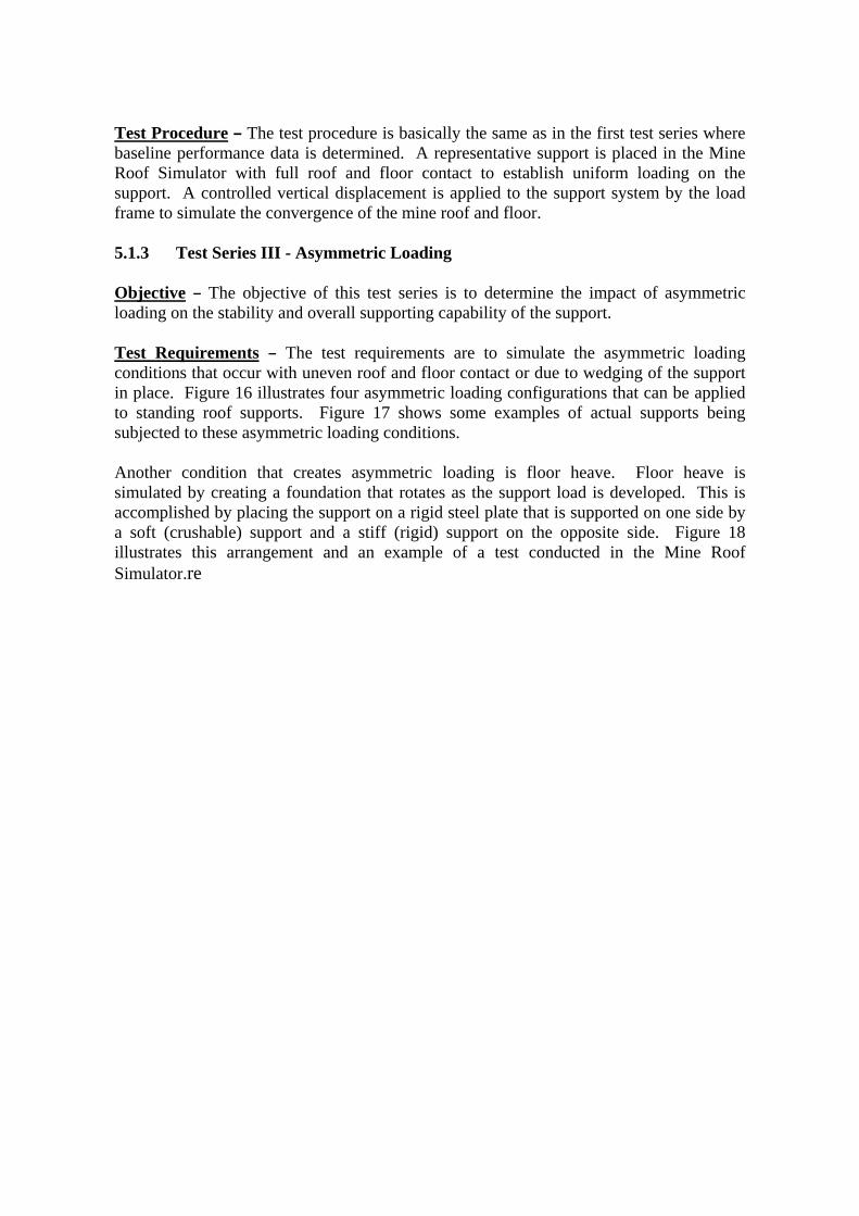
Test Procedure B The test procedure is basically the same as in the first test series where baseline performance data is determined. A representative support is placed in the Mine Roof Simulator with full roof and floor contact to establish uniform loading on the support. A controlled vertical displacement is applied to the support system by the load frame to simulate the convergence of the mine roof and floor. 5.1.3 Test Series III - Asymmetric Loading Objective B The objective of this test series is to determine the impact of asymmetric loading on the stability and overall supporting capability of the support. Test Requirements B The test requirements are to simulate the asymmetric loading conditions that occur with uneven roof and floor contact or due to wedging of the support in place. Figure 16 illustrates four asymmetric loading configurations that can be applied to standing roof supports. Figure 17 shows some examples of actual supports being subjected to these asymmetric loading conditions.
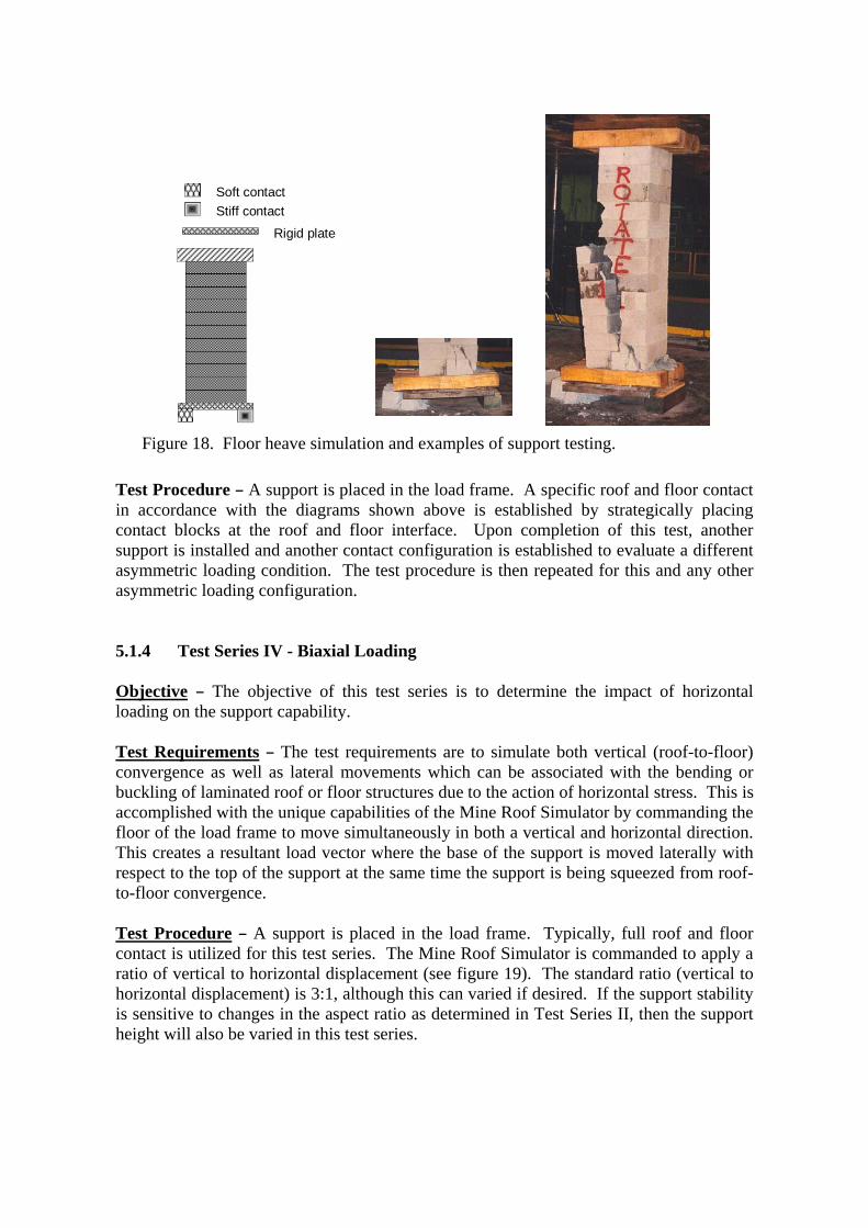
Another condition that creates asymmetric loading is floor heave. Floor heave is simulated by creating a foundation that rotates as the support load is developed. This is accomplished by placing the support on a rigid steel plate that is supported on one side by a soft (crushable) support and a stiff (rigid) support on the opposite side. Figure 18 illustrates this arrangement and an example of a test conducted in the Mine Roof Simulator.re
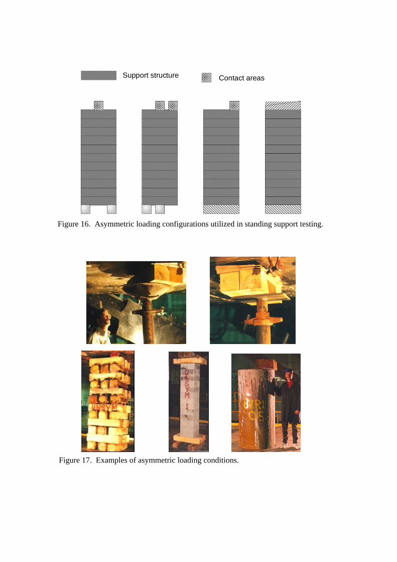
Figure 16. Asymmetric loading configurations utilized in standing support testing.
Contact areas Support structure
Figure 17. Examples of asymmetric loading conditions.
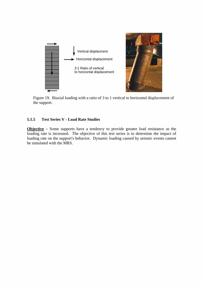
Test Procedure B A support is placed in the load frame. A specific roof and floor contact in accordance with the diagrams shown above is established by strategically placing contact blocks at the roof and floor interface. Upon completion of this test, another support is installed and another contact configuration is established to evaluate a different asymmetric loading condition. The test procedure is then repeated for this and any other asymmetric loading configuration. 5.1.4 Test Series IV - Biaxial Loading Objective B The objective of this test series is to determine the impact of horizontal loading on the support capability. Test Requirements B The test requirements are to simulate both vertical (roof-to-floor) convergence as well as lateral movements which can be associated with the bending or buckling of laminated roof or floor structures due to the action of horizontal stress. This is accomplished with the unique capabilities of the Mine Roof Simulator by commanding the floor of the load frame to move simultaneously in both a vertical and horizontal direction. This creates a resultant load vector where the base of the support is moved laterally with respect to the top of the support at the same time the support is being squeezed from roof-to-floor convergence. Test Procedure B A support is placed in the load frame. Typically, full roof and floor contact is utilized for this test series. The Mine Roof Simulator is commanded to apply a ratio of vertical to horizontal displacement (see figure 19). The standard ratio (vertical to horizontal displacement) is 3:1, although this can varied if desired. If the support stability is sensitive to changes in the aspect ratio as determined in Test Series II, then the support height will also be varied in this test series.
Figure 18. Floor heave simulation and examples of support testing.
Stiff contact Rigid plate
Soft contact
5.1.5 Test Series V - Load Rate Studies Objective B Some supports have a tendency to provide greater load resistance as the loading rate is increased. The objective of this test series is to determine the impact of loading rate on the support=s behavior. Dynamic loading caused by seismic events cannot be simulated with the MRS.
Figure 19. Biaxial loading with a ratio of 3 to 1 vertical to horizontal displacement of the support.
3:1 Ratio of verticalto horizontal displacement
Vertical displacment
Horizontal displacement
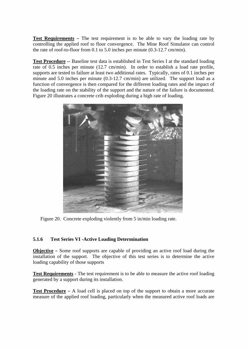
Test Requirements B The test requirement is to be able to vary the loading rate by controlling the applied roof to floor convergence. The Mine Roof Simulator can control the rate of roof-to-floor from 0.1 to 5.0 inches per minute (0.3-12.7 cm/min). Test Procedure -- Baseline test data is established in Test Series I at the standard loading rate of 0.5 inches per minute (12.7 cm/min). In order to establish a load rate profile, supports are tested to failure at least two additional rates. Typically, rates of 0.1 inches per minute and 5.0 inches per minute (0.3-12.7 cm/min) are utilized. The support load as a function of convergence is then compared for the different loading rates and the impact of the loading rate on the stability of the support and the nature of the failure is documented. Figure 20 illustrates a concrete crib exploding during a high rate of loading.
5.1.6 Test Series VI -Active Loading Determination Objective B Some roof supports are capable of providing an active roof load during the installation of the support. The objective of this test series is to determine the active loading capability of those supports Test Requirements - The test requirement is to be able to measure the active roof loading generated by a support during its installation. Test Procedure B A load cell is placed on top of the support to obtain a more accurate measure of the applied roof loading, particularly when the measured active roof loads are
Figure 20. Concrete exploding violently from 5 in/min loading rate.
expected to be less than 20 tons (18 metric tons). The load frame platens are commanded to remain stationary during the active load measurement. An effort is also made to determine whether the active loading remains constant or sheds with time once the support is installed. Hence, a plot of active roof load as a function of time is made and a decay rate is determined. The amount of time that the active roof loading is measured can depend of the type of support, but it is initially examined over a period of 30 minutes. 5.1.7 Test Series VII - Static Loading Evaluations Objective -- Static loads are used to assess creep and relaxation in the support material constructions. The objective of this test series is to determine the creep and relaxation properties of a support. Test Requirements -- Creep is the continuation of deformation after a static load is applied. To measure creep, a constant force must be applied to the support. Relaxation is the opposite of creep. Relaxation is the reduction in stress or load after an applied displacement. Hence, the test requirement to measure creep is to be able to maintain a constant displacement. Test Procedure B For the creep study, a support is placed in the load frame. The load frame is operated in force-control and a load is applied and held constant for an extended period. The change in displacement is then measured to determine the rate of creep. For the relaxation study, the load frame is operated in displacement control, and the support is loaded through a designated convergence, which is then held constant by the load frame. The change in support loading is then measured as a function of time to determine the relaxation properties of the support. 6.1 NIOSH SUPPORT TECHNOLOGY OPTIMIZATION PROGRAM (STOP) STOP is a window=s based software program that provides mine operators with a simple and practical tool to make engineering decisions regarding the selection and placement strategy of these various standing roof support technologies (Barczak, 2000). This program includes a complete data base of the support characteristics and loading profiles obtained through safety performance testing of these supports at the NIOSH Safety Structures Testing Laboratory. Support design criteria in the form of the required support load density at a specified convergence can be established from four options: (1) a data base of measured ground reaction data from various mines or ground behavior information inputted by the user, (2) determination of loading requirements based on a detached roof block or rock failure height, or (3) criteria based on the current roof support system, and (4) arbitrary criteria set the by user. Using these design criteria, the program will determine the installation requirements for a particular support technology that will provide the necessary support load density and convergence control. Optimization routines are also available to determine the most efficient support design for a user specified support installation.
Comparisons among the various support technologies are easily made including graphical analysis of relevant support parameters. STOP can provide an engineering foundation to ensure that inadequate support designs as well as ultra conservative support applications are avoided. Safety will be improved by proper matching of the support performance to the mine conditions, which will reduce the likelihood of roof falls and blocked escapeways. Material handling injuries associated with support construction are known to account for about 5,000 lost workdays per year in underground coal mines. STOP can help to define the material handling advantages of alternative support technologies that use lighter weight materials or systems that can be installed with the aid of mechanical assist. The use of these support technologies can significantly reduce material handling injuries. In addition to these performance and material handling measures, STOP can be used to compare support installation costs. 6.1.1 Program Architecture
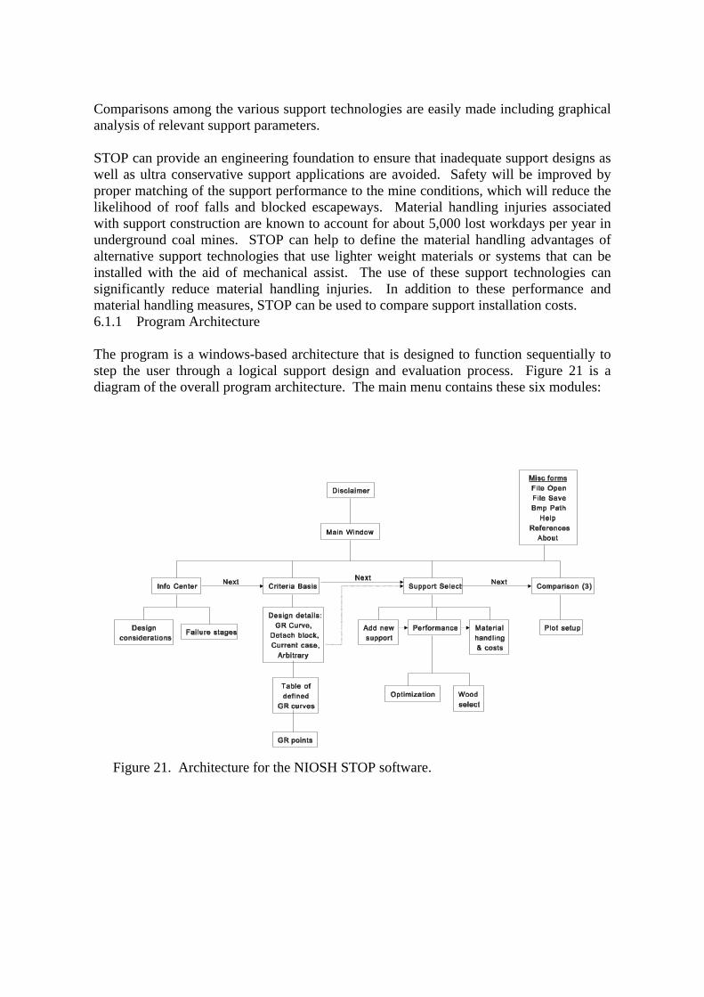
The program is a windows-based architecture that is designed to function sequentially to step the user through a logical support design and evaluation process. Figure 21 is a diagram of the overall program architecture. The main menu contains these six modules:
Figure 21. Architecture for the NIOSH STOP software.
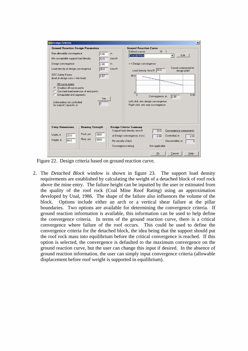
File B The File window contains file management subroutines that allows the user to create new files, open and close existing files, and exit from the program. The File Menu also allows the user to set the path for storage of several photographs that are incorporated into the program for visual display of the support performance. Information B The Information window can be thought of as a general information center. The various support technologies are categorized in seven groups: (1) conventional wood (crib) supports, (2) engineered timber supports, (3) conventional concrete crib supports, (4) yieldable concrete supports, (5) steel supports, (6) additional supports and (7) intrinsic supports. From this list and the embedded sub menus, the user can select a specific support and learn more about the support through several other program buttons. Keypoints provides a description of the support, design and installation considerations, and performance characteristics of the support. Performance displays the loading profile of the support with photographs that depict the deformation and associated support loading. NIOSH Testing Laboratory describes the Mine Roof Simulator and refers to the safety performance testing protocols through which the performance characteristics of the support were determined. Reference/Bibliography contains relevant reference material pertaining to the selected support system. Design Criteria B The Design Criteria window is where the load and convergence design criteria for the support system are formulated. The requirement is to define the required support load density in terms of tons of support capacity per lineal foot of entry advance and at what convergence this support capability is to be provided. The convergence is separated into two components: (1) controlled and (2) uncontrolled convergence. There are four different ways to establish these design criteria in the program: (1) detached block, (2) ground reaction curve, (3) current support system, and (4) arbitrary criteria. 1. The Ground Reaction Curve (figure 22) allows the user to define the support load
density and convergence criteria from in mine measurements of the ground behavior (convergence) associated with various support systems (Mucho, 1999). Essentially, the ground reaction concept measures the support and strata interaction and determines the convergence in the mine entry that is controlled by the magnitude of the support resistance. Generally, the convergence decreases with increasing support load density. Hence, if measurements of convergence are made with two or more support systems of varying stiffness, then a ground reaction curve can be established for that particular mine. The user can define a ground reaction curve or use one from the data base established from various mine sites which is maintained in the program. Once a ground reaction curve is defined, the program will determine the required spacing for a particular support system that will provide the support load density consistent with the ground reaction curve at a particular convergence.
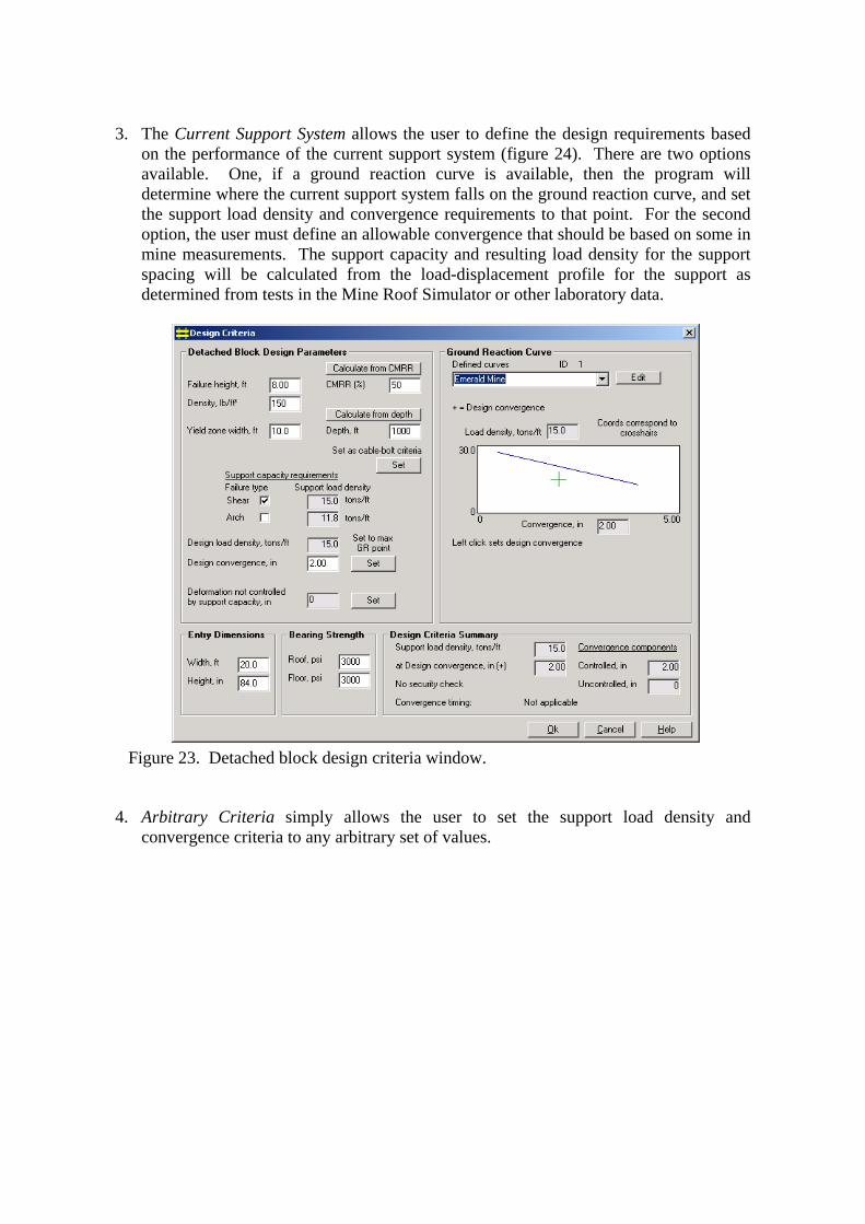
2. The Detached Block window is shown in figure 23. The support load density
requirements are established by calculating the weight of a detached block of roof rock above the mine entry. The failure height can be inputted by the user or estimated from the quality of the roof rock (Coal Mine Roof Rating) using an approximation developed by Unal, 1986. The shape of the failure also influences the volume of the block. Options include either an arch or a vertical shear failure at the pillar boundaries. Two options are available for determining the convergence criteria. If ground reaction information is available, this information can be used to help define the convergence criteria. In terms of the ground reaction curve, there is a critical convergence where failure of the roof occurs. This could be used to define the convergence criteria for the detached block, the idea being that the support should put the roof rock mass into equilibrium before the critical convergence is reached. If this option is selected, the convergence is defaulted to the maximum convergence on the ground reaction curve, but the user can change this input if desired. In the absence of ground reaction information, the user can simply input convergence criteria (allowable displacement before roof weight is supported in equilibrium).
Figure 22. Design criteria based on ground reaction curve.
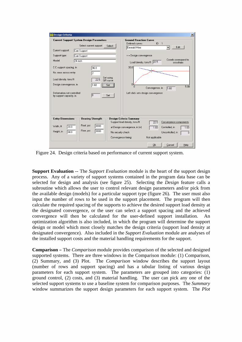
3. The Current Support System allows the user to define the design requirements based on the performance of the current support system (figure 24). There are two options available. One, if a ground reaction curve is available, then the program will determine where the current support system falls on the ground reaction curve, and set the support load density and convergence requirements to that point. For the second option, the user must define an allowable convergence that should be based on some in mine measurements. The support capacity and resulting load density for the support spacing will be calculated from the load-displacement profile for the support as determined from tests in the Mine Roof Simulator or other laboratory data.
4. Arbitrary Criteria simply allows the user to set the support load density and
convergence criteria to any arbitrary set of values.
Figure 23. Detached block design criteria window.
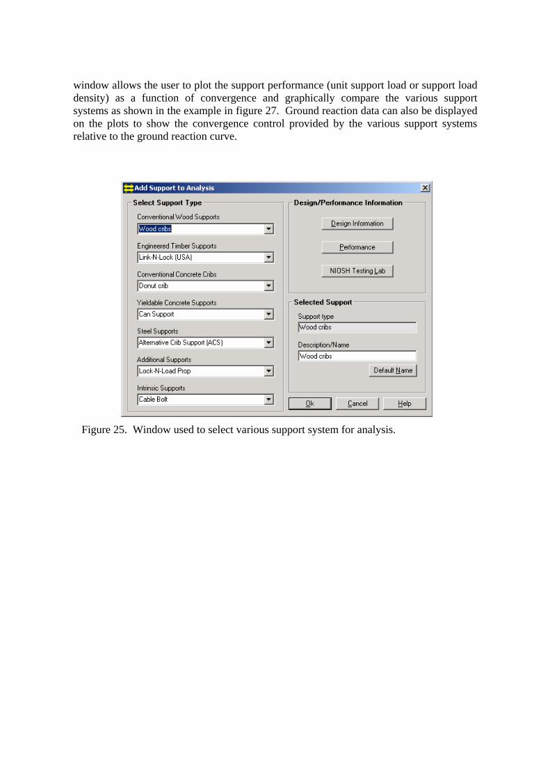
Support Evaluation -- The Support Evaluation module is the heart of the support design process. Any of a variety of support systems contained in the program data base can be selected for design and analysis (see figure 25). Selecting the Design feature calls a subroutine which allows the user to control relevant design parameters and/or pick from the available design (models) for a particular support type (figure 26). The user must also input the number of rows to be used in the support placement. The program will then calculate the required spacing of the supports to achieve the desired support load density at the designated convergence, or the user can select a support spacing and the achieved convergence will then be calculated for the user-defined support installation. An optimization algorithm is also included, in which the program will determine the support design or model which most closely matches the design criteria (support load density at designated convergence). Also included in the Support Evaluation module are analyses of the installed support costs and the material handling requirements for the support. Comparison B The Comparison module provides comparison of the selected and designed supported systems. There are three windows in the Comparison module: (1) Comparison, (2) Summary, and (3) Plot. The Comparison window describes the support layout (number of rows and support spacing) and has a tabular listing of various design parameters for each support system. The parameters are grouped into categories: (1) ground control, (2) costs, and (3) material handling. The user can pick any one of the selected support systems to use a baseline system for comparison purposes. The Summary window summarizes the support design parameters for each support system. The Plot
Figure 24. Design criteria based on performance of current support system.
window allows the user to plot the support performance (unit support load or support load density) as a function of convergence and graphically compare the various support systems as shown in the example in figure 27. Ground reaction data can also be displayed on the plots to show the convergence control provided by the various support systems relative to the ground reaction curve.
Figure 25. Window used to select various support system for analysis.
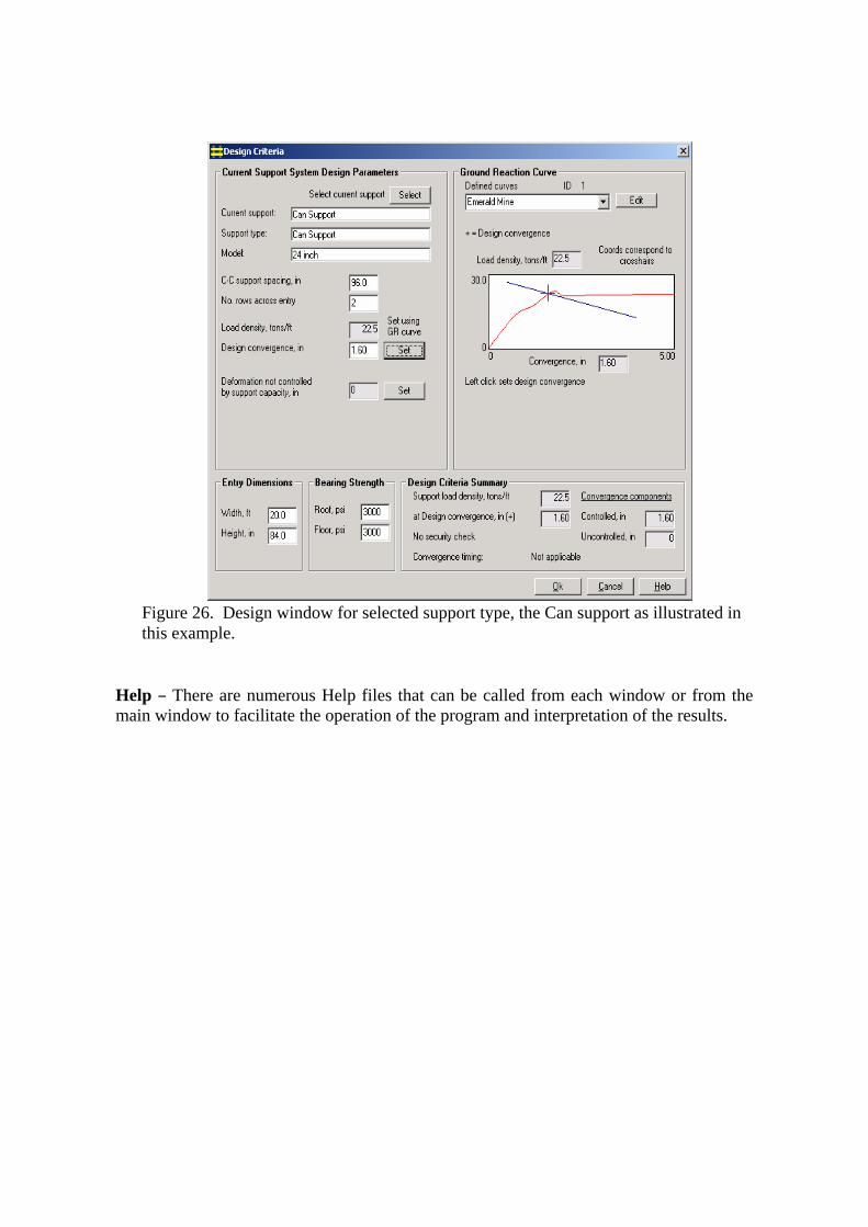
Help B There are numerous Help files that can be called from each window or from the main window to facilitate the operation of the program and interpretation of the results.
Figure 26. Design window for selected support type, the Can support as illustrated in this example.
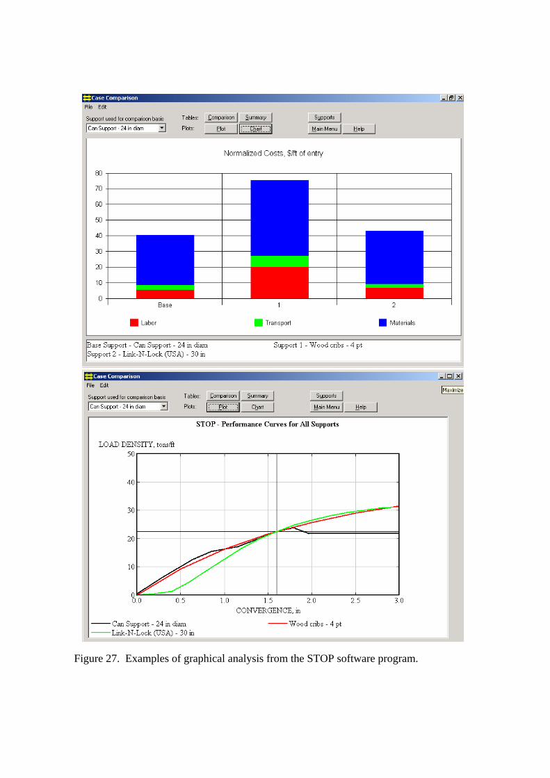
Figure 27. Examples of graphical analysis from the STOP software program.
7.1 SUMMARY Standing supports in the form of timber posts and wood cribs have been used since the very earliest days of underground mining and remained the most common form of support in U.S. coal mines until new support products were developed in the early 1990’s. Since then, dramatic improvements in roof support capability have been provided through generations of new support products, many of which have been adopted from the South Africa hard rock industry. Design features, such as prestressing, that are common in the hard rock industry, are relatively new to coal mining applications in the United States and much of this new technology is still being evaluated. NIOSH continues to play a vital role in the development of innovative roof support technologies for U.S. mines. A strong partnership has been developed with various roof support manufacturers and MSHA, through which full-scale testing of the support products are conducted at the NIOSH Mine Roof Simulator facility. A rigorous testing protocol has been developed that simulates the in-service loading conditions in underground mines. The testing is done on a volunteer basis, and provides the MSHA and mine operators with confidence in understanding the capabilities of the various support products prior to use in the mines. MSHA approves each support on a case-by-case basis and relies heavily on this information for the approval of new support technologies. As such, this work addresses the NIOSH mission statement of promoting the health and safety of the mine workers by providing them with effective roof support products. NIOSH also developed the STOP software program to facilitate the transfer of this technology and to provide a design basis upon which support systems can be applied in various mining applications. The program has been widely distributed and has become a standard for the design and evaluation of intrinsic cable and standing roof support systems. 8.1 REFERENCES 1. U.S. Mine Safety and Health Administration (Dept. Labor) [2004]. Mine Injuries
and Work Time, Quarterly: January-December 2004, Preliminiary, 33 p. 2. Barczak TM [2000]. Optimizing secondary roof support with the NIOSH Support
Technology Optimization Program (STOP). In: Proceedings of 19th International Conference on Ground Control in Mining, pp. 74-84.
3. Barczak T.M., Tadolini S.C., McKelvey P. [2004]. Hydraulic Prestressing Units: An Innovation in Roof Support Technology In: Proceedings of 23rd International Conference on Ground Control in Mining, pp. 286-294.
4. Barczak TM [2000]. NIOSH safety performance testing protocols for standing roof supports and longwall shields. US Department of Health and Human Services, Public Health Service, Center for Disease Control and Prevention, National Institute for Occupational Safety and Health, IC 9453, pp. 207-223.
5. Mucho TP, Barczak TM, Dolinar D, Bower J, Bryja J [1999]. Design methodology
for standing longwall tailgate support. In: Proceedings of 18th International Conference on Ground Control in Mining, pp. 136-149.
6. Unal E [1986]. Empirical Approach to Calculate Rock Loads in Coal Mine Roadways. In: Proceedings of 5th International Conference on Ground Control in Mining, pp. 234-241.