Embed Size (px)
Citation preview

Ar
TFTa
b
c
d
e
f
g
1
EtutmbtMisef
0d
chemical engineering research and design 8 7 ( 2 0 0 9 ) 1003–1016
Contents lists available at ScienceDirect
Chemical Engineering Research and Design
journa l homepage: www.e lsev ier .com/ locate /cherd
n overview on oxyfuel coal combustion—State of the artesearch and technology development
erry Walla,∗, Yinghui Liua, Chris Sperob, Liza Elliotta, Sameer Kharea, Renu Rathnama,arida Zeenathala, Behdad Moghtaderia, Bart Buhred, Changdong Shenge, Raj Guptaf,oshihiko Yamadac, Keiji Makinoc, Jianglong Yua,g
CRC for Coal in Sustainable Development (CCSD), University of Newcastle, NSW 2308, AustraliaCCSD, CS Energy, AustraliaIHI, JapanShell Development (Australia) Pty Ltd., AustraliaSchool of Energy and Environment, Southeast University, ChinaDepartment of Chemical and Materials Engineering, University of Alberta, CanadaShenyang Institute of Aeronautical Engineering and University of Science and Technology, Liaoning, China
a b s t r a c t
Oxyfuel combustion is seen as one of the major options for CO2 capture for future clean coal technologies. The paper
provides an overview on research activities and technology development through a fundamental research under-
pinning the Australia/Japan Oxyfuel Feasibility Project. Studies on oxyfuel combustion on a pilot-scale furnace and
a laboratory scale drop tube furnace are presented and compared with computational fluid dynamics (CFD) predic-
tions. The research has made several contributions to current knowledge, including; comprehensive assessment on
oxyfuel combustion in a pilot-scale oxyfuel furnace, modifying the design criterion for an oxy retrofit by matching
heat transfer, a new 4-grey gas model which accurately predicts emissivity of the gases in oxy-fired furnaces has
been developed for furnace modelling, the first measurements of coal reactivity comparisons in air and oxyfuel at
laboratory and pilot-scale; and predictions of observed delays in flame ignition in oxy-firing.
© 2009 The Institution of Chemical Engineers. Published by Elsevier B.V. All rights reserved.
Keywords: Oxyfuel coal combustion; CO2 capture; Heat transfer; CFD prediction; Reactivity
� Pre-combustion capture: Integrated gasification combined
. Introduction
nergy production from fossil fuel combustion results inhe emission of greenhouse gases, the dominant contrib-tor being CO2. Public awareness and legislation have ledo a policy of reduction of greenhouse gas emissions in
ost well-developed countries, with the regulations driveny international initiatives such as the Kyoto protocol andhe Intergovernmental Panel on Climate Change (IPCC, 2007).any talks have recently been held on post-Kyoto CO2 trad-
ng schemes. Apart from increasing usage of renewable energyources and nuclear power, the rapidly increasing global
nergy demand is expected to be met by conventional fossiluels. Reduction of greenhouse gas emission from fossil fuel-∗ Corresponding author. Tel.: +61 2 49 216179; fax: +61 2 49 216920.E-mail address: [email protected] (T. Wall).Received 21 August 2008; Received in revised form 25 November 2008
263-8762/$ – see front matter © 2009 The Institution of Chemical Engioi:10.1016/j.cherd.2009.02.005
fired power generation can be achieved by efficiency improve-ment, switching to lower carbon fuels and CO2 capture andstorage (CCS) (Wall, 2005). A recent report released by MIT indi-cates CO2 capture and storage is necessary for the future useof coal when carbon costs are established (Katzer, 2007).
There are several options for capture and storage of CO2
from coal combustion and gasification, including:
� Post-combustion capture: CO2 capture from conventional pul-verised coal-firing plant with scrubbing of the flue gas bychemical solvents, solid minerals etc.
; Accepted 16 February 2009
cycle (IGCC) with a shift reactor to convert CO to CO2, fol-lowed by CO2 capture.
neers. Published by Elsevier B.V. All rights reserved.

1004 chemical engineering research and d
Nomenclature
AFT adiabatic flame temperatureCFD computational fluid dynamicDTF drop tube furnaceFEGT furnace exit gas temperatureIFRF International Flame Research FoundationTGA thermogravimetric analysisType-0 and type 2-flames identified by the IFRF, these
are for forward flowing jet flames and flameswith international recirculation respectively
WSGGM weighted sum of gray gases modelWSM well-stirred model, a simple mass and heat bal-
ance for a furnace
� Typically, when air-firing coal, 20% excess air is used. Oxy-
� Oxyfuel combustion: Combustion in oxygen rather than air,with recycled flue gas.
� Chemical looping combustion: Oxygen carried by solid oxygencarriers reacts with fuel to produce a high concentrationCO2 stream in the flue gas, oxygen carriers are then regen-erated to uptake oxygen from air in a second reactor.
This review is focused on the science underpinning oxyfuelcombustion technology.
Conventional pf coal-fired boilers, i.e., currently being usedin power industry, use air for combustion in which the nitro-gen from the air (approximately 79% by volume) dilutes theCO2 concentration in the flue gas. During oxyfuel combustion,a combination of oxygen (typically of greater than 95% purity)and recycled flue gas is used for combustion of the fuel. A gasconsisting mainly of CO2 and water is generated with a con-centration of CO2 ready for sequestration. The recycled fluegas is used to control flame temperature and make up the vol-ume of the missing N2 to ensure there is enough gas to carrythe heat through the boiler. A general flow sheet is shownin Fig. 1. CO2 capture and storage by the current technicallyviable options post-combustion capture, pre-combustion cap-ture and oxyfuel combustion will impose a 7–10% efficiencypenalty on the power generation process. The major contrib-utors to this efficiency penalty are oxygen production and CO2
compression.The concept of oxyfuel combustion was proposed in 1982
by Abraham in the context of providing a CO2-rich flue gasfor enhanced oil recovery (Abraham et al., 1982). Due to thesepotential benefits, Argonne National Laboratory (ANL) car-ried out some research activities including a techno-economicstudy and pilot-scale studies (Weller et al., 1985; Berry andWolsky, 1986; Wang et al., 1988; Abele et al., 1987). During theearly 1990s, because of interest in capturing CO2 from coalcombustion, IFRF performed the first oxy-coal combustionwith RFG (recirculated flue gas) in a pilot-scale study in Europe,NEDO initiated a study on oxy-coal combustion with RFG, toallow consideration of retrofitting Japanese boilers with thetechnology. Combustion trials were completed by IHI (Nozakiet al., 1997; Kiga et al., 1997; Kimura et al., 1995; Nakayamaet al., 1992). During the late 1990s, CANMET and a researchconsortium led by Babcock and Wilcox and Air Liquide didfurther pilot-scale studies. Based on these developments, oxy-fuel technology has now evolved from pilot-scale to severalplanned demonstration scale projects.
The literature contains many reviews of the developmentof the technology (Wall, 2005; Santos et al., 2006; Croiset et al.,
esign 8 7 ( 2 0 0 9 ) 1003–1016
2005; White et al., 2003; Kiga, 2001; Allam et al., 2005; Buhre etal., 2005). Thus this review is scoped on original R&D researchactivities on a fundamental level carried out at the Universityof Newcastle under the framework of a joint Australia–JapanCallide A Oxyfuel feasibility study, updating the state-of-the-art oxyfuel technology reviewed in 2005 (Buhre et al., 2005) and2007 (T.F. Wall, 2007) respectively. The most important consid-eration of the paper is the understanding of the differencesbetween oxyfuel combustion and conventional combustion,including heat transfer, coal reactivity and emissions. The cur-rent paper presents research in these areas, which has mostrelevance to a boiler retrofit. Compared with the other tworeviews published from this group, the current review empha-sis is scientific understanding of the oxyfuel technology, ratherthan the previous technical point of view. Research conductedwithin the scope of the current paper has primarily been pre-sented at international conferences and published as journalpapers (Wall, 2005; T. Wall, 2007; T.F. Wall, 2007; Rathnam et al.,2006, 2007; S.P. Khare et al., 2007; Khare et al., 2008; Yamada etal., 2006; Lundstöm et al., 2006; Gupta et al., 2006; Spero, 2007).
2. Differences between air and oxyfuelcombustion conditions
From pilot-scale and laboratory scale experimental studies,oxyfuel combustion has been found to differ from air com-bustion in several ways, including reduced flame temperature,delayed flame ignition, reduced NOx and SOx emissions.
Many of these effects can be explained by differences ingas properties between CO2 and N2, the main diluting gasesin oxyfuel and air respectively. CO2 has different propertiesfrom N2 which influence both heat transfer and combustionreaction kinetics:
� Density: The molecular weight of CO2 is 44, compared to 28for N2, thus the density of the flue gas is higher in oxyfuelcombustion.
� Heat capacity: The heat capacity of CO2 is higher than N2.� Diffusivity: The oxygen diffusion rate in CO2 is 0.8 times that
in N2.� Radiative properties of the furnace gases: Oxyfuel combustion
has higher CO2 and H2O levels, both having high emittingpower.
The following list identifies differences for oxy-firing com-pared to air-firing:
� To attain a similar adiabatic flame temperature (AFT) theO2 proportion of the gases passing through the burners ishigher, typically 30%, than that for air (of 21%), necessitat-ing that about 60% of the flue gas is recycled.
� The high proportions of CO2 and H2O in the furnace gasesresult in higher gas emissivities, so that similar radia-tive heat transfer for a boiler retrofitted to oxyfuel willbe attained when the O2 proportion of the gases passingthrough the burner is less than the 30% required for thesame AFT.
� The volume of gases flowing through the furnace is reducedby which the extent is dependent on the flue gas recycleratio, and the volume of flue gas emitted from power plantis reduced by about 80%.
fuel requires a percent excess O2 (defined as the O2 suppliedin excess of that required for stoichiometric combustion of
chemical engineering research and design 8 7 ( 2 0 0 9 ) 1003–1016 1005
F n wio
�
�
3
3
Ase1f
ig. 1 – Flowsheet of oxyfuel technology for power generatioperations in bold.
the coal supply) to achieve a similar O2 fraction in the fluegas as air-firing, in the range of 3–5%.Due to the recycling of flue gases to the furnace, species(including corrosive sulphur gases) have higher concentra-tions than in air-firing, if these species are not removedprior to recycle.As oxyfuel combustion combined with sequestration mustprovide power to several significant unit operations, suchas flue gas compression, that are not required in aconventional plant without sequestration, oxyfuel com-bustion/sequestration is less efficient per unit of energyproduced.
. Pilot-scale furnace experiments
.1. Furnace and experimental details
simulation of the oxyfuel process requires a recycled gastream of multiple species and multiple concentration lev-
ls, which is difficult to achieve at laboratory scale. Thus the50 kg/h IHI combustion test facilities in Aioi, Japan was there-ore used to test three Australian pulverised coals under bothTable 1 – Analysis of coals used in pilot-scale tests.
Coal AHHV = 23.7 dry MJ/kg
Proximate analysisI.M. [a.d.%] 8.8Ash [dry%] 19.3V.M. [dry%] 25.7F.C. [dry%] 55.0
Ultimate analysisC [dry%] 63.5H [dry%] 2.8N [dry%] 0.73O [dry%] 13.5S [dry%] 0.24
Ash analysisSiO2 [wt%] 47.6Al2O3 [wt%] 28.6Fe2O3 [wt%] 16.0CaO [wt%] 1.64MgO [wt%] 1.12TiO2 [wt%] 2.22
th CO2 capture and storage, showing the additional unit
oxyfuel and air combustion conditions. In such a furnace fluegas recycling is well simulated. The purpose of these tests wasto obtain design data on flame stability, combustion charac-teristics, gaseous emissions, fly ash characteristics, and plantoperation including turndown, and to provide data for fun-damental interpretation and mathematical modelling. Here,differences and trends are identified and the data will be inter-preted in the latter sections in a greater detail.
A direct comparison of oxyfuel and air combustion wasmade, with coals fired at the same throughput, same flue O2
concentration, and the same average O2 through the burn-ers. The average O2 through the burners was 27% (wet), in anattempt to establish the same heat transfer. A lower adiabaticflame temperature (AFT) for the oxyfuel conditions result.
Three coals were tested in the pilot-scale furnace in Aioi,with properties given in Table 1. The laboratory experimentswere undertaken on size cuts of the same coals, with proper-ties given in Table 2.
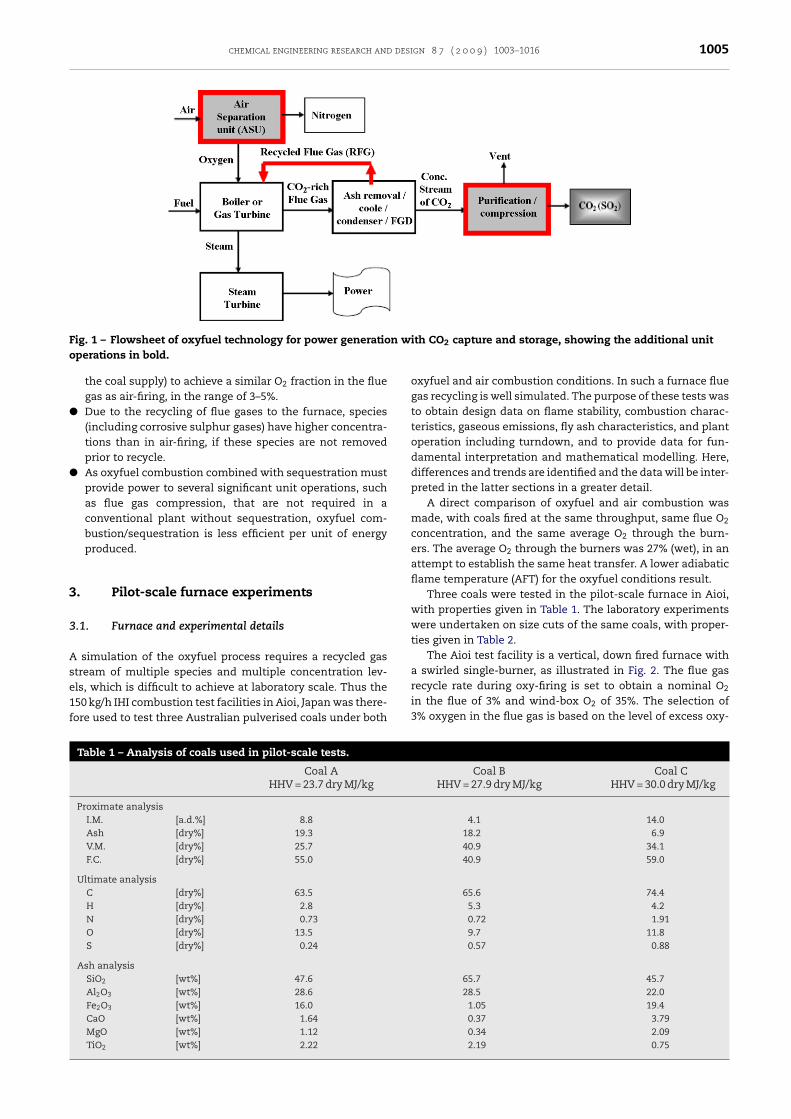
The Aioi test facility is a vertical, down fired furnace witha swirled single-burner, as illustrated in Fig. 2. The flue gas
recycle rate during oxy-firing is set to obtain a nominal O2in the flue of 3% and wind-box O2 of 35%. The selection of3% oxygen in the flue gas is based on the level of excess oxy-
Coal B Coal CHHV = 27.9 dry MJ/kg HHV = 30.0 dry MJ/kg
4.1 14.018.2 6.940.9 34.140.9 59.0
65.6 74.45.3 4.20.72 1.919.7 11.80.57 0.88
65.7 45.728.5 22.0
1.05 19.40.37 3.790.34 2.092.19 0.75
1006 chemical engineering research and design 8 7 ( 2 0 0 9 ) 1003–1016
Table 2 – Proximate and ultimate analysis of the size cuts of the Coals A, B and C used in laboratory experiments.
Coal A (+63–90 �m) Coal B (+63–90 �m) Coal C (+63–90 �m)
Proximate analysis wt% (air dried basis)Air-dried moisture 8.0 1.7 5.9Ash (a.d.) 19.9 19.6 5.0Volatile matter (a.d.) 25.6 40.5 33.8Fixed carbon (a.d.) 46.5 38.2 55.3
Ultimate analysis wt% (dry ash free basis)Carbon 79.1 81.6 78.4Hydrogen 4.51 6.84 5.13Nitrogen 1.16 1.26 2.14Sulphur 0.24 0.64 0.52Oxygen 15.0 9.7 13.8
Fig. 2 – Schematic of the IHI combustion test facility, indicating the unit-operations and sampling positions of deposits inns.
the furnace, and gas and solids in the post-furnace operatiogen commonly experienced in air combustion boilers in steampower plants. By fixing the oxygen concentration in the fluegas and then tuning the recycle ratio of the flue gas, the oxygenconcentration at the burner inlet can be adjusted. The result-ing stoichiometric ratio in oxyfuel is less than that used inair combustion. This established the average O2 through theburner at 27%, a condition predicted by theory where the fur-nace heat transfer is matched with the heat transfer duringair-firing. Mill conditions were set to achieve a nominal pul-verised coal fineness of 75% mass <75 �m. Other conditions
are given in Table 3, which indicates O2 levels and the threethermal inputs used to study turndown.Table 3 – Pilot-scale measurements, overall heat transfer predic
A
Air Ox
Well-stirred modelEstimated furnace heat transfer (kW) 348 35Estimated heat flux (kW/m2) 12.6 1% difference, change from air to oxy +1.6% +
Water-side heat balance Using water flow ∼Water inlet temperature (◦C) 37.8 3Water exit temperature (◦C) 47.5 4Estimated furnace heat absorption (kW) 354 39
3.2. Measurements
Flame temperatures were measured by a radiation thermome-ter corrected to the estimated gas emissivity. In the dimensionrange of the test furnace, gas emissivity increases from 0.45in air combustion to 0.55 in oxyfuel combustion. Details ofthe temperature measurement correction for gas emissivityare described elsewhere (Khare et al., 2008). Fig. 3 shows acomparison between air combustion and oxygen combustiontemperature profiles for Coal A after the oxyfuel flame tem-
perature was corrected. For all coals, the maximum flametemperature in air combustion was typically 100–150 ◦C highertion and measured by cooling water temperature rise.
Coal
B C
y Air Oxy Air Oxy
4 368 373 342 3472.8 13.3 13.5 12.3 12.51.5% +1.6%
25 T/h8.1 32.8 34.2 -NA -NA9.1 40.9 44.0 -NA -NA2 336 356 -NA -NA

chemical engineering research and design 8 7 ( 2 0 0 9 ) 1003–1016 1007
Fig. 3 – Gas temperature profiles measured by radiationpyrometry for Coal A.
Fig. 4 – Carbon-in-ash comparisons for oxy mode and airmode. The unbroken line shows the trend of lower carbonin ash during oxyfuel combustion and the broken liner
tt
csgf
(spCCcl
vatbi
4
Ftwfi
Fig. 5 – The O2 partial pressure (fraction) required at burnerinlet (to achieve similar adiabatic flame temperature as theair-fired case) for oxy-wet and oxy-dry (with 3.3% (v/v) O2
epresents parity.
han the oxyfuel flame temperature, and the furnace exit gasemperature (FEGT) was also higher in about 50 ◦C.
CO2 concentration at the heat exchanger inlet in oxyfuelombustion was 70–80 dry%. This low value is because of aubstantial air ingress from the devices such as the furnace,as cooler and heat exchanger due to operations at an in-urnace pressure of about −0.1 kPa.
Fig. 4 shows the analysis results of carbon-in-ash in fly ashdetermined by loss on ignition) collected using iso-kineticampling at the heat exchanger inlet. Oxyfuel combustionroduced a relatively lower carbon-in-ash for Coal A andoal B though the value of carbon-in-ash fluctuates in Coal, apparently due to operational fluctuations. Overall, thearbon-in-ash for oxyfuel combustion was approximately 40%ower than for air combustion.
Flame conditions during the combustion test were adjustedia a single air register around the burner with photographsnd a visual record used to identify differences in ignition loca-ion. The oxy-flames ignited at a greater distance from theurner. At low load operation, the oxy-flames were seen to
gnite at a substantially greater distance from the burner.
. Heat transfer
urnace heat transfer depends on flame temperature, heat
ransfer properties of gases and particulates, water coolingall temperature and properties, and the aerodynamic fluideld established, including the flame types.in the flue gas).
The adiabatic flame temperature (AFT) of coal combustionin high oxygen concentrations is extremely high due to thelack of N2 dilution. But the AFT of coal combustion in 21% oxy-gen with CO2 dilution is lower than air combustion becauseof the higher heat capacity of CO2. By adjusting the ratio ofrecycled flue gas and thereby the oxygen concentration atthe burner inlet, an adiabatic flame temperature similar toair combustion can be achieved; approximately 30% O2 at theburner inlet. For a retrofit, to minimize changes in the currentcombustion system requires selection of an oxygen concen-tration at the burner inlet by selecting a ratio of recycled fluegas, which will vary depending on if the flue gas is dried, toachieve similar heat transfer as air combustion. Fig. 5 com-pares the adiabatic flame temperature for air and oxy-retrofitcombustion where the AFT for air combustion is estimated for20% excess air and O2 levels in the flue gas at 3.3% (v/v). Thefeed condition for the combustion air includes primary flow(at 360 K) and secondary flow (560 K). The two oxy-retrofit com-bustion cases included in the figure are: oxy-wet recycle wherethe recycled flue gas includes water vapour, and oxy-dry recy-cle where water vapour is removed from the recycled flue gas.Under similar boundary conditions as air combustion, suchas the same coal feed rate and combustion gas temperatures,the computation results show that the % excess O2 requiredto maintain O2 levels in the flue gas similar to air combustionis in the range of 3–5% for both oxy-dry and oxy-wet combus-tion. Similar levels of adiabatic flame temperatures (comparedto air combustion) can then be established by changing the O2
levels at the burner inlet (after recycle) through adjustmentof the amount of recycled flue gas for oxy-wet and oxy-drycases. From Fig. 5, to achieve the same AFT as the air combus-tion included in the figure, the O2 fraction at the burner inletfor oxy-wet and oxy-dry combustion is approximately 28% or35% for wet and dry recycle respectively. Partial drying of therecycled gas will give AFTs between these values.
For a retrofit furnace, the heat transfer produced duringoxyfuel combustion must match the heat transfer during aircombustion. This constraint is due to the amount of steamrequired to drive the steam turbine. Radiation is the princi-pal mode of heat transfer in coal-fired furnaces. The maincombustion products that actively participate in radiative heattransfer are CO2, H2O and particulate matter such as char, sootand fly ash particles. The furnace gases in oxyfuel combustionhave much higher levels of CO2, H2O and a different CO2/H2O
ratio to air combustion, and, due to lower gas volumes, higherparticulate matter concentrations than air combustion. Thus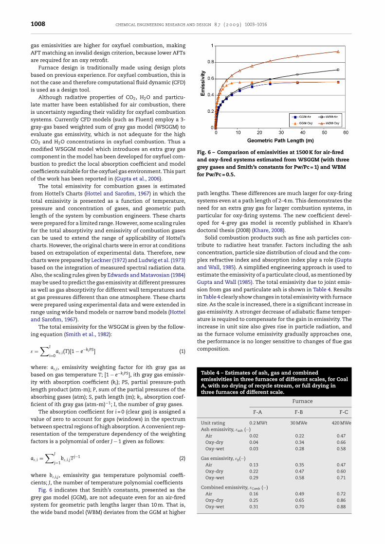
and design 8 7 ( 2 0 0 9 ) 1003–1016
Fig. 6 – Comparison of emissivities at 1500 K for air-firedand oxy-fired systems estimated from WSGGM (with threegrey gases and Smith’s constants for Pw/Pc = 1) and WBM
composition.
Table 4 – Estimates of ash, gas and combinedemissivities in three furnaces of different scales, for CoalA, with no drying of recycle stream, or full drying inthree furnaces of different scale.
Furnace
F-A F-B F-C
Unit rating 0.2 MWt 30 MWe 420 MWeAsh emissivity, εash (−)
Air 0.02 0.22 0.47Oxy-dry 0.04 0.34 0.66Oxy-wet 0.03 0.28 0.58
Gas emissivity, εg(−)Air 0.13 0.35 0.47Oxy-dry 0.22 0.47 0.60Oxy-wet 0.29 0.58 0.71
Combined emissivity, εComb (−)Air 0.16 0.49 0.72
1008 chemical engineering research
gas emissivities are higher for oxyfuel combustion, makingAFT matching an invalid design criterion, because lower AFTsare required for an oxy retrofit.
Furnace design is traditionally made using design plotsbased on previous experience. For oxyfuel combustion, this isnot the case and therefore computational fluid dynamic (CFD)is used as a design tool.
Although radiative properties of CO2, H2O and particu-late matter have been established for air combustion, thereis uncertainty regarding their validity for oxyfuel combustionsystems. Currently CFD models (such as Fluent) employ a 3-gray-gas based weighted sum of gray gas model (WSGGM) toevaluate gas emissivity, which is not adequate for the highCO2 and H2O concentrations in oxyfuel combustion. Thus amodified WSGGM model which introduces an extra gray gascomponent in the model has been developed for oxyfuel com-bustion to predict the local absorption coefficient and modelcoefficients suitable for the oxyfuel gas environment. This partof the work has been reported in (Gupta et al., 2006).
The total emissivity for combustion gases is estimatedfrom Hottel’s Charts (Hottel and Sarofim, 1967) in which thetotal emissivity is presented as a function of temperature,pressure and concentration of gases, and geometric pathlength of the system by combustion engineers. These chartswere prepared for a limited range. However, some scaling rulesfor the total absorptivity and emissivity of combustion gasescan be used to extend the range of applicability of Hottel’scharts. However, the original charts were in error at conditionsbased on extrapolation of experimental data. Therefore, newcharts were prepared by Leckner (1972) and Ludwig et al. (1973)based on the integration of measured spectral radiation data.Also, the scaling rules given by Edwards and Matavosian (1984)may be used to predict the gas emissivity at different pressuresas well as gas absorptivity for different wall temperatures andat gas pressures different than one atmosphere. These chartswere prepared using experimental data and were extended inrange using wide band models or narrow band models (Hotteland Sarofim, 1967).
The total emissivity for the WSGGM is given by the follow-ing equation (Smith et al., 1982):
ε =∑I
i=0aε,i(T)[1 − e−kiPS] (1)
where: aε,i, emissivity weighting factor for ith gray gas asbased on gas temperature T; [1 − e−kiPS], ith gray gas emissiv-ity with absorption coefficient (ki); PS, partial pressure-pathlength product (atm-m); P, sum of the partial pressures of theabsorbing gases (atm); S, path length (m); ki, absorption coef-ficient of ith gray gas (atm-m)−1; I, the number of gray gases.
The absorption coefficient for i = 0 (clear gas) is assigned avalue of zero to account for gaps (windows) in the spectrumbetween spectral regions of high absorption. A convenient rep-resentation of the temperature dependency of the weightingfactors is a polynomial of order J − 1 given as follows:
aε,i =∑J
j=1bε,i,jT
j−1 (2)
where bε,i,j, emissivity gas temperature polynomial coeffi-cients; J, the number of temperature polynomial coefficients
Fig. 6 indicates that Smith’s constants, presented as the
grey gas model (GGM), are not adequate even for an air-firedsystem for geometric path lengths larger than 10 m. That is,the wide band model (WBM) deviates from the GGM at higherfor Pw/Pc = 0.5.
path lengths. These differences are much larger for oxy-firingsystems even at a path length of 2–4 m. This demonstrates theneed for an extra gray gas for larger combustion systems, inparticular for oxy-firing systems. The new coefficient devel-oped for 4-grey gas model is recently published in Khare’sdoctoral thesis (2008) (Khare, 2008).
Solid combustion products such as fine ash particles con-tribute to radiative heat transfer. Factors including the ashconcentration, particle size distribution of cloud and the com-plex refractive index and absorption index play a role (Guptaand Wall, 1985). A simplified engineering approach is used toestimate the emissivity of a particulate cloud, as mentioned byGupta and Wall (1985). The total emissivity due to joint emis-sion from gas and particulate ash is shown in Table 4. Resultsin Table 4 clearly show changes in total emissivity with furnacesize. As the scale is increased, there is a significant increase ingas emissivity. A stronger decrease of adiabatic flame temper-ature is required to compensate for the gain in emissivity. Theincrease in unit size also gives rise in particle radiation, andas the furnace volume emissivity gradually approaches one,the performance is no longer sensitive to changes of flue gas
Oxy-dry 0.25 0.65 0.86Oxy-wet 0.31 0.70 0.88
chemical engineering research and design 8 7 ( 2 0 0 9 ) 1003–1016 1009
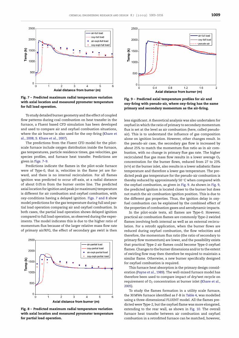
Fig. 7 – Predicted maximum radial temperature variationwf
flfawa
sgsg
wwioaiomtbcimo
Fwf
Fig. 9 – Predicted axial temperature profiles for air andoxy-firing with pseudo-air, where oxy-firing has the same
ith axial location and measured pyrometer temperatureor full load operation.
To study detailed burner geometry and the effect of coupledow patterns during coal combustion on heat transfer in the
urnace, a Fluent based CFD simulation has been developednd used to compare air and oxyfuel combustion situations,here the air burner is also used for the oxy-firing (Khare et
l., 2008; S. Khare et al., 2007).The predictions from the Fluent CFD model for the pilot-
cale furnace include oxygen distribution inside the furnace,as temperatures, particle residence times, gas velocities, gaspecies profiles, and furnace heat transfer. Predictions areiven in Figs. 7–9.
Predictions indicate the flames in the pilot-scale furnaceere of Type-0, that is, velocities in the flame jet are for-ard, and there is no internal recirculation. For all flames
gnition was predicted to occur off-axis, at a radial distancef about 0.05 m from the burner centre line. The predictedxial location for ignition and peak (or maximum) temperatures different for air combustion and oxyfuel combustion, withxy-conditions having a delayed ignition. Figs. 7 and 8 showodel predictions for the gas temperature during full and par-
ial load operation comparing air and oxyfuel combustion. Inoth cases, the partial load operation shows delayed ignitionompared to full load operation, as observed during the exper-
ments. The model indicates this is due to the higher ratio ofomentum flux because of the larger relative mass flow ratef primary air/RFG, the effect of secondary gas swirl is then
ig. 8 – Predicted maximum radial temperature variationith axial location and measured pyrometer temperature
or partial load operation.
primary and secondary momentum as the air-firing.
less significant. A theoretical analysis was also undertaken foroxyfuel in which the ratio of primary to secondary momentumflux is set at the level as air combustion (here, called pseudo-air). This is to understand the influence of gas compositionalone on ignition location. However, other changes result. Inthe pseudo-air case, the secondary gas flow is increased byabout 25% to match the momentum flux ratio as in air com-bustion, with no change in primary flue gas rate. The higherrecirculated flue gas mass flow results in a lower average O2
concentration for the burner flows, reduced from 27 to 23%(v/v) at the burner inlet, also results in a lower adiabatic flametemperature and therefore a lower gas temperature. The pre-dicted peak gas temperature for the pseudo-air combustion isthereby reduced by approximately 50 ◦C when compared withthe oxyfuel combustion, as given in Fig. 9. As shown in Fig. 9,the predicted ignition is located closer to the burner but doesnot match the air combustion ignition position. This is due tothe different gas properties. Thus, the ignition delay in oxy-fuel combustion can be explained by the combined effect ofthe properties of combustion gases and aerodynamic impacts.
In the pilot-scale tests, all flames are Type-0. However;practical air combustion flames are commonly Type-2 swirledflames involving both internal as well as an external recircu-lation. For a retrofit application, when the burner flows arereduced during oxyfuel combustion, the flow velocities andtherefore, the momentum flux ratio (the ratio of secondary toprimary flow momentum) are lower, and the possibility existsthat practical Type-2 air flames could become Type-0 oxyfuelflames. Changes to the burner dimensions and/or to the extentof swirling flow may then therefore be required to maintain asimilar flame. Otherwise, a new burner specifically designedfor oxyfuel combustion is required.
This furnace heat absorption is the primary design consid-eration (Payne et al., 1989). The well-mixed furnace model hastherefore been used to compare impact of dry/wet recycle onrequirement of O2 concentration at burner inlet (Khare et al.,2005).
To study the flames formation in a utility scale furnace,the 30 MWe furnace identified as F-B in Table 4, was modelledusing a three-dimensional FLUENT model. All the flames pre-dicted were Type-2, but the oxyfuel flame was more elongated,extending to the rear wall, as shown in Fig. 10. The overall
furnace heat transfer between air combustion and oxyfuelcombustion in a retrofitted furnace can be matched, however,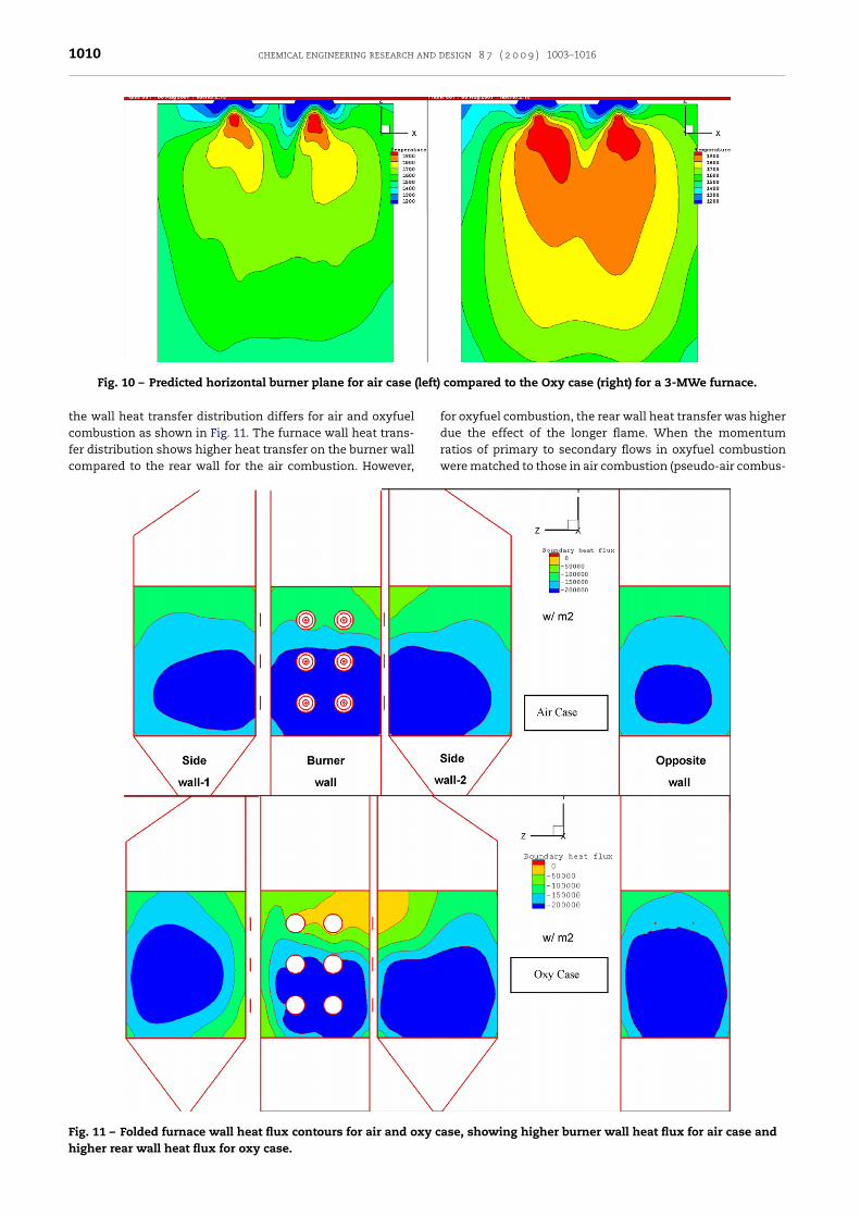
1010 chemical engineering research and design 8 7 ( 2 0 0 9 ) 1003–1016
(left)
Fig. 10 – Predicted horizontal burner plane for air casethe wall heat transfer distribution differs for air and oxyfuel
combustion as shown in Fig. 11. The furnace wall heat trans-fer distribution shows higher heat transfer on the burner wallcompared to the rear wall for the air combustion. However,Fig. 11 – Folded furnace wall heat flux contours for air and oxy chigher rear wall heat flux for oxy case.
compared to the Oxy case (right) for a 3-MWe furnace.
for oxyfuel combustion, the rear wall heat transfer was higher
due the effect of the longer flame. When the momentumratios of primary to secondary flows in oxyfuel combustionwere matched to those in air combustion (pseudo-air combus-ase, showing higher burner wall heat flux for air case and
chemical engineering research and design 8 7 ( 2 0 0 9 ) 1003–1016 1011
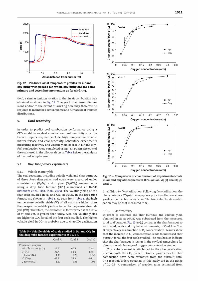
Fig. 12 – Predicted axial temperature profiles for air andoxy-firing with pseudo-air, where oxy-firing has the samep
tosrd
5
ICkmmfto
5
5Tosu(ffttyoav
Fig. 13 – Comparison of char burnout of experimental coalsin air and oxy atmospheres in DTF. (a) Coal A; (b) Coal B; (c)
rimary and secondary momentum as for air-firing.
ion), a similar ignition location to that in air combustion wasbtained as shown in Fig. 12. Changes to the burner dimen-ions and/or to the extent of swirling flow may therefore beequired to maintain a similar flame and furnace heat transferistributions.
. Coal reactivity
n order to predict coal combustion performance using aFD model in oxyfuel combustion, coal reactivity must benown. Inputs required include high temperature volatileatter release and char reactivity. Laboratory experimentseasuring reactivity and volatile yield of coal in air and oxy-
uel combustion were completed using +63–90 �m size cuts ofhe coals used in the pilot-scale tests. Table 2 gives the analysisf the coal samples used.
.1. Drop tube furnace experiments
.1.1. Volatile matter yieldhe coal reactions, including volatile yield and char burnout,f three Australian pulverised coals were measured underimulated air (O2/N2) and oxyfuel (O2/CO2) environmentssing a drop tube furnace (DTF) maintained at 1673 K
Rathnam et al., 2006, 2007, 2009). The volatile yields of theour coals studied in N2 and CO2 at 1673 K in the drop tubeurnace are shown in Table 5. As seen from Table 5, the highemperature volatile yields (V*) of all coals are higher thanheir respective volatile yields obtained by the proximate anal-sis (VM). Therefore, the estimated Q factor which is the ratiof V* and VM, is greater than unity. Also, the volatile yields
re higher in CO2 for all of the four coals studied. The higherolatile yield in CO2 is probably due to char-CO2 gasificationTable 5 – Volatile yields of coals studied in N2 and CO2 inthe drop tube furnace experiments at 1673 K.
Coal A Coal B Coal C
Proximate analysisVolatile matter (a.d.) 25.6 40.5 33.8V* (N2) 36.7 52.4 53.5Q factor (N2) 1.43 1.29 1.58V* (CO2) 43.3 55.3 66.2Q factor (CO2) 1.69 1.36 1.96
Coal C.
in addition to devolatilisation. Following devolatilisation, thechar contacts a CO2-rich atmosphere prior to collection wheregasification reactions can occur. The true value for devolatili-sation may be that measured in N2.
5.1.2. Char reactivityIn order to estimate the char burnout, the volatile yieldobtained in N2 at 1673 K was subtracted from the measuredtotal coal burnout. Fig. 13(a)–(c) compares the char burnout soestimated, in air and oxyfuel environments, of Coal A to CoalD respectively as a function of O2 concentration. Results showthat the increase in O2 concentration leads to increased charburnout for all the four coals studied. The results also indicatethat the char burnout is higher in the oxyfuel atmosphere foralmost the whole range of oxygen concentration studied.
This enhancement is attributed to the char gasificationreaction with the CO2 present. Kinetic parameters for char
combustion have been estimated from the burnout data.The reaction orders obtained in this study are in the rangeof 0.2–0.5. A comparison of reaction rates estimated from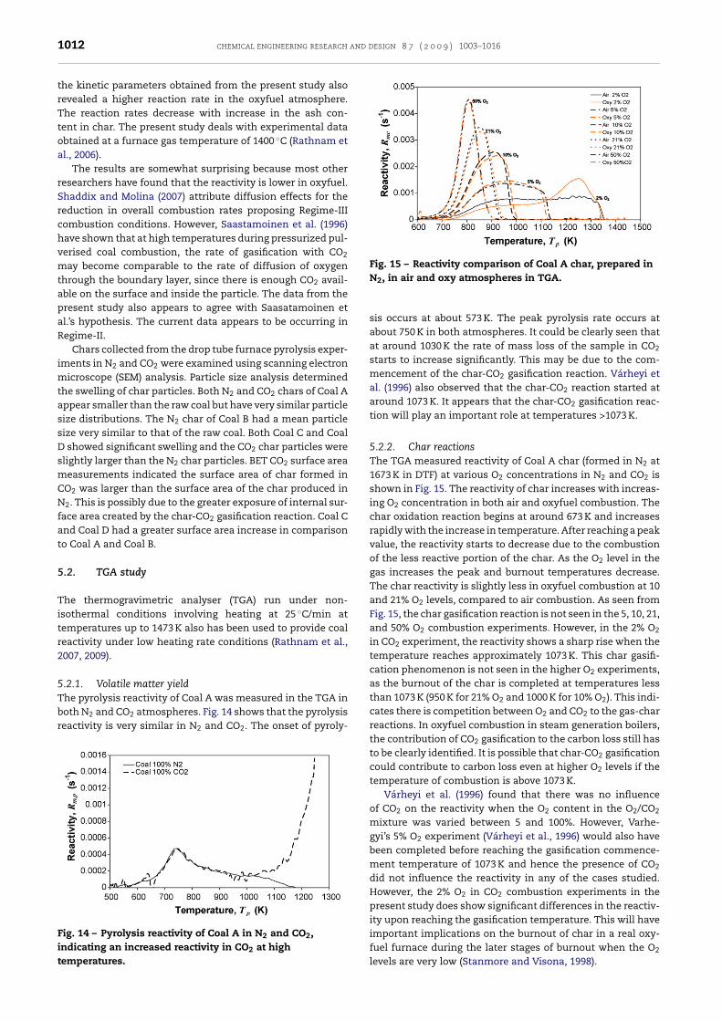
and design 8 7 ( 2 0 0 9 ) 1003–1016
Fig. 15 – Reactivity comparison of Coal A char, prepared in
1012 chemical engineering research
the kinetic parameters obtained from the present study alsorevealed a higher reaction rate in the oxyfuel atmosphere.The reaction rates decrease with increase in the ash con-tent in char. The present study deals with experimental dataobtained at a furnace gas temperature of 1400 ◦C (Rathnam etal., 2006).
The results are somewhat surprising because most otherresearchers have found that the reactivity is lower in oxyfuel.Shaddix and Molina (2007) attribute diffusion effects for thereduction in overall combustion rates proposing Regime-IIIcombustion conditions. However, Saastamoinen et al. (1996)have shown that at high temperatures during pressurized pul-verised coal combustion, the rate of gasification with CO2
may become comparable to the rate of diffusion of oxygenthrough the boundary layer, since there is enough CO2 avail-able on the surface and inside the particle. The data from thepresent study also appears to agree with Saasatamoinen etal.’s hypothesis. The current data appears to be occurring inRegime-II.
Chars collected from the drop tube furnace pyrolysis exper-iments in N2 and CO2 were examined using scanning electronmicroscope (SEM) analysis. Particle size analysis determinedthe swelling of char particles. Both N2 and CO2 chars of Coal Aappear smaller than the raw coal but have very similar particlesize distributions. The N2 char of Coal B had a mean particlesize very similar to that of the raw coal. Both Coal C and CoalD showed significant swelling and the CO2 char particles wereslightly larger than the N2 char particles. BET CO2 surface areameasurements indicated the surface area of char formed inCO2 was larger than the surface area of the char produced inN2. This is possibly due to the greater exposure of internal sur-face area created by the char-CO2 gasification reaction. Coal Cand Coal D had a greater surface area increase in comparisonto Coal A and Coal B.
5.2. TGA study
The thermogravimetric analyser (TGA) run under non-isothermal conditions involving heating at 25 ◦C/min attemperatures up to 1473 K also has been used to provide coalreactivity under low heating rate conditions (Rathnam et al.,2007, 2009).
5.2.1. Volatile matter yield
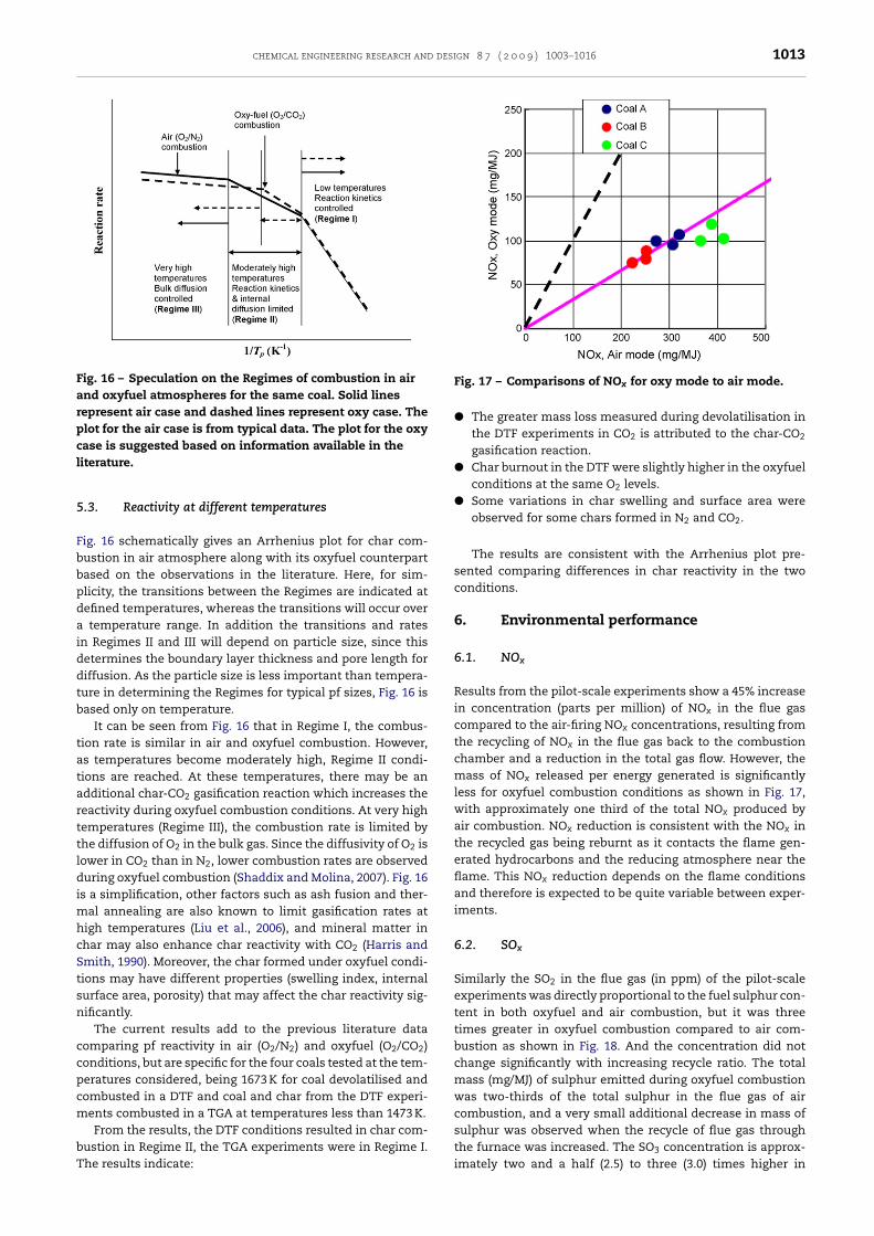
The pyrolysis reactivity of Coal A was measured in the TGA inboth N2 and CO2 atmospheres. Fig. 14 shows that the pyrolysisreactivity is very similar in N2 and CO2. The onset of pyroly-Fig. 14 – Pyrolysis reactivity of Coal A in N2 and CO2,indicating an increased reactivity in CO2 at hightemperatures.
N2, in air and oxy atmospheres in TGA.
sis occurs at about 573 K. The peak pyrolysis rate occurs atabout 750 K in both atmospheres. It could be clearly seen thatat around 1030 K the rate of mass loss of the sample in CO2
starts to increase significantly. This may be due to the com-mencement of the char-CO2 gasification reaction. Várheyi etal. (1996) also observed that the char-CO2 reaction started ataround 1073 K. It appears that the char-CO2 gasification reac-tion will play an important role at temperatures >1073 K.
5.2.2. Char reactionsThe TGA measured reactivity of Coal A char (formed in N2 at1673 K in DTF) at various O2 concentrations in N2 and CO2 isshown in Fig. 15. The reactivity of char increases with increas-ing O2 concentration in both air and oxyfuel combustion. Thechar oxidation reaction begins at around 673 K and increasesrapidly with the increase in temperature. After reaching a peakvalue, the reactivity starts to decrease due to the combustionof the less reactive portion of the char. As the O2 level in thegas increases the peak and burnout temperatures decrease.The char reactivity is slightly less in oxyfuel combustion at 10and 21% O2 levels, compared to air combustion. As seen fromFig. 15, the char gasification reaction is not seen in the 5, 10, 21,and 50% O2 combustion experiments. However, in the 2% O2
in CO2 experiment, the reactivity shows a sharp rise when thetemperature reaches approximately 1073 K. This char gasifi-cation phenomenon is not seen in the higher O2 experiments,as the burnout of the char is completed at temperatures lessthan 1073 K (950 K for 21% O2 and 1000 K for 10% O2). This indi-cates there is competition between O2 and CO2 to the gas-charreactions. In oxyfuel combustion in steam generation boilers,the contribution of CO2 gasification to the carbon loss still hasto be clearly identified. It is possible that char-CO2 gasificationcould contribute to carbon loss even at higher O2 levels if thetemperature of combustion is above 1073 K.
Várheyi et al. (1996) found that there was no influenceof CO2 on the reactivity when the O2 content in the O2/CO2
mixture was varied between 5 and 100%. However, Varhe-gyi’s 5% O2 experiment (Várheyi et al., 1996) would also havebeen completed before reaching the gasification commence-ment temperature of 1073 K and hence the presence of CO2
did not influence the reactivity in any of the cases studied.However, the 2% O2 in CO2 combustion experiments in thepresent study does show significant differences in the reactiv-ity upon reaching the gasification temperature. This will have
important implications on the burnout of char in a real oxy-fuel furnace during the later stages of burnout when the O2levels are very low (Stanmore and Visona, 1998).
chemical engineering research and design 8 7 ( 2 0 0 9 ) 1003–1016 1013
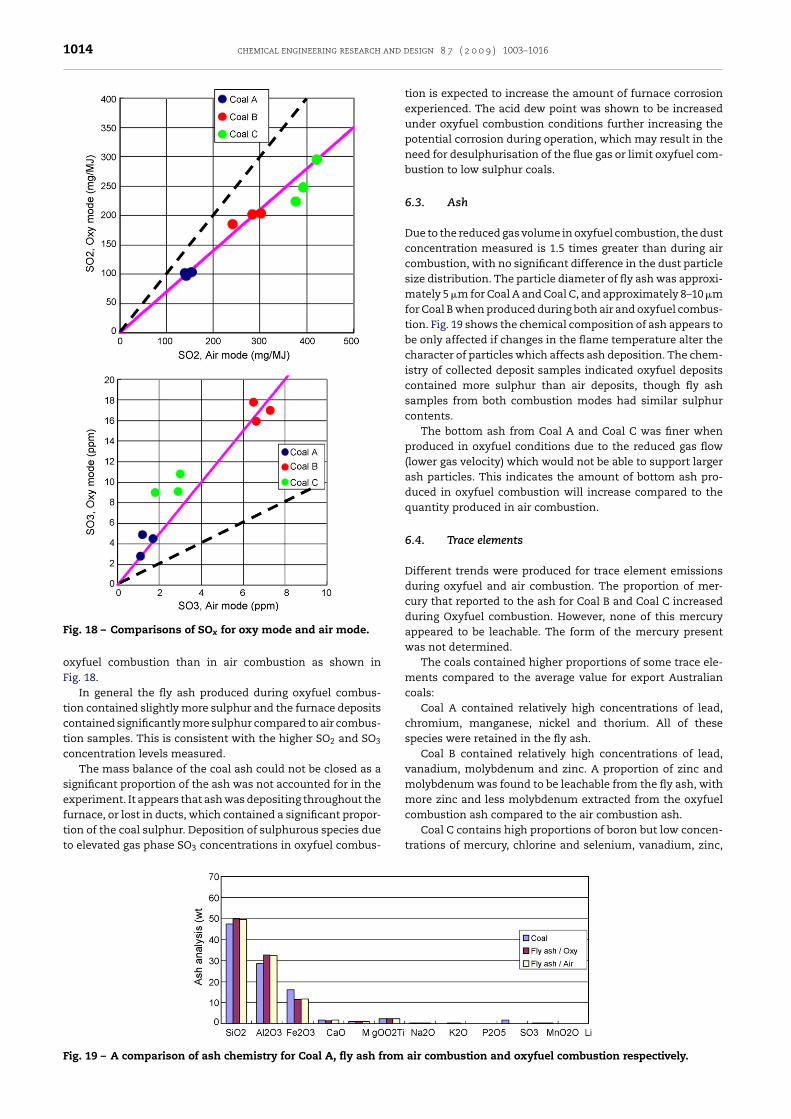
Fig. 16 – Speculation on the Regimes of combustion in airand oxyfuel atmospheres for the same coal. Solid linesrepresent air case and dashed lines represent oxy case. Theplot for the air case is from typical data. The plot for the oxycase is suggested based on information available in thel
5
Fbbpdaiddtb
tatarttldimhcStsn
ccpcm
bT
sulphur was observed when the recycle of flue gas through
iterature.
.3. Reactivity at different temperatures
ig. 16 schematically gives an Arrhenius plot for char com-ustion in air atmosphere along with its oxyfuel counterpartased on the observations in the literature. Here, for sim-licity, the transitions between the Regimes are indicated atefined temperatures, whereas the transitions will occur overtemperature range. In addition the transitions and rates
n Regimes II and III will depend on particle size, since thisetermines the boundary layer thickness and pore length foriffusion. As the particle size is less important than tempera-ure in determining the Regimes for typical pf sizes, Fig. 16 isased only on temperature.
It can be seen from Fig. 16 that in Regime I, the combus-ion rate is similar in air and oxyfuel combustion. However,s temperatures become moderately high, Regime II condi-ions are reached. At these temperatures, there may be andditional char-CO2 gasification reaction which increases theeactivity during oxyfuel combustion conditions. At very highemperatures (Regime III), the combustion rate is limited byhe diffusion of O2 in the bulk gas. Since the diffusivity of O2 isower in CO2 than in N2, lower combustion rates are observeduring oxyfuel combustion (Shaddix and Molina, 2007). Fig. 16
s a simplification, other factors such as ash fusion and ther-al annealing are also known to limit gasification rates at
igh temperatures (Liu et al., 2006), and mineral matter inhar may also enhance char reactivity with CO2 (Harris andmith, 1990). Moreover, the char formed under oxyfuel condi-ions may have different properties (swelling index, internalurface area, porosity) that may affect the char reactivity sig-ificantly.
The current results add to the previous literature dataomparing pf reactivity in air (O2/N2) and oxyfuel (O2/CO2)onditions, but are specific for the four coals tested at the tem-eratures considered, being 1673 K for coal devolatilised andombusted in a DTF and coal and char from the DTF experi-ents combusted in a TGA at temperatures less than 1473 K.From the results, the DTF conditions resulted in char com-
ustion in Regime II, the TGA experiments were in Regime I.he results indicate:
Fig. 17 – Comparisons of NOx for oxy mode to air mode.
� The greater mass loss measured during devolatilisation inthe DTF experiments in CO2 is attributed to the char-CO2
gasification reaction.� Char burnout in the DTF were slightly higher in the oxyfuel
conditions at the same O2 levels.� Some variations in char swelling and surface area were
observed for some chars formed in N2 and CO2.
The results are consistent with the Arrhenius plot pre-sented comparing differences in char reactivity in the twoconditions.
6. Environmental performance
6.1. NOx
Results from the pilot-scale experiments show a 45% increasein concentration (parts per million) of NOx in the flue gascompared to the air-firing NOx concentrations, resulting fromthe recycling of NOx in the flue gas back to the combustionchamber and a reduction in the total gas flow. However, themass of NOx released per energy generated is significantlyless for oxyfuel combustion conditions as shown in Fig. 17,with approximately one third of the total NOx produced byair combustion. NOx reduction is consistent with the NOx inthe recycled gas being reburnt as it contacts the flame gen-erated hydrocarbons and the reducing atmosphere near theflame. This NOx reduction depends on the flame conditionsand therefore is expected to be quite variable between exper-iments.
6.2. SOx
Similarly the SO2 in the flue gas (in ppm) of the pilot-scaleexperiments was directly proportional to the fuel sulphur con-tent in both oxyfuel and air combustion, but it was threetimes greater in oxyfuel combustion compared to air com-bustion as shown in Fig. 18. And the concentration did notchange significantly with increasing recycle ratio. The totalmass (mg/MJ) of sulphur emitted during oxyfuel combustionwas two-thirds of the total sulphur in the flue gas of aircombustion, and a very small additional decrease in mass of
the furnace was increased. The SO3 concentration is approx-imately two and a half (2.5) to three (3.0) times higher in
1014 chemical engineering research and d
Fig. 18 – Comparisons of SOx for oxy mode and air mode.
oxyfuel combustion than in air combustion as shown inFig. 18.
In general the fly ash produced during oxyfuel combus-tion contained slightly more sulphur and the furnace depositscontained significantly more sulphur compared to air combus-tion samples. This is consistent with the higher SO2 and SO3
concentration levels measured.The mass balance of the coal ash could not be closed as a
significant proportion of the ash was not accounted for in theexperiment. It appears that ash was depositing throughout the
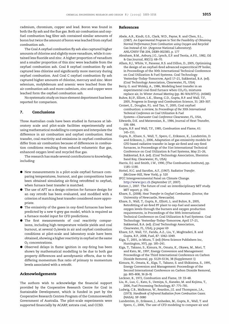
furnace, or lost in ducts, which contained a significant propor-tion of the coal sulphur. Deposition of sulphurous species dueto elevated gas phase SO3 concentrations in oxyfuel combus-Fig. 19 – A comparison of ash chemistry for Coal A, fly ash from
esign 8 7 ( 2 0 0 9 ) 1003–1016
tion is expected to increase the amount of furnace corrosionexperienced. The acid dew point was shown to be increasedunder oxyfuel combustion conditions further increasing thepotential corrosion during operation, which may result in theneed for desulphurisation of the flue gas or limit oxyfuel com-bustion to low sulphur coals.
6.3. Ash
Due to the reduced gas volume in oxyfuel combustion, the dustconcentration measured is 1.5 times greater than during aircombustion, with no significant difference in the dust particlesize distribution. The particle diameter of fly ash was approxi-mately 5 �m for Coal A and Coal C, and approximately 8–10 �mfor Coal B when produced during both air and oxyfuel combus-tion. Fig. 19 shows the chemical composition of ash appears tobe only affected if changes in the flame temperature alter thecharacter of particles which affects ash deposition. The chem-istry of collected deposit samples indicated oxyfuel depositscontained more sulphur than air deposits, though fly ashsamples from both combustion modes had similar sulphurcontents.
The bottom ash from Coal A and Coal C was finer whenproduced in oxyfuel conditions due to the reduced gas flow(lower gas velocity) which would not be able to support largerash particles. This indicates the amount of bottom ash pro-duced in oxyfuel combustion will increase compared to thequantity produced in air combustion.
6.4. Trace elements
Different trends were produced for trace element emissionsduring oxyfuel and air combustion. The proportion of mer-cury that reported to the ash for Coal B and Coal C increasedduring Oxyfuel combustion. However, none of this mercuryappeared to be leachable. The form of the mercury presentwas not determined.
The coals contained higher proportions of some trace ele-ments compared to the average value for export Australiancoals:
Coal A contained relatively high concentrations of lead,chromium, manganese, nickel and thorium. All of thesespecies were retained in the fly ash.
Coal B contained relatively high concentrations of lead,vanadium, molybdenum and zinc. A proportion of zinc andmolybdenum was found to be leachable from the fly ash, withmore zinc and less molybdenum extracted from the oxyfuel
combustion ash compared to the air combustion ash.Coal C contains high proportions of boron but low concen-trations of mercury, chlorine and selenium, vanadium, zinc,
air combustion and oxyfuel combustion respectively.
desi
cbfbc
ataococsal
r
7
Toudtdte
i
�
�
�
�
�
A
TpSCGs
chemical engineering research and
admium, chromium, copper and lead. Boron was found inoth the fly ash and the flue gas. Both air combustion and oxy-uel combustion bag filter ash contained similar amounts oforon but twice the amount of boron was leached from oxyfuelombustion ash.
The Coal A oxyfuel combustion fly ash also captured highermounts of chlorine and slightly more vanadium, while it con-ained less fluoride and zinc. A higher proportion of vanadiumnd a smaller proportion of this zinc were leachable from thexyfuel combustion ash. Coal B oxyfuel combustion fly ashaptured less chlorine and significantly more mercury duringxyfuel combustion. And Coal C oxyfuel combustion fly ashaptured higher amounts of chlorine, mercury and zinc. Moreelenium, molybdenum and arsenic were leached from their combustion ash and more cadmium, zinc and copper wereeached form the oxyfuel combustion ash.
No systematic study on trace element deportment has beeneported for comparison.
. Conclusions
hree Australian coals have been studied in furnaces at lab-ratory scale and pilot-scale facilities experimentally andsing mathematical modelling to compare and interpolate theifference in air combustion and oxyfuel combustion. Heatransfer, coal reactivity and emissions in oxyfuel combustioniffer from air combustion because of differences in combus-ion conditions resulting from reduced volumetric flue gas,nhanced oxygen level and recycled flue gas.
The research has made several contributions to knowledge,ncluding:
New measurements in a pilot-scale oxyfuel furnace com-paring temperatures, burnout, and gas compositions havebeen obtained simulating air-firing retrofitted to oxyfuel,when furnace heat transfer is matched.The use of AFT as a design criterion for furnace design foran oxy retrofit has been evaluated, and modified with acriterion of matching heat transfer considered more appro-priate.The emissivity of the gases in oxy-fired furnaces has beenpredicted by a new 4-grey gas model, which is required asa furnace model input for CFD predictions.The first measurements of coal reactivity compar-isons, including high-temperature volatile yields and coalburnout, at several O2levels in air and oxyfuel combustionconditions at pilot-scale and laboratory scale have beenobtained, showing a higher reactivity in oxyfuel at the sameO2 concentrations.Observed delays in flame ignition in oxy-firing has beenshown by mathematical modelling to be due to both gasproperty differences and aerodynamic effects, due to thediffering momentum flux ratio of primary to momentumlevels associated with a retrofit.
cknowledgements
he authors wish to acknowledge the financial supportrovided by the Cooperative Research Centre for Coal in
ustainable Development, which is funded in part by theooperative Research Centres Program of the Commonwealthovernment of Australia. The pilot-scale experiments wereupported financially by ACARP, xstrata coal, and CCSD.gn 8 7 ( 2 0 0 9 ) 1003–1016 1015
References
Abele, A.R., Kindt, G.S., Clark, W.D., Payne, R. and Chen, S.L.,(1987). An Experimental Program to Test the Feasibility of ObtainingNormal Performance from Combustion using Oxygen and RecycledGas Instead of Air. (Argonne National Laboratory).ANL/CNSV-TM-204, DE89-002383, p. 177
Abraham, B.M., Asbury, J.G., Lynch, E.P. and Teotia, A.P.S., 1982, Oil& Gas Journal, 80(11): 68–70.
Allam, R.J., White, V., Panesar, R.S. and Dillon, D., 2005, Optimisingthe design of an oxyfuel-fired advanced supercritical PF boiler,in Proceedings of the 30th International Technical Conferenceon Coal Utilization & Fuel Systems. Coal Technology:Yesterday–Today–Tomorrow, April 17–21, Sakkestad, B.A. (ed).(Coal Technology Association, Clearwater, FL, USA)
Berry, G. and Wolsky, A., 1986, Modeling heat transfer in anexperimental coal-fired furnace when CO2/O2 mixturesreplace air, In Winter Annual Meeting (pp. 86-WA/HT51). (ASME)
Buhre, B.J.P., Elliott, L.K., Sheng, C.D., Gupta, R.P. and Wall, T.F.,2005, Progress in Energy and Combustion Science, 31: 283–307.
Croiset, E., Douglas, P.L. and Tan, Y., 2005, Coal oxyfuelcombustion: a review, In Proceedings of the 30th InternationalTechnical Conference on Coal Utilization & FuelSystems—Clearwater Coal Conference Clearwater, FL, USA,
Edwards, D.K. and Matavosian, R., 1984, Journal of Heat Transfer,106: 684.
Gupta, R.P. and Wall, T.F., 1985, Combustion and Flame, 61:145–151.
Gupta, R., Khare, S., Wall, T., Spero, C., Eriksson, K., Lundström, D.and Eriksson, J., 2006, Adaptation of gas emissivity models forCFD based radiative transfer in large air-fired and oxy-firedfurnaces, in Proceedings of the 31st International TechnicalConference on Coal Utilization & Fuel Systems, May 21–26,Sakkestad, B.A. (ed). (Coal Technology Association, SheratonSand Key, Clearwater, FL, USA)
Harris, D.J. and Smith, I.W., 1990, (The Combustion Institute), pp.1185–1190.
Hottel, H.C. and Sarofim, A.F., (1967). Radiative Transfer.(McGraw-Hill, New York), p. 520
IPCC Intergovernmental Panel on Climate Change.http://www.ipcc.ch (September 27, 2007).
Katzer, J., 2007. The future of coal: an interdisciplinary MIT study.MIT report; p. 192.
Khare, S., (2008). Heat Transfer in Oxyfuel Combustion. (Doctor, theUniversity of Newcastle, Newcastle).
Khare, S., Wall, T., Gupta, R., Elliott, L. and Buhre, B., 2005,Retrofitting of air-fired PF plant to oxy-fuel and associatedoxygen levels through the burners and oxygen productionrequirements, in Proceedings of the 30th InternationalTechnical Conference on Coal Utilization & Fuel Systems. CoalTechnology: Yesterday–Today–Tomorrow, April 17–21,Sakkestad, B.A. (ed). (Coal Technology Association,Clearwater, FL, USA), p paper 69
Khare, S.P., Wall, T.F., Farida, A.Z., Liu, Y., Moghtaderi, B. andGupta, R.P., 2008, Fuel, 87: 1042–1049.
Kiga, T., 2001, in Miura, T. (ed) (Nova Science Publishers Inc,Huntington, NY), pp. 185–241.
Kiga, T., Takano, S., Kimura, N., Omata, K., Okawa, M., Mori, T.and Kato, M., 1997, Energy Conversion and Management:Proceedings of the Third International Conference on CarbonDioxide Removal, pp. S129–S134, 38 (Supplement 1)
Kimura, N., Omata, K., Kiga, T., Takano, S. and Shikisima, S., 1995,Energy Conversion and Management: Proceedings of theSecond International Conference on Carbon Dioxide Removal,pp. 805–808, 36 (6–9)
Leckner, B., 1972, Combustion and Flame, 19: 33–48.Liu, H., Luo, C., Kato, S., Uemiya, S., Kaneko, M. and Kojima, T.,
2006, Fuel Processing Technology, 87: 775–781.Ludwig, C.B., Malkmus, W., Reardon, J.E. and Thompson, J.A.,
(1973). Handbook of Infrared Radiation from Combustion Gases.
(NASA). SP-3080Lundström, D., Eriksson, J., Anheden, M., Gupta, R., Wall, T. andSpero, C., 2006, The use of CFD modeling to compare air and

and d
1016 chemical engineering researchoxy-firing of a retrofitted pulverized fuel boiler, in Proceedingsof the 31st International Technical Conference on CoalUtilization & Fuel Systems, May 21–26, Sakkestad, B.A. (ed)Clearwater, FL, USA,. (Coal Technology Association)
Nakayama, S., Noguchi, Y., Kiga, T., Miyamae, S., Maeda, U.,Kawai, M., Tanaka, T., Koyata, K. and Makino, H., 1992, EnergyConversion and Management, 33(5–8): 379–386.
Nozaki, T., Takano, S., Kiga, T., Omata, K. and Kimura, K., 1997,Energy, 22(2/3): 199–205.
Payne, R., Chen, S.L., Wolsky, A.M. and Richter, W.F., 1989,Combustion Science and Technology, 67: 1–16.
Rathnam, R.K., Elliott, L., Moghtaderi, B., Gupta, R. and Wall, T.,2006, Differences in coal reactivity in air and oxy-fuelconditions and implications for coal burnout, in Proceedingsof the 31st International Technical Conference on CoalUtilization & Fuel Systems, May 21–26, Sakkestad, B.A. (ed)Clearwater, FL, USA,. (Coal Technology Association)
Rathnam, R.K., Moghtaderi, B. and Wall, T., 2007, Differences inpulverised coal pyrolysis and char reactivity in air (O2/N2) andoxy-fuel (O2/CO2) conditions, in Proceedings of the 32ndInternational Technical Conference on Coal Utilization & FuelSystems, June 10–15, Sakkestad, B.A. (ed) Clearwater, FL, USA,
Rathnam, R.K., Elliott, L., Wall, T., Liu, Y., Moghtaderi, B., 2009.Fuel Processing Technology, in press.
Khare, S., Wall, T., Abdulgani, Z., Liu, Y., Moghtaderi, B. andGupta, R., 2007, Comparison of the ignition of oxy-fuel andair-fired PF flames, In Proceedings of the 24th AnnualInternational Pittsburgh Coal Conference, September 10–14.(Sandton Convention Centre, Johannesburg, South Africa)
Khare, S.P., Farida, A.Z., Wall, T.F., Liu, Y. and Moghtaderi, B., 2007,Factors influencing the ignition of flames from air fired swirlPF burners retrofitted to oxy-fuel, in Proceedings of the 32ndInternational Technical Conference on Coal Utilization & FuelSystems, June 10–15, Sakkestad, B.A. (ed) Clearwater, FL, USA,
Saastamoinen, J.J., Aho, M.J. and Hamalainen, J.P., 1996, Energy &Fuels, 10: 121–133.
Santos, S., Haines, M. and Davison, J., 2006, Challenges in the
development of oxy-combustion technology for coal firedpower plant, in Proceedings of the 31st InternationalTechnical Conference on Coal Utilization & Fuel Systems,esign 8 7 ( 2 0 0 9 ) 1003–1016
Sakkestad, B.A. (ed). (Coal Technology Association, SheratonSand Key, Clearwater, FL, USA), p. 1
Shaddix, C.R. and Molina, A., 2007, Influence of CO2 on coal charcombustion kinetics in oxy-fuel applications, In Proceedings ofthe 5th US Combustion Meeting Organized by the Western StatesSection of the Combustion Institute. (The University of Californiaat San Diego, 2007, The University of California at San Diego)
Smith, T.F., Shen, Z.F. and Friedman, J.N., 1982, Journal of HeatTransfer, 104: 602–608.
Spero, C., 2007, Status of calide (30 MWe) oxyfuel project, In 2ndWorkshop of the Oxy-fuel Combustion Network, January 25–26.(Hilton Garden Inn, Windsor, Conneticuct)
Stanmore, B.R. and Visona, S.P., 1998, Combustion and Flame,113: 274–276.
Wall, T., 2007, Performance of PF burners retrofitted to oxy-firing,In 2nd Workshop of the Oxy-fuel Combustion Network, January25–26. (Hilton Garden Inn, Windsor, Conneticuct)
Wall, T.F., 2007, Combustion processes for carbon capture, InProceedings of the Combustion Institute , pp. 31–47
Várheyi, G., Szabó, P., Jakab, E. and Till, F., 1996, Energy & Fuels,10: 1208–1214.
Wall, T., 2005, Fundamentals of oxy-fuel combustion, In InauguralWorkshop of the Oxy-fuel Combustion Network, November 29–30Cottbus, Germany,
Wang, C.S., Berry, G.F., Chang, K.C. and Wolsky, A.M., 1988,Combustion and Flame, 72: 301–310.
Weller, A.E., Rising, B.W., Boiarski, A.A., Nordstrom, R.J., Barrerr,R.E. and Luce, R.G., (1985). Experimental Evaluation of FiringPulverized Coal in a CO2/O2 atmosphere. (Argonne NationalLaboratory). ANL/CNSV-TM-168
White, C.M., Strazisar, B.R., Granite, E.J., Hoffman, J.S. andPennline, H.W., 2003, Journal of the Air & Waste ManagementAssociation, 53(6): 645–715.
Yamada, T., Tamura, M., Fujimori, T., Khare, S., Wall, T.F.,Isherwood, B. and Spero, C., 2006, Comparison of combustioncharacteristics of between oxy-fuel and air combustion, inProceedings of the 31st International Technical Conference on
Coal Utilization & Fuel Systems, May 21–26, Sakkestad, B.A.(ed). (Coal Technology Association, Sheraton Sand Key,Clearwater, FL, USA), p. 17