Embed Size (px)
Citation preview

PUBLICATION
Division of Water
~s c
An OwnersGuidance ManualFor the Inspectionand Maintenance
of Dams in New York State
June 1987
New York State/Department of Environmental Conservation

:E
FOREWORD
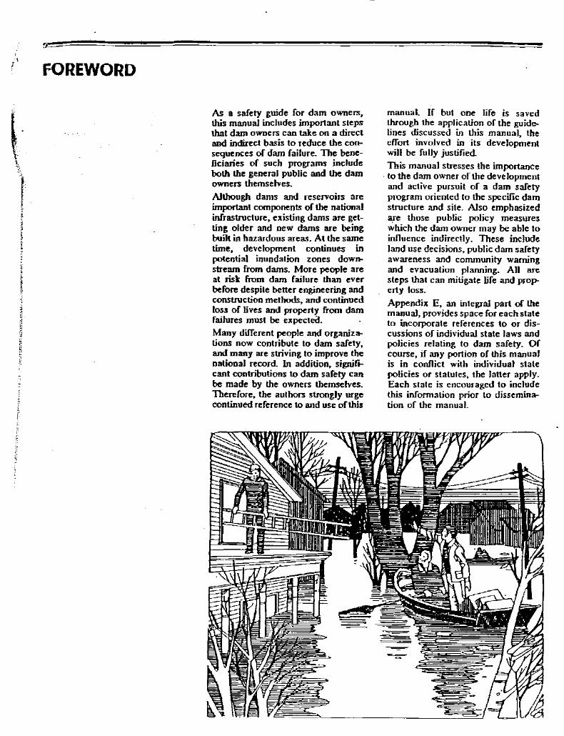
As a safety guide for dam owners,this manual includes important stepsthat dam owners can lake on a directand indirect basis to reduce the consequences of dam failure. The beneficiaries of such programs includeboth the general public and the damowners themselves.Although dams and reservoirs areimportant components of the nationalinfraslnIcture, existing dams are getting older and new dams are beingbuilt in hazardous areas. At the sametime, - development continues inpotential inundation zones downstream from dams. More people areat rist from dam failure than everbefore despite better engineering andconstruction methods, and continuedloss of lives and property from damfailures must be expecteil.Many different people and organiz:otions now contribute to dam safety,and many are striving to improve thenational record. In addition, signiftcant contributions to dam safety canbe made by the owners themselves.Therefore, the authors strongly urgecontinued reference to and use of this
manual. If but one life is savedthrough the application of the guidelines discussed in this manual, theeffort involved in its developmentwill be fully justified.This manual stresses the importance
. to the dam owner of the developmentand active pursuit of a dam safetyprogram oriented to the specific damslnIcture and site. Also emphasizedare those public policy measureswhich the dam owner may be able toinIluence indirectly. These includeland use decisions, public dam safetyawareness and conununity warningand evacuation planning. All aresteps that can mitigate life and property loss.
Appendix E, an integral part of themanual, provides space for each stateto incorporate references to or discussions of individual state laws andpolicies relating to dam safety. Ofcourse, if any portion of this manualis in conflict with individual statepolicies or statutes, the latter apply.Each slale is encouraged to includethis information prior to dissemin:otion of the manual.

ACKNOWLEDGEMENTS
This dam owner's guidance manua)·isthe result ofthe work ofmany peopleand organizations. The Federal Emergency Management Agency suppliedthe impetus and fuuding fur the pro}ecL The Colorado Division of Disaster Emergency Services (DODES)(John P. Byrne, Director) undertookthe actual development of the manualand contributed several of the chapters. Jeris A. Danielson, ColoradoState Engineer ,and John P. Byrneserved as Co-chairmen of the technical advisory commillee. PatriciaHagan, DODES Project Officer, ledthe development and writing learn ofJack Truby, DODES and ProfessorsLynn Johnson P.E. and Charles Bartholomew P.E. (University of Colorado at Denver, Department of CivilEngineering). Hal Simpson, Colorado Deputy State Engineer, also provided direction and assislance.Development ofthis national manualwould not have been possible withouldrawing from the excellent damsafety manuals now in use by manystates. In particular, the followingstates provided considerable assistance: Arkansas, Colorado, Kentucky, North Carotina, North Dakota,Ohio, Pennsylvania, Virginia andWyoming; also, STS Consultanls.The Colorado, Ohio, and Pennsylvania manuals were particularlyhelpful and supplied many ofthe engineering fundementals andgraphics.
•
The authors are indebted 10 the cochairmen and the members of thetechnical advisory commillee ofdamsafety officials - group representing awide range of expertise and localinsighls - who helped define dam·owners' needs and thus, the scope ofthis book.
John Molt - ColoradoJohn Diebel - ColoradoJ arneS Doody - CatiforniaJoseph Ellam - PennsylvaniaCharles Gardner - North CarotinaDan Robert Lawrence - ArizonaWilliam Riebsame - ColoradoSpecial thanks are extended to BillRiebsarne, University of Colorado, .Johan Stolpe and David Butler, aswell as Steve Slane and DeborahHanderhan, from the Colorado StateDesigo Center,- who contribuied si~
nilicantly to the graphic production.The production tearn could not haveaccomplished such a large lask without the support of Irwin Glassman,DODES Planning Chief, and theentire DODES staff. Special recognition goes to Nora Rimando for herdedication, creativity and insight intyping the manual.

DAM SAFElY:AN OWNER'SGUIDANCE MANUALEXECUTIVE SUMMARY12/86
AN APPROACH TODAM SAFETYThere is an urgent and continuingneed for dam safety in the UnitedStates because of thousands of damsare now in place across the U.S. andmany more are being built each year.These dams are essential elements ofthe national infrastructure, but thepublic risk in case offailure is great;large and growing numbers of livesand valuable properties are at stake.Although there are many who areconcerned about dam safety, legaland moral responsibility essentiallyrests with the dam owner.
Dam owners serve society by meeting important national needs and ofcourse,. may also profit from damoperations. However? these reasonsdo not justify the utility and effectiveness ofownership ifthe owner cannotprovide safety for people and pro!>erty. The costs of dam safety aresmall in comparison 10 those whichfollow dam failure, particularly in ourmodem "litigious" society. Liabilitydue to failure could easily offsetyears of profitabilily.The dam owner can directly inJJuencethe safety of a dam. Owners can andshould develop Iheir own safety prlrgram which includes such importanIelements as inspectin~ monitoring.through instrumentation, maintainingthe structure, emergency action planning and operating. Such a programis directly related to the dam structure and its immediate environmentand depends on the owner's knowledge of the dam and how it works.
INTRODUCTION TO DAMSDams may be either man-made orexist because of natural phenomena,such as !andslides or glacial deposition. The majority of dams are manmade structures nonnaJly constructedof earthfill or concrete. It is important that a dam owner be aware of thedifferent types of dams, essentialcomponent parts of a dam, important
physical conditions likely to inJJuencethe dam, and how the key components function.
HAZARDS, RISK, FAILURESPresent national loss statistics fromdam failure fully justifY the need fordam owners to better understand thepublic risks involved with damownership, the kinds of hazards thatpromote these risks and the reasonswhy dams fail. Public risk is highbecause people have been allowed tosettle below dams in potential inundation zones and because new damsare being built in less than idealsites~
Other elements of risk include naturalphenomena such as l100ds, earthquakes and landstides. These hazardsthreaten dam structures and their surroundings. Floods that exceed thecapacily ofa dam's spillway and thenerode the dam or abutments are particularly hazardous, as. is seismicactivity that may cause cracking orseepage. Similarly, debris from landslides may block a. dam's spillwayand cause an overflow wave thaterodes the abutments and ultimatelyweaken the structure~
The International Commission ofLarge Darns (ICOLD) has delermined that the three major categoriesor dam failure are overtopping by1100d, foundation defects and piping.For earthen dams, the major reasonfor failure was piping or seepage. Forconcrete dams, the major reasons forfailure were associated with foundations. Overtopping was a significant cause ofdam failure primarily incases where there was an inadequatespillway.
DEVELOPING A DAM SAFETYPROGRAMRecognition of ihe causes and possible impacts of dam failure points oulthe need for a program to enhancedam safety. Such a program must bebased on a safely evaluation to deter-

mine a dam?s structural and operational safety. The evaluation shouldidentify problems and recommendeither remedial repairs? operationalrestrictions and modifications? or further analyses and studies to determinesolutions.A safety program comprises severalcomponents that address the spectrum of possible actions to be takenover the short and long term. Development of a safety program involvesa phased process beginning withcollection and review of existinginformation, proceeding to detailedinspections and analyses, and cuImin ating with formal documentation.Much of the preliminary work can beaccomplished by the dam owner withthe assistance of state and localpublic agencies. However, dependingupon the number and seriousness ofproblems identified by the initialassessmen~ professional assistanceby qualified engineers and contractors may be required
Information presented in this manualprovides direction on how to proceedwith establishing an action to increasethe safety of a dam. The discussiondetails technical and proceduralcomponents of the safety program,and necessary forms are provided
The program of inspection for boththe initial and continuing safetyevaluations establishes the conditionof the dam and provides the information necessary for determining specificactions to be taken regarding repairs,operations, and monitoring. The program is cyclical recognizing the needfor continued vigilance. Emergencyaction can hopefully be avoided, buta well thought out plan of action incase of imminent or actual failure cangreaUy reduce damage and possibleloss of life.
INSPECTION GUIDELINESAn effective inspection program isessential to identify problems and toprovide for safe maintenance of adam. The inspection program shouldinvolve three types of inspections:(I) periodic technical inspections,(2) periodic maintenance inspections, and (3) informal observationsby project personnel as they operatethe dam. Technical inspections involve specialists familiar with thedesign and construction of dams andinclude assessments of structuresafety. Maintenance inspections areperformed more frequently than
technical inspections in order todetect, at an early stage, any detrimental developments in the dam;they involve assessment of operational capability as well as structuralstability. The third type ofinspectionis actually a continuing eITort by onsite project personnel (dam tenders,powerhouse operators? maintenancepersonnel) performed in the course oftheir normal duties.
INSTRUMENTATIONAND MONITORINGGUIDELINESInstrumeritation of a dam furnishesdata to determine if the ·completedstructure is functioning as intended 'and provides a continuing sur-'veillance of the structure to warn ofany unsafe developments.
Means and methods available tomonitor physical phenomena thatcan lead to a dam failure include awide spectrum of instruments andprocedores ranging from very si",pleio very complex. Any program ofdam safety instrumentation mustinvolve proper design consistent withother project components, must bebased on prevailing geotechnicalconditions at the dam, and mustinclude consideration of the hydre>logic and hydraulic factors presentboth before and aIIer the project is inoperation. Instrumentation designedfor monitoring potential deficienciesat existing dams must take intoaccount the threat to life and property that the dam presents. Thus, theextent and nature ofthe instrumentation depends not only on the complexity of the dam and the size of thereservoir, but also on the potential forloss of life and property downstream.
An instrumentation program shouldinvolve instruments and evaluationmethods that are as simple andstraightforward as ~e project willallow. Moreover, the dam ownershould make a defmite commitment toa continuing monitoring program; ifthe program is not continuing, theinstallation of instruments and procedures will be wasted. Obviously, theinvolvement of qualified personnel inthe design? installation, monitoring,and evaluation of an instrumentationsystem is of prime importance to thesuccess of the programInstrumentation and proper monitoring and evaluation are extremelyvaluable in determining the performance of a dam. Specific information
that instrumentation can provideincludes:
• Warning of a problem.• Definition of and analyzing a
problem• Proof that behavior is as expected• Remedial action perfonnance
evaluation
MAINtENANCE GUIDELINESA good maintenance program willprotect a dam against deteriorationand prolong its life. A poorly maintained dam will deteriorate and canfail. Nearly all the components of adam and the materials used for damconstruction are susceptible to damaging deterioration if not properlymaintained. A good maintenanceprogram provides not only protectionfor the owner, but for the generalpublic as well. Furthermore, the costof a proper maintenance program issmall compared to the cost of majorrepairs or the loss of life and propertyand resultant litigation against thedam owner. A dam owner shoulddevelop a basic maintenance program based primarily on systematicand frequent inspections. Inspections, as noted in Chapter 5, sho~ldbe done monthly and after majornood or earthquake events. Duringeach inspection, a checklist of itemscalling for maintenance should beused.
EMERGENCY ACTION PLANGUIDELINESAlthough most dam owners have ahigh level of confidence in the structures they own and are certain theirdams will not f.il. history has shownIhat on occasion dams do faii and thatonen these failures cause loss of lire~
injuries and extensive property damage. A dam owner should prepare for.this possibility by developing anemergency action plan which pre>vides a systematic means to:
• Identify emergency conditionsthreatening a dam
• Expedite effective response actionsto prevent failure
• Reduce loss of life and propertydamage should failure occur
A dam owner is responsible for preparing a plan covering these measuresand listings actions that the ownerand operating personnel should take.He should be familar with the localgovernment officials and agenciesresponsible for warning and evacuating the public.

Itis important that dam owners makefull use of others who are concernedwith dam safety; emergency plans,will be more effective if they integratethe actions ofothers who can expediteresponse. People and organizationswith whom the dam owner shouldconsuh in preparing an emergencyaction plan include nwnerous localparticipants, state and federalagencies.
An essential part of the emergencyaction plan is a list of agencieslpersons to be notified in the event ofapotential failure. Possible inclusionsfor this list should be obtained·fromand coordinated with local lawenforcement agencies and local disasteremergency services. These are keypeople or agencies who can activatepublic warning and evacuation procedures or who might be able to assistthe dam owner in delaying or preventing failure.
Certain key elements must be includedin every notification plan. Information about potential inundation (Droding) areas and travel times for thebreach (0000) wave is essential.Inundation maps are especially useful in local warning and evacuationplanning. Detailed information aboutidentification of inundation areas orthe development of maps can befound by contacting the StateEngineer's Office or local planningoffices.
OPERATIONS PLANGUIDELINES
Establishing an operations procedureor plan calls for detailed:
• Dam and reservoir physical characteristiCs data
• Descriptions of dam components• Operations instructions for oper
able mechanisms• Inspection instructions• Instrumentation and monitoring
guidelines• Maintenance operations guidelines• Emergency operations guidelines• Bibliographical informationA schedule should be established toinclude both day-to-day tasks andtasks performed less frequentlythroughout the year. The schedulefonnalizes inspection and maintenance procedures so that even aninexperienced person can detenninewhen a task is to be done.
MEASURES TO REDUCE THECONSEQUENCES OF DAMFAILUREliabilities which are determined following a dam failure strongly affectboth organizations and individuals t
governments and dam owners. Esta~lishing liability is the legal meansdeveloped by society to recoverdamages due to a "wrong>? (in thiscase, lack of dam safety) and reJ>resents another perspective on thedam safety problem. A thoroughunderstanding of this legal processcan help the dam owner decide thesteps to be taken to reduce liability.
The darn owner can directly andindirectly influence the introductionand use ofa variety ofother measuresthat will serve to reduce the consequences ofdam failure. For example,insurance against the costs which willaccrue after a failure will save thedam owner money by spreading costsfrom a single dam_ owner to others.Some land use measures instituted bygovenunents represent better meansof mitigating future disasters. If people are restricted from living in inundation zones, then safely is radicallyimproved Instituting land use measures represents one of the mosteffective ways to save lives and property over the long term, but such stepsare not always acceptable to governments. Thus, given that lives andproperty are at stake, increasingputJIjc awareness an~ gove"rnmentalplanning are vital measures that alsomust be considered as ways to reducethe consequences of darn failure.Dam owners can obtain insurancedirectly 3J!d should do so. The othermeasures discussed here -- land use,.public awareness and preparednessplanning - are essentially controlledby local governments. Therefore,darn owners would be wise to encourage as strongly as possi!>le awarenessand action in the public sector.Finally, they may also wish to hireconsultants from the private sectorwhen the informalion needed for prudent decisions exceeds their ownexpertise.

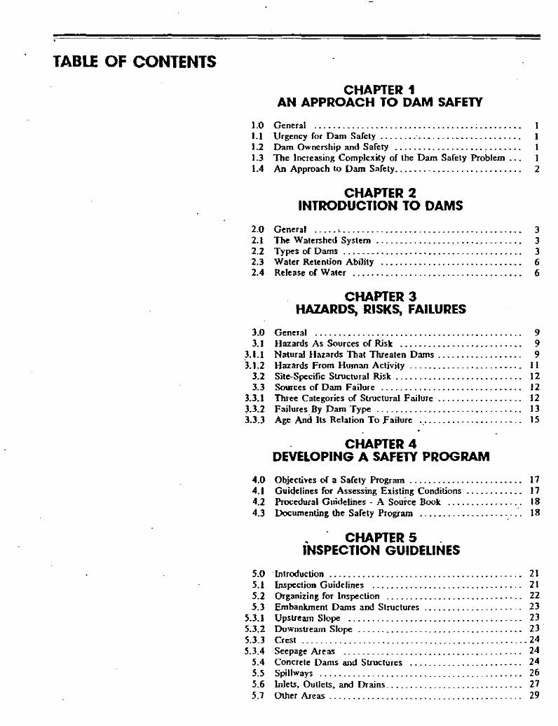
TABLE OF CONTENTS
CHAPTER 1AN APPROACH TO DAM SAFETY
1.0 General ...........................................• I1.1 Urgency for Dam Safety I1.2 Dam Ownership and Safety I1.3 The Increasing Complexity of the Dam Safety Problem '" I1.4 An Approach to Dam Safety.... . . . . . . . . . . . . . . . . . . . . . . . 2
CHAPTER 2INTRODUCTION TO DAMS
2.0 General .....• . . . . . . . . . . . . . . . . . . . . . . . . . . . . . . . . . . . . . . 32.1 The Walershed System 32.2 Types of Dams 32.3 Water Retention Ability ........•....................• 62.4 Release of Water .........•.......................... 6
CHAPTER 3HAZARDS, RISKS, FAILURES
3.0 General 93.1 Hazards As Sources of Risk 9
3.1.1 Natural Hazards That Threaten Dams 93.1.2 Hazards From Human Activity II
3.2 Site-Specific SlnJctural Risk 123.3 Sources of Dam Failure 12
3.3.1 Three Categories of SlnJctural Failure................ .. 123.3.2 Failures By Dam Type 133.3.3 Age And Its Relation To l'ailure 15
CHAPTER 4DEVELOPING A SAFETY PROGRAM
4.0 Objectives of a Safety Program 174.1 Guidelines for Assessing Existing Conditions 174.2 Procedural Guidelines - A Source Book 184.3 Documenting the Safety Program 18
. CHAPTER 5 .INSPECTION GUIDEUNES
5.0 'Introduction 215.1 Inspection Guidelines 215.2 Organizing for Inspection 225.3 Embankment Dams and Structures 23
5.3.1 Upstream Slope 235.3.2 Downstream Slope 235.3.3 Crest 245.3.4 'Seepage Areas 24
5.4 Concrele Dams and SlnJctiJres 245.5 Spillways... . . . . . . . . . . . . . . . . . . .. . . .. . . . . . . . . . . . . . . .. 265.6 Inlets, OuUets, and Drains.. . . . . . . . . . . . . . . . . .. .. . . . . . .. 275.7 Other Areas '" . . . . .. .. .. . .. 29
CHAPTER 6INSTRUMENTATION AND MONITORING
GUIDELINES
6.0 General 516.1 Reasons for Instrumentation 516.2 Instrument Types and Usage 52
6.2.1 Visual Observations .................................• 526.2.2 Movement ...................................•...•.. 526.2.3 Pore Pressure and Uplift Pressure 546.2.4 Water Level and Flow 556.2.5 Seepage Flow 556.2.6 Water Quality 556.2.7 Temperature .....................................•.. 566.2.8 Crack and Joint Size 566.2.9 Seismic Activity 57
6.2.10 Weather and Precipitation 576.2.11 Stress and Strain 57
6.3 Frequency of Monitoring 57
CtiAPTER 7MAINTENANCE GUIDEUNES
7.0 General 617.1 Maintenance Priorities. 61
7.1.1 Immediate Maintenance 617.1.2 Required Maintenance at Earliest Possible Date 617.].3 Continuing Maintenance 61
7.2 Specific Maintenance Items 62·7.2.1 Earthwork Mainlenance and Repair 627.2.2 Riprap Maintenance and Repair 637.2.3 Vegetation Maintenance :... 647.2.4 Livestock Control 647.2.5 Rodent Damage Control 647.2.6 Traffic Damage Control 657.2.7 Mechanical Maintenance........ .. .. 657.2.8 Electrical Maintenance 667.2.9 Cleaning :.. . . . . . . . . . . . . . . .. . . . . . . .. 66
7.2.10 Concrete Maintenance 667.2.11 Metal Component Maintenance 66
•CHAPTER 8
EMERGENCY ACTION PLAN GUIDEUNES
8.0 The Emergency Aclion Plan : 698.1 Identification of Emergency Conditions and Initiation of
Emergency Response Actions 708.2 Guidelines for Emergency Notification 71

CHAPTER 9OPERATIONS GUIDEUNES
9.0 General .......................•.................... 759.1 Operations Plan Guidelines ...•.••..••.••...........•. 75
9.1.1 Background Data ...•...•..•.........•..•.......•.... 759.1.2 Operations Instructions and Records ...•.........•..... 76
9.2 Schedule of Routine Tasks .•..••••••.••.•.....••...... 769.3 Record Keeping .......••...••.••••.•........... '" . .. 76
CHAPTER 10REDUCING THE CONSEQUENCES OF DAM FAILURE
10.0 Supplements to a Dam Safety Program ,................ 7910.1 Liability. . . . . . . . . . . . . • • . • . • . . . . . . • . . • . . . . . . . . . . • . . •. 7910.2 Measures to Reduce the Consequences of Dam Failure... 80
10.2.1 Insurance. . . . . . . . . . . . . . . . . . . . . . . . . . . . . . . . . . . . . . . . . .. 8010.2.2 Governmental Assistance '.' . . . . . . . . . . . . . . . . . . . .. 8110.2.3 Consultants Role in Dam Safely 82
APPENDIXES
A Inspection Forms ..............•...........•......... 83B Report Form ..........•.......••.•..••.•••••.•...••. 95C Glossary. . . . . . . . . . . . . . . . • . . . • . • . . . . . . . . . . . . . . . . . . . .. 99D Selected Bibliography .......••..••••.•..•..•..•...... 113E State Background and Perspective .......•.............. 117
•

UST OF TABLES
Table 1.1 Loss of Life and Property from Notable U.S. DamFailures .................................• . . . . . . . . . . 2
3.1 Hazard Potential Classification for Dams 113.2 Examples of Earthen Dam Failures 153.3 Examples of Concrete Dam Failures 155.1 Inspection Guidelines Directory ...............•. :..... 195.2 Inspection Equipment and lis Use 226.1 . Instrumentation and Monitoring Guidelines Directory. . . .. 497.1 Maintenance Guidelines Directory 598.1 Emergency Action Guidelines Directory ....•........•.. 678.2 Potential Problems and Immediate Response Actions ... 70-718.3 Checklist for Dam Emergency Plans :..... 729.1 Operation Plan - Schedule of Routine Tasks 77
10.1 Comparison of Warning Success for Selected Dam Failuresand Flash Floods ..........................•...•..... 81
UST OF FIGURES
Figure 2.1 Typical Dam Site. . . .. . . . . .. . .. .. .. . .. .. . . . .. . . .. . .. . 42.2 Embankment Dams ..............................•... 42.3 Concrete Gravity Dam ...........................•... 52.4 Concrete Arch Dam 52.5 Cutoff Trench and Upstream Blanket 73.1 Estimated Proportion of Land in Floodplain 103.2 Seismic Risk Map of the United States ........•..•..... I 13.3 Dam Failures 1900-1975 133.4 Failed Dams. in Percent of Dams Built. .. . . . . .. . . . .. 133.5 Dam Failures, Age in Years 144.1 Procedural Guidelines for a Dam Safety Program........ 18
5.3.1 Inspection Guidelines - Embankment UpsITeam Slope 315.3.2 DownsITeam Slope 325.3.3 Embankment Crest . . . . . . . . . . . . . . . . . . . . . . . . . . . . .. 355.3.4 Embankment Seepage Areas 39
5.4 Concrete UpsITeam Slope 425.5 Spillways .. .- , 425.6 lnJets, Outlets and Drains : ' 46
6. Ia Installation of Permanent Points 526.1b Plan of Alignment System : 52
6.2 Monitoring Cracks on Embankment 536.3a Inclinomett:r......................................... 536.3b Plot of Inclinometer Readings 53
6.4 Measuring Displacements 546.5 Porous Stone Piezometer . . . . . . . . . . . . . . . . . . .. 556.6 Typical Observation WeU Installation 556.7 Standard Weirs 566.8 ParshaU Flume 566.9 Bucket and Stopwatch Method 57

CHAPTER 1AN APPROACH TO DAM SAFETY
1.0 GENERALThis manual is a safety guide for damowners. There is a critical and continuing need for dam safely becauseof the thousands of dams now inplace and tbe many new dams builteacb year. Altbough these dams areessential elements of the nationalinfra·structure, tbe risks to tbe publicposed by tbeir possible failure aregreat; large and growing number oflives and valuable property are atstake. Although lbere are many wboare concerned about dam safely,legal and moral responsibility essentiaIly resls witb the dam owner.
1.1 URGENCY FOR SAFETYThe critical need ror dam safety isclear. World and national statisticson dam failures show an unacceptable record or Josses in bolh lives andproperty. Tbe International Commission on Large Dams (ICOLD)reports tbat more than 8000 peoplebave died so rar this century becauseof the failure of major dams. Therecord ror U.S. losses from majordam failures in recent years, sbownin Table 1.1 is also not encouraging.Actual national losses are mucbhigher than indicated because tbestatistics sbown cover neither smalldam railures nor many combinalionsor dam failure and natural flooding
.events. A more specific examinationortbe national experience sbows thatover an 18·year period (1965-1983)thirty lesser failures, or seriousincidents that almost led to railure,occurred in Coloradb. The Johnstown, Pennsylvania disasler or 1889is regarded as one of the nation~s
great catastrophes, and the potentialfor future similar catastrophes due 10dam railure remains strong. Only acooperative effort in dam safetyinvolving owners and communitiescan lessen this potenlia!.
f
1.2 DAM OWNERSHIP ANDSAFETYThis manual can be applied to damsowned and operated by a wide rangeor organizations and people, including state and local governments,public and private agencies, andprivate citizens. Typical reasons rorbuilding dams include water storagefor buman consumption, agriculturalproduction, power generation, 1l00dcontrol, reduction of soil erosion andrecreation. Thus, dam owners servesociety by meeting important nationalneeds and may also personally profitfrom dam operations. However,these are not sufficient reasons forbuilding or owning a dam ir the ownercannot provide safety ror people andproperty in potential inWldationzones.In botb financial and moral terms,successrul dam ownersbip and themainlenance of safety standards gohand in hand. Investment in damsafety should be accepted as anintegral part or project costs and notviewed as an expendable item thatcan be eliminated if a budget becomestight (Jansen, 1980). Tbe costs ofdam safely are small in comparisonto Ibose wbicb rollow dam failure,particuiarly in our mooern "litigious"society_Liability due 10 a failurewould probably negale years orpolential profits. Many difTerent concerns and possible rewards resultfrom dam ownersbip, but in the end,success will be in large part measuredby a conlinuing record or damsafety.
1,3 THE INCREASINGCOMPLEXITY OF THE DAMSAFETY PROBLEMAs nalional needs for water intensiryand the value of water increases,more dams are being built. At tbesame time, many existing darns arereaching or passing their design lifespans and, for various reasons, people continue to settle near dams. ~Further, as builders are forced to usepoorer sites for dams, the job or pr~tecling lire and property becomesmore dillicult. Therefore, as dam

TABLE 1.1Loss of Life and Properly Damage from Notable U.S. Dam Failures,
1963·1983 .
Name & Location Date or Number or Damagesor dam failure lives lost
Moht«Bn Park., Conn Mar 1963 6 53 millionuttle Deer Creek. Utah June 1963 1 Summer cabins damaged.BaJdw;" H;Us. Calif. Dee 1963 5 41 houses destroyed, 986 houSes
damaged. J00 apartment buiJd..ings damaged.
Swift. Mont. June 1964 19 Unknownlower Two Medicine, Monl June 1968 9 Unknownl..ce La.te. Mass. Mar 1968 2 6 houses destroyed. 20 houses
damaEed. J manufacturinl plantdamaged or destroyed.
Buffalo Creek, West Va. Feb 1972 125 546 houses deslroyed, 538.houses damaged.
Lak. "0·' Hills, Art. Ap< 1972 1 Unknown.Canyon Lake. S. Dak. June 1972 3J Unable to assess damage
benuse dam failure accom-panied damage caused by naturalfJoodins.
Bear WaUow. N.C. Feb 1976 4 1 house destroyedTeton. Idaho June 1976 II 771 houses deslrol.ed. 3,002
houses damased. 46 businessdam.zed or destroyed
Laurel Run. Pa. July 1977 39 6 houses destroyed. 19 howesdamazed.
Sandy Run and 5 others. Pa. July 1977 5 Unknown.Kelly Bames. Ga. Nov 1979 39 9 houses. 18 house uaiJen and 2
coUege buildinp destroyed; 6houses, S collee. buiJd;"CS
North Creek. N.Y. -darnazed.
Nov. 1979 0 UnbowaAboul 20 dams in Conn. June 1982 0 Unknown.Lawn Lake. Colo. July 1982 3 18 bridles destroyed,. 111
businesses and 108 housesdam.zed Campgrounds. fish-eries. power plant damazed
DMAD, VI"" June 1983 Unknown.
Source: Graham. 1983.
2
construction continues and the population grows. exposure of the publicto dam failure hazards increases andthe overall safety problem becomesmore difficulL
Governments across the nation haveshown increasing Concern for thisproblem and have enacled laws,statutes and regulations that place anincreased burden of responsibility onthe dam owner. In most states, damowners are held s!ricUy liable forlosses or damages resuhingfrom damfailure. ConcurrenUy, liability insurancecosts have risen rapidly.
1.4 AN APPROACH TODAM SAFETYAn owner should be aware of and useboth direct and indirect means ofachieving dam safely. He can, ofcourse, monitor and work on factorsdirecUy in his conlrol (example,structural inlegrily), and these directefforts are detailed below. However,the owner may also innuence governmental policy and work for positivechange in slatules and laws thataffect dam safety (example, zoninglaws). Such indirect innuedce by anowner could result in a significant
contribulion to the reduction or the 'likelihood and consequences of damfailure and thus.. to overall 'community safety.liability, insurance coverage, andthe roles or the Federal and stalegovernments should aU be wellunderstood by an owner. Additionally, an owner should have a thoroughknowledge of a dam's physical andsocial environment, including knowledge of natural and technologicalhazards that threalen the dam,understanding of the developinghuman setllement patterns aroundthe dam, and understanding of otherevents that can lead to structuralfailure. These indirect means ofachieving dam safety are covered inmore detail in Chapters 2, 3 and10.Dam owners, can also funuence thesafety of dams in more direct ways.Owners can and should develop theirown safety programs. These programs should include such importantelements as inspection, monitoringthrough instrumentation, maintenance, emergency action planning.and proper operati';>n. Such a program is directly related to a specificdam's structure and its immedialeenvironment and depends on Iheowner's knowledge of the dam andhow it works. Chapter 2 stresses theneed for owner's knowledge aboutthe d31D, while Chapters 4 Ihrough 9cover the development of a damowner's safely program.

CHAPTER 2INTRODUCTION TO DAMS
2.0 GENERALThe purpose of a dam is to impound(store) water for any of severalreasons., e.g., flood control, humanwater supply. irrigation. livestockwater supply. energy generation. recreation. or pollution control. Thismanual primarily concentrates onearthen dams which constitute themajority of structures in place andunder development.
2.1 THE WATERSHED SYSTEMWater from rainfall or snowmeltnaturally runs down hill into a streamvalley and then int~ larger streams orolber bodies of water. The "watershedsystem" refers to the drainage process through which rainfall or snowmelt is collected into a particularstream valley during natural runoff(directed by gravity). Dams constructed across such a valley thenimpound lbe runoff water and releaseit at a controlled rate. During periodsof high runoff, water stored in thereservoir typically increases andoverflow through a spillway mayoccur. During periods of low runoff,reservoir levels usually decrease.The dam owner can nonnally controllbe reservoir level to some degree byadjusting the quantity of waterreleased by the dam. Downstreamfrom the dam. lbe stream continuesto exist, but because the quantity ofwaler flowing is normally controlled.very high runoffs (noods) and verylow runoffs (drought periods) areavoided
•
3
2.2 TYPES OF DAMSDams may be eilber man-made orexist because of natural phenomena,such as landslides or glacial deposition. The majority of dams are manmade structures normally constructedof earthfill or concrete. Naturallyoccurring lakes may also be modifiedby adding a spillway to provide safe.efficient release of excess water fromthe resulting reservoir.Dam owners should be aware of thedifferent types of dams, essentialcomponents of a dam. how the components function, and importantphysical conditions likely to alTect adam. This chapter discusses severalof lbese factors.Man-made dams may be classifiedaccording to the type of constructionmaterials used. the melbods used inconstruction, the slope or crosssection of the dam, the way lbe damresists the forces of the water pressure behind it. the means used forcontrolling seepage, and occasionally.according lbe purpose of lbe dam.
A. Component Parts - The component parts of a typical dam areillustrated in Figure 2.1. Nearlyall dams possess the featuresshown or variations of thesefeatures. Definitions of lbe termsare given in lbe glossary of thismanual, Appendix C. The various dam components are discussed in greater detail later inlbis manual.
B. Construction Materials - Thematerials used for constructionof dams include earlb, rOCK•tailings from mining or milling,concrete, masonry, steel, timber,miscellaneous materials (such asplastic or rubber). and any combination of these materials.
I. Embankment Dams - Embankment dams are lbe mostcommon type of dam in usetoday. They have lbe general

4
FIgure 2.1 Typical Dam sne
shape shown in Figure 2.2.Their side slopes typicallyhave a grade of two to one(horizontal to vertical) or lIatter. Their water retentioncapability is due to the lowpermeability of the entiremass (in the case of ahomogeneous embankment)orofa zoneoflow-permeabilitymaterial (in the case of azoned embankment dam).Materials used for embankment dams include naturalsoil or rock obtained fromborrow areas or nearby quarries~ or waste materialsobtained from mining or milling operations. H the naturalmaterial has a, high permeability. then a zone of verylow permeability materialmust he included in the damto retain water.An embankment dam is termedan "earthfiliH or "rocklill"dam depending on whether itis comprised mostly ofcompacted earth or mostlycompacted or dumped pervious JOck.
··: .·6
CUTOFF
Figure 2.2 Embankment Dam
The ability of an embankment darn to resist the hyUrDstatic pressure caused byreservoir water is priiitarilythe result of the mass weightand strength of the materialsfrom which the darn is made.
2. Concrete Dams ~ Concretedarns may be categorized intogravity and arch dams according to the designs used toresist the stress due to reservoir water pressure. A concrete gravity dam (shown inFignre 2.3) is the most common form ofconcrete dam. Init. the mass weight of the concrete and friction resist thereservoir water pressure. Abuttress dam is a specific typeof gravity darn in which thelarge mass of concrete isreduced. and the forces arediverted to the darn foundation through vertical orsloping buttresses. Gravitydarns are constructed of nonreinforced vertical blocks ofconcrete with lIexible seals inthe joints between the blocks.
UPSTREAMBARRIER

5
Concrete arch dams are typically rather thin in cr.osssection (Figure 2.4). Thereservoir water forces actingon an arch dam are carriedlaterally into the abutments.The shape of the arch mayresemble a segment of a cirdeor an ellipse, and the archmay be curved in the verticalplane as well. Such dams areusually constructed of a seriesof thin vertical blocks that arekeyed together; waterstopsare provided between theblocks. Variations of archdams include multi-arch damsin which more than one curved section is used and archgravity dams which combinesome features of the twotypes of dams.
A recently developed methodfor constructing concrete gravity darns involves the use of arelatively weak concrete mixwhich is placed and compacted in a manner similar to thatused for earthfill dams. This"roller compaction" construction technique has theadvantage of both decreasedcost and time. In addition,there are no joints whereseepage could occur.
3. Other Types - Various construction techniques could beused in a single dam· Forexample, a dam could includean earth or rocklill embankment as well as a portionmade of concrete. In such acase~ the concrete sectionwould normally contain thespillway or other outletworks.
Other construction materialssuch as timber or timberfaced with steel sheeting havebeen used for dam construction in the past. In othercases, crib walls conslructe~
of timber, steel, or steel meshfilled with soil or rock wereused. In addition, many typesof embankment and cril>-waJldams employed a concrete orother impermeable facing toaid in water retention. Masonrydams (usually designed asgravity dams) were also POJ>ular about I DO years ago.
: -~-~
•..
I
...
----.::: : =--=-=--=/ RESISTANCE TO MOVEMENTOFFERED BY KEY IN FOUNDATION
.:.....:......:......:....+j ...~.:: ...... ~ .•. ' .. ~-:~~:::~~.~::::~~--:"---=
SUr~RTOFFERED·'· • .. . ..•. RESISTANCE TO MOVEMENT BYaYFOUNDATlON - - -t\ KEYIN FOUNDATION
RESISTANCE TO MOVEMENT(FRICTION BETWEEN DAM & FOUNDATION)
SUPPORT OFFEREDBY FOUNDATION
PRESSURE OF·RESERVOIR·
..,__,",a·
e.
PRESSUREFROMiitESEli.Vt>Ilt ':
Figure 2.4 Concrete Arch Dam
Figure 2.3 Concrete Gravity Dam
6
A recent and increasinglypopular design for low-headdams (minimum height ofwater behind dam) involvesthe use of inflatahle rubber orplastic materials anchored atthe bottom by a concreteslab.
Some dams are constructedfor special purposes such todivert water or permit construction of other facilities inriver valleys. These dams aretermed diversion dams andcofferdams, respectively.
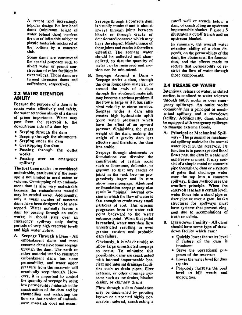
2.3 WATER RETENTIONABIUTYBecause the purpose of a dam is toretain water effectively and safely,the water retention ability of a dam isof prime importance. Water maypass from the reservoir to thedownstream side of a dam by:
• Seeping through the dam• Seeping through the abutments• Seeping under the dam• Overtopping the dam• Passing through the outlet
works• Passing over an emergency
spillway
The fITst three modes are consideredundesirable, particularly if the seeJ>age is not limited in areal extent orvolume. Overtopping of an embankment dam is also very undesirablebecause the embankment materialmay be eroded away. Additionally,only a small number of concretedams have been designed to be overtopped. Water normally leaves adam by passing through an outletworks; it should pass over anemergency spillway only duringperiods of very high reservoir levelsand high water inflow.
A. Seepage Through a Dam - Allembankment dams and mostconcrete dams have some seepagethrough the dam. The earth orother material used to constructembankment dams has somepermeability, and water underpressure from the reservoir willeventually seep through. However, it is important to controlthe quantity of seepage by usinglow permeability materials in theconstruction of the dam and bychannelling and restricting thenow so that erosion of embankment materials does not occur.
Seepage through a concrete damis usually minimal and is almostalways through joints betweenblocks or through cracks ordeteriorated concrete which mayhave developed. Maintenance ofthese joints and cracks is thereforeessential. The seepage watershould be collected and channelized, so that the quantity ofwater can be measured and erosion Can be minimized.
B. Seepage Around a Dam Seepage under a dam, throughthe dam foundation material, oraround the ends of a damthrough the abutment materialsmay become a serious problem ifthe flow is large or if it has sufficient velocity to cause erosion.Seepage under a dam alsocreates high hydrostatic uplift(pore water) pressures whichhave the effect of an upwardpressure diminishing the massweight of the dam, making theweight of a gravity dam lesseffective and therefore, the damless stable.Seepage through abutments orfoundations can dissolve theconstituents of certain rockssuch as limestone, dolomite. orgypsum so that any cracks orjoints in the rock become progressively larger aod in tumallow more seepage. Abutmentor foundation seepage may alsoresult -in upipingH internal erosion in which the flow of water isfast enough to erode away smallparticles of soil. This erosionprogresses from the water exitpoint backward to the waterentrance point. When that pointis reached, water may then flowunrestricted resulting in evengreater erosion and probabledam failure.Obviously, it is nol desirable toallow large UTlTestricted seepageto occur. To minimize thispossibility, dams are construcledwith internal impermeable barriers and internal drainage facilities such as drain pipes, filtersystems, or other drainage systems such as toe drains, blanketdrains, or chimney drains.Flow through a dam foundationmay be diminished by groutingknown or suspected highly permeable material, constructing a
culoff wall or trench below adam, or constructing an upstreamimpermeable blanket. Figure 2.5i1hrstrates a cutoff trench and anupstream blanket.In summary, the overall waterreteotion ability of a dam de-pends, on the permeability oflhedam, the abutments, the foundatioli, aod the efforts made toreduce that permeability or restrict the flow of water throughthose components.
2.4 RELEASE OF WATERIntentional release ofwater, as statedearlier, is confmed to water releasesthrough outlet works or over emergency spillways. An outlet workscommonly has a principal or mechanical spillway and a drawdownfacility. Additionally, dams shouldbe equipped with emergency spillwaysto manage extreme floods.
A. Principal or Mechanical Spill'way - The principal or mechanical spillway maintains the normalwater level in the reservoir. Itsfunction is 10 pass expected floodflows past the dam in a safe andnonerosive manner. It may consist of a simple metal or concrete·pipe through the dam or a systemof gates that discharge waterover the top into a concretespillway. Either method uses theoverflow principle. When thero:servoir reaches a certain level,water flows into a stand pipe orriser pipe or over a gate. Intakestructures for spillways musthave systems that prevent clogging due to accumulations oftrash or debris.
B. Drawdown Facility - All damsshould have some type of drawdown facility which can:'
• Quickly lower the water levelif failure of the dam isimminenl
• Serve the operational purposes of the reservoir
• Lower the waterlevel for damrepairs
• Purposely fluctuate the poollevel to Jr.ill weeds andmosquitoes

SANDA: GRAVEL
Figure 2.5 Culoll Trench andUpstream Blanket
The valve regulating the drawdown facility should be on theupstream end of the conduit tominimize the risk to the damposed by a possible internal rupture of the pipe.
C. Emergency Spillway - As thename implies, an emergencyspillway functions during emergency conditions to preventovertopping of a dam. A typicalemergency spiJIway is an excavated channel in earth or rocknear one abutment of a dam. Anemergency spillway should always discharge away from thetoe of a dam. so that erosion ofthe toe will noi occur. Furthermore, the spillway should be
..;.'
constructed in such a mannerthat the spillway itself will notseriously erode when it is in use.Obviously, erosional failure ofthe spillway could be as catastrophic as failure of the damitself. An emergency spillwayshould be sized to convey the socalled "design nood" the rare,large magnitude nood used toestablish design criteria. Thespillways of many existing damsare now considered undersizedbecause standards for the designnood have increased over theyears.
•
7


CHAPTER 3HAZARDS, RISKS, FAILURES
3.0 GENERALDam failures are severe threats to lifeand property and are now beingrecorded and documented muchmore thoroughly than in the pasLRecorded losses have been high. Ufeand property Joss statistics fully justify the need for dam owners to betterunderstand the risks to the publicposed by dams, the kinds of hazardsthat promote these risks, and, generally, the reasons why dams fail.Improving a dam owner's understanding of realistic risks and possible reasons for failure is an essentialfirst step in any overall effort toimprove dam safety and preserve thebenefits of dam ownership.
3.1 HAZARDS AS SOURCESOF RISKDam structure itself can be a sourceof risk due to possible constructionflaws and weaknesses which developbecause of aging. The site immediately surrounding the structure mayalso increase structural risk if thedam is not positioned or anchoredproperly or if excessive reservoirseepage erodes the foundation orabutments.The physical hazards which· cancause dam failure are translated intohigh risks when people or propertyare threatened, and where the highrisks to which Americans are exposedare exacerbated by a number ofimportant factors. For instance, inmost states, people are allowed tosettle below dams in-potential inundation zones, thereby compoundingrisk.Natural hazards such as floods,earthquakes and landslides are alsoimportant contributors to risk. Thesenatural phenomena are considered"hazards" because development hasplaced people and property in theirway. since most natural phenomenaexisted long before mankind esta~
lished patterns of settlement. Failureto adjust to these events has been
9
costly both to dam owners and thepublic in general.Human behavior is another elementof dam failure risk; simple mistakes,operational mismanagemen~ unnecessary oversights or destructiveintent can interact with other hazardsto compound the possibility offailure. Thus, a broad range ofnatural and human hazards existthat, taken separately or in combination, increase the probability of damfailure and injury to people andproperty.The following discussion of some ofthe most significant hazards that leadto public risk illustrates the interrelationship of events that can lead todam failure.
3.1.1 Natural hazards that threaten dams - The most importantnatural hazards threatening damsinclude:• Flooding from high precipitation• Flooding from dam failure• Earthquakes• LandslidesFlooding from high precipilQ!ion Ofthe natural events that can impactdams, floods are the most significanLA noodplain map of the U.S. (Figure3. I) gives some idea of the m'\iorflood-prone areas. Flash noods canhappen anywhere - even on smalldrainages - ·but especially in thewesl Floods are the most frequentand costly natural events that lead todisaster in the U.S. Therefore, floodpotentials must be ·included in riskanalyses for dam failure. Dams aresometimes constructed 10 withstanda probable maximum flood (PMF)assumed to occur on .the upstreamwatershed; this assumed event becomes the basis for the design ofsafety factors built into the dam (e.g.,enhanced structural elements orspillway capacity). However, damsare ollen built in areas whereestimates of the PMF are based onrather short precipitation and runoff·records. As a result, spiUway capacitymay be underestimated.

to
Figure 3.1 Estimated Proportion 01 Land In FloodplaIn
Reprinted from the Journal of Soil.nd W.ttrConservation. September-October 1985.Volume 40. Number S.
Copyright 1985 Soil Conservation Socitty of America 1_' ..I ,~••; """ "O~"'"
l'.;I .1 .... ;.. ' r , ....;~. 1••_ 1~.oIl;l••• )
" ,,-,,\ f
.'
c=J o· , ..,~) .',c=J., ·'.-9mm"-_ ........ v.." ....
Floodingfrom damfailure- When adam fails as a result of a flood, morepeople and property are generallyplaced in jeopardy than duringnatural floods. The Rapid City.South Dakota flood of 1970. which'killed 242 people, caused a damfailure which added significantly tothe loss of life. When a natural floodoccurs near a dam. the probability offailure and loss of life almostalways increases.
l1le sudden surge of water generatedby a dam failure usually exceeds the .maximum flood expected naturally;dam failure inundation zones and100-year floodplains are seldom congruent. The upper portion of an inundation zone abnost. always exceedsthe lOO-year floodplain considerably; therefore. residences andbusinesses that would escape naturalflooding can be at extreme risk fromdam failure flooding. Hence. it isimportant to make residents of thosestructures cognizant of the full risk towhich they are exposed so that theycan respond accordingly.
When one dam fails. the suddensurge of water may well be powerfulenough to destroy another down-
stream dam. compounding the disaster. The potential for such a snowballeffect is great. but the problem mayseem remote to a dam owner who hasnot studied the potential impacts ofupstream dams on his own structure.Upstream dams may seem ·too faraway to be a real threat, but inundation zones and surge crests canextend many miles downstream especially if the reservoir behind thecollapsed dam held a large quantityof water.Earthquakes - Earthquakes are alsosignificant threats to dam safety.Both earthen and concrete dams canbe damaged by grouad motionscaused by seismic activity. Cracks orseepage can develop. leading toimmediate or delayed failure. Damssuch as those in California, locatednear relatively young, active faultsare of particular concern; but dams(especially older concrete and earthenstructures) located where relativelylow-scale seismic events may occurare also at risk. Areas 'of the U.S.where significant seismic risks existare indicated in Figure 3.2. However.recenl detailed seismic analyses haveindicated a much broader area of
seismicity sufficient to dam age darns;the seismic risk is essenthlUy nationwide. Dam owners should be awareof the history of seismic activity intheir' locality and should develop'their dam safely emergency pr~
cedures accordingly.Landslides - Rock slides and landslides may impact dams directly byblocking a spillway or by eroding andweakening abutments. Indirectly. alarge laridslide into a reservoirbehind a dam can cause an overllowwave which will exceed the capacityof the spillway and lead.to failure. Aland (or mud) slide can form anatural dam across a stream whichcan then be overtopped and fail. Intum. failure of such a natural damcould then cause the overtopping of adownstream dam or by itself causedamage equivalent to the failure of ahuman-made dam. In addition. largeincreases in sediment caused by suchevenlS can materially reduce storagecapacity in reservoirs and thusincrease 8 downstream dam~s vulnerability to flooding. Sedimentationcan also damage low-level gates andwater outlels; damaged gates andoutlelS can lead to failure.
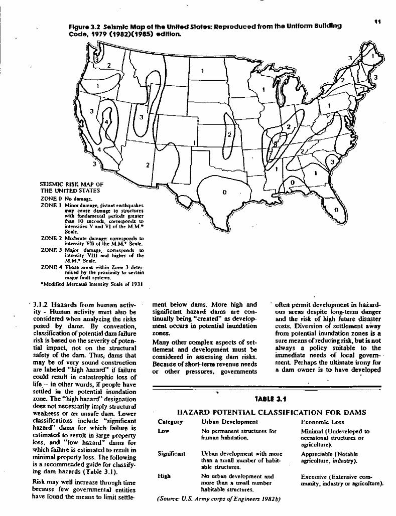
Figure 3.2 SeIsmic Map 0' the Unlled states: Reproduced from the Uniform BuildIngCode, 1979 (1982)(1985) edlllorL
tt
SEISMIC RISK MAP OFTHE UNITED STATESZONE 0 No damage.ZONE I Minor damage, dislanl earthquakes
may cause damage to slrUctureswith fundamental periods greaterthan 10 seconds, conesponds tointensities V and VI or the M.M..Scale.
ZONE 2 Moderate damage: corTt:sponds toint.cnsity V)) or the M.M..· Scale.
ZONE 3 MlUor damage. ronespoods tointensity vln and roper of theM..M.- Scale.
ZONE 4 Those BR:1lS wilhin Zone 3 determined by the proximity to certainmajor r.uh systems.
-Modified Mercalallntensity Scale or 1931
TABLE 3.1
HAZARD POTENTIAL CLASSIFICATION FOR DAMSEconomic Loss
Minimal (Undeveloped 10occasional structures oragriculture).Appreciable (Notableagriculture, industry).
E:l.Ccssive (Extensive community, industry ()£ agriculture).
often permit development in haZardous areas despite Jong-term dangerand the risk or high future disastercosts. Diversion or settlement awayfrom potential inundation zones is asure means orreducing risk, but is notalways a policy suitable to theintmediale needs or local govern-·ment Perhaps the ullimate irony rora dam owner is In have developed
Urban Development
No permanent structures forhuman habitation.
Significant
High
Category
Low
Urban development with morethan a small number of habitable structures.
No urban development andmore than a small numberhabilable structures.
(Sou",,, U.S. Army corps ojEnginu,., 1981b)
•
ment below dams. More high andsignificant hazard dams are continually being "created" as development occurs in potential inundationzones.Many other complell aspects or settlement and development must beconsidered in assessing dam risks.Because ohbart-term revenue needsor other pressures~ governments
3.1.2 Hazards rrom human aclivity - Human activity must also beconsidered when analyzing the risksposed by dams. By convention,classification or potential dam railurerisk is based on the severity orpolential impact, not on the structuralsarety or the dam. Thus, dams thatmay be or very sound constructionare labeled "high hazard" if railurecould resull in catastrophic loss orlire.- in other words, ir people havesettled in the potential inundationrone. The "high hazard" designationdoes not necessarily imply structuralweakness or an unsare dam. Lowerclassifications include "significanlhazard" dams ror which railure isestimated In result in large propertyloss, and "low hazard" dams rorwhich railure is estimated to result inminimal property loss. The rollowingis a recommended guide ror classifying dam hazards (Table 3.1).
Risk may weD increase through timebecause few governmental entitieshave round the means In limit settle-

12 . \
ami implemented a safety programand then to have setUement permitted in the potentia] inundation zoneso that the owner's liability increases.Two extremes of human purpose the wiD to destroy through war orterrorism and the urge 10 develop andto construct - can both result inpublic risks. Dams have proven to beartractive wartime targets, and theymay be tempting to terrorists. On theother hand, a terrorist's advantagefrom holding the public at risk maywell be illusory; the deliberate destruction of a dam is not at all easy tobring about Yet the possibility existsthat such an act could take place, andit should not be discounted by thedam owner.All sorts of other human behaviorshould be included in risk analyses;vandalism for example cannot beexcluded and is in fact. a problemfaced by many dam owners. Vegetatedsurfaces of a dam embankment,mechanical equipment, manholecovers and rock riprap are particularly susceptible to damage bypeople. Every precaution should betaken to limit access to a dam byunauthorized persons and vehicles.Dirt bikes (motorcycles) and fourwheel drive vehicles, in particular,can severely degrade the vegetationon embankments. Worn areas lead toerosion and more serious problems.
Mechanical equipment and associatedcontrol mechanisms should be pr<>.tected from purposeful or inadvertenttampering. Buildings housing mech- .anical equipment should be sturdy.have protected windows, heavy dutydoors, and should be secured withdeadbolt locks or padlocks. Detachable controls. such as handles andwheels, should be removed when notin use and slored inside the padlocked building. Other controls shouldbe secured with locks and heavychains where possible. Manholecovers are often removed and sometimes thrown into reservoirs orspillways by vandals.
Rock used as riprap around dams issometimes thrown into the reservoirs, spillways, stilling basins, pipespillway risers. and elsewhere. Riprap is often displaced by fishermen toform benches. The best way to prevent lhis abuse is to use rock too largeand heavy to move easily or to slushgrout the riprap. Otherwise, the rockmust be regularly replenished and
other damages repaired Regularvisual inspection can easily detectsuch human impacts.Owners should be aware of their re-
- sponsibility for the safety of peopleusing their facility even though theirentry may not be -authorized "NoTrespassing" signs should be posted,and fences and warning signs shouldbe erected around dangerous areas.As discussed in Chapter 10. liabilityinsurance can be purchased to protect the owner in _the event ofaccidents.
3.2 SITE-SPECIFICSTRUCTURAL RISKDeveloping site-specific risk analysesinvolves consideration ofa number ofhazards. Such analyses are helpful instimulating better awareness. planning and design. In some caseS darnstructure analyses are quantitativelybased. and precise conclusions aboutengineering and design can be made.Probabilistic analyses can also beimportant and useful. Still, exactquantitative and probabilistic toolsare not yet applicable in manysituations and do not fully supplement or replace qualitative analyses- informed perception and judgmentof the risks. Judgment and engineering experience should play an important role in reaching useful conclusionsin any site-specific analysis of strue:rurm risk. .
As mentioned in Chapter 2. strucrural risb tend to result from desigoand construction problems related tothe dam materims, construction practice and hydrology. The complexityof the hazard is such that structuraldesign and causes of dam failure aresignificant areas of research inengineering. Indeed belter designcriteria have been developed andsafer dams are being built, but thereis no basis for complacency. Damscontinue to age. people continue tomove into inundation zones andenough hazards exist that the net riskto the public will remain high formany years.
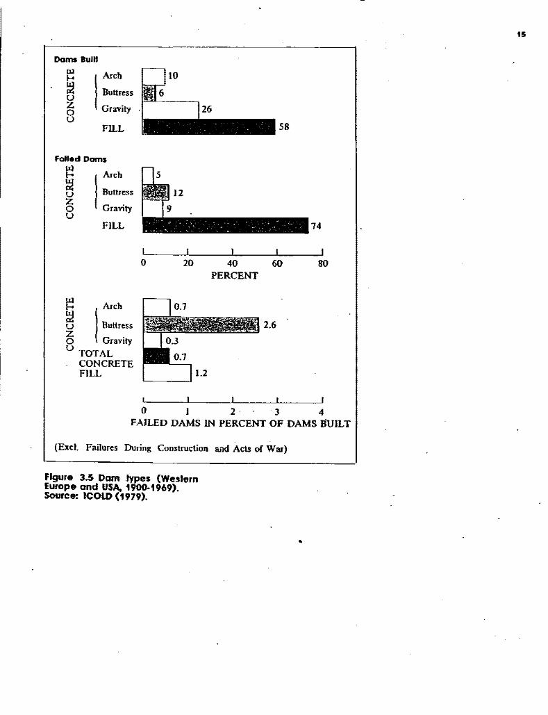
3.3 SOURCES OF DAMFAILUREThere are many complex reasons both structural and nOl}-strucrural for dam failure. Many sources offailure can be traced to decisionsmade during the design and construction process and to inadequate maintenance Of. operational mismanagement.Failures have also resulted from thenarurm hazards already mentioned large scale flooding and earthquakemovement However, from the perspective ofthe owner, the strucrure ofa dam is the starting point for thoroughunderstanding of the potentials forfailure.The International Commission ofLarge Dams (ICOW) conducted asrudy of dam failures and accidents.Figures 3.3 through 3.5 summarizethe data (which pertain only to damsmore than 15 feet high and includeonly failures resulting in waterreleases downstream).
3.3.1 Three categories of struc·rural failure - Three categories ofstructural failure alluded to in Chap-ter 2 are:
• Overtopping by nood• Foundation defects• PipingOvertowing may develop from manysources, but often evolves frominadequate' spillway design. Alternatively even an adequate spillwaymay become clogged with debris. Ineither situation, water pours overother parts of the dam. such as abutments or the dam toe and erosion andfailure follow.Concrete dams are more susceptibleto roundation failure than overtop-ping whereas earthlill darns suffer
. from seepage and piping. However.when overtopping and foundationfailures are lumped together, theyrepresent 82 percent of the failuressrudied by the ICOLD.Figure 3.3 shows the relative importance of these three main categoriesoffailure. Overml, these three eventshave about the same rate of incidence.A more specific analysis of thepotential sources of failure has totake into account types of darns.Similarly. the characteristics of thetype of dam being monitored willpoint to problems requiring morecareful attention by the owner whendeveloping a safety program.

Dam failures 1900-1915 (over 15 m heighl)
Dam failures 1900-1915 (over 15 m heighl)
13
3.3.2 Failures by dam type - Figure3.4 shows the relation between damsbuill and those thaI failed for vanousdam types from 1900 10 1969.Gravity darns appear the safest,followed by arch and nn dams. BUItress darns have Ihe pooresl recordbul are also the ones used least.
Embankment or Ear/1r/i1l Dams The major reason for failure of nu orembankmenl dams was piping orseepage (38 percenl; Figure 3.3).Other hydrologic failures were signmcant, including overtopping anderosion from waler nows. All earthendarns exhibil some seepage; however,as discussed earlier, this seepage canand musl be controlled in velocityand amount. Seepage occurs Ihroughthe structure and, ifuncontrolled, canerode malerial from Ihe downstreamslope or foundation backward lowardthe upstream slope. This "piping"phenomenon can lead 10 a complelefailure of the structure. Piping actioncan be recognized by an increasedseepage now rale, the discharge ofmuddy or discolored waler below Ihedam, sinkholes on or near theembankmenl, and a whirlpool inthe reservoir.Earth dams are particularly susceplible 10 hydrologic failure since moslsediments erode al relatively lowwalerIJow velocilies. Hydrologicfailures result from the uncontrollednow of waler over the dam, aroundthe dam, adjacenllo the dam, and theerosive action of water on the dam'sfoundation. Once erosion has begunduring overtopping, il is almoslimpossible 10 slop. In a very specialcase, a well-vegelaled earth embankment may wilhsland limiled overtopping if waler nows over the lop anddown Ihe face .as an evenly distribuled sheel and does nol becomeconcentrated in a single channel.Table 3.2 lists examples of earthendam f.ilures caused by some ofthese conditions.
•
Overtopping
FILL
Piping~e-
r-Foundation
o
. 138
I 53I-'-----'----------~_ ___J
Overtopping
CONCRETE
Foundation
CONCRmOVERTOPPING
FOUNDATION
PIPING ANDSEEPAGE
OTHERS
100
AU lYPES
OVERl:OPPING 134
FOUNDATION .... 130PIPING AND 1----'------,1r-'28SEEPAGE
OTHERS ~8
o 20 40
PERCENT OF F AlLURES
(excl failures during construction and acts of war)
Figure 3.3 Cause 0' 'allure.Source: ICOLD (1973).
OJ
~
~c;!;,.50gOJ
'"..zOJ
~OJ..
o'--__....L__----'-__--.J
o 10 20 30 0 10 20 30
AGE IN YEARS AGE IN YEARS
(excl. failures during coDStruction and acts of war)
Figure 3.4 Age at 'allure.Source: ICOLD (1973).

,..TABLE 3.2
EXAMPLE OF EARTHEN DAM FAILURES
SOUTHF0RK. PENNSYLVANIAThe famoua Johnatovm diluier, caused by the failure afthe South Fort Dam in 1889 inwhich 2,209 people were tilled, is on eIample of the overtopping of on earthen dam.Heavy rainfall in the upper drainage basin of the dam filled the reservoir and caused overtopping. It was later calculated thaI ifaspillway had betin huih according to specification.and if the original ondel pipes had been available for CuD capacity discharge, there wouldhave heen no overtopping.
TETON DAM, IDAHOThe Teton Dam failure in 1976 was attrihuted to(I) internaleTOsion (piping) of the coreof the dam deep in the righl foundation key trench, with the eroded .oil particles fmWngeIits through channel. in and along the interface ofthe dam with the highly pervious ahutment rock and talus 10 points at the right groin of the dam; (2) destruction of the eIitavenues and their removal by the outrusb ofreservoir waler, (3) the existence ofopeningsthrough inadequately sealed rock joints which may have developed through cracks in thecore zone in the key trench; (4) the development of piping through the main body of thedam that quickly led to complele failure; and (5) the design ofthe dam did _adequatelYtale into account the foundation conditions and the characteristics of the soil used for filling the key treoch.
BALDWIN HILLS AND ST FRANCES DAMS, CAUFORNIATheBaJdwin Hills Dam failed in ]963 following displacement of its foundation. Foundalion problems were ultimately traced to seismic activity along nearby rBults~ The failure ofthe large Sl Francis Dam (part oflbe water supply system for Los Angeles) in 1928 wasalso attributed to a variety of problems reJated to foundation pressures. seepage aroundthe foundation and operation.
(Jansen. 1980).
TABLE 3.3EXAMPLES OF CONCRETE DAM FAILURES
AUSTIN, PENNSYLVANIAAn example of a foundation problem can be found in tbe failure of·the Austin.Pennsylvania Dam in September, 1911. Evidently, the reservoir was f1IJed before theconcrete had set sufficiently. Eventual failure near the base occurred because ofweaknessin the foundation or in the bond 1?etween the foundation and the concrete.
WALNUT GROVE, ARIZONA .In 1890. the Walnut Grove dam on the Hassayompa River failed due to overtopping, tilling ahuut 1SO people. The failure was blamed on inadequate capacity oflbe spillway andpoor construction and workmanship. A spillway 6 X 26 feet had been blasted oul ofrockon onc abutment. but with a drainage area above the dam site of about 500 square miles.the spillway could not provide nearly enough discharge capacity.
(Jansen. 1980)
•
Concrete Dams - Failure ofconcreledams is primarily associaled withfoundation problems. OvertoPPing·i.also a significant cause again primarilywhen spiUways are buill· withinadequate capacity. Other causesinclude failure to leI concrete setproperly, and earthquakes. Theexamples summarized in Table 3.3iIluslrate typical foundation pr0blems leading 10 dam failure.
3.3.3 Age and ils relalion 10failure- Figure 3.5 iUuslrates canseof failure as a function ofa dam's ageat the time of failure. Fotmdationfailures occurred relatively early,while other· causes generaDy tookmucb longer 10 malerialize. Thus, itis not surprising thaI a very large percentage of all dam failures occur during initial fiUing, since this is whendesign or coDStruction naws, or lalentsite defects, appear.
In summary, this outline of thebazards, risks, and failures associated with dams is provided so thaIowners will bave an overview of tbeproblem with which they must deal.Each aspect of a safety programshould be visualized by the damowner in lenns relaled to the mostprobable sources of failure for a particular dam.
FILL
IArch
Buttress
Gravity
FILL
IArch
Buttress
Gravity
Dams Buill
~~UZoU
Failed Dams
~UZou
o 20
58
I I
40 60PERCENT
74
80
15
~ Arch
~ ButtressZ G.o ravltyU TOTAL
CONCRETEFILL
2.6
o I 234FAILED DAMS IN PERCENT OF DAMS IiUILT
(Excl. Failures During Construction and Acts of War)
Figure 3.5 Dam .types (WeslernEurope and USA, 1900·1969).Source: ICOLD (1979).
•


CHAPTER 4DEVELOPING A SAFETY PROGRAM
4.0 OBJECTIVES OF ASAFETY PROGRAMThe significance of the dam failureproblem points out the need for adam safety program Such a programshould be based on an evaluationto determine a dam's structural andoperational safety. The evaluationshould identify problems and recommend either remedial repairs, operational restrictions and modifications",or further analyses and studies todetermine solutions to the problems.A safety program comprises severalcomponents addressing the spectrumof possible actions to be taken overthe short and long term. Theseactions include:
• Assessing the condition of thedam and its components
• Conducting preliminary anddetailed inspections
• Identifying repairs and continuing maintenance needs
• Establishing periodic and continuous monitoring capabilitiesover the long' term
• Establishing an emergencyaction plan to help minimizeadverse impacts should the damfail
• ESlablishing operations pr<>'cedures which recognize damfailure hazards and risks
• - Documenting the' safety program so that Ihe informationestablished is available al timesof need and can be readilyupdaled
Development of a safety programinvolves a phased process beginningwith collection. and review of existinginformation, proceeding to detailedinspections and analyses, and cuI·minaling with formal documentation.Much of the preliminary work can beaccomplished by the dam owner withthe assislance of state and localpublic agencies. However, dependingupon the number and seriousness ofproblems identified by the initialassessmen~ professional assistanceby qualified engineers and conlJac·Iors may be required.
17
4.1 GUIDELINES FORASSESSING EXISTINGCONDITIONSThe guidelines for assessing existingconditions are a sequence of stepsthat will enable a dam owner tosecure the information needed todetermine the need for subsequentdetailed investigations, repairs andmaintenance. The sleps include:
• Reviewing existing data• Visiting the site• Inspecting the dam• Assessing significance of ob-
served conditions• Deciding what to do nextReviewing Existing Data - Theimportant first step is to collect andreview available information on thedam - its design, construction, andoperation. A first requirement is agood map of the site. Maps of thewatershed and the downstream channel reaches are also valuable. Thedesign ofthe dam and its appurtenantstructures should be reviewed toassess its actual performance compared 10 that intended. Engineeringrecords originating during construction should be reviewed to determineif structures were constructed asdesigned. Records of subsequentconstruction modifications should becollected, as well as operation recordswhich document the performance ofthe dam and reservoir. Any previously prepared emergency actionplan should be reviewed to determineif it is up to date and workable. All
- these records should be incorporatedinto a notebook or file; they are mostimportant in establishing a safetyprogram and its supporting documentation. Chapters 5 through Chapter10 provide information to aid thedevelopment ofsuch documentation.It may be, however, that no recordsexist In this instance, a detailedexamination of the structure isappropriate.Visiting Ihe Dam Site - The nextstep is to visit the site. Undoubtedly,the dam site is well known and hasbeen visited numerous times. but inthis visit, there are some particularthings to look for. A fresh look at the

Figure 4.1 Procedural Guidelines lor A Dam Safety Program
and monitoring. The now chart illustrates the cyclical nature of the program and the need for ~ntinuing
vigilance. Emergency actIOn ~an
hopefully be avoided, but a wellthought out plan of action (Chapter8) in case of imminent or actualfailure can greatly reduce damageand loss of life.
4.3 DOCUMENTING THESAFro PROGRAMIt is important to document a safetyprogram in order to make maximum,reliable use of information aboutlhedam. The procedural guidelines thatfollow can serve as an ouUine or tableof contents for a safety programreport. The operations plan (Chapter9) presents a detailed outli,!e of theinformation that should be mcludedin the documentation. The chapterswhich follow suggest forms for
_ inspections, moniioring~ etc. whichcan be used to record information. Itis helpful to maintain all the materi~1in a single notebook or file so that Itcan be updated and available whenneeded. Duplicate copies of much ofthe liIe should be stored at a differentlocation from the original.
v~g...5l;.c:'i!
~
INSPECTION
I ....
~
REPAIRS &.MAINTENANCE
l/,.- ..
•OPERATIONS MONITORING
v
~ ~
EMERGENCYACTION v
4.2 PROCEDURALGUIDEUNES·A SOURCEBOOKThis chapter provides an overview ofbow to establish a safety program.Subsequent chapters detail technicaland procedural steps of the varioussafety program components. Theyinclude:• Detailed Inspection Guidelines
(Chapter 5)• Monitoring and I nstrumenta
tion Guidelines (Chapter 6)• Maintenance Guidelines (Chap
ter 7)• Emergency Action Guidelines
(Chapter 8)• Operations Guidelines (Chap-
ter 9)These program components can bevisualized as a sequence ofinitial andcontinuing 8ctiv~ties to insure damsafety. They are illustrated inFigure 4.1.Again, the program of ~s~ction forboth the initial and conbnumg safetyevaluations establishes the conditionof the dam and provides the base ofinformation necessary for specificactions involving repair, operation,
dam structure and its surroundingsfrom the point of view of its potentialhazard is required
Inspecling the Dam - It will benecessary to take a detailed and sys~
tematic look at all components of thedam and reservoir system. The description of the site's components(Chapter 2) should aid this inspection. The descriptions are generalized,and it must be recogniz.ed that dams.and their components come in variousshapes and sizes and differ greatly indetail. Features to inspect include:
• Access roads and ways• Upstream slope• Crest• Downstream slope• Left and right abutments• Spillways• Outlets and drains• Reservoir area (exposed and
submerged)Conditions to look for range fromobvious deterioration, cracks andslumps, and boiling seepage to notso-obvious internal corrosion andweathering, settlement, and foundation rock deterioration and/or dissolution. A dam may look stable butbe susceptible to failure resultingfrom gradual deterioration of itsinternal structure. Regular and verydetailed inspections (Chapter 5) andfollow-up monitoring (Chapter 6)and maintenance (Chapter 7) areneeded to assure the l)Iaximum levelof safety.Assessing Significance of Observed
. Condilions - Chapter 5 presentsdetailed information on conductinginspections and assessing the signifIcance of observed conditjons. TypicaUy, eroded areas, seepage,. slides.and outflow draw the most attention.Deciding What To Do Next- Theseinitial activities will have provided agood start to establishing a damsafety program. Available information on design and construction of thedam and later structural modifications provides perspective on itsexisting condition relative to thatinlended. Ifno documentation exists,then development of equivalent detailshould be a first priority.Inspection and documentation assistance is available from several sources including state and local agenciesresponsible for dam safety. Pr<>fessional engineering consultants canalso provide detailed inspections,lesting, analyses. and documentation(Chapter 10).

z ~ <.:-0 ;> \11 0
~ 6 ~.... ZZ 0 ~< \11 ~ \11 ~'" ~0 Z 0 \11
'" D! 0
~ ~>- 0 ~'" ti ::c
D! - Cl < ~@....'" '"
~ '" 0 <'" .... 0 < \11
~'" \11 <.: ~~ '" ~"" ~Cl Cl '" ::c '"
TABLE 5.1INSPECTION GUIDEUNES DIRECTORY
CONCRETE DAM (5.4)Upstream FaceDownstream FaceAbutmentsCrests
19
---- JI:---x-- -~--- -----j----t----I-- ---x-- ---}
I r._-'-, ] -,--_- t -t-==1="---- ~ - ,~....:.::t~-=i -:-- ----x -I----t-~ ----i----1- 1------- -;t----- -Jl:------ ---f-----*--l-j--- ---- --
-r--- -I1I--x---*----
'"~o.... g!Z ~
~ ~Z ~
- _. g ~INSPECT FOR -- -< :<
I-I JX x*t--~ t:-~*I~-~t-..: -- --I I}--r-
FEATURE
EMBANKMENT DAM (5.3)Upstream SlopeDownstream SlopeAbutmentsCrestSeepage AreasInternal DrainageRelief Drains
Tabl~ 5.1 lists featurrs '0 b~ inspec'ed 0' adam and 'hI! problems or d(/iciencin to b~
looktd fOT. 11l~ specific sections of thismanual j" which rhl! ",ariousfearurn art discussed art also I-ndica'ed.
SPillWAYS (5.5)Approach ChannelStilling BasinDischarge ChannelControl FeaturesErosion ProtectionSide Slopes
---J f--- ...--- ----
------1;
---oJ t----col-----, ---
INUTS, OUTUTSAND DRAINS (5.6)Inlet & OutletsStilling BasinDischarge ChannelTrashracksEmergency Systems
---- ---- - -t--t--t--- 1-------
GENERAL AREAS (5.7)Reservoir SurfaceShorelineMechanical SystemsElectrical SystemsUpstream WatershedDownstream FIO<Xl-
Plains
--•--- -t----


CHAPTER 5INSPECTION GUIDELINES
5.0 INTRODUCTIONAn effective inspection program isessential for identifying problemsanti providing safe maintenance of adam. An inspection program shouldinvolve three types of inspections:(I) periodic technical inspections;(2) periodic maintenance inspections, and (3) informal observationsby project personnel as they operatethe dam. Technical inspections mustbe performed by specialists familiarwith the design and construction ofdams and should include assessmentsof structure safety. _Maintenanceinspections are perfonned more frequently than technical inspections inorder to detect at an early stage anydevelopments which may be detrimental to the dam. They involveassessing operational capability aswell as structural stability. The thirdtype of inspection is actually a continuing effort by on-site project personnel (dam tenders, powerhouseoperators, maintenance personnel)perfonned in the course of their nOf
mal duties. Education of new personnel is required to assure the continuedeffectiveness of these inspections.
Visual. inspection performed on aregular basis is one of the mosteconomical means a dam owner canuse to assure the safety and long lifeof a dam and its immediate environment. Visual inspection is a straightforward procedure that can be usedby any properly trained person tomake a reaSonably accurate assessment of a dam's condition. Theinspection involves careful examination or the surface and .11 parts of thestructure, including its adjacentenvironment The equipment requiredis not expensiv-e9 and the inspectionusually can be completed in less thanone day.
21
5.1 INSPECTION GUIDELINESTable 5.1 lists dam components andconditions which may be observedduring an inspection. The table summarizes the detailed guidelines presented in subsequent sections ofthis chapter.
Section 5.3 Embankment damsSection 5.4 Concrete damsSection 5.5 SpillwaysSection 5.6 Inlets, outlets and drainsSection 5.1 Other areas
At the end of the chapter, diagramsand tabular listings of the guidelines(Figures 5.3 through 5.6) are presented for the various dam cornponents. The guideline tables providea quick reference to be used inassessing observed conditions9 theirprobable cause and possible consequences9 and remedial actions. Theguidelines also point out theHAZARDOUS problems whereevaluation by an ENGINEER isrequired.The dam owner, by applying themaximum prudent effort, can identifyany changes in previously noted conditions that may indicate a safetyproblem. Quick corrective action toconditions requiring attention willpromote the safety and extend theuseful life of the dam while possiblypreventing costly future repairs.
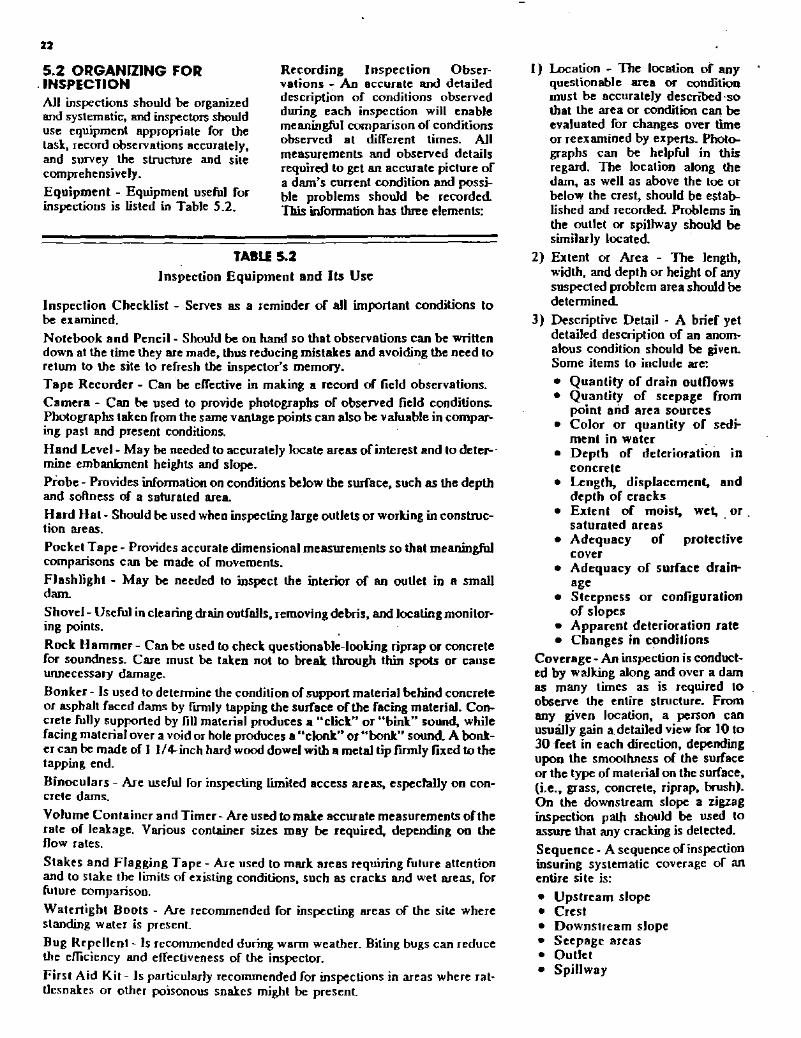
TABLE 5.2Inspection Equipmenl and Its Use
Inspeclion Checklisl - Serves as a reminder of all importanl conditions 10be examined.NOlebook and Pencil- Should be on hand so that observations can be wrillendown at the time they are made, thus reducing mistakes and avoiding the need toreturn to the site to refresh the inspector's memory.Tape Recorder - Can be effective in making a record of field observations.Camera - Can be used to provide photographs of observed field conditions.Photographs taken from the same vantage points can also be valuable in comparing past and present conditions.Hand Level- May be needed to accurately locate areas ofinterest and 10 deter-'mine embankment heights and slope.Probe - Provides information on conditions below the surface, such as the depthand sollness of a saturated area.Hard Hat- Should be used when inspecting large outlets or working in construction aress.
Pocket Tape - Provides accurate dimensional measurements so that meaningfulcomparisons can be made of movements.
Flashlight - May be needed to inspect the interior of an outlet in a smalldam.
Shovel - Useful in clearing drain outfalls, removing debris, and locating monitor-ing points. . .
Rock Hammer - Can be used to check questionable-looking riprap or concretefor soundness. Care must be taken not to break through thin spots or causeunnecessary damage.
Bonker - Is used to determine the condition of support material behind concreteor asphalt faced dams by flIlDly tapping the surface of the facing material. Concrete fully supported by /ill material produces a "click" or "bink" sound, whilefacing material over a void or hole produces a "clonk" or "bonk" sound A bonkercan be made of I I/~inch hard wood dowel with a metal tipfmnly fIXed to thetapping end.
Binoculars - Are useful for inspeeling limited access areas, especially on concrele dams.
Volume Container and Timer- Are used to make accurate measurements oflherate of leakage. Various container sizes may be required, depending on thenow rales.
Stakes and Flagging Tape - Are used to mark areas requiring future attentionand to stake the limits of existing conditions, such as cracks and wet areas, forfuture comparison.
Watertight Boots - Are recommended for inspecting areas of the site wherestanding water is present
Bug Repellent - Is recommended during warm weather. Biting bugs can reducethe efficiency and effectiveness of the inspector.
First Aid Kit- Is particularly recommended for inspections in areas where rattlesnakes or other poisonous snakes might be present
22
5.2 ORGANIZING FOR. INSPECTIONAll inspections should be organizedand systematic, and inspectors shoulduse equipment appropriate for thetask, record observations accurately,and survey the structure and sitecomprehensively.Equipment - Equipment useful forinspections is listed in Table 5.2.
Recording Inspection Observations - An accurate and detaileddescription of conditions observedduring each inspection will enablemeaningful comparison of conditionsobserved at different times. Allmeasurements and observed detailsrequired to get an accurate picture ofa dam's cunent condition and possible problems should be recordedThis information has three elements:
I) Location - The location of anyquestionable area or conditionmust be accurately desenDed'sothat the area or condition can beevaluated for changes over funeor reexamined by experts. Photographs can be helpful in thisregard. The location along thedam, as well as above the toe orbelow the crest, should be estal>lished and recorded Problems inthe outlet or spillway should besimilarly located.
2) Extent or Area - The length,width, and depth or height of anysuspected problem area should bedetermined
3) Descriptive Detail - A brief yetdetailed description of an anomalous condition should be given.Some items to include are:• Quantity of drain outflows• Quantity of seepage from
point arid area sources• Color or quantity of sedi-
ment in water ..• Depth of deterioration in
concrete• Length, displacement, and
depth of cracks• Extenl of moist, wet, or.
saturated areas .• Adequacy of prolective
cover• Adequacy of surface drain
age• Sleepness or configuration
of slopes• Apparent deterioration rate• Changes in conditions
Coverage - An inspection is conducted by walking along and over a damas many times as is required toobserve the entire structure. Fromany given location, a person canusulilly gain a detailed view for 10 to30 reel in each direction, dependingupon the smoothness of the surfaceor the Iype of material on the surface,(i.e., grass, concrete, riprap, brush).On \be downstream slope a zigzaginspection path should be used toassure that any cracking is detected.Sequence - A sequence of inspectioninsuring systematic coverage of anentire site is:
• Upstream slope• Crest• Downstream slope• Seepage areas• Outlet• Spillway

Following a consistent sequencelessens the cbance of an importantcondition being overlooked. Reporting inspection results in the samesequence is recommended to ensureconsistent records. Inspection fonnsare included in Appendix A. Theforms sbould be supplemented withadditional details specifIC 10 a givendam.
Record Keeping - A dated reportshould be filled out for each inspection, and sbould be flied along withany photographs taken (wbich shouldalso be dated). In addition 10 inspection observations, monitoring measurements and weather conditions(especially recent rains, extended dryspells and snow cover) sbould also besystematically recorded and includedin the inspection recordImmediately following an inspection,observations sbould be comparedwith previous records to see if thereare any trends that may indicatedeveloping problems. If a questionable cbange or trend is noted, andfailure is not imminent, a dam ownershould consult a professional engineerexperienced in dam safety. Quickreaction to questionable conditionswill ensure tbe safety and long life ofa dam and possibly prevent cosUyrepairs.
Crucial Inspecrion Times - Thereare at least five special times wben aninspection is recommended regardless of the regular scbedule.I. Prior10 a predictedmajor rainslonn
or beavy snow melt; cbeck spillway, ouUet cbannel, and riprap,
2. During or after a severe rainstonn; cbeck spiJlway, outletcbannel, and riprap,
3. During or following a severewindslorm; cbeck riprap performance during the storm (if possible) and' again after the stormhas subsided,
4. Following an earthquake in thearea; make a complete inspectionimmediately after the event andweekly inspections fot the nextseveral months to detect anydelayed effects,
5. During and inunediately after thefirst reservoir filling; schedule aregular program of frequent cornplete inspections during the perioda reservoir is flISt being filled toassure that design and site condilions are as predicted. In moststates, an inspection and filling
schedule are presenl>ed by thedesign engineer and approved by!be stale engineer.
5.3 EMBANKMENT DAMSAND STRUCTURESEmbankment dams constitute themajority of structures in place in theU.S. Table 5. I presents a generaldirectory of embankment features 10be inspected and the conditions 10look for. The major features include:
• Upstream slope• Downstream slope• Crest• Seepage areasMany of the principles and guidelinespresented in this, section are alsoapplicable to concrete structures.
5.3.1 Upstream Slope - Typically,major problems encountered on anupstream slope are:
• Cracks• Slides• Cave-ins or sink holes
.• Severe erosionThe flISt three conditions may indicate serious problems within theembankment Severe erosion obviously can weaken the structure. Anupstream slope should receive aclose inspection because riprap andbigh water levels can bide problems.(When walking on riprap, cautionsbould be used to avoid personalinjury.) When a reservoir is emptied,the exposed slope should'be thoroughly inspected for - settlement areas,rodent activity, sink boles, or slides.Also, the reservoir basin (bottom ofthe reservoir) should be inspected for
• cave-ins or sink boles.Again,' most importantly, a crisscross path should be used wheninspecting the slope so that cracksand slides can be easily identified. Inmany instances, sighting along thewater line alignment will indicate achange in the uniformity of the slope;an inspector should stand at one endof the dam and sight along the waterline checking for straightness anduniformity. If a crack is seen, thecrest and downstream slope in itsinunediate area should be carefullyinspected.Cracks indicate possible foundationmovement, embanbnent failure, or Ii
surface slide. Locating them can bedi/liculL Cracks can be less than aninch in width, but still several feetdeep. Cracks I foot deep usually are
23
not produced by drying and usuallyare cause for concern. A line ofrecenUy dislodged riprap onimupstream slope could indicate acrack below the riprap.Slides can be almost as difficult todetect as cracks. When a dam is constructed the slopes may not be uniformly graded. Familiarity with theslope coilfiguration at the end of construction can help identify subsequent slope movements. Moreover,the appearance or slides may be sul>Ue; for example, they may produceonly about 2 feet or settlement orbulging in a distance of 100 feet ormore, yet this would still be a signifIcant amount of setUement. Datedphotographs are particularly helpfulin detecting such changes.Sink holes or cave-ins result frominternal erosion of the dam - a veryserious condition for earthen ernbankments. The internal erosion, orpiping, may be reflected by turbidseepage water on exit Surface soilmaterials may be eroded by waveaction, rain runoff, and burrowactivities. IT aUowed to continue, theembankment thickness can be reducedand the structure weakened.
5.3.2 Downstream Slope - Adownstream slope should be inspected carefully because it is the areawhere evidence of developing prol>lems appears most frequently~ Toassure adequate inspection" this areashould be kepi free from obscuringweeds, brush, or trees.When cracks, slides or seepage arenoted in the downstream slope, thedesignated dam safety authoritiesshould be notified inunediately.On the downstream slope, some ofthe more threatening conditions thatcould be identified are: •
~ Cracks• Slides• SeepageCracks can indicate setUement, drying and shrinkage, or the development of a slide. Whatever the cause,cracks should be monitored andchanges in length and width noted.Drying cracks may appear and disappear seasonally and normally will notshow vertical displacement as willsettlement cracks or slide cracks.Slides require inunediale detailedevaluation. Early warning signsinclude a bulge in the embankmentnear the toe of a dam or vertical dis-

placement in the upper portion ofan embankmenLSeepage is discussed separatelybelow.If any of these three conditions areSeen or suspected, the state engineer'soffice should be notified immediately.If a downstream slope is coveredwith heavy brush or vegetation, amore concerted search must bemade.
5.3.3 Crest - A dam's crest usuallyprovides the primary access for inspection and maintenance. Becausesurface water will pond on a crestunless that surface is well maintained,this part of a dam usually requiresperiodic regrading. However, problems found on the crest should not besimply graded over or covered up.When a questionable condition isfound, the state's dam safetyengineers should be notifiedimmediately.
On the crest, some of the morethreatening conditions that may beidentified are:
• Longitudinal cracking• Transverse cracking• Misalignment
Longitudinal cracking can indicatelocalized instability, differential setUement, and/or movement betweenadjacent sections of the embankmenL Longitudinal cracking is typically characterized by a single crackor a close, paraDel system of cracksalong the crest in a direction more orless parallel 10 the axis of the dam.These cracks, which are usually continuous over their length and areusually greater than I foot deep, canbe differentiated from drying crackswhich are usually intermittent, erraticin pattern" sballow, vel}' narrow,and numerous.
Longitudinal cracking may precedevertical displacement as a damaltempts 10 adjust to a position ofgreater stability. Vertical displacements on the crest are usuallyaccompanied by displacements onthe upstream or downstream face ofadam.
Transverse cracking can indicate differential settlement or movement between adjacent segments of a dam.Transverse cracking is usually asingle crack or a close, parallel system of cracks which extend acrossthe crest in a direction more or lessperpendicular to the length of a dam.
This type of cracking is usuallygreater than I foot in depth.Transverse cracking poses a definitethreat to the safety and integrity of adam. If a crack should progress to apoint below the reservoir water surface elevation, seepage could pro~
ress along the crack and through theembankment causing severe erosionand ifnot corrected, leading to failureof the darn.Misaligrunent can indicate relativemovement between adjacent portionsof a dam - generaDy in directionsperpendicular to the axis of the dam.Excessive settlement ofdam materialand/or the foundation can also causemisalignmenl Most problems areusually detectable during close inspection. Misaligrunent may, however, only be detectable by viewing adam from either abutmenL Ifon closeinspection, the crest appears to bestraight forthe length of the structure,alignment can be further checked bystanding away from the dam on eitherabutment and sighting along theupstream and downstream edges ofthe cresL On curved dams, aligrunentcan be checked by standing at eitherend of a short segment of the dam andsighting along the crest's upstreamand downstream edges, noting anycurvature or misaligrunent in thatsection.
5.3.4 Seepage areas - As discussedpreviously, although all dams havesome seepage, seepage in any area onor near a darn can be dangerous, andall seepage should be trealed as apotential problem. Wet areas downstream from dams are not usuallynatural springs, but seepage areas.Seepage must be controlled in bothvelocity and quantity. High velocityflows through a dam can cause progressive erosion and, ultimately,failure. Saturaled areas of an embankment or abutment'can move inmassive slides and thus also leadto failure.
Seepage can emerge anywhere on thedownstream face of a dam, beyondthe toe, or on the downstream abutments at elevations below normalreservoir levels. A potentiaDy dangerous condition exists when seepageappears on the downstream faceabove the toe of a dam. Seepage onthe downstream slope can cause aslide or failure of the darn by internalerosion (piping). Evidence of seepagemay vary from a soft, wet area to a
flowing spring, and may appearinitially as only an area wherevegetation is lush and dark greeri incolor. Cattails" reeds, mosses, andother marsh vegetation often becomeestablished in seepage areas. Downstream abutment areas should alwaysbe inspected closely for signs ofseepage, as should the area ofcontactbetween an embankment and a conduit spillway;drain, or other appurtenant structures and outlets. Slides inthe embankment or an abutment maybe the result of seepage causing soilsaturation and high pore pressures.Since seepage can be present but notreadily visible, an intensive searchshould be made of all downstreamareas where seepage water mightemerge. Even in short grass cover,seepage may not be visible and mustbe walked on to be. found. Ideally, aninspection for seepage should bemade when a reservoir is fuJI.
5.4 CONCRETE DAMS ANDSTRUCTURESFrom a safety standpoint, the principal advantage of concrete darnsover earth dams is their relative freedom from failure by erosion duringovertopping as weD as from embankment slides and piping failures.Although concrete dams comprise aminority of all darns, they are commonly of greater height and storagecapacity than earth structures. Thus,they often represent a potentiallygreater hazard to life and property. Itis important that concrete damownen be aware of the principalmodes of failure of such dams andthat they be able to discern betweenconditions which threaten the safetyof the dam and those which merelyindicate a need for maintenance.Concrete dams fail for reasonS thatare significantly different from earthdams. These include:
• Structural cracks. • Foundation and abutment
weakness• Deterioration due to alkali-
aggregate reaction
Should any of these conditions bediscovered during inspection, anowner should obtain engineeringassistance immediately.
Structural cracks occur when portions of the dam are overstressed andare the result of inadequate design,poor construction or faulty materials.Structural cracks are often irregular,

may run at an angle to the major axesof the dam and may exhibit abruptchanges in direction. These crackscan also have noticeable radial,transverse, or vertical displacemenL
Concrete dams transfer a substantialload to the abutments and foundation. Although the concrete of a dammay endure, the natural abutments orfoundation may crack, crumble, ormove in a massive slide. If thisoccurs, support for the dam is lost,and it fails. hnpending failure of thefoundation or abutments may be difficult to detect because initial movements are often very smaiL
Severe deterioration can result froma chemical reaction between alkalipresent in cements and certain formsof silica present in some aggregales.This chemical reaction producesbyproducts of silica gels which causeexpansion and loss of strength withinconcrete. Alkali reaction is characterized by certain observable conditions such as cracking (usually arandom pattern on a fairly largescale), and by excessive internal andoverall expansion. Additional indications include the presence of agelatinous exudation or whitishamorphous deposits on the surface,and a chalky appearance of freshlyfractured concrete.
The alkali-aggregate reaction takesplace in the presence of water. Surfaces exposed to the elements ordampened by seepage will deterioratemost rapid/yo Once suspected, thecondition can be confirmed by aseries of tests performed- on coresamples drilled from a dam. Althoughthe deterioration is gTadual, alkaliaggregate reaction cannot be economically corrected by ally meansnow known. Continued deteriorationmay require total replacement of astructure.
Inspection of a concrete dam issimilar to that of an earth darn.However, the foUowing additionalitems should be considered:
• Access and safety• Monitoring• Oullet system• Cracks at construction and
expansion joints• Shrinkage cracks• Deterioration due 10 spalling• Minor leakageAccess and safety are importanlbecause the faces of concrete damsare often nearly vertical, and sites are
commonly steeJ>-walled rock canyons. Access to the downstreamface, toe area. and abutments of suchdams may be difficult and requirespecial safety equipment such assafety ropes, or a boatswain's chair.Concrete dams pose a special problem for the dam owner because ofthedifficulty in gaining close accesS tothe steep surfaces. Regular inspection with a pair of powerful binocularscan initially identify areas wherechange is occurring. When thesechanges arc noted, a detailed closeup inspection should be conducted.Oose inspection of the upstream facemay also require a boatswain's chairor a boaL
Monitoring helps detect structuralproblems in concrele dams such ascracks in the dam, abubnents, orfoundation. Cracks may developslowly at first, making it difficult todetermine if they arc widening orotherwise changing overtime. If astructural crack -is discovered, itshould be monitored for changes inwidth, length, and offset, and a monitoring network of instruments shouldbe installed and read on a regularbasis.Outlet system deterioration is a problem for all dams but the frequency ofsuch damage may be higher in concrele dams because of their gTeateraverage hydraulic pressure. Thus,outlet system inspection should beemphasized for large concrete darns.Cracks at construction joints existbecause concrete dams are built insegments, while expansion joints arebuilt into darns to accommodatevolumetric changes which occur inthe structures after concrete placemenL The latter are referred to as..designed" cracks. These joints aretypically constructed so that no bondor reinforcing, except non-bondedwaterstops and dowels, ~xtend acrossthe joints.Shrinkage cracks often occur when,during original construction, irregularities or pockets in the abutmentcontact are filled with concrete andnot allowed to fully cure prior toplacement of adjacent portions of thedam. Subsequent shrinkage of theconcrete may lead to irregular cracking at or Dear the abutmenL
Shrinkage cracks are also caused bytemperature variation. During wintermonths, the upper portion of a dammay become significantly colder than
25
those portions which arc in directcontact with reservoir water. Thistemperature differential can result incracks which extend from the crestfor some distance down each face ofthe darn. These cracks will probablyoccur at CQnstruction or expansionjoints, if these are provided.
Shrinkage cracks can.be a sign thatcertain portions of the dam are notcarrying the design load. In suchcases, the total compression loadmust be carried by a smaller percentage of the structure. It may benecessary to restore load-carryingcapability by gTouting affected areas.This work requires the assistance ofan engineer.
SpaDing is the process by which concrete chips and breaks away as aresult of freezing and thawing.Ahnost every concrete dam in colderclimates experiences continued minordeterioration due to spaDing. Becauseit usually affects only the surface of astructure, it is not ordinarily considered· dangerous. However, if allowed "to continue, spaDing can resultin structural damage, particularly if adam is of thin cross section. Also,repair is necessary when reinforcingsteel becomes exposed. The methodof repair of spalled areas dependsupon the depth of the deterioration.In severe situations, engineeringassistance is required
Minor leakage through concretedarns, although unsightly, is not
-usually dangerous, unless accompanied by structural cracking. Theeffect may be to promote deterioration due to freezing and thawing.However, increases in seepage couldindicate that, through chemical action,materials are £>eing leached from thedam and carried away by the flowingwater. Dam owners should note thatdecreases in seepage could alsooccur as mineral deposits are formedin portions of the seepage channel. Ineither case, the condition is nolinherently dangerous and detailed-study is required before it can bedetennined if repair is necessary forother than cosmetic reasons.

26
5.5 SPILLWAYSAs detailed in Chapter 2, the mainfunction of a spillway is to provide asafe exit for excess water in a reservoir. If a spillway is of inadequatesize, a dam could be overtopped andfail Similarly, defects in a spiDwaycan cause failure by rapid erosion. Aspillway sbould always be kept freeof obstructions, have the ability toresist erosion, and be protected fromdeterioration. Because dams represent a substantial investment andspiUways make up a major part ofdam costs, a conscientious annualmaintenance program should be pursued nol only to protect the publicbut also to riUnimize costs as weD.
The primary problems encounteredwith spillways include:
• Inadequate capacity• Obstructions• Erosion• Deterioration• Cracks• Undermining or spillway ouUetInadequate capacity is delerminedby several factors, such as drainagearea served, magnitude or intensityof storms in the watershed, storagecapacity of the reservoir, and thespeed with which rain waler nowsinto and fills the reservoir. An inadequate spillway can cause the waler ina reservoir to overtop the dam.Obstructions of a spillway may resultfrom excessive groWth of grass andweeds, thick brush, trees, debris, orlandslide deposits. An obstructedspillway can have a substantiallyreduced discharge capacily whichcan lead to overtopping of the dam.Gtass is usuaDy not considered anobstruction; however, tall weeds,brush, and young trees should beperiodically cleared from spillways.Similarly, any substantial amount ofsoil deposited in a spillway whether from sloughing. landslide orsediment transport - should beimmediately removed. Timely removal of large rocks is especiallyimportant, since they can obstructflow and encourage erosion.Erosion of a spillway may occur duroing a large storm when large amountsof water now for many hours. Severedamage of a spillway or. completewash-out can result if the spillwaycannot resist erosion. If a spillway isexcavated out of a rock formation orlined with concrete, erosion is usuallynol a problem. However, if a spillway
is excavated in sandy soil, deteriorated granite, clay. or sih deposits,erosion protection is very important..GeneraJly, resistance to erosion canbe increased ifa spillway channel hasa mild slope, or if it is covered with alayer of grass or riprap with bedding material.A spillway cannot be expected toperform properly if it has deteriorated Examples include: collapse ofside slopes~ riprap~ concrete lining"approach section, the chute channel,the stilling basin, the discharge channel~ or protective grass cover. Theseproblems can cause water to nowunder and around the protectivemateriaJ and lead to severe erosion.Remedial action must be taken assoon as any sign of deterioration hasbeen detected.Drying cracks in an earth spillwaychannel are usually not regarded as afunctional problem. However, missing rocks in a riprap lining can beconsidered a "crackn in the protec~
tive cover, and must be repaired atonce. Cracks in concrete lining of aspillway are commonly encounteredThese cracks may be caused byuneven foundation selUement, shrinkage, slab displacement, or excessiveearth or water pressure. Large crackswill allow water to wash out finematerial below or behind the concrete slab, causing erosion, morecracks, and even severe displacementorthe slab. The slab may even be dislodged and washed away by the now.A severely cracked concrete spillwayshould be examined by and repairedunder the supervision of an engineer.Undermining of a spillway causeserosion at a spillway ouUet, whether itbe a pipe or overUow spillway, is oneof the most common spillway problemS. Severe undermining of the ouUetcan displace sections of pipe, causeslides in the downstream embankment of lhe dam and eventually leadto complete failure of a dam. Watermust be conveyed safely from thereservoir to a point downstream of thedam without endangering the spillwayitself or the embankment. Often thespillway ouUet is adequalely protected for normal now conditions, but notfor extreme nows. It is easy to misestimate the energy and force of nowing water and the resistance of outletmaterial (earth, rock, concrete, etc).The required level of protection is difficult to establish by visual inspectionbut can usually be determined by hy-
draulic calculations performed by aprofessionaJ engineer.
Structures that provide complete erosion control at a spillway ouUet areusually expensive, but often necessary. Less expensive protection canalso be effective, but require extensive periodic maintenance as areas oferosion and deterioration develop.The following four factors, ofteninterrelated, contribute to erosion atthe spillway oullet:J. Flows emerge from the ouUet are
above the stream channel. IfouUet nows emerge at the correctelevation, tailwater in the streamchaimel can absorb a substantialamount or the high velocity, nowand the hydraulic energy will becontained in the stilling basin.
2. Flows emerging from the spillwayare generally free ofsediment andtherefore have substantial sedimentcarrying capacity. In obtainingsediment, moving water will scoursoil material from the channel andleave eroded areas. Such erosionis difficult to design for andrequires protection of the ouUetfor a safe distance downstreamfrom the dam.
3. Flows leaving the ouUet at highvelocity can create negative presSUIeS that can cause material to beloosened and removed from thenoor and walls of the outlet channel. This action is called Ucavita.tion" when it occurs. on concreteor metal surfaces. Venting cansometimes be used to relieve
negative pressures.
4. Water leaking through pipe jointsand/or .nowing along a pipe fromthe reservoir may weaken the soilstructure around the pipe. inadequate compaction adjacent. tosuch structures during construction can compound this problem.
Procedure for inspection - Spillwayinspection is an important part of adam safety program. The basicobjective of spillway inspection is todetect any sign of obstruction, erosion, deterioration, misalignment,or cracking.When inspecting an earth spillway,one should determine whether sideslopes have sloughed, whether thereis excessive vegetation in the channel; and one should look for signs oferosion and rodent activity. Oneshould also use a probe to delenninethe hardness and moislure conlent of

the soil, note the location of particularly wet or soft spots, and see ifthe stilling basin or drop structure isproperly protected with rocks or riprap. Because some erosion is unavoidable during stiJJing. an ownershould also determine whether sucherosion might endanger the embankment itself. If the spillway is installedwith a sill, a dam owner should alsodetermine if there are any cracks ormisalignment in the siJJ and check forerosion beneath or downstream ofthe sill.
Commonly encountered defects ofconcrete spiJIways and general inspection procedures for cracks, spalling. drains, joints, and misalignmentare summarized in the. followingparagraphs.
Hairline cracks are usually harmless.Large cracks should be carefullyinspected and their location, width.length. and orientation noted. Deterioration should be determined andexposure of reinforcing bars shouldbe watched for.
Spillway surfaces exposed to freezethaw cycles often suffer from surfacespaJling. Chemical action, contamination, and unsound aggregatescan also cause spaDing. If spalling isextensive, the spalled area should besketched or photographed. showingthe length, width, and depth of thearea The problem should be examined closely to see if the remainingconcrete has deteriorRted or if reinforcing bars are exposed. The concrete should be tapped with a"honker" or rock hammer to determine if voids exist below the surface.Shallow spalling should be examinedfrom time to time to determine if it isbecoming worse. Deep spaDing shouldbe repaired as soon as possible by anexperienced contractor.
Walls ofspillways are usually equippedwith weep (or drain) holes. Occasionally spillway chute slabs are alsoequipped with weep holes. If all suchholes are dry, the soil behind the wallor below the slab is probably dry. Ifsome holes are draining while othersare dry, the dry holes may be pluggedby mud or mineral deposits. Pluggedweep holes increase the chances forfailure of retaining walls or chuteslabs. The plugged holes should beprobed to determine causes of blockage and soil or deposits cleaned outto restore drainage. If this work is notsuccessful, rehabilitBtion should beperformed as soon as possible under
the supervJSlon of a professionalengineer.Spillway retaining walls and chuteslabs are normally constructed insections. Between adjoining sections.gaps or joints must be tightly sealedwith nexible materials such as tBr.epoxies, or other chemical compounds. Sometimes rubber or plasticdiaphragm materials or copper foilare used to obtain watertightness.During inspection. one should notethe location. length. and depth of anymissing sealant. and probe open gapsto determine if soil behind the wall orbelow the slab has been undermined
Misalignment of spillway retainingwalls or chute slabs may be causedby foundation settlement or earth orwater pressure. The inspector shouldcarefully look at the upstream ordownstream end of a spillway nearthe wall to determine if it has beentipped inward or outward. Relativedisplacement or offset between neighboring sections can be readily identified at joints. The horizontal as wellas vertical displacement should bemeasured A fence on top of theretaining wall is usually erected in astraight line at the time of construction; thus any curve or distortion ofthe fence line may indicate walldeformation.
At the time ofconstruction. the entirespillway chute should form a smoothsurface. Thus, measurement of relative movement between neighboringchute slabs at joints will give a goodindication of slab displacement. Misalignment or displacement of waDs or'.the slab is often accompanied bycracks. A clear description of crackpatterns should be recorded orphotos taken to help in understandingthe nature of the displacement.
27
5.6 INLETS, OUTlETS, ANDDRAINSA dam's inlet and outlet works.including internal drains, are essential to the operation of a dam. Itemsfor inspection and special attentioninclude:
• Reservoir pool levels• Lake drains and internal drains• Corrosion• Trash racks on pipe spillways• CavitationThe topics discussed above forspillways also are relevant.
Reservoir pool levels - Reservoirpool levels are controlled by spiUwaygates, lake drain and release structures, or. nashboards. Flashboardsare sometimes used to permanentlyor temporarily raise the pool level ofwater supply reservoirs. Flashboardsshould not be installed or anowedunless there is sufficient freeboardremaining to safely accommodate adesign nood. Pool level draw downshould not exceed about I foot perweek for slopes composed of clay orsilt materials except in emergencysituations. Very nat slopes or slopeswith free-draining upstream soilscan, however, withstand more rapiddraw down rates. Conditions causingor requiring temporary or permanentadjustment of the pool level include:
• Development of a problem whichrequires that the pool be lowered.Drawdownis a temporary solution until the problem is solved
• Release of water downstream tosupplement stream now duringdry conditions.
• Auctuations in the service area'sdemand for water.
• Repair of boat docks in the winterand growth of aquatic vegetationalong the shoreline.
• Requirements for recreation, hydropower, or water fowl andfish managemenl
Lake drains - A lake drain shouldalways be operable so that the poollevel can be drawn down in case of anemergency or for necessary repair.Lake drain valves or gates that havenot been operated for a long time canpresent a special problem for owners.Hthe valve cannot be closed after it isopened. the impoundment could becompletely drained. An uncontrolledand rapid drawdown could also causemore serious problems such as slidesalong the saturated upstream slope ofthe embankment or downstream

21
nooding. Therefore, when a valve orgate is operaled, II should be Inspected and all appropriate parts lubricated and repaired. It is alsoprudent to advise downstream residents of large and/or prolongeddischarges.
To lest a valve or gate without riskingcomplete drainage, one must physicaUy block the drain inlet upstreamfrom the valve. Some drains havebeen designed with this capabiJiIyand have dual valves or gates, or slotsfor stoplogs (sometimes called bultheads) upstream from the valve.Otherwise, divers can be hired toinspect the drain inlet and may beable to construct a temporary blockat the inleL
Other problems may be encounteredwhen operating a late drain. Sediment can build up and block the draininlet, or debris can enter the valvechamber, hindering its function. Thelikelihood of these problems isgreatly decreased if the valve orgate is operated and maintainedperiodically.
Corrosion - Conosion is a commonproblem of pipe spiUways and otherconduits made ofmetal Exposure tomoisture, acid conditions, or salt willaccelerate corrosion. In particular,acid runoff from strip mine areas willcause rapid corrosion of steel pipes.In such areas, pipes made of n0n
corrosive materials such as concreteor plastic should be used. Metalpipes which have been coated toresist accelerated corrosion are alsoavailable. The coating can be ofepoxy, aluminum, zinc (galvanization), asbestos or mortar. Coatingsapplied to pipes in service aregenerally not very effective becauseof the difficulIy of establishing abond. Similarly, 'bituniinous coatingcarmot be expected to last more thanone to two years on nowways. orcoun;e, corrosion of metal parts ofoperating mechanisms can be effec>tively treated and prevented bykeeping those parts greased and/orpainted
Corrosion can also be conlroUed orarrested by installing cathodic pr0
tection. A metallic anode made out ofa material such as magnesium isburied in the soil and is connected tothe metal pipe by wire. An electricpotential is established which causesthe magnesium to corrode and not thepipe.
Trash on pipe spillways - Manydarns have pipe and riser spillways.As with concrete spillwsys, pipeinlets that become plugged with debris or trash reduce spillway capaciIy.As a result. the potential for overtopping is greatly increased, particularlyif there is only one outleL If a damhas an emergency spillway channel,a plugged principal spiUway willcause more frequent and greater thannormal now in the emergency spillway. Because emergency spiUwaysare generally designed for infrequentnows of short duration, seriousdamage may resuIL For these reasonstrash collectors or racks should beinstaIIed at the inlets 10 pipe spillwaysand late drains.A weIl-designed trasbrack will sloplarge debris that could plug a pipe butallow unrestricted passage of waterand smaller debris. Some of the mosteffective racks have submerged openings which allow water to passbeJ;lCath. the trash into the riser inletas the pool level rises. Openings-thatare too small wiD stop smaU debrissuch as twigs and leaves, which inturn will cause a progression of largeritems to build up, eventually c0m
pletely blockinll the inleL Trasbrackopenings should be at least 6 inchesacross regardless of the pipe size.The larger the principal spiUway conduit. the larger the trasbrack openingshould be. The largest possibleopenings should be used,' up to amaximum of about 2 feeLA trashrack should be properly'attached to the riser inlet and strongenough to withstand the forces offast-nowing debris, heavy debris, andice. If the riser is readily accessible,vandals may throw riprap stone intoiL The size of the trashrack openingsshould not be decreased to preventthis. Instead rock that is larger thanthe trasbrack openings or too Iarge tohandle should be used for riprap.
Maintenance should include periodicchecking of the ract for rusted andbroken sections and repair as needed.The Irasbrack should be checked fr~
quently during and after storms toensure that it is functioning properlyand to remove accumulated debris.
Cavitation - Wheo water nowsthrough an outlet system and passesrestrictions (e. g.., valves), a presswedrop may occur. If localized waterpressures drop below the vapor pressure of water, a partial vacuum is
created and the water actually boils,causing shockwaves which can damage the outlet pipes and controlvalves. This process can be a seriousproblem for large dams where discharge velocities are high.
Testing the outlet system - Allvalves should be fully opened andclosed at least once a year. This notonly limits corrosion buildup on COntrol stems and gate guides, but alsoprovides an opportuniIy to check forsmooth operation of the system.Jerky or erratic operation couldsignal problems, and indicate theneed for more detailed inspection.
The full range of gate settings shouldbe checked. The person performingthe inspection should slowly open thevalve, checking for noise and vibration - certain valve settings mayresuk in greater turbulence. He orshe should also listen for noise whichsounds lite gravel being rapidlytransported through the system. Thissound indicates that cavitation occurrins, and these gate settings should beavoided The operation of all mecbanical and electrical systems, backupelectric motors, power generaton,and power and lighting wiring associated with the outlet should also bechecked.Inspecting the outlet system Accessible portions of the outlet.
.such.as the outfall structure and control, can be easily and regularlyinspected However, severe problems are commonly associated withdeterioration or failure of portions ofthe system which are either buried inthe dam or normally under water.
Areas to be inspected include:
• Outlet pipes 30 inches or greaterin diameter can be inspected internaUy, provided the system has anupstream valve allowing the pipeto be emptied Tapping the c0n
duit interior with a hammer canhelp locate voids behind the pipe.This Iype of inspection sbould beperformed at least once a year.
• Small diameter outlet pipes canbe inspected by remote TVcamera if necessary. The camerais charmeled through the conduitand Iransmits a picture back to anequipment truck. This Iype ofinspection is expensive am usuallyrequires the services of an eogineer. However, if no othermethod of inspection is possible,inspection by TV is recommendedat least once every live years.

• .Outlet intake structures, wetweDs, and outlet pipes with onlydOWllStream valves ore the mostdiJlicult dam appurtenances to
" inspect because they ore usuaUyunder water. These should beinspected whenever Ibe reservoiris drawn down or at fIVe yearintervals. H a defmite problem issuspect.... or if the reservoirremains full over exteoded periods, divers should be hired to per_form an underwater inspection.
5.7 OTHER AREASOther areas requiring inspectioninclude:
• Mechanical and electricalsystems
• Restrvoir surface and shoreline• Upstream watershed• Downstream DoodplainsMecJumical equipment includes spillway gates, sluice gates or valves forlake drains or water supply pipes,stoplogs, sump pumps, Dashboards,retief weDs, emergency power Sources, siphons, and other devices. Allmechauical and associated electricalequipment should be operated atleast once a year and prefera.bly mOreoften. The test should cover the fuJIoperating range of the equipmentunder actual operating conditions.Each operating device should be permanently marked for easy identification, and all operating equipmentshould be kept accessible. All cOntrols should be checked for propersecurity to prevent" vandalism, andfmal1y, all operating instructions'should be checked for clarity andmaintained in a secure, but readilyaccessible location.
•
29
The reservoir surface and shoretineshould be inspected to ideotify poss,ible problems away from the actualstructure. Whirlpools can indicatesubmerged outlets. Large land stidescoming into the reservoir could causewaves overtopping the dam.Floods arise from the upstreamwatershed Therefore, chnracterislicsof the watershed, such as imperviousareas (e.g. parking lots), relate directly to the magnitude of a Dood. Urbandevelopment in a watershed Canincrease the size of Dood peaks andthe volume of runolf, thereby makinga previously acceptable spillwayinadequate. Awareness of upstreamdevelopment and other factors whichmight inDuence reservoir inOows isimportant in order to anticipate p0s
sible problems and necessary ormodifications in the dam.
Development in downstream Ooodplains is also very important to the
"dam owner as the extent of devel-opment and Dood preparedness relatedirectly to loss of life and damagessbould the dam fail.

— blank —

" "GURIS 5.3.1INSPECTION GUIDIUNIS •EMBANKMINT UPSTllIAM $l,OPI
PROBLEM
SINKHOLE
LARGE CRACKS
SLIDE, SLUMP OR SLIP
SCARPS. BENCHES,OVERSTEEP AREAS
PROBABLE CAUSE
Piping or inlemal erosion of embankmenlm.~,rills or foundAlion CIUUS • sinJl.hole.The cave-ill of.." eroded cavern can result in• sink hole, A small hoi, in lh" wall of anoutlet pipe: can deYlllop a sink hole. Ditty......ter 11 tho Cllit indicate! eto.ion of !hIdam.
A portion or th, e:mblnaltlll:nl hal movedbee.IllO o( 1011 of .uonlth, or the found.tionmay hive moved, <:llIIin. embanJun<lnlmovtmanL,
Earth or rocu movl down the .Iop' 1I0nlaJlippll' .lolrl'.c:e becallli ohao a'clp I.lopcl,or the foundation mavil. Alia, look. for.lidt. mov,mtm ill rlll"oir buin.
Wave Iction, locll ..ttJem.nt, or ice IctionCllol.tl $Oil and rock to lrod. and .lide to thelowllr pin of Ule .lope fonninl I bench.
POSSIBLE CONSEQUENCES
HAZARDOUSPipi", can (Imply' reurvoir through. 'maUhole in the wLlI or can Iud La (allure of •dim ... loil pipe, ,rod, throuih th, {oWld...lion or I pCl'YiO\l' pal1 or Lh, dam.
HAZARDOUSlndh:.r.ca on.et or m.ujYll IUdl or 'Ittl..m~n' C:llolKd by foundation faillol....
HAZARDOUSA "rill of IUd" can lead to ob.tructiou ofthe ololtillt or faUun at Lbt dam.
Ero.ion I....nl the width and pouibleheiaht of Ih. embankment .nd could lead toInc:rcucd ..eplp or Ovel1oppln' of tilldam.
RECOMMENDED ACTIONS
Inspect other plru of the dam (or seep,"e ormore ,ink holes. Identify exact CIUSll of sink.hole.. ChllClr. ,,,pllll and l,wlG outtlo..... ,rot dirty Wltlt. A qualifiod '"Piller shouldin.pect the c;ondltlort.l and l'tconvnendfurther action. to be lUen•ENOll'lEER REQUIRED
Depclndinl on embanknumt Involved, dr,wI'CI4lr'Yoir level down. A qulltled engln"rJhould inl~ct the conditionJ and recommend further Ictlan. to be tlkln;ENOll'lEER REQUIRED
Evaluate tl..l-nt or the .lIdL Monitor .Ud.,(See Cbapter 6.) Draw the rllinoif' Itveldown It .&flty of dam I. thttltened. Aqullmed engin.er should in.pelOt the eon·diOon. and rccorNnond further actlon. to betuen.ENGll'IEER REQUIRED
Delennine ..ICt clun of ,cup.. DonlCllU1IY eanllwork, fC,lort; embankmentto orilln.1 slope and provide adequale proteGtlon (beddlnl and I"iprlp), Sot Chlpter7.

" PROBLEM
BROKEN DOWNMISSING RIPRAP
EROSION BEHINDPOORLY GRADED RIPRAP
Flgur•• 5.3.::lnlpectlon Guld.Unn •Downl'r.am $lope
SLIDE/SLOUGH
PROBABLE CAUSE
Poor quaLity riprlp hu deteriorate:d. WI"'.acuon or iell Iction hu dilplacad ripr.p.RoW'ld IIld IimilaNite:d roc:kI have rollllddewoNU.
Similar-.lud rock, allow ..... IVU to pin be-tw.," tham and .rodt small grlvol pll1Jcl'land 'Oil.
."
\.,",
I. Lick or or 10•• or Itrll"1th of embankmanl materiLl.2. Loll or Itrcnlth can be attributed 10Inliltntion of waltir lnl.O!.he embanJunent orlou or support by the roWldatiolt.
POSSIBLE CONSEQUENCES
Wave Icuon '&&1nlllhellll unpltlt.lctlld ....ud.cr..~.. tmbanimC"l width.
Soil J. 'rvdcd .way (rom bclWld the riprlp.nu, Lliowl riprap to ..a1:s. provldin. I...prQl.oGtion and dtcruHd tmbinlmtm. wK1lh.
HAZARDOUSMUlive 'lide cUll lhroua!t crnt or upItream Ilope rcduclnl ","board and CnJU,cetlon. Stnlclutll coUap.. or oyenoppingCIJl re,ull,
RECOMMEND ACTIONS
Ro-."Llbli.h normal Ilope. PI"l1 baddin,and c;;omptltlnt ripr.p. (St. Chapter 7.)
ao-••tablilh ,tracY"1 slope! pltI~cuon.
Place bedc1in. mwriaj, ENGlNEER RE·QUUlED (or d••I&n (or pad,l.Ion and li~.rot l'Ol:i ror btddln& and riprlp. A quaJUltdIn&in'" .hould in,pea the condillons andrttVOmmcnd l\uthor laian. 10 b4l laken,
I. Mea.Ute o,;tcnl Illd dilplaccmenl of.lIdo.2. It continued moyement U seen. bo~n
lowering wal.Or level unal movement SlOps.J. Havel quaJined C1n~cer il'\$pcct the eon·dition and rcconvnend further Iction.ENQINEER REQUIRED

.,PROBLEM
TRANSVERSE CRACKING
CAVE IN/COLLAPSE
LONGITUDINAL CRACKING
SLUMP(LOCALIZED CONDITION)
PROBABLE CAUSE
t>itrlln:ntlal settlement of the cmban&menlalao Iuds to ttlllYerse crackina (e.J., "nterulttlcs morll than Ibutmenul.
I, LIck or adequate comp.euon.2. Rode"' hoi. below.J. Pipinl ttuolllb embankment or foWld.allon.
I. DryitIIII1d altrin.kl&ll of surface maleri,1.2. DoWNllcun movement 0( .,ttl,mentolcmbanim,nL
Preceded by erosion unden::uttins I portionor thll slope. Can &Iso be round on .tlllP,lopu.
POSSIBLE CONSEQUENCES
HAZARDOUSSettl~menl or slvink.lll c,.ck~ un Iud to'UP"11 of rlllll'Voir wiler throush lhll dam.SluiI'lkl'lI crick....Uo.... luter 10 enter theembanJonenL nul promolet .INT.tion andinereuc. (r":r.t·thaw "tion.
HAZARDOUSlIldicllCI. pouibll wub out of embankmcmt.
I. Can be an culy wuninl of I pol.cntialslide.2. Shrinklp crlCU Iilow water to c,"LIlr tnllemblnkment Irld r""Iin, will lw,r «ll'1cklh, ernbankmGlLJ. SettJement or sUde IhowinS 10" orItlellllh in embankment I;an Iud to lLilu,..
Can UpO.tll Impervious zona 10 erolion IDdIud to ful1hu Ilumpll.
RECOMMENDED ACTIONS
I. (f ",ceSl&r)'. plus upstrllm lind of crier.to prevent now. from the rlSlIr'Volr.2. A qutlUled ,n&innT should inspect thecondilton, and 'llconvn,nd l\uthn IcYan,tobe talton.ENGINEER REQUIRED
1. In.peel for and lmmodlatelY rePlIr rodllothollIS. ConlTOl rodenu to preYent fuNredam'I"2. HIYtl .. quaW1lld anJ,in,., in,peel the can·dillon U1d recommlnd further awan,ENGINEER REQUIRED
I. If crac:lu are from d1yinlo dre" ..... withwIII..complc:ted mlLllriaJ to Ir.lllP furflC,wltor oul and nllura! moi.turl in.1., U crlCu UI 'ILenslvl, I qu.lilledenlineer should IlIIptet the condiUolII andrecommend lurther IcLioD' 10 be l&ken.ENGINEER REQUIRED
I. [n.peC! lrea ror seepale.2, Monitor ror progrenivll raJJure.J. Hive I qualified eni!ne,r inspect the condition and retonvnlnd rul1her action.ENGINEER REQVIRED
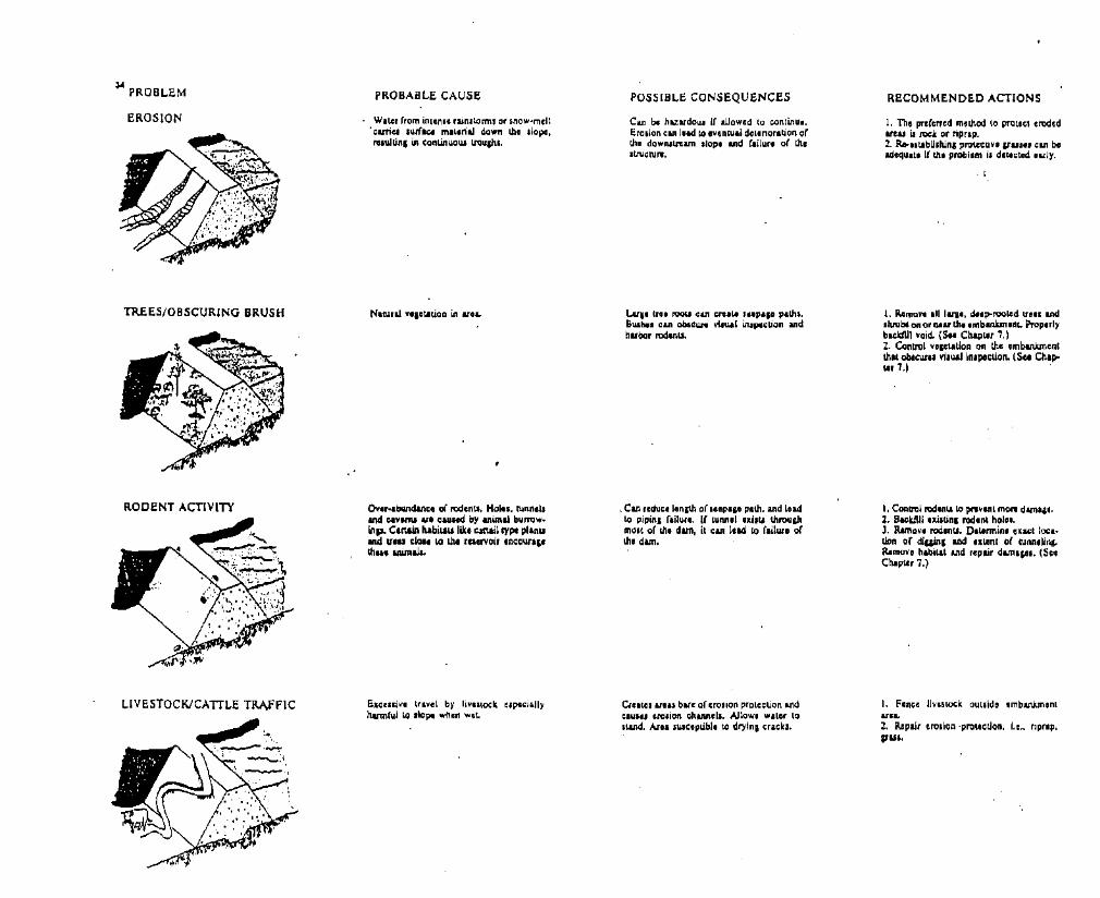
,. PROB~EM
EROSION
TREES/OBSCURING BRUSH
RODENT ACTIVITY
~IVESTOCKICATT~E TRA,fFIC
PROBAB~E CAUSE
Water (rom in'cn•• rainstorms or sno....·melt.curiq .\ufacc maleriaJ down lb., .Iopo.""WUAI in conLinuoUl tnlu&hl.
Ov,r·.bw1d&nIOO of rodenu. Hoi... tl.lnn,1sand elYImi let cau.ed by AnUnal blln'Owinp. Certain IlIbiLaulik, c:att&il trpt pllnlland II." clo.. wLb, fC'Cl'Voir 'OCOurl"th... lnima1l.
EICClljVI travel by livmock 'Ipc<:iallyharmful ~ ,lop' when wcL
POSSIB~E CONSEQUENCES
Can be hUlldoul if allowed 10 continue.Ero,ion can lead 10 eventual dcl,rior,tion oflit. dowrutrum slop. and (lihue of the,weN....
Lule Ir'lI I'OOli can ernUl 't'piSD path•.BUlh•• can obICUAI ri.ual ulIPll:tion andhubor rod.nu.
. Can reduce lenith o{ lI11p.,e P.th. and Iudto pipinl {ailure. I( tUMel Illl.lI throudlmOlt or Ui, d"". it can I",d to rallurl ofthe dam.
Crcalel UIU bue o{ ero.ion prote~tion inaI:IU." erolion channell. AJlowI ......'0' to.\.Ind. Ast. IUlc:opublo to dl')'inll:raclt••
RECOMMENDED ACTIONS
I. The prcr,n,d method to protect erodedare., i.I nx:lr. or "plap.2. Re-'ltabUliung PrQlAlctiYl ,,"u... can baadcqUI,1 il th. problem i. dllectcd urI)'.
I. Remove ,II IUi_, deep-rooled (feu and.twbt on or nut the embankment. Prop"i)'bK1cfU1 void. (S.. ChapLet 1,)2. Contltll VI,ltlUon on the embankmentthat obtaii''' vi.u.alln.poctien. (5,. Chip'"Lor 7.)
I. Cootn3l rodln... itt prwYln, morw dam"l•2. Backll.lI nJ.unl rodent hoili.J. RMnOY, rod,nll. OtLonnin. u.ct loc.·don or diuinl LDd IIllocnt or NM.Iin&.RomeY, habi",t and repair damap•. (5'1Chapter 7,)
I. Fencll lJVll:l~k out.ldo cmbWmentU'L2. R.cpair IIro.ion ·prolllcUon, I.e.. riptep,&lUI,
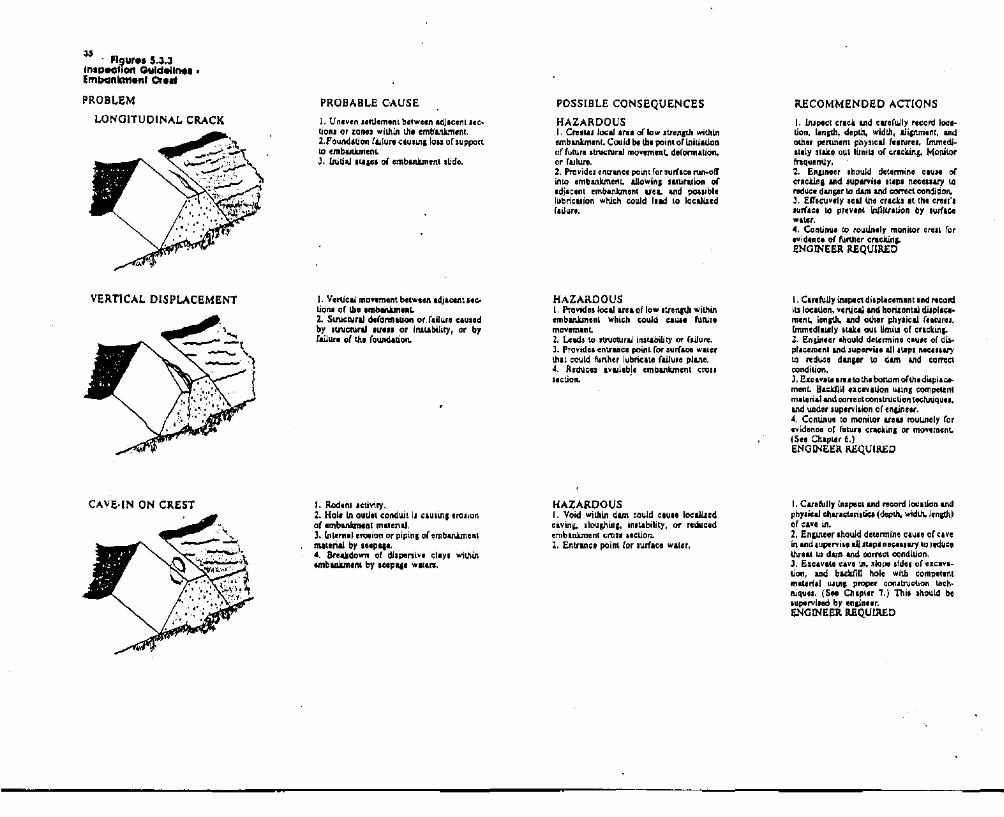
J5 . FI loire. 5.3.3In'I:3-O"O" Guldelln•••Imbclnkmenl ere"
PROBLEM
LONGITUDINAL CRACK
VERTICAL DISPLACEMENT
CAVE·IN ON CREST
PROBABLE CAUSE
I. Uneven .ettlemenl between adjacenl sec_tion. or zones within thl emb'anXmenl.2.Found.l.ion f&.iluOl clusing loIS of supportto embM.nkmenLJ. Initial ILlpl of embankment I~de.
I. v.rtieal mov.ment btlwee" adjlOlnt ,,'"lio"" or Ib, ImblRkm.nL2. Structural ddonnllion or.f.i1urll c:au.edby ItJ'Uc:Nral .tlllI or I",,\lbiliC)', or byfailure of tbl rOWldation.
I. Rodenl activity.2. Hole In outJet conduit i, CIUSInI erosionor .mbanlan.nt malerial,3. Intemal erolion or pipinl of 11mbankmentmaterial by I'lpap.•. Breakdown o( di.penive clay. withinembilWn,nt by J"pl'lII waten:.
POSSIBLE CONSEQUENCES
HAZARDOUSI. CI'llIUS local Ire. of low strength withinembanlunlnt, Could 1M the point of inhi.tionof fuNre stnl<:Nral movement, defonn.tion,or failure.2. Prnvidelentrance point ror surflce run-otl'into Imbankmlnl.. aUowlns Slturl\lion oradja,enl embankment uea. and poaaiblelubril;llion wtti,h r;ould Ilid 10 localizedrailure,
HAZARDOUSI. Provide. 'o;al arll of low .tnn;th withinembankmenl which could elUH IUNr.movem.nL2, Leads to stnlctl.lral lnSl.lbility or fLiJuflI.J. Providll entrance point for surflCe walerthai could further lubricate railure planll.4, R,duc:e~ availlbl. embankment Crollsletion. .
HAZARDOUSI. Void wilbin dam could clu.e localizedclvinio sloughinl, In.l.ability, or reduced11mblnkment croll section.Z, Entranee point Cor aurft!;:o wlter,
RECOMMENDED ACTIONS
I. Insplct crick and carerully record 1001tion. I.nlth. d.pth, widUl, a1icnm.nl, andother peRinllnt physical features. lmmediIlely stake out limiu of cra,king. Monitorfl"equenlJy,2. En~neer should d.tennine elUSI oreTickinl and supemlll sl.p. nllC.llary tore<!u,. danpr to dam and comet condition.J. ElT"tivlly seal the cracks It Ih. ,rest'ssurfac. to prev.nt inllltnrJon by .wiaeewltIlr.4. Continue to routinely monitor crest forevidence or ful'thllr cracitin"ENGINEER REQUIRED
I. Carefully Ul.peetdi.plaeemllnland rer;ordiu location. vertical and neNonlal d.ilplace~
ment, lenath. and other phy,ical rllt\lres,lmmedlately .taltl out Umits of crlckina:.2. Engineer Ihould de"nninCl ClUte of di..placllmenland supervi.. all stop, n.cII.aryto reduce dangllr to dam and cometcondition.J. EXClvate lreato ttl. bottom ofthe dispiacoment. Backfill exclvalion u.inl ,0mpelCnlmil.rial and conectcon.truclion technique I,and under supervision of ,nainnr.4, Continu. to monitor arou routinely rorevidence or fuNre crac:kinl or movement.(See ChaplOr 6.)ENGINEER REQUIRED
I. Car.fully tnspect and record locltion andphysical charlc;t.ori,tie, (deplb. widlh. !enith)of eav. in.2. Enlineor should detllrminll cau.. or Clvein and supervi.. all.t.p. nl"SlIl)' to rtduellthrllt to dam and comet condition.J. Exc.vate eaVll in. slope .id.. of nc.vltion. and baeldlll hole with competontmaLerial u.in, proper con.tr\lction ltch-niques, (S.. Chlpl., 7.) Thi••hould belupervi.ed by enpneer.ENGINEER REQUIRED

"PROBLEM
CREST MISALIGNMENT
LOW AREAIN CREST OF DAM
PROBABLE CAUSE
I. Uney,n movement betwnn .djacent"gmlnu of th, ambankm.nt.2. Ddonnation "'ll.ed by IlnicturaJ .trcUor in.lability.
I. Movlmlnl bltwoon .djacent pans orlb, '''''CNn!.2. Ufllven dtn"tion or dam WIder loadlnlby r"lrvoir.J, Structural "ronnalion or raiJUR nluu •• of mi,allpVnlnt.
I, EXClllivlI ~ottlcmonl in the embanJunentor rOlUldation di",;t1y tanlilb !hili low Ifcain Ib, CA,L2. lDtemaJlm.ion or embankmenl m.llnal.J. POWld,lJon IPreadln, to Up'U'lun indio,down.tRun ditte:tJOfL4. Prolonled wind ero.lon o( Cl'1l.t un.$, lmpropolr f10aJ iJ'1din1 roUowina ;on~
.tN;lJon.
POSSIBLE CONSEQUENCES
HAZARDOUSI. c~ provid. I IMth for "'p'I' throulhthe lImbanluncnt Ctol. nction.2. ProvidN local 're. of low 'b"Clngtn withinembankment, Futur••tNeturaJ moYenta"t.d,ronnauon or f.i1ure could bllin.J. Provide. ,nulIlc. point for .urf", NIlotrlo cnlcr ,mbankm,nL
I, Area of millJ.ipunent i. u.u..Uy .ccompanied by loW uea La cre.t which rtGuI;Ufreeboln1.2. Can produce locaJ ucu allow emblUlk·menl strenilh which may 1.1Ii 10 railure.
~UCCI I'eeboard av.iI.bl. to pUt noodOow, niely throu'" .pillw.y.
RECOMMENDED ACTIONS
I. wpal:t crack U1d IOuefuUy l'lcord eraelr.loc.IIlJgn.lenph, depth, wldUl. and other per!.ina"t physical r...Nt'II'. Stab out limiuof crac:k.ina.2. Enline" should dell.min. UlUC ofc;rIClr.in, &lid luptrvl•• &1I.tep. "_Ciliary '-0~uc. d....aor io dam and eonm condition.J. Exe'YlLt cre.t alonl crick 1.0 I pointbelow the boUom ofUlI go,ell;. Then b.ckliU·Ul' ....c.vnlon LUinl competent m.lArial andIXllT,e:t C(lRltn,ll:;:tion Ilc;hniquCl. Thl. willsaal tho crack .pin.t "'P"I and 'Urf'CIrunoff. (So. Chap'-, 7,) Thl••hould bIsuperviMd by lolin.lr.... Coatlnul to monilor mst routinely (orIvidfnGl or futun!,uack.i.alo (Stl, Ch.pler6.)ENGINEER REQUIRED
I. "Ell.I.bU.h monwnenL1 across crill todetennifll IX&e:t amount. lcx:.tlon. &ndClitenl or mil&IJlMlenL.2. Enlin..r Ihould dlllnnlni nuu of mila.li&MIen~ IIld IUlMrYi'1 all .Iep. nte"....yto r,du;, !.hr,ac 10 dun &nd corrtetcondition.J. Monitor cre.l monwnenL1 on ••chcdulodbui. roUowinl rcmediaJ .;tion to dete;tponiblo "'tur. movlllmlllnL. (SCI Chapler6.)ENGINEER REQUIRED
1, ulIbli,h monwnenu tlonslonS'h of ;flltto deunnin. exact amown. location. Indoxlent of IIttiament in ;fl1L.2. En&int" .hould dOllrmino CIUU or lowuea IlId .upe",bl a.l.l IWpl n,c"luy tol'1lduel pollibll Wilt Of. tA, dun and ~"lCtcoDditJon.J, Ro-ell.l.blith wWonn Cnllt elevltion overcrllt Itnjth by pllC!nl nil In low u .. 1I.1n1proper I;Onttrl.l':uon tocltniqullI. Thl••houidbe IlIptrvl,ed by OIl&1necr.4. Rt-lI.tabu.b monum,nl.l Krotl cml ordam and monll.or RlOnumlinti on , routinobuil to dltlci pouibl. tutu", aolT,l,mtnLENGINEER REQUIRED

" PROBLEM
RODENT ACTIVIIT
GULLY ON CREST
RUTS ALONG CREST
PROBABLE CAUSE
Ne&iec:~ of dam and lack of proper main·lenance proC;:lduru.
I. Poor p'ldlnl X.ad improper drain.se o(CfUI. lmproP4r drain'lI nUllls surflceNnotr to coUect and drlln of cre.t .t lowpoinl in upstream or dOWftlU"1Il1 .houIdu.2. InadeqUlto .pillw.y cap.cily which huclusld dam to avenal'. .
Heavy vehicle tumc without adequltlS orproper maintenance or proper CRlllwf.cInc.
POSSIBLE CONSEQUENCES
I. Obscures larll paN of the dam, prllvent·ln, Idequllcl. IC:a1ratl vl'uII inspection ofall palU of th. dun. Problem. whichthreaten \h. intlpity olth, dam elll developU1d ....m.in undllilcted until thlY prop1l11 to• poinl that WlIllnl tho dam', ,&fllty.2. Ancel.lAd root system. d,vt'lop andpeneltlte inlo the dam', Croll .,won. Whenlhll vllliation dill, the dec,yin, root 1)'5tem. can provide pa\.hl for I.tpap. lbi.rllducll. the etrective 'I,pl,e PIth lhroUlhthe Imbsnkmcnl and could Iud to pOlliblapipinl ,ltua!.ion•.3. PfllfCnU: IUy ace.1I to aU palU rJ thodam for opo...Licn. mUlleinan", andin'pection.4, Providlu habitat fOf rod,nU.
I, Enlrance point for .urfac, 1'\lnolf to enLerdam. Could latur.t.t aetlacent portion. ofthe dam.2. E.pcci.Uy danprou. if hole pcnctr.14.dam belo.... phreatic Unl. Durinl penodJ ofhl5h .Iorlle, .eep'I' p.lb throuih t!le damwould be IP'Cllly reduc:ed and ,pipifll.itu'.tion could develop.
1. C&n reduce i1.ble rn:eboard.2. Reduce. c:ro ection.1 an. 0( dam.J, IMibitl Icce" to all pllU of the crestand dun.4. Can re.ult in a haurdOUI wndilion ifdlloto oYtrtoPPinio'
I. Inhibits ouy 'C~ISU to .11 parts orcrest.2. Allow. continllod developmenl or rolling.J. Allowa lIandin, ""'It" to c:oUect IndnNrlte crllt or dam.4, 0iKrltUllllld m.unlnlnCI ...ehich~1 canlit INck.
RECOMMENDED ACTiONS
I. R.mov. IU damqinl &ftIwth from thldam. nu. wowd lnclw. R1movll of ltOCli.bUlh". bnI./I. mf,n, and P"Owth othorthan 11'11'. Qru••hawd bt oncallupd onIII ugmenu ortho dam to prevent erotion byIUrl.C. runoff'. Rooi .y.lem••hould aI.o beremoved to tJlll mulmum pracucal Cltent,The void which n1lulll (rom removlnl tJloroot sylttm .hould bt backlllled withwellcompettnt, wtll-eomplctld milirili.1. Puture u.nd"irabl, P"QW1.h .hould boremoved b, cutt.lnlor .prayinlo u part of anannual ma&nllauot PfOP'IIT1o ($" Chap.IIr 1.) .J. All cut1Jn1 Of debri. ""ultln&: from thev'lIltaliv, Nmovll .houkl be lmmedl..ttlyt&i.en from th, dam and properly dI.potIed ofoullide thl reslrvoir buin.
I. Complltely bacldliU !,hI hall with QomPll"lent. welkomp.C1od m'lenal.2. lnitato • rodent c:onlrol propam to reducethl bUfTOwitll anlmal population ancIlO preYllnt futu" dam.p to !.he dun. (See Ch.pter7,)
I. RalDro freeboard to dun by Iddin& flUmatlrial in low WI" ulina proper c:on.Wetion IecMiqulII. (Seo Chaplet 7.\2, Rearadin& cresl to provide propc,r drainl;aof SUrflCO ninofl'.J. If IlIlIy was c.lI.ed by OYlrtoppin", provide adeqlllllI spillw.y which meeu curnntdCllp ltandanll. Thl, Ihould be done byengineer.4. Ro-e"lbU.~ pfOlee:tlvo cover,
I, Drain .tAndin, WIlllr rrom NUl.2. RelP'adt and Ncomplcl crest 10 rellor.inlel'ilY and provide propelr dllin.p toIIpltrum slopel. (St. Chapt" 7.)), Provido 11'11111 or ro.dbue mlteri,1 toIccommodltcl tramc.4. Do pcriodlo mainle",",", V1d nuadinlloprevent r,ronnltion or nau. .
------- - ---
.. PROBLEM
PUDDLING ON CI\EST·POOR DP.AINAGE
DRYING CP.ACKS
PROBABLE CAUSE
I. Poor P-adinl and improper drain_go ofQllt.
1. Localiud c:onaoUd.!.ioa or ,cWlm,nl 0110crG.l allow. puOdJCII to dlv,lop.
Material 011 the cr," of d&m IllplJld. &AdcontJ'aetI with al'_maLi wlttia, IUId dryiDlof WuLll.lllr eyeI... Dryjaa c:rac:1u &nI uI"'Uy,bort, Iballow, n&m:IW, ud many.
POSSIBLE CONSEQUENCES
I. C.uu loca!iud 'INt,tion or tha crOlL2, lnhibitJ ACCC" kJ aU putl or lb. damand erul.J, Becom" p~lI"CI.ivcly worn it noloor".;WJ.
Provide. point of entrlllco (or .wfiCI l'Wlotrand surf.ce moilture, CIU.in, oILlNlluon ofad,iIC.ot emblAkment UlU. Thit ll.l1.Uation. and Iller dl'yinlofth. dam. could C'lUlfurther c:rac;lin"
I\ECOMMENDED ACTIONS
I. Drain ,Landin, wIl.Ilr (rom puddlea.2. R.llP'ad. aIId rICQmp.~ cr••t 10 flltor,inllpit)' and provid' proper drain", toupltre&al.1apCI. (5•• Chapler 7.)J. Proyjdli pI"el or roarJbut mmnal toIGCOINIIodat. tr&I1\c:.4. Do period.ic m-tDullw:lCC and rtplcW1' toprl"nt rtronn.Llon of low aRU. .
I. Sui ,wi_ell of <:rlclu wiUl • altll.. impol'·viou. m~rial. (Scle Chapter 7.)2. RouUo.1y pade Cl"llil to Pfovid. properdraJ.aap aDd fill f;n,lu. -OR3. Conr IO",at with non-plutiIO (nol lOllY)m&lClriaJ to pr.vant lUI' moiaNra lOOnt.&D~
variatiolU,

" Flgur•• S.3AInspecllon CiUldeUn•••ImlKlnlnnonl Soopago Noaa
PROBLEM
EXCESSIVE OUANTITYANDIOR MUODY WATEREXITING FROM A POINT
STREAM OF WATEREXITING THROUGH CRACKSNEAR THE CREST .
SEEPAGE WATEREXITING AS A BOILIN THE FOUNDATION
PROBABLE CAUSE
I. Waler hu crealed an open pathway,channel. or pip, lhrou&h thl dam. Th, Wilif
i. ,rodin, and clt1')'in••mbanlcment m.~
terilJ.2. I...&ra. amoWiU o(wllAIr hav" accumulatedin thl down.tream dope. Wiler andemb.nlun-nt mlterial. are llxiting It onepoint. SUlfI'e qltlc.ion may bt !;:autin, th.muddy w,I.I'.J. RDdeoli. (roat leUoo or poor con.lnIctionhave allowed wlter to CAW! aq openpathway or pip' l.brou&h the cmbaakmlat.
1. S,v,,, dryinl nu cauH4 .hrinka,o ormbankmlnl malarial.:z. SeCLI.mtnt In thl embankment or found..lioa il cau.lo. th. trIOIVIII"O Cnlcia.
Som, part of lb. roundation mallrial il ,upplyin,1 now pith. 1'1U, c:ould be clU'od by.,and or plvel I,yer in the fOWld,lion.
POSSIBLE CONSEQUENCES
HAZARDOUSI. Continued now. can uluralAl puu of theembankment Md Icad to ,'idell in th,u ••2. Continued now, can further erodeembllWncnt mlt.eriaJ. and Iud to failure ofthe dam.
HAZARDOUSPlow throu,"" l.ho crack can cause railu... orlho dam.
HAZARDOUSlnl:llIued floWil can lead to ,ra.lon of Ulll(ouod,lion and failure of tho dam.
RECOMMENDED ACTIONS
I. Belin meuurin. ouQ'low quanuty &ndutabliahin. whether wiler i. ,euinl mud-diu••t.lyllI, the nmc. or cilluini up.2. IfquantitY of now i. !.nc::r,ui.n,lhe wlterlevel iQ the relervoir .hawd bllowered \IllUlth' now .tabilizil or slOpt.J. S,U'CiI for opanlnl on up.tI'um 'ld' IDliplUI it pouibl,.4. it. ql,LlliRlld engineer .houJd in.PlC! !.h'Q)ndiuoo and rcwmnlllnd furth,r ae:tJoQl tobe Ukcn.ENGINEER IlEQUlIlED
I. Plu,lb, upltrum .id, oflh, crKk ID 'lopthll now.2. Thll wIlir Illvelin h' re,e""oir 'hould belower,d \lOti! it 11 below the l,v,1 or thecraclu.J. it. ql,Lllifilld ,n;ineer .hould in.pec~, tnllloonditioa and rt;oRUncnd f'ur1ber ac1JORI IDbo lUo" .
I. Examin. \he boil (or ttan.portllion oftoundllioQ material••2. It soli pllUfi:lo. Ill! movin, down'trum,.andba.. or earth .nould be \I11d to crutl •c1ik4I IIOURd the boil: Th, p"'''\Inll cl'lalldby the wlttr l,v,1 within the dike may eon·trol now v,lociUea and lllmporarily pn:vlnlfurther era. ion.J. U 'fOIion i. becominlll'ut,r. the rlllllr·voir l,v,1 .hould be IowIl"ld.4. A ql,LlWl,d ,nlin'" .I\ould Inspect thecondition IIId ",commend fur1bllr aclion. tobe tUliln.ENOINEER IlEQUIIlED
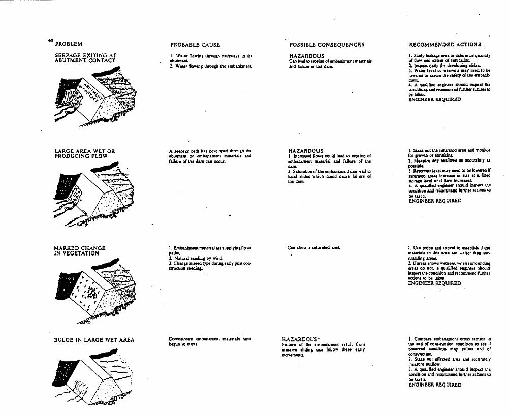
.. PROBLEM
SEEPAGE EXITING ATABUTMENT CONTACT
LARGE AREA WET ORPRODUCING FLOW
MARKED CHANGEIN VEGETATION
BULGE IN LARGE WET AREA
PROBABLE CAUSE
I. W.l.Ir nOW'inl UutJu&b PlthwIY& iD. UlCabuU'ntnl.2. WI"'t nowilll tMlup the C1mblllkmlnl.
A IlICpI'll path hu devGloptd lhroua,h theabutment or Clmbankment m....rial. &nil(ailW1l of the dam CUI occur.
I. Emblllokmea( material UI supplying nowlPIlJu:.z. N.twa! aeediAl by wind.J. CbMlllII ••ed t)1)'I durinl urly poat COQ
struccJ~ .eoc1iA",
Down,tRam embankment mar.cria.l. havebllWI ~ movt.
POSSIBLE CONSEQUENCES
HAZARDOUSCan Iud to Il"Otion ol.mbankmcn~ mll.Criwand flillllo of 1M dam.
HAZARDOUSI. lnereued now. c:ould load to ervaion QfembWm.at mllCrial uxi· (ailuRI of thedam.2. Saturation of the embankment can Iud toloc&.l llidlll wh.i..h l:Ould elUl. failurl ofWI dam.
CLlIo ~how ...tufl~d If'llL
HAZARDOUS'Failurl ot th. Imbankm,n( relult frommu.ivI slidinl ean rouow !hI" Iulymov,manU.
RECOMMENDED ACTIONS
I. Study luka" ..... Lo dl.t.nnin, quantityof now and er.&ln( of IlNraUon.Z. In.PC~ daily (or dt....lopUll .l~•.J. W,14t I.nll" r...rvolr mlY R.ed 10 btlowcrtd to UI\Ilt Ul' .arlty ollh' .mbW....e4. A qualified laii,netr 'bauJd in.pcct !.heoondlUoGl ud recommend~.r I ..donl ~bo ......BNGINBBR REQUIRED
1. Stu.. out !.hI .alutltod un &ad monil,Qr(or gowtb or Ihrinkin&o2. Mtu""'t Ill)' Qu1JlOWt ...C:......,I1IIly IIpOllibl••3. Ruervoi, livol m.y n.ed to tit lowned IflaNratod "1.. iDc;rI..1 in ,b., It I ftud'ICflp Iev.1 0' it flow Ine"I1'"4. It. qu..un,d _,nliA,.r .hould iJuPf~ thecooditio.a IDd ~l:Onun.nd fuM" IIOUoni tobI taicc.BNGINBBR REQUIRED
I. U.. prob, LlIod .hoval to ntlbU,h if lbam&terills in WI .vI' .... W'Ue' than ,u,I'OUAliinI anu.2. UUI...how. w,mln. when lurroWldina:.,111 do not, .. quaUfi,d ,nlin." IhouldIn'ple, tho eondilJon and ftconun,nd l\atIhnactiOnl 10 bI l.Lk,n.~OINBBR REQUIRED
1. Compan lImb.nkm,n( erou nelion tothe ,nd or C'oONiltUction c:ondition (0 '" I(ob.,rvod condition may "flClet C1nd orconall\lGtlon.2. Stlb OUl IiTcelcd &rU and ,"ur.telymaUUrll oull1ow.J. A qu.UO.d ,nain." .hould in.peet !hI!condition 11'111 ~CQnunlnd further aetlon. tobe tAken.BNGINB~R REQUIRED

" PROB~EM
TRAMPO~INE EFFECTIN LARGE SOGGY AREA
~EAKAGE FROM ABUTMENTSBEYOND THE DAM
WET AREA INHORIZONTA~ BAND
LARGE INCREASE IN F~OWOR SEDIMENT INDRAIN OUTfA~~
PROBAB~E CAUSE
I. Waur mavin, rapidly lhroul,h th~
ImbanJunlnt or foundauon i. bam! canltolled or conlain,d by • w,U'llIL1bli,h,dtwf root Iy,tem.
WllA, mavin, tJwuih clieu and auures inthe .bub:lllnl maceriall.
Prolt I.yar or layer ~ .andy mltoriaJ inori&inal c:oaItNCUol\o
A .nortlned "Ipap pith or InCTcued.torap lovII..
POSSIB~ECONSEQUENCES
Condition 3howl ,,"cusive seep'IO in the1Ie1. If conlrol laye' of lurf is destroy,d.rapid erolian of foundation materi.l, could,,,ult in rallul. or the dam.
Can Iud to rapid erosion of _bulmen! andevacuation of tho rlllef\'olr. Can lead lOmu,iVtl sUd" nllt or down.tRam fromtho dam.
HAZARDOUSI. W,tlinl of V1U below lb, area orIxcc'live "Cpl" CUI I,d to IocI1lz.edIn'lablllty or the cmblnkmenL (SUDES)2. EXC4Iujvt I1pwl Clan lead to accel,rated,rollon orembankment mlteril1. and raill.ll'Clof the dam.
HAZARDOUSI. Hlprnk)cicy flow. can causeerOlion ofdrain then emblUmenl mawri,l..2. Can lead to Iliplnl failure.
RE.COMMENDED ACTIONS
I. Carefully inlpect the arn for out!lowquantity and any transported maLfriaJ.2. A qUIUfi,d ,n&ineet .hawd in.peel thocondilion and rKOnvftond l\l.r\b.r le110n. r.obe laken.ENGINEER REQUIRED
I. C....NUy in.PCet. the AtCli to delerminllquantity at now and unount of trwponcdmateriaL2. A qu.Uficd engineer or loololl.t Ihouldlrllpect tbt condition and I1commond ful1herIctionl to bf t&ll.on.
i. Determine u cio..l)' u pouible the nowbeinillrodl.lced.2. U'l1ow lnc:nu", r...rvolr level should 1Mreduced until now ltabillz:e. or .top••J. St&k8 OUI the exact un involved4. Ulinl hand too13. try to idenufy tnemltcri_1 aUowinl the now.,. A qualified enlineer should Lnapecl tnecondition and rocommend li.Irthor aCUOnll.obe l&kln.ENGll'!EER REQUIRED
1. Accurately meuurel outllow quantityand detemlne tnlOWIt or Inonut ovtr prevlOUI now..1. CoU'dJar .UJlplc. to comparo NriJidiry.J. U ,Ithor qUlnulY Of turbidity hulncreulld by 2'%. I qualmod enlinc.,loould evaluate: the condition and; recommend further ac:tion•.ENGINEER REQUIRED

•• "gur•• SAIftipecUon Gulden,... •concr.t. U",tream Slope
PROBLEM
CRACKED DETERIORATEDCONCRETE FACE
CRACKS DUE TO DRYING
Plgur•• S.S'nopeatlon Quld.llnn •Splllw......
EXCESSIVE VEGETATIONOR DEBRIS IN CHANNEL
ip'~.~---...;.
PROBABLE CAUSE
Concratt: downeraLed nliultiD& (rom weathOM" JOLIU lUI., d,wio...1.Od or di.placoed.
n, lClill~•• 11l moi.uul &lid ,hrinlu., uu.~In, ;JacU. NOTE: U.u&!Jy "'0 oa ""IlAd downauum .loplilTlOluy.
AexwnuJ.don of .lidc mltarial., dead Irec.,".:....ive vcptlLivo pvW\h, ou::.,la .piUw.y~&Mol.
POSSIBLE CONSEQUENCES
Soil Is "oded bllWld tM (aca andcavems canbe fonnld. URiUpporttd HcUOGJ of COR".t,criCk. I... ""00 may w.pl,'" conc"'••
Heavy rlias can fill up crlC:U and caUlIsmall paN d f.ft'IbaAlua.Df. ~ move a10nlinUimaJ ,Up IU"""
Raduced di.lOhllle capacity: overllo..... of.pillway; ovenoppinl of dun. Prolon&cdQVOItOpPUl& <:ID ,.WI faiJW't of thll dll11.
RECOMMENDED ACTIONS
Oct'nnw_ c......e. Either pateh with ~Ul orcontld ,nliA'., (or plnnanlnt r"Palrmethod.2. U daml,1 1a u.a.osl"I, I qu&JiIlcdftIPn"r should Wptct u.. CQnditJol1l I.lIdraGCImmand Cwtb., action. 10 be lLUn.ENOINEER REQUIRED
1. MoDilor c:r.cu rOt UIl.rau.. la widl.h.dtpth" or le"ath,1. A qualllled ,nliDeer .hawd In.pect thoconditio. uad n1commlnd li.arth., KUon. 10be t&Un.ENOINEER REQUIRED
Clean out debris pariod.ically: contn:ll veleLldve ifOwUI in spillw.)' channel. wtaU 101boom ia (ront ot .piU......)' entnnlOO to interlOIlpt d.bli••

... PROBLEM
EROSION CHANNELS
EXCESSIVE EROSIONIN EARTH· SLIDE CAUSESCONCENTRATED FLOWS
END OF SPILLWAY CHUTEUNDERCUT
WALL DISPLACEMENT
PROBABLE CAUSE
Surflce runolT from intl"u r&inltomu orflow from .pill....y camn ,unlel materialdown lb' .lopel. r.,ultin, In t;Ontinou.tlOU~. Uv,nocK traffic: Cl"1114 ilolllie.where now coocentrlt.. vari,a.
O!u:hUII velocity too hi~ bottom and.Iopt mlLiriai 100•• or delerionlOd.; c:hlW'leland ba.a.k ,Iopl' too steep; bill .ouunprotected: poor con.sltUalon protlc:tivi,wfac:e: rliJed.
Poor wnftl\lratioD of luUin. buiD unI-UIhIY ,rol1.ible maltrill•• Abacn" of ~totrwill I' 'Dd of c:huLi.
Poor workman.hip; WIG""" settlement offoundation:: Ixc.uive ..nh and ""Iter preaIlIre: in'lIIfIcent .teel bu rtlnforeement ofconer,t•.
POSSIBLE CONSEQUENCES
Unabated erosion c&l1lud to .Udes. ,lump.or ,lip.....hlch can mull in nsdUl:ld .piUwl)'clpacity. bladequ&lI .pillwlY cipacity canIud to embankmenl oveMppinlllld ,Clultin dun f&ilunl.
Di.turbed now plnem; lou of material.inCTllulld ,oditrulnt load down.trnm; col·I.!»e of banJu; failure of .piUwlY: can leadto r.pid .v.eu.tion of the rtlervoir lhroudJlb, $,v,~ly eroded .pi!Jway.
HAZARDOUSSlJ\Icturll damal' to spiUway structure;ooUapat of .l.b and wall Iud to coltl)'l"fPalr,
Minor dilplacemGnt wiJl crllte eddin .ndtw"bulcnce in the now, cIII,inl oro.ion of lbesoil b,lUnd the will. Major di,placement wiUcause .evtre criCks ud ",n\\l11 fallure 0(th' .lJ\IeNIlJ.
RECOMMENDED ACTIONS
PhOIOPlph condition. Repair dam'led"'au by repllcln. ,rod'd malerial withcomplcted nu. Protect. UfU llain.t fUNr,ero.ion by In.lJJlln, Iuilabl, nx:k riprap,R.cveletlll!lll1la it Ipproprlalo. BM' eondj.tion to tho attention of th, ongln"r dUM,nut Irupee:tJon.
Minimizo now vGlo<:it)' by proper design.Un lOund malonal. Keep ehannellUld blnlr;slopel mild. Encour.ge p;rowth of IVU. on.oil surface. Con.lnIct smooth and weU.completed surfKtI. Prolect .urfael' withnprlp, uphall, or eonerele. Rlpair erodedpart \Yin••ound eon.lJ\Ieuon praf;.Liect.
Dew.wr aft'ee~d area: clean out eroded 1111IUld properly b.cklUl. Improve aueam chan.n,1 below chUte'. provld, properly Ilud rip...p ia .ti!lln. buia un. wu.u eutot!'wall.
Rlcon.truction .hould be dono lecordina: tosound onlinoorinl practico., Poundationshould bt cUllfully pRplflld. Adequllllweep hoi.. Ihould be In.talled to relievow.ter proUUfG bclhlnd waU. U" enoushr.infon:llm.nt In the eoncreta. Anchor WillI
to provenl furtner diaplacement" ',lnst.UslnlU between spillway wllb II ncedod.Clean out and b.ckllush drains 10 luurtlproper op"llion.. Con.ull All en&lnellrbefore Iclion. are taken.~NGIN~~R REQUIRED
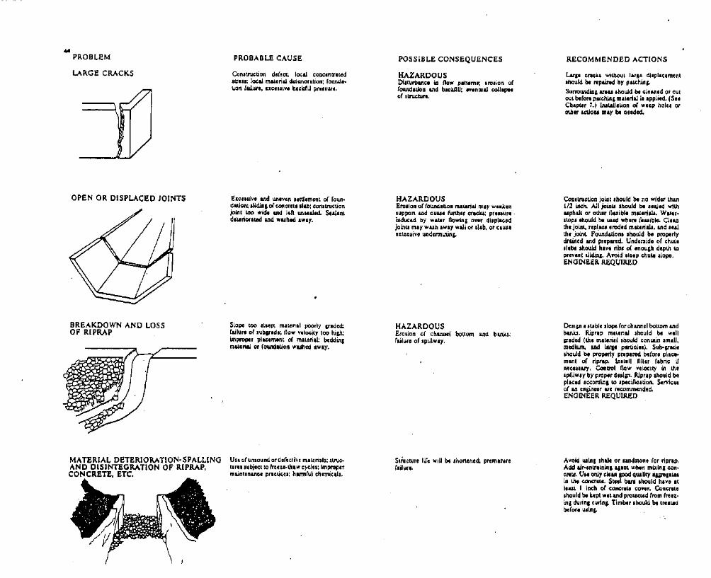
..PROBLEM
LARGE CRACKS
OPEN OR DISPLACED JOINTS
BREAKDOWN AND LOSSOF RIPRAP
MATERIAL DETERIORATlON·SPALLINGAND DISINTEGRATION OF RIPRAP,CONCRETE. ETC.
PROBABLE CAUSE
Con.truction deface local cQI:lI;,ntr.t.edItt...; local mit.';'" delerior,tion; (ound,·\.ion failure. lllic.uiv. bl,kIIU pliny".
E:tcII.lvl and un,ven lattl,mcnt of foun.dation; .Iklinl of concret, ,I&b; con.tnIctionjolllt too wid. and 11ft WII.al.d. StaJanld'lAriOl"ced and wuh,d 'w:.y.
Slope too Iteep; melenal poorly Indectfailurt of Illbpad.: flow vel~ity too high:improper pllcoment of mlLllnll; bcddin;m....rial Of foundation wuhcd ,wly.
Un of unsound or defcl:livi materials; SlNc;.tur...ubjeC:l to frun-th.w c~cllll: ImpropermainlenlRGI pnCUetOJi harmful l:h.miub.
POSSIBLE CONSEQUENCES
HAZARDOUSOi.tUrbUlc, La flow plt1clm.; crosion of(OllAdatioa Illd blclUIU; noontuaJ COUI",'of ,tnu;tu....
HAZARDOUSEro.ion o( (ound.tion malarial may Wluen,uppen ud CIILI' further craW: p,..aur•.induced by wlter flowS over di.pl",djOLnU may \IIuh Iway wall or .llb, or ClU"u;tca.ivo u.adcnninitl"
HAZARDOUSErolion of l:h&Mcl bottom and bank.,;railura of IpillwlY.
Strul:ture life will bI Jhonenect prematuref.ilwe.
RECOMMENDED ACTIONS
Lull cl'lck. wil.houl IUICI dl.plac,mcnt.hould br n1paind by patchin"
Surroundial &rIU .bauld ~ IOlunld or cutoul breCOnl pll.clUna mal.rlal i. applied.. (S"Cbapw, 7,) lnIl.IJJ'l.ion of weep holel oroUi., ""ca. any til a,eded.
Coa.tnll:tlon john .hould blI no wider r.han1/2 Inch. AU JOlall .hould bI ..&I.d withuphill or othlr Oexibl. matlnab. W.ler.'lopt ,liquid hi uaed where (Iuibl.. Clul1the joint. relJl.1CI uod,d mat4rial', &lid tealthe joinL found&lion' 'hould be properlydriUncd and prcplRd. Undllnidc of l:hllLt,I'ba Ihould h". ribe of cnoll&n dcplh 1.0prennt IUlIin" Avoid It,cp c:hu" slope.ENGINEER REQUIRED
Oesilll • subia slope for l:hlMel bottom &lidbanlt. Ripr.p mltlrial should be well&TIded (th, mittNI should l:onWn smlU.mccilwn, and lar,. pWCIII). Sub-gad.'hould be proptrlt ptlpared befora pllC:omen1 or ripr,P. lnmll llI\er fabric; ifne""ary. Control now velocity in !ha,plllw.y by proper dt,liM. Ripr.p ,hould bopl.c:cd Ie<:Ordin. 10 ,pocillcauon. Scrvic:..o( lUI cnlinc., lie rel:Ommcnded.ENGINEER REQUIRED
Avoid win; shalo or ,&Pd.tonc for riprap,Add alr.entrllnln. lalnt wh," mixlo; can·l:I'tle. U.. oNY l:M:an aood qlllUty 'iif1lllttain the concrete. Ste.1 bll1 ahould have .tloaM I ilK:h 01 c:onetlw l:OVoc. ConlilcllUe.hould be kopt w,t and prottl;1&d (rom fra,;·ina dunnll:urin" Tlmblc .hould bot trllttdbofore u.ln" '

POOR SURFACE DRAINAGE
CONCRETE EROSION,ABRASION, AND PRACTURING
LEAKAGE IN OR AROUNDSPILLWAY
TOO MUCH LEAKAGE FROMSPILLWAY UNDER DRAINS
PROBABLE CAUSE
No weep hole.: no drainlP facility; pluUClddrain••
Plow velocity too hilll (uluilly OCCUl"I IIlower ilInd of c:huta In llJih dam.);'. rollinl orpnel and roclu down !.he chull: cavitybehind or billow c:oncrlte .llb.
I. Cr.~1u and joinu: In IlIIololic: (onnauon ItIpillwlY an pcnnitUn, IIlIIpa,I.2. Gr.....1or land lay,,, It IpijlwlY aro pcr·m.iCUnII..P·..•
Drain or cutoff may havtl failed.
POSSIBLE CONSEQUENCES
Wet r~und.tion.hu lower JUpportina capacity: uplift prellUA! relullin, from HIPlPwlter may C.UI. dAmap 10 spillway chute;accumulation of Wile, may abo i"(reu.tolal pnluur. on spillw.y WIU. and CIII,.dam....
Pock maru and spallinl of concrolllsurfaceinay progrelli,ely become wone: small holemay c;aus.. W'ldcnnWnl of foWJdIUon. Iud-inllo fallure of Ilnlc:turl.
HAZARDOUSI. Could I,ad to nc:ouivo 1011 of .laredwater.',2. Could Iud to I progrouive f.lIure itvolocidea are hilh enoup 10 C.UI" erosionof n.tural m'len.".
HAZARDOUSI. EIG...h, now. under Lh••pillway couldIud to ol'Ollon of lOundaLlon mlllri.1 andCOUlPSO of Plru of Lho .plll.lY.2. Uncontrolled now. could lead 10 lou ofllored wlter.
RECOMMENDED AcTIONS
Inllall "'up boln on .pillway waU•• werendortlOl,lhouid bllurrounded and pac:kadwilh II'tded Rllarin, m•.,rial, lnttaU drainIf.tam under ,pillway nlu downJU't1mand. elfin out ,ai.una Wllfp 1101". Blck·nUib Ind nil.bliltace draln 'Y'llIm und., th.supervi.lon of an onsinlle,.ENGINEER REQUIRED
RAimo.... rock. and "'.....Is from .pillwaychutl berMe flood lOuon. Rai•• wlt.r levelin .ullln, buin. UII &oed quality concrotCl,Amari c:onc:nle .urfiCCI II .mooth.ENGINEER REQUIRED
I. Examine exit .rea to sell ir type ormaterial can explain leakage.2. MUlur, now quantiry and chick (or lifOlion or n.tural m.teri.ls,J. Unow rile or amount of IIroded materials"inmues rapidly. roservoir 11'01 should belowClred Wltil now .t.abi1i:tCI Of .lop•.4. A qualified en&ineer should inspect thecoodition and ...commend furthor Iction. tobe lakeR.ENGIN~ER REQUIRED
Sam. u aba'lIl.
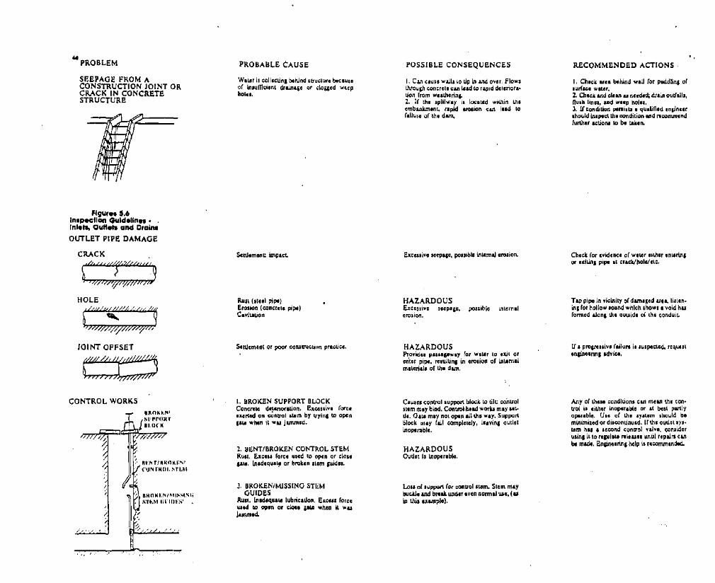
.. PROBLEM
SOOPAGO FROM ACONSTRUCTION JOINT ORCRACK IN CONCRETOSTRUCTURO
fig"," 5.6InlpK.lon Guld.lln... ,Inl.... Oull... and C,alM
OUTLOT PIPE DAMAGE
CRACK
JOINT OFFSET
CONTROL WORKS
UNTJRNOIi.:S r
("UNTMUl. STUI
BHClIi.:NI""~."I.'oriI;
sn;M la'lIn',s'
/
I,' ,
PROBABLE CAUSE
WaLer it collectina bctund Itnlcturll becaunof in.umc;icn~ drainl,e or ,IQUlld weepholn.
Settlement; impact.
Ruu (It.,1 pip')Erolion (cClncrc\O pipe)CaviaLion
Settlement or POO' 1;0nsl;N..:Unn prl",ul;e.
I. BROKEN SUPPORT BLOCKCon",'" detllnortuon. Exccnive fo,,"uel1ed. Oil dJlltrol I\lm by uYinl lO open1'\1 ....h.n it wu jammed.
2. BENT/BROKEN CONTROL STEMRUlt. Ex"" .. (arce used 10 open or clollp ..... lnadequatp or broken Item lIIidn.
J. BROKEN/MISSING STI:MGUIDES
Rull. lrtadtqua.... lubncallon. EllCOI. (orce\lied. to open or ",10.. pta when it w...jllMltd.
POSSIBLE CONSEQUENCES
I. CUI c,un wall,lo tip in and over, flowllhrou&h concrete can lead to rapid deteriora·tion from wulherinio2. I( the .pUlwIY i, locl~d wil.hin theembanJunlnt. rapid tn)I'on can I'ld toraUure or the dam.
Exccuiv, seep,p, pouiblc in\.lmal erosion.
HAZARDOUSExccuive seep'ie, pouiblc Inlemalcrosion,
HAZARDOUSProvidel p.l..p .....y for w.LI, to 'lUt oren'Ir pip'. rnultina in lro.ion or intimalmaterial. of the d&m.
CIIJICI ,0ntrolluppeR block to tile. controlstem m.y bind. Control beld woru rna)' littl•. 0,1.1 may not aPln ,11th, way. Suppol1clock may fa.ll ~mpICltely, llivini outlotinoperable,
HAZARDOUSOutlet Is Inoplrable.
to.. of .upport (or ,ontloillom. Stem mtybu,kJ. and bAlu. under Iven nonnal \lI', (uin UU, ",ampl,).
RECOMMONDED ACTIONS
I. Chick Ula bthind WIU for puddUn, oflunlCa waur.1. eh,ci and clean u nccd~ dr.in OUlllll"flulh linn. and we.p nol...J. 1t conc1itkln penilt.l I qualified cnlin••rIhould in.plc:\ Ih, condition and Bcomm.ndfurthlt acUen. io bI lUln.
Check for ,,,idenelll of wlter either cnlArin,or C:dUnI pi~ It crlck/holG/ctc.
Tap pipe! in vicinity of d&mlled un. Ii. leninC for hollow ,ound ....hlch shaWl I void huformed &lonl lohe Quuide 01 Ihe ..:onduir..
If a provellive failure i. lu.poet.ed, nquuIeniin"nnl advice.
Any of thOlO ",ondltionl can mean the ",ontrol i. eithor inoperablo or It best par\Jyoplrabll!. UIO or tho Iyltem lhould bomlnimi:r.ed or dilcontinuld. If thl outlet 1)'1'l&m has , second concrol valvo. ",onsiderusinl it to regul,1.e releu" until ropurl cantill made. Engine'Rna help il recommlnded.

" PROBLEM
FAILURE OF CONCRETEOUTFALL STRUCTURE
OUTLET RELEASES E'RODINGTOE OF DAM
f&ft?)\~) ;/~VALVE LEAKAGE
DEBRIS STUCK UNDER GATE
.~~.~.>,., ..'1',LOa"":"""//J;),0Jii F
CRACKED GATE LEAF
DAMAGE GATE SEATOR GUIDES
/,. "IRVENT, '/
SEEPAGE WATER EXITINGfROM A POINT ADJACENTTO THE OUTLET
PROBABLE CAUSE
Exceuivi side prelluru aD DOrll'lialo~C1
c:oac;ntl.tnI.;N". Poor CQo"clo quility.
Outlot pipe too .1Iort. Lack or 'D''1J'~dluip.ti.a. pool or .tnIl:CW'W It dcnrmlnun_ of ooadWL
Ice .ction. rult. atrec1 vibraUon. or .tlelSmullinl frons (Cftilll P.ilI l:lwtd wh," i~
.J........
Ru.l., efOlio", cavit.auon, vibr.tioD.' or.ur,
1. A brni in the outlet pipe.2. A p.lJI ror ~ow hu developed alonglJleouuide or the oullet pipe.
POSSIBLE CONSEQUENCES
HAZARDOUSLot:, 01 olltraU .CNcturll upotn ,mowD1WC to .~,iOD by 0l&1I.~ ",11"u,
HAZARDOUSElQ,iw of toe O'lenteepen. downatrcam.Iope, C~Io, propu.i" .Joulhina.
G.~ wiU not clo••. aiLe or Ilom may bedam.1td !II ofron to clo•• plO.
Gate-I'll' maiD (aU l:Omplel.ely. eYKuaUngrtlll'¥Oir.
Leak.g, and 10.. or .upport (or pte leal.Gate may bind ill lLIid.. and becomeInoperable.
HAZARDOUSCOtIanued Ro.... can le.d to raid erosion orembanlunont m.toria1l and railure or thed....
RECOMMENDED ACTIONS
I. Check for prosnui"l (ailWll by monJto....In, typh;:&! dlmllUion, ludl AI "0" ,bawula "gu....2. Repair by patottiAg crub IDd lupplyitllWaUllp vouod concnle .tnICCWli. Tot&.ltlpllQtmloC of ouliall .CIWRU'O maybeD'odod.
I. Eltend pipe t.yond toe (UN' pipe of,amo.WI aDd mal4lnll, aad (orm WllerUl!:llcoa.alction to oz.i,tia, coaduJt).2. Proc.e:t cmbll1bnlDI with ripr.p ovu l\Iit,...blt beddl..ta"
RI.i•• lAd lower ,.to .lowly untJJ debri. i.looIened aad fiolu pale val". When rlll"r.voir 1.1 lowered, ropalr or rwrXlCI tJuhnck.
UII nlYe only in fully 0Pfln or clo.ed po.iLion. Minimize uso OrYalv, unLillea{ can berepa.ir 01 replaced.
Minimize uae o( v.lve until ruidu/'lili canbI repa.ired. IfcaYit&Uon .. the caUII, check1.0 see II' air vent pipe u.i.l, Uld i.unobltNcted.
I. ThomuihlY invlltig.te tha lrea by probIng and/or .hoy,Ulrt,l.o'u if Uta cau.lll:1nbI dewnnlned.2. Odennin. if lukall water I. c:llT'Yinl soilpartiel...J. Determine quantity of flo"'.•. If now increull. or I. clJTYin; embankment materials, tllCl'¥Oir lev,1 should belowered until leu.p ltop.l.,. A ql!.Ulied engineer should' In.pecl ll1acondition and n1commtnd further ilOtion. tobe taJl.en.ENGINEER REQUIRED

— blank —

49TABLE 6.1INSTRUMENTATION AND MONITORING
GUIDEUNES DIRECTORY
MEANS OFPROBLEMDETECTION
Table 6. J lists ftaturrs to be observed at adam" and the suggesled irutromrnts or observation technique to be used Tht sp«i/ic sttrions ofthis manual whtrr an instrument orobservation technique is disnned arr alsoindicoted.
X
-i!
----- ;;
i
)\,1--,
;
Ii
! ~=-I- I - .
"L,
iI!,
x-~-
IL-1--,
X
J--i
I
I_fii
__I
iIj--r-
1-j
J
J--,___ I
--){- X,---x
i - -
Ir
X-1-_
-I-J' --- L!-
~--- 1-
j
-- ;
- f-
I
-- X
x
-T ]-1 --
I I I! 1--- I X -- -X ~ _ Jt. X - --I'f- ;(-- I i X--!
t+F+=l~F-lI ' I !
~ -j I X J J ,(i ,c- -*--- X--XX I 1--- x--Ji:! Jf X X X
-- I ~
1---
X-
lXX
JfX
I,-----
II
x-I,
I
•X
J,I
1-
XII.I
1
I*XXXX-t ---II,XX~X
XI
I
II
X--- X
1II
i --
1II
-- *----x-x!
X
-1-
!XX-X-
IX ---
X ---1'~- --x- x
~------I
I
i I
I Ix- *x-- x-x--- -i.--X ---X-
xx-),{-
*XXX
i;
XXXJiX
1 _2-Ix--
I,,
CONCRETE DAMSUpstream SlopeDownstream SlopeLeft/Right AbutmentsCrestInternal Drain. SystemRelier DrainsGalleriesSluiceways/ContrQls
SPIUWAYSApproach ChannelJnleiJoutJet structureStilling BasinDischarge conduiVChannel
Control FeaturesErosion ProtectionSide Slope.
FEATURE
EMBANKMENT DAMUpstream SlopeDownstream SlopeLeft/Right AbutmentsCrestInternal Drainage Sys.Relier DrainsRiprap & Slope
Protection
OUTLETS. DRAINSlnJeVoutJel structureStilling BasinDischarge Ch~elTrashrackJDebris Control _Emergency Systems
GENERAL AREASReservoir SurfaceMechlelect_ systemsShorelineUpstream WatershedDownstream Channel