Embed Size (px)
Citation preview
AN1525Pulse Oximeter Design Using Microchip’s dsPIC® Digital
Signal Controllers (DSCs) and Analog Devices
INTRODUCTION
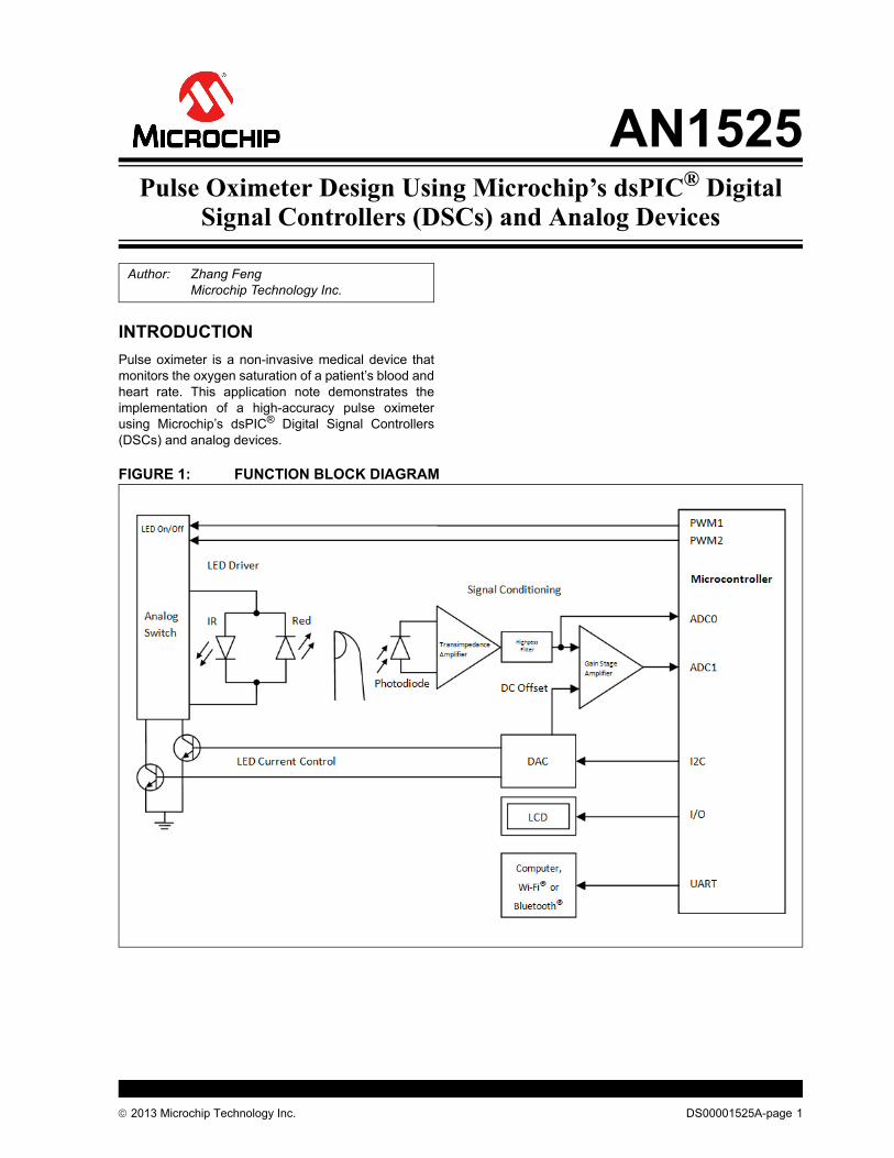
Pulse oximeter is a non-invasive medical device thatmonitors the oxygen saturation of a patient’s blood andheart rate. This application note demonstrates theimplementation of a high-accuracy pulse oximeterusing Microchip’s dsPIC® Digital Signal Controllers(DSCs) and analog devices.
FIGURE 1: FUNCTION BLOCK DIAGRAM
Author: Zhang FengMicrochip Technology Inc.
2013 Microchip Technology Inc. DS00001525A-page 1
AN1525
THEORY OF OPERATION
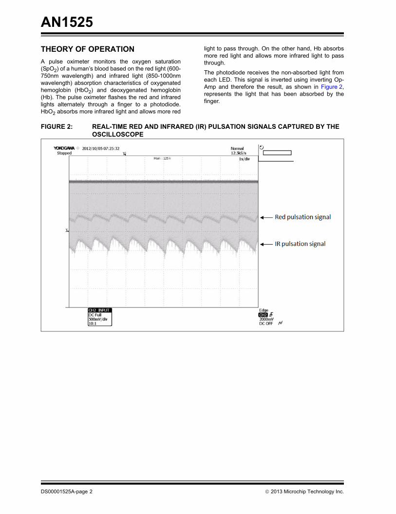
A pulse oximeter monitors the oxygen saturation(SpO2) of a human’s blood based on the red light (600-750nm wavelength) and infrared light (850-1000nmwavelength) absorption characteristics of oxygenatedhemoglobin (HbO2) and deoxygenated hemoglobin(Hb). The pulse oximeter flashes the red and infraredlights alternately through a finger to a photodiode.HbO2 absorbs more infrared light and allows more red
light to pass through. On the other hand, Hb absorbsmore red light and allows more infrared light to passthrough.
The photodiode receives the non-absorbed light fromeach LED. This signal is inverted using inverting Op-Amp and therefore the result, as shown in Figure 2,represents the light that has been absorbed by thefinger.
FIGURE 2: REAL-TIME RED AND INFRARED (IR) PULSATION SIGNALS CAPTURED BY THE OSCILLOSCOPE
DS00001525A-page 2 2013 Microchip Technology Inc.
AN1525
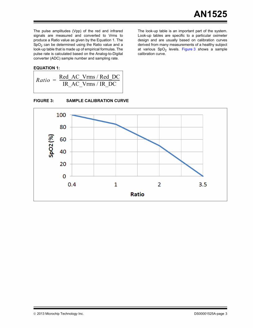
The pulse amplitudes (Vpp) of the red and infraredsignals are measured and converted to Vrms toproduce a Ratio value as given by the Equation 1. TheSpO2 can be determined using the Ratio value and alook-up table that is made up of empirical formulas. Thepulse rate is calculated based on the Analog-to-Digitalconverter (ADC) sample number and sampling rate.
EQUATION 1:
The look-up table is an important part of the system.Look-up tables are specific to a particular oximeterdesign and are usually based on calibration curvesderived from many measurements of a healthy subjectat various SpO2 levels. Figure 3 shows a samplecalibration curve.
FIGURE 3: SAMPLE CALIBRATION CURVE
Ratio Red_AC_Vrms / Red_DCIR_AC_Vrms / IR_DC
---------------------------------------------------------------=
2013 Microchip Technology Inc. DS00001525A-page 3
AN1525
CIRCUIT DESCRIPTION
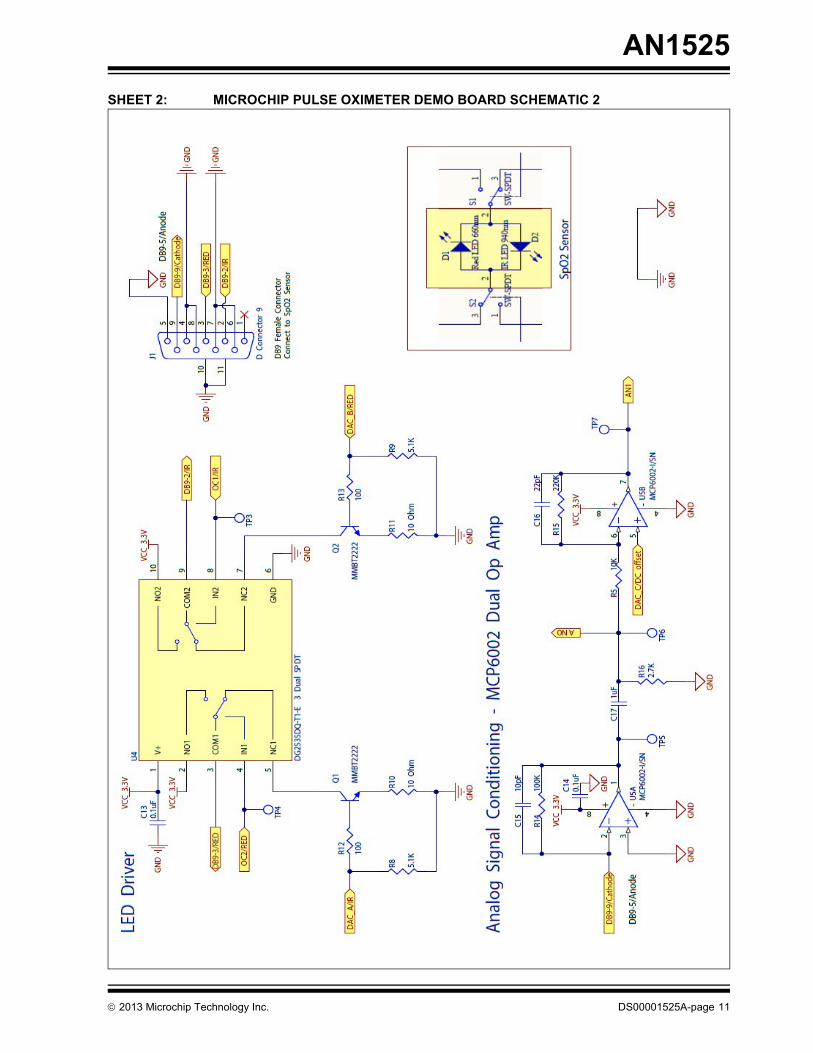
The SpO2 probe used in this example is an off-the-shelfNellcor® compatible finger clip type of probe whichintegrates one red LED and one IR LED and a photodi-ode. The LEDs are controlled by the LED driver circuit.The red light and IR light passing through the finger aredetected by the signal conditioning circuit and are thenfed to a 12-bit Analog-to-Digital Converter (ADC) mod-ule of the microcontroller where %SpO2 can be calc-ulated.
LED Driver circuit
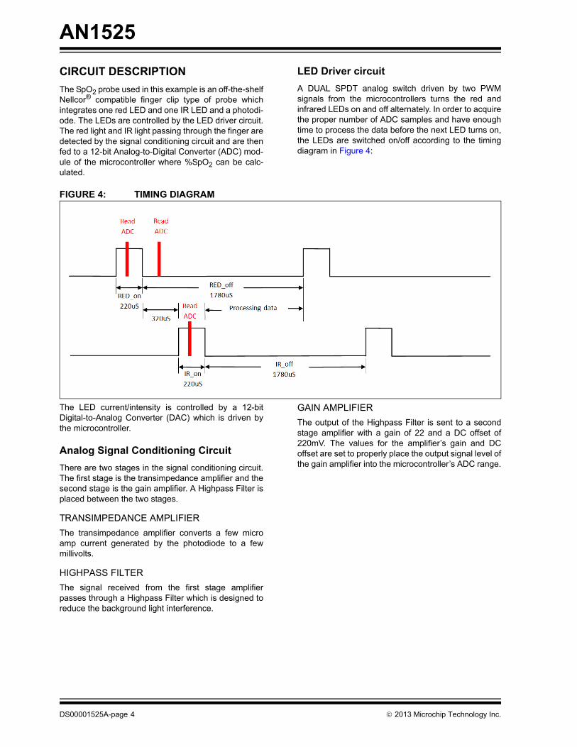
A DUAL SPDT analog switch driven by two PWMsignals from the microcontrollers turns the red andinfrared LEDs on and off alternately. In order to acquirethe proper number of ADC samples and have enoughtime to process the data before the next LED turns on,the LEDs are switched on/off according to the timingdiagram in Figure 4:
FIGURE 4: TIMING DIAGRAM
The LED current/intensity is controlled by a 12-bitDigital-to-Analog Converter (DAC) which is driven bythe microcontroller.
Analog Signal Conditioning Circuit
There are two stages in the signal conditioning circuit.The first stage is the transimpedance amplifier and thesecond stage is the gain amplifier. A Highpass Filter isplaced between the two stages.
TRANSIMPEDANCE AMPLIFIER
The transimpedance amplifier converts a few microamp current generated by the photodiode to a fewmillivolts.
HIGHPASS FILTER
The signal received from the first stage amplifierpasses through a Highpass Filter which is designed toreduce the background light interference.
GAIN AMPLIFIER
The output of the Highpass Filter is sent to a secondstage amplifier with a gain of 22 and a DC offset of220mV. The values for the amplifier’s gain and DCoffset are set to properly place the output signal level ofthe gain amplifier into the microcontroller’s ADC range.
DS00001525A-page 4 2013 Microchip Technology Inc.
AN1525
DIGITAL FILTER DESIGN
The output of the analog signal conditioning circuit isconnected to the ADC module of the dsPIC® DSCsOne ADC sample is taken during each LED’s on-timeperiod and one ADC sample is taken during both LED’soff-time period.
Taking advantage of the powerful Digital SignalProcessing (DSP) engine integrated in the dsPICDSCs, a digital FIR Bandpass Filter is implemented tofilter the ADC data. The filtered data is used to calculatethe pulse amplitude. Digital filter code is generatedusing Microchip’s Digital Filter Design Tool.
FIR Bandpass Filter Specifications
Sampling Frequency (Hz): 500 Passband Ripple (-dB): 0.1
Passband Frequency (Hz): 1 & 5 Stopband Ripple (-dB): 50
Stopband Frequency (Hz): 0.05 & 25 Filter Length: 513
FIR Window: Kaiser
2013 Microchip Technology Inc. DS00001525A-page 5
AN1525
CONNECTIVITY
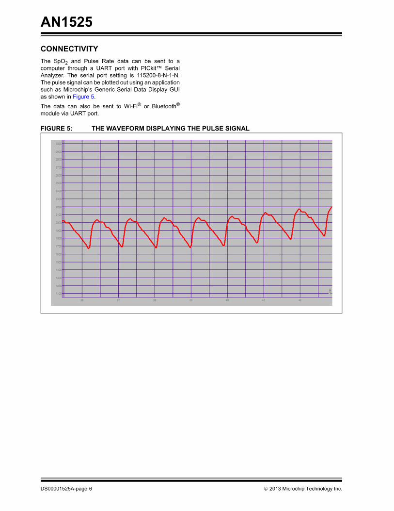
The SpO2 and Pulse Rate data can be sent to acomputer through a UART port with PICkit™ SerialAnalyzer. The serial port setting is 115200-8-N-1-N.The pulse signal can be plotted out using an applicationsuch as Microchip’s Generic Serial Data Display GUIas shown in Figure 5.
The data can also be sent to Wi-Fi® or Bluetooth®
module via UART port.
FIGURE 5: THE WAVEFORM DISPLAYING THE PULSE SIGNAL
DS00001525A-page 6 2013 Microchip Technology Inc.
AN1525
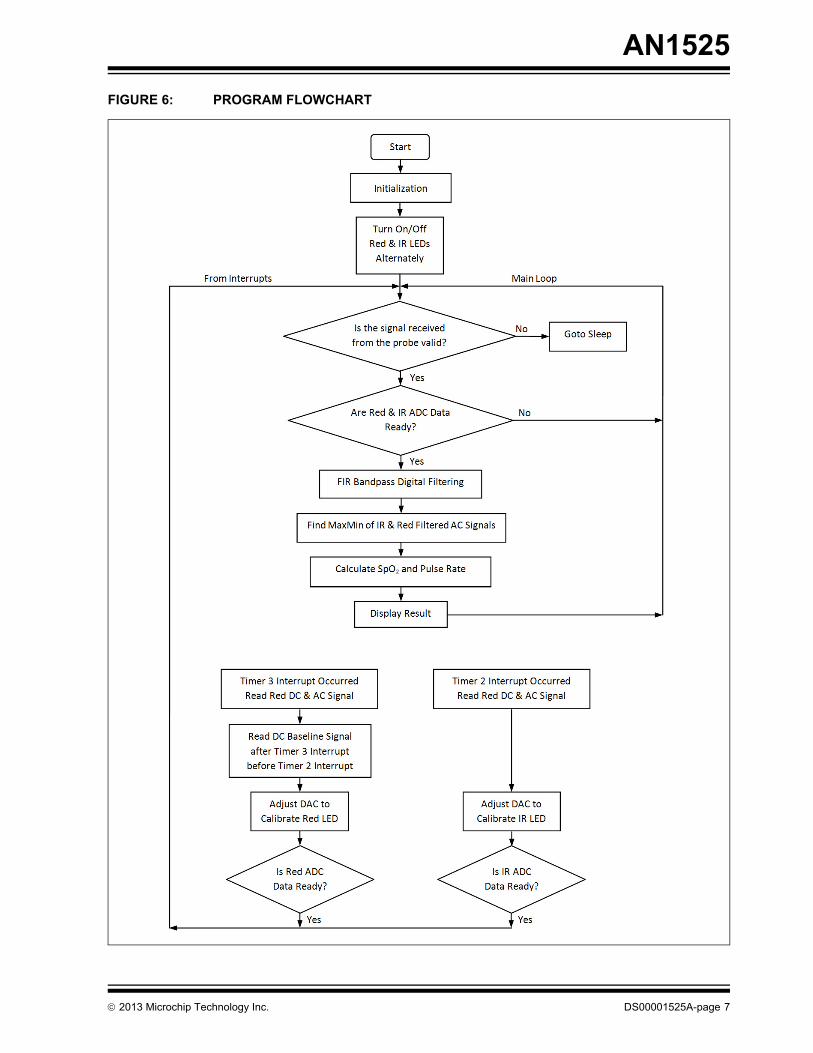
FIGURE 6: PROGRAM FLOWCHART
2013 Microchip Technology Inc. DS00001525A-page 7
AN1525
NOTES:
DS00001525A-page 8 2013 Microchip Technology Inc.
AN1525
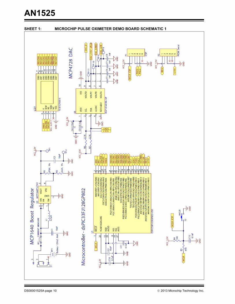
APPENDIX A: SCHEMATICS
This appendix shows the Microchip Pulse Oximeterschematics.
2013 Microchip Technology Inc. DS00001525A-page 9
AN1525
SHEET 1: MICROCHIP PULSE OXIMETER DEMO BOARD SCHEMATIC 1
DS00001525A-page 10 2013 Microchip Technology Inc.
AN1525
SHEET 2: MICROCHIP PULSE OXIMETER DEMO BOARD SCHEMATIC 2
2013 Microchip Technology Inc. DS00001525A-page 11
AN1525
APPENDIX B: MEDICAL DEMO WARNINGS, RESTRICTIONS AND DISCLAIMER
This demo is intended solely for evaluation anddevelopment purposes. It is not intended for medicaldiagnostic use.
APPENDIX C: REFERENCES
AN1494, “Using MCP6491 Op Amps for Photodet-ection Applications”, Microchip Technology Inc.,DS01494, 2013.
DS00001525A-page 12 2013 Microchip Technology Inc.
Note the following details of the code protection feature on Microchip devices:
• Microchip products meet the specification contained in their particular Microchip Data Sheet.
• Microchip believes that its family of products is one of the most secure families of its kind on the market today, when used in the intended manner and under normal conditions.
• There are dishonest and possibly illegal methods used to breach the code protection feature. All of these methods, to our knowledge, require using the Microchip products in a manner outside the operating specifications contained in Microchip’s Data Sheets. Most likely, the person doing so is engaged in theft of intellectual property.
• Microchip is willing to work with the customer who is concerned about the integrity of their code.
• Neither Microchip nor any other semiconductor manufacturer can guarantee the security of their code. Code protection does not mean that we are guaranteeing the product as “unbreakable.”
Code protection is constantly evolving. We at Microchip are committed to continuously improving the code protection features of ourproducts. Attempts to break Microchip’s code protection feature may be a violation of the Digital Millennium Copyright Act. If such actsallow unauthorized access to your software or other copyrighted work, you may have a right to sue for relief under that Act.
Information contained in this publication regarding deviceapplications and the like is provided only for your convenienceand may be superseded by updates. It is your responsibility toensure that your application meets with your specifications.MICROCHIP MAKES NO REPRESENTATIONS ORWARRANTIES OF ANY KIND WHETHER EXPRESS ORIMPLIED, WRITTEN OR ORAL, STATUTORY OROTHERWISE, RELATED TO THE INFORMATION,INCLUDING BUT NOT LIMITED TO ITS CONDITION,QUALITY, PERFORMANCE, MERCHANTABILITY ORFITNESS FOR PURPOSE. Microchip disclaims all liabilityarising from this information and its use. Use of Microchipdevices in life support and/or safety applications is entirely atthe buyer’s risk, and the buyer agrees to defend, indemnify andhold harmless Microchip from any and all damages, claims,suits, or expenses resulting from such use. No licenses areconveyed, implicitly or otherwise, under any Microchipintellectual property rights.
2013 Microchip Technology Inc.
QUALITY MANAGEMENT SYSTEM CERTIFIED BY DNV
== ISO/TS 16949 ==
Trademarks
The Microchip name and logo, the Microchip logo, dsPIC, FlashFlex, KEELOQ, KEELOQ logo, MPLAB, PIC, PICmicro, PICSTART, PIC32 logo, rfPIC, SST, SST Logo, SuperFlash and UNI/O are registered trademarks of Microchip Technology Incorporated in the U.S.A. and other countries.
FilterLab, Hampshire, HI-TECH C, Linear Active Thermistor, MTP, SEEVAL and The Embedded Control Solutions Company are registered trademarks of Microchip Technology Incorporated in the U.S.A.
Silicon Storage Technology is a registered trademark of Microchip Technology Inc. in other countries.
Analog-for-the-Digital Age, Application Maestro, BodyCom, chipKIT, chipKIT logo, CodeGuard, dsPICDEM, dsPICDEM.net, dsPICworks, dsSPEAK, ECAN, ECONOMONITOR, FanSense, HI-TIDE, In-Circuit Serial Programming, ICSP, Mindi, MiWi, MPASM, MPF, MPLAB Certified logo, MPLIB, MPLINK, mTouch, Omniscient Code Generation, PICC, PICC-18, PICDEM, PICDEM.net, PICkit, PICtail, REAL ICE, rfLAB, Select Mode, SQI, Serial Quad I/O, Total Endurance, TSHARC, UniWinDriver, WiperLock, ZENA and Z-Scale are trademarks of Microchip Technology Incorporated in the U.S.A. and other countries.
SQTP is a service mark of Microchip Technology Incorporated in the U.S.A.
GestIC and ULPP are registered trademarks of Microchip Technology Germany II GmbH & Co. KG, a subsidiary of Microchip Technology Inc., in other countries.
All other trademarks mentioned herein are property of their respective companies.
© 2013, Microchip Technology Incorporated, Printed in the U.S.A., All Rights Reserved.
Printed on recycled paper.
ISBN: 978-1-62077-222-5
DS00001525A-page 13
Microchip received ISO/TS-16949:2009 certification for its worldwide headquarters, design and wafer fabrication facilities in Chandler and Tempe, Arizona; Gresham, Oregon and design centers in California and India. The Company’s quality system processes and procedures are for its PIC® MCUs and dsPIC® DSCs, KEELOQ® code hopping devices, Serial EEPROMs, microperipherals, nonvolatile memory and analog products. In addition, Microchip’s quality system for the design and manufacture of development systems is ISO 9001:2000 certified.
DS00001525A-page 14 2013 Microchip Technology Inc.
AMERICASCorporate Office2355 West Chandler Blvd.Chandler, AZ 85224-6199Tel: 480-792-7200 Fax: 480-792-7277Technical Support: http://www.microchip.com/supportWeb Address: www.microchip.com
AtlantaDuluth, GA Tel: 678-957-9614 Fax: 678-957-1455
BostonWestborough, MA Tel: 774-760-0087 Fax: 774-760-0088
ChicagoItasca, IL Tel: 630-285-0071 Fax: 630-285-0075
ClevelandIndependence, OH Tel: 216-447-0464 Fax: 216-447-0643
DallasAddison, TX Tel: 972-818-7423 Fax: 972-818-2924
DetroitFarmington Hills, MI Tel: 248-538-2250Fax: 248-538-2260
IndianapolisNoblesville, IN Tel: 317-773-8323Fax: 317-773-5453
Los AngelesMission Viejo, CA Tel: 949-462-9523 Fax: 949-462-9608
Santa ClaraSanta Clara, CA Tel: 408-961-6444Fax: 408-961-6445
TorontoMississauga, Ontario, CanadaTel: 905-673-0699 Fax: 905-673-6509
ASIA/PACIFICAsia Pacific OfficeSuites 3707-14, 37th FloorTower 6, The GatewayHarbour City, KowloonHong KongTel: 852-2401-1200Fax: 852-2401-3431
Australia - SydneyTel: 61-2-9868-6733Fax: 61-2-9868-6755
China - BeijingTel: 86-10-8569-7000 Fax: 86-10-8528-2104
China - ChengduTel: 86-28-8665-5511Fax: 86-28-8665-7889
China - ChongqingTel: 86-23-8980-9588Fax: 86-23-8980-9500
China - HangzhouTel: 86-571-2819-3187 Fax: 86-571-2819-3189
China - Hong Kong SARTel: 852-2943-5100 Fax: 852-2401-3431
China - NanjingTel: 86-25-8473-2460Fax: 86-25-8473-2470
China - QingdaoTel: 86-532-8502-7355Fax: 86-532-8502-7205
China - ShanghaiTel: 86-21-5407-5533 Fax: 86-21-5407-5066
China - ShenyangTel: 86-24-2334-2829Fax: 86-24-2334-2393
China - ShenzhenTel: 86-755-8864-2200 Fax: 86-755-8203-1760
China - WuhanTel: 86-27-5980-5300Fax: 86-27-5980-5118
China - XianTel: 86-29-8833-7252Fax: 86-29-8833-7256
China - XiamenTel: 86-592-2388138 Fax: 86-592-2388130
China - ZhuhaiTel: 86-756-3210040 Fax: 86-756-3210049
ASIA/PACIFICIndia - BangaloreTel: 91-80-3090-4444 Fax: 91-80-3090-4123
India - New DelhiTel: 91-11-4160-8631Fax: 91-11-4160-8632
India - PuneTel: 91-20-2566-1512Fax: 91-20-2566-1513
Japan - OsakaTel: 81-6-6152-7160 Fax: 81-6-6152-9310
Japan - TokyoTel: 81-3-6880- 3770 Fax: 81-3-6880-3771
Korea - DaeguTel: 82-53-744-4301Fax: 82-53-744-4302
Korea - SeoulTel: 82-2-554-7200Fax: 82-2-558-5932 or 82-2-558-5934
Malaysia - Kuala LumpurTel: 60-3-6201-9857Fax: 60-3-6201-9859
Malaysia - PenangTel: 60-4-227-8870Fax: 60-4-227-4068
Philippines - ManilaTel: 63-2-634-9065Fax: 63-2-634-9069
SingaporeTel: 65-6334-8870Fax: 65-6334-8850
Taiwan - Hsin ChuTel: 886-3-5778-366Fax: 886-3-5770-955
Taiwan - KaohsiungTel: 886-7-213-7828Fax: 886-7-330-9305
Taiwan - TaipeiTel: 886-2-2508-8600 Fax: 886-2-2508-0102
Thailand - BangkokTel: 66-2-694-1351Fax: 66-2-694-1350
EUROPEAustria - WelsTel: 43-7242-2244-39Fax: 43-7242-2244-393Denmark - CopenhagenTel: 45-4450-2828 Fax: 45-4485-2829
France - ParisTel: 33-1-69-53-63-20 Fax: 33-1-69-30-90-79
Germany - MunichTel: 49-89-627-144-0 Fax: 49-89-627-144-44
Italy - Milan Tel: 39-0331-742611 Fax: 39-0331-466781
Netherlands - DrunenTel: 31-416-690399 Fax: 31-416-690340
Spain - MadridTel: 34-91-708-08-90Fax: 34-91-708-08-91
UK - WokinghamTel: 44-118-921-5869Fax: 44-118-921-5820
Worldwide Sales and Service
11/29/12