Embed Size (px)
Citation preview

TrustedTM
AN-T80003
Issue 1 Feb 07 AN-T80003 1
Application Note
TrustedTM System Mechanical Build
This application note explains the mechanical fitting of the TrustedTM chassis and accessories into a 19” rack. This includes mounting details for:
T8100 Processor Chassis
T8300 Expander Chassis
T8270 Fan Tray Rack Mounted
T824x Power Shelves
T8292 MCB Power Distribution Unit
T8290/T8297 Output Power Distribution Unit
Issue Record Issue Number
Date Revised by Technical Check
Authorised by Modification
1 Feb 07 Nick Owens Ray Brown Pete Stock Initial Issue
TrustedTM
AN-T80003 TrustedTM System Mechanical Build
Issue 1 Feb 07 AN-T80003 2
Mechanical Assembly
The following steps defines a recommended procedure for fitting TrustedTM chassis and accessories into a 19” rack.
1. Mount the TrustedTM Power Supply (T8240) into the swingframe as required. The T8240 Power Shelves require T8247 support brackets to be fitted first and secured by fitting the first power shelf with M5 x 12 Pan Head Taptite screws and large plain and crinkle washers through the support brackets. The power shelf must then be secured to the support bracket using four M3 x 6 slotted cheesehead screws or similar with a plain washer.
2. Mount the TrustedTM Controller and Expander Chassis into the swingframe as required. 2U of rack height above and below each controller and expander chassis must be provided to allow the installation of fan trays and vents. The chassis are secured in position using M5 x 12 Pan Head Taptite screws and large plain and crinkle washers through the inner pair of holes on each chassis mounting flange.
3. Mount a TrustedTM Fan Tray Unit above each chassis. Fixings are through the fan tray grille and ears using 4-off M5 x Pan Head 12 Taptite screws, crinkle and M5 plastic cup washers. Fan tray units must be fitted AFTER the module chassis to avoid fouling of the chassis power connector.
4. Check the alignment of the chassis and fan tray units on the front of the swingframe.
5. Fit plastic facia ears over the mounting ears of each module chassis. Fixings are M5 x 12 Pan Head Taptite screws and crinkle washers.
6. Fit blanking plates to mask off unused rack space.
Swingframe
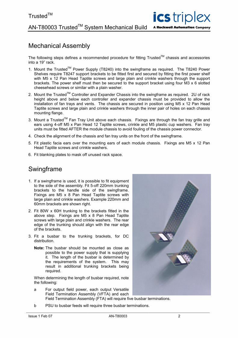
1. If a swingframe is used, it is possible to fit equipment to the side of the assembly. Fit 5-off 220mm trunking brackets to the handle side of the swingframe. Fixings are M5 x 8 Pan Head Taptite screws with large plain and crinkle washers. Example 220mm and 60mm brackets are shown right.
2. Fit 80W x 60H trunking to the brackets fitted in the above step. Fixings are M5 x 8 Pan Head Taptite screws with large plain and crinkle washers. The rear edge of the trunking should align with the rear edge of the brackets.
3. Fit a busbar to the trunking brackets, for DC distribution.
Note: The busbar should be mounted as close as possible to the power supply that is supplying it. The length of the busbar is determined by the requirements of the system. This may result in additional trunking brackets being required.
When determining the length of busbar required, note the following:
a For output field power, each output Versatile Field Termination Assembly (VFTA) and each Field Termination Assembly (FTA) will require five busbar terminations.
b PSU to busbar feeds will require three busbar terminations.
TrustedTM
AN-T80003 TrustedTM System Mechanical Build
Issue 1 Feb 07 AN-T80003 3
4. Fit 5-off 60mm trunking brackets to the pivot side of the swingframe. Fixings are M5 x 8 Pan Head Taptite screws with large plain and crinkle washers.
5. Fit 60W x 40H x 1775mm long trunking to the brackets fitted above. Locate the trunking as close to the front of the swingframe as possible. Fixings are M5 x 8 Pan Head Taptite screws with large plain and crinkle washers. This trunking will be used for the power supply chassis incoming feeders.
6. Fit a saddle to the rear end bracket at the required position for the power supply chassis incoming power supply feeders ‘swing point’.
7. Fit a TS35 DIN Rail 1775mm long to the trunking brackets on the handle side of the swingframe. Fixings are M5 x 8 Pan Head Taptite screws with large plain and crinkle washers.
8. Check that the ‘Top Hat’ bracket on the rear of the controller and expander chassis are fitted to the pivot side of the swingframe.
9. Fit saddles to each of the ‘Top Hat’ brackets on the rear of the controller and expander chassis. These are ‘swing points’ to carry I/O cables etc. from each chassis to the back of panel ‘swing points’.
Output Power Distribution
The following procedures must be implemented where the controller or expander chassis contain TrustedTM Output modules:
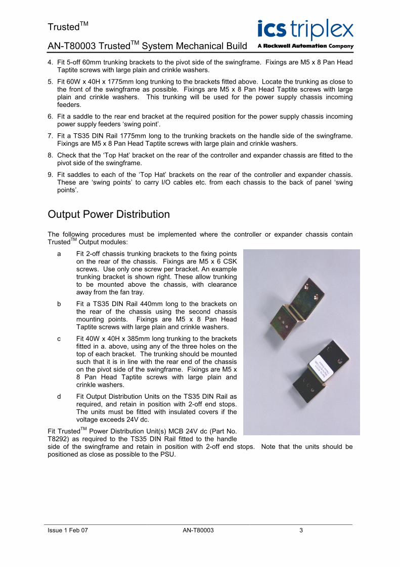
a Fit 2-off chassis trunking brackets to the fixing points on the rear of the chassis. Fixings are M5 x 6 CSK screws. Use only one screw per bracket. An example trunking bracket is shown right. These allow trunking to be mounted above the chassis, with clearance away from the fan tray.
b Fit a TS35 DIN Rail 440mm long to the brackets on the rear of the chassis using the second chassis mounting points. Fixings are M5 x 8 Pan Head Taptite screws with large plain and crinkle washers.
c Fit 40W x 40H x 385mm long trunking to the brackets fitted in a. above, using any of the three holes on the top of each bracket. The trunking should be mounted such that it is in line with the rear end of the chassis on the pivot side of the swingframe. Fixings are M5 x 8 Pan Head Taptite screws with large plain and crinkle washers.
d Fit Output Distribution Units on the TS35 DIN Rail as required, and retain in position with 2-off end stops. The units must be fitted with insulated covers if the voltage exceeds 24V dc.
Fit TrustedTM Power Distribution Unit(s) MCB 24V dc (Part No. T8292) as required to the TS35 DIN Rail fitted to the handle side of the swingframe and retain in position with 2-off end stops. Note that the units should be positioned as close as possible to the PSU.
TrustedTM
AN-T80003 TrustedTM System Mechanical Build
Issue 1 Feb 07 AN-T80003 4
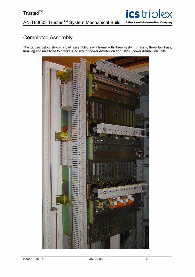
Completed Assembly
The picture below shows a part assembled swingframe with three system chassis, three fan trays, trunking and rails fitted to brackets, MCBs for power distribution and T8290 power distribution units.
TrustedTM
AN-T80003 TrustedTM System Mechanical Build
Issue 1 Feb 07 AN-T80003 5
I/O Connectors
The I/O connectors to the chassis backplane are DIN 41612 type connectors, and are mounted in either a single or a double connector hood. The double connector hood enables TrustedTM I/O Interfaces (of the same type) to be installed in a Companion Slot configuration in adjacent slots.
To install an I/O connector in the chassis backplane:
1. Ensure the correct connector and chassis backplane slot are selected
2. Ensure the associated chassis slot is not occupied by a module
3. Present the I/O connector to the chassis backplane slot, taking care to align the four lugs of the connector with the four cut-outs of the slot
4. Push the I/O connector in and upwards into the slot until the I/O connector latch engages with the chassis slot backplane-lip
5. Ensure that the I/O connector is secure in its chassis slot
Connection at the other end of the cable may be via a similar connection or via a flying lead – see the appropriate Product Descriptions for full details of I/O cable types.
Module Installation
Before initial module installation, ensure that the supply voltage levels have been checked and are within tolerance, and that the I/O connector and hood are correctly latched in place. Ensure that an anti-static wrist strap is worn and that it is suitably earthed.
To install the module:
1. Insert the release key to disengage the ejector levers.
2. Move the upper and lower ejector levers in an upward and downward direction respectively to disengage the levers.
3. Holding the ejector levers, carefully insert the module into its chassis slot (the modules are self-aligning);
4. Push the module fully home;
5. Press the ejector levers to the housed position until they click onto the ejector lever retaining clip, This ensures that the module is correctly secured.
TrustedTM Shields
TrustedTM Shields are fitted with baffle plates designed to assist and direct the flow of air through the chassis where module slots are unoccupied.
All unoccupied module slots MUST be fitted with TrustedTM Shields detailed as follows:
1. T8191 – Single-width slots.
2. T8193 – Triple-width slots.

ICS Triplex technologies and services are available worldwide.
Regional Headquarters:
Americas:
4325 West Sam Houston
Parkway North, Suite 100
Houston
Texas 77043-1219
USA
Tel: +1 713 353 2400
Fax: +1 713 353 2401
Europe, ME & Africa:
Hall Road
Maldon Essex
CM9 4LA
UK
Tel: +44 1621 854444
Fax: +44 1621 851531
Asia Pacific:
Unit 2/12 Keegan Street
O’Connor
Western Australia
Tel: +61 89 314 7787
Fax: +61 89 314 7786
www.icstriplex.com
For technical support email: [email protected]
Sales enquiries: [email protected]
Technology Driven Customer Led