Embed Size (px)
Citation preview
AN UNCERTAINTY ANALYSIS FOR A POSITIVE DISPLACEMENT LIQUID
FLOW CALIBRATOR USING THE WATER DRAW TECHNIQUE
Wesley B. England
U.S. Army Primary Standards Laboratory
AMSAM-TMD-SL
Redstone Arsenal, AL 35898
[email protected] Abstract - This paper is an uncertainty analysis performed by the Liquid Flow Lab of the Army Primary Standards Laboratory (APSL) for the calibration of positive displacement piston prover using a volumetric water draw. The water draw calibration is conducted to establish a precise relationship between translator pulses and the volume of liquid displaced by the draw and is known as the K-Factor (given in pulses/unit volume). For the APSL the term “Water Draw” is a misnomer, because the APSL uses hydrocarbons that are already in the flow calibrator at the time of the draw calibration.
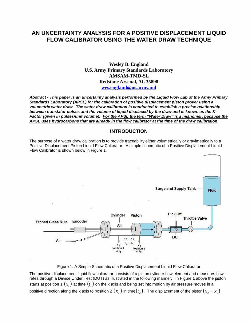
INTRODUCTION The purpose of a water draw calibration is to provide traceability either volumetrically or gravimetrically to a Positive Displacement Piston Liquid Flow Calibrator. A simple schematic of a Positive Displacement Liquid Flow Calibrator is shown below in Figure 1.
.
Figure 1. A Simple Schematic of a Positive Displacement Liquid Flow Calibrator
The positive displacement liquid flow calibrator consists of a piston cylinder flow element and measures flow rates through a Device Under Test (DUT) as illustrated in the following manner. In Figure 1 above the piston
starts at position 1 1x at time 1t on the x axis and being set into motion by air pressure moves in a
positive direction along the x axis to position 2 2x in time 2t . The displacement of the piston 12 xx
divided by the time duration it took for the piston to move from position 1 to position 2 12 tt gives us the
rate in [Unit Length/Unit Time] the piston has traveled in the positive x direction and is given by the following expression.
dt
dx
t
x
tt
xxRate
12
12 (1)
Since the piston and cylinder are circular, the area of the piston cylinder arrangement is given by 2rA and
if we know the radius of the circle we can calculate its area. If we multiply the constant area by the rate in
Equation 1 the volumetric flow rate
v in [Unit Volume/Unit Time] of the positive displacement calibrator can
easily be determined (see Equation 2 below).
dt
dv
dt
dxr
dt
dxARateAreav
2 (2)
The distance x, traveled by the piston in Figure 1 is determined by a graduated etched glass rule (with a
typical grating pitch of 20m) that is read by an encoder which produces a pulse each time a graduation on the rule is encountered. The rate the piston travels in the x direction is influenced by the Throttle Valve. If the area of the piston cylinder element has been measured one can easily determine the volume flow as the area times the distance traveled. However, a water draw calibration can be performed to determine how many translator pulses are required to fill a flask of a precisely known calibrated volume thus not having to disassemble the piston cylinder element to do a dimensional calibration. Instead, a K-factor for the liquid flow calibrator can be determined in pulses per unit volume as illustrated in Equation 3 below.
VolumeUnit
Pulses
V
PK Calibrator
C_
(3)
The water draw calibration [1] is conducted to establish a precise relationship between translator pulses and the volume of liquid displaced by the draw. The piston of the calibrator is set into motion displacing the liquid medium into a flask of a precisely known volume while the translator counts the number of pulses required to fill the flask to its fill line. Corrections for temperature and pressure are then made to determine a calibration constant for the prover. This process is repeated several times to establish an average and obtain a repeatability figure for the calibration. Although this technique is referred to as a “water draw”, it is a misnomer, because the draws conducted by the Army Primary Standards Laboratory (APSL) Flow Laboratory will use media other than water. Typically, water is used because its properties are better understood than all other liquid media. While this provides a lower uncertainty draw, it requires removing the old liquid media in the prover, cleaning the prover with solvent, and filling the prover with clean water. This process is wasteful, tedious, and time consuming. Furthermore, water has an erosive effect on the piston prover surfaces and is hard on the piston prover seals. It is for this reason that the APSL Flow Laboratory chooses not to use water. The APSL Flow Laboratory keeps the ambient environment of the piston provers at a temperature of 68° F ± 3.6 ° F (20 °C ±2 °C) and a relative humidity of 20% to 70%. This uncertainty analysis was conducted at these conditions and therefore is only valid at these conditions.
Calculations and Corrections
Calculations The calibrator constant is determined as follows:
V
pK
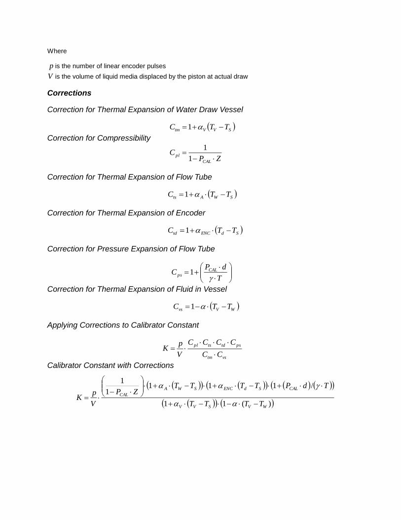
Where p is the number of linear encoder pulses
V is the volume of liquid media displaced by the piston at actual draw
Corrections
Correction for Thermal Expansion of Water Draw Vessel
SVVtm TTC 1
Correction for Compressibility
ZP
CCAL
pl
1
1
Correction for Thermal Expansion of Flow Tube
SWAts TTC 1
Correction for Thermal Expansion of Encoder
SdENCtd TTC 1
Correction for Pressure Expansion of Flow Tube
T
dPC CAL
ps
1
Correction for Thermal Expansion of Fluid in Vessel
WVvs TTC 1
Applying Corrections to Calibrator Constant
vstm
pstdtspl
CC
CCCC
V
pK
Calibrator Constant with Corrections
)(11
/1111
1
WVSVV
CALSdENCSWA
CAL
TTTT
TdPTTTTZP
V
pK
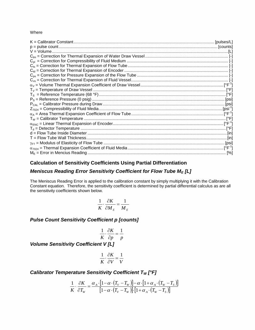
Where K = Calibrator Constant .......................................................................................................................... [pulses/L] p = pulse count .......................................................................................................................................... [counts] V = Volume ......................................................................................................................................................... [L] Ctm = Correction for Thermal Expansion of Water Draw Vessel ........................................................................ [-] Cpl = Correction for Compressibility of Fluid Medium ........................................................................................ [-] Cts = Correction for Thermal Expansion of Flow Tube ....................................................................................... [-] Ctd = Correction for Thermal Expansion of Encoder .......................................................................................... [-] Cps = Correction for Pressure Expansion of the Flow Tube ............................................................................... [-] Cvs = Correction for Thermal Expansion of Fluid Vessel .................................................................................... [-]
V = Volume Thermal Expansion Coefficient of Draw Vessel ........................................................................ [°F-1
] TV = Temperature of Draw Vessel ................................................................................................................... [°F] TS = Reference Temperature (68 °F) .............................................................................................................. [°F] PS = Reference Pressure (0 psig) ................................................................................................................... [psi] PCAL = Calibrator Pressure during Draw .......................................................................................................... [psi] Z7024 = Compressibility of Fluid Media ........................................................................................................... [psi
-1]
A = Area Thermal Expansion Coefficient of Flow Tube ................................................................................ [°F-1
] TW = Calibrator Temperature ........................................................................................................................... [°F]
ENC = Linear Thermal Expansion of Encoder................................................................................................ [°F-1
] Td = Detector Temperature .............................................................................................................................. [°F] d = Flow Tube Inside Diameter ......................................................................................................................... [in] T = Flow Tube Wall Thickness .......................................................................................................................... [in]
FT = Modulus of Elasticity of Flow Tube ......................................................................................................... [psi]
7024 = Thermal Expansion Coefficient of Fluid Media ................................................................................... [°F-1
] ME = Error in Mencius Reading ........................................................................................................................ [%]
Calculation of Sensitivity Coefficients Using Partial Differentiation
Meniscus Reading Error Sensitivity Coefficient for Flow Tube ME [L] The Meniscus Reading Error is applied to the calibration constant by simply multiplying it with the Calibration Constant equation. Therefore, the sensitivity coefficient is determined by partial differential calculus as are all the sensitivity coefficients shown below.
EE MM
K
K
11
Pulse Count Sensitivity Coefficient p [counts]
pp
K
K
11
Volume Sensitivity Coefficient V [L]
VV
K
K
11
Calibrator Temperature Sensitivity Coefficient TW [°F]
SWAWV
SWAWVA
W TTTT
TTTT
T
K
K
11
111
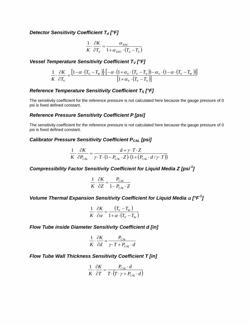
Detector Sensitivity Coefficient Td [°F]
SdENC
ENC
d TTT
K
K
1
1
Vessel Temperature Sensitivity Coefficient TV [°F]
SVV
WVVSVVWV
V TT
TTTTTT
T
K
K
1
1111
Reference Temperature Sensitivity Coefficient TS [°F] The sensitivity coefficient for the reference pressure is not calculated here because the gauge pressure of 0 psi is fixed defined constant.
Reference Pressure Sensitivity Coefficient P [psi] The sensitivity coefficient for the reference pressure is not calculated here because the gauge pressure of 0 psi is fixed defined constant.
Calibrator Pressure Sensitivity Coefficient PCAL [psi]
TdPZPT
ZTd
P
K
K CALCALCAL
/11
1
Compressibility Factor Sensitivity Coefficient for Liquid Media Z [psi-1
]
ZP
P
Z
K
K CAL
CAL
1
1
Volume Thermal Expansion Sensitivity Coefficient for Liquid Media [°F-1
]
WV
WV
TT
TTK
K
1
1
Flow Tube inside Diameter Sensitivity Coefficient d [in]
dPT
P
d
K
K CAL
CAL
1
Flow Tube Wall Thickness Sensitivity Coefficient T [in]
dPTT
dP
T
K
K CAL
CAL
1
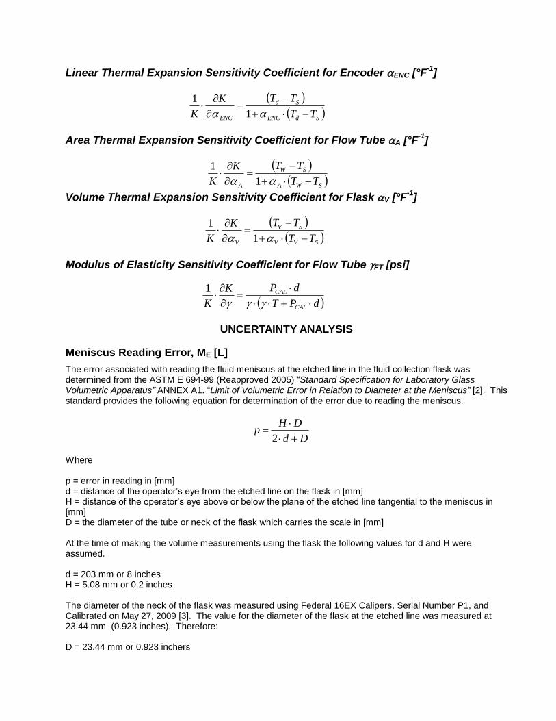
Linear Thermal Expansion Sensitivity Coefficient for Encoder ENC [°F-1
]
SdENC
Sd
ENC TT
TTK
K
1
1
Area Thermal Expansion Sensitivity Coefficient for Flow Tube A [°F-1
]
SWA
SW
A TT
TTK
K
1
1
Volume Thermal Expansion Sensitivity Coefficient for Flask V [°F-1
]
SVV
SV
V TT
TTK
K
1
1
Modulus of Elasticity Sensitivity Coefficient for Flow Tube FT [psi]
dPT
dPK
K CAL
CAL
1
UNCERTAINTY ANALYSIS
Meniscus Reading Error, ME [L]
The error associated with reading the fluid meniscus at the etched line in the fluid collection flask was determined from the ASTM E 694-99 (Reapproved 2005) “Standard Specification for Laboratory Glass Volumetric Apparatus” ANNEX A1. “Limit of Volumetric Error in Relation to Diameter at the Meniscus” [2]. This standard provides the following equation for determination of the error due to reading the meniscus.
Dd
DHp
2
Where p = error in reading in [mm] d = distance of the operator’s eye from the etched line on the flask in [mm] H = distance of the operator’s eye above or below the plane of the etched line tangential to the meniscus in [mm] D = the diameter of the tube or neck of the flask which carries the scale in [mm] At the time of making the volume measurements using the flask the following values for d and H were assumed. d = 203 mm or 8 inches H = 5.08 mm or 0.2 inches The diameter of the neck of the flask was measured using Federal 16EX Calipers, Serial Number P1, and Calibrated on May 27, 2009 [3]. The value for the diameter of the flask at the etched line was measured at 23.44 mm (0.923 inches). Therefore: D = 23.44 mm or 0.923 inchers
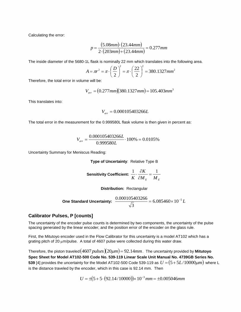
Calculating the error:
mmmmmm
mmmmp 277.0
44.232032
44.2308.5
The inside diameter of the 5680-1L flask is nominally 22 mm which translates into the following area.
2
22
2 1327.3802
22
2mm
DrA
Therefore, the total error in volume will be:
3403.1051327.380277.0 mmmmmmVerr
This translates into:
LVerr 660001054032.0
The total error in the measurement for the 0.999580L flask volume is then given in percent as:
%0105.0%100999580.0
660001054032.0
L
LVerr
Uncertainty Summary for Meniscus Reading:
Type of Uncertainty: Relative Type B
Sensitivity Coefficient:
EE MM
K
K
11
Distribution: Rectangular
One Standard Uncertainty: L510085460.63
660001054032.0
Calibrator Pulses, P [counts]
The uncertainty of the encoder pulse counts is determined by two components, the uncertainty of the pulse spacing generated by the linear encoder; and the position error of the encoder on the glass rule. First, the Mitutoyo encoder used in the Flow Calibrator for this uncertainty is a model AT102 which has a
grating pitch of 20 m/pulse. A total of 4607 pulse were collected during this water draw.
Therefore, the piston traveled mmmpulses 14.92204607 . The uncertainty provided by Mitutoyo
Spec Sheet for Model AT102-500 Code No. 539-119 Linear Scale Unit Manual No. 4739GB Series No.
539 [4] provides the uncertainty for the Model AT102-500 Code 539-119 as mLU 10000/55 where L
is the distance traveled by the encoder, which in this case is 92.14 mm. Then
mmmmU 005046.01010000/14.9255 3
With a grating pitch of 20 m/pulse this can be converted into
pulsespulsemm 2523.0/1020/10005046.0 63
The total number of pulses collected during a water draw was 4607. Converting to percent error we obtain the following.
%0055.0%1004607
2523.0
pulses
pulses
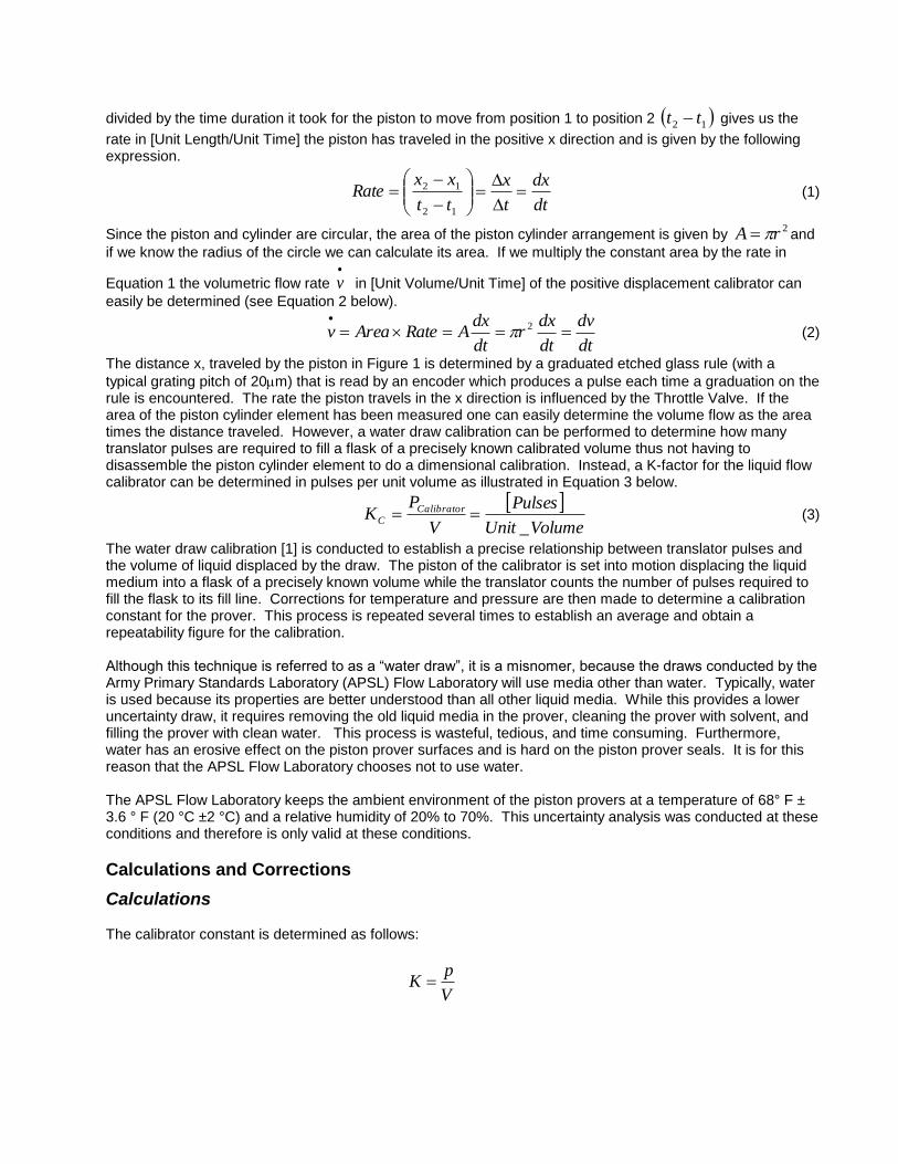
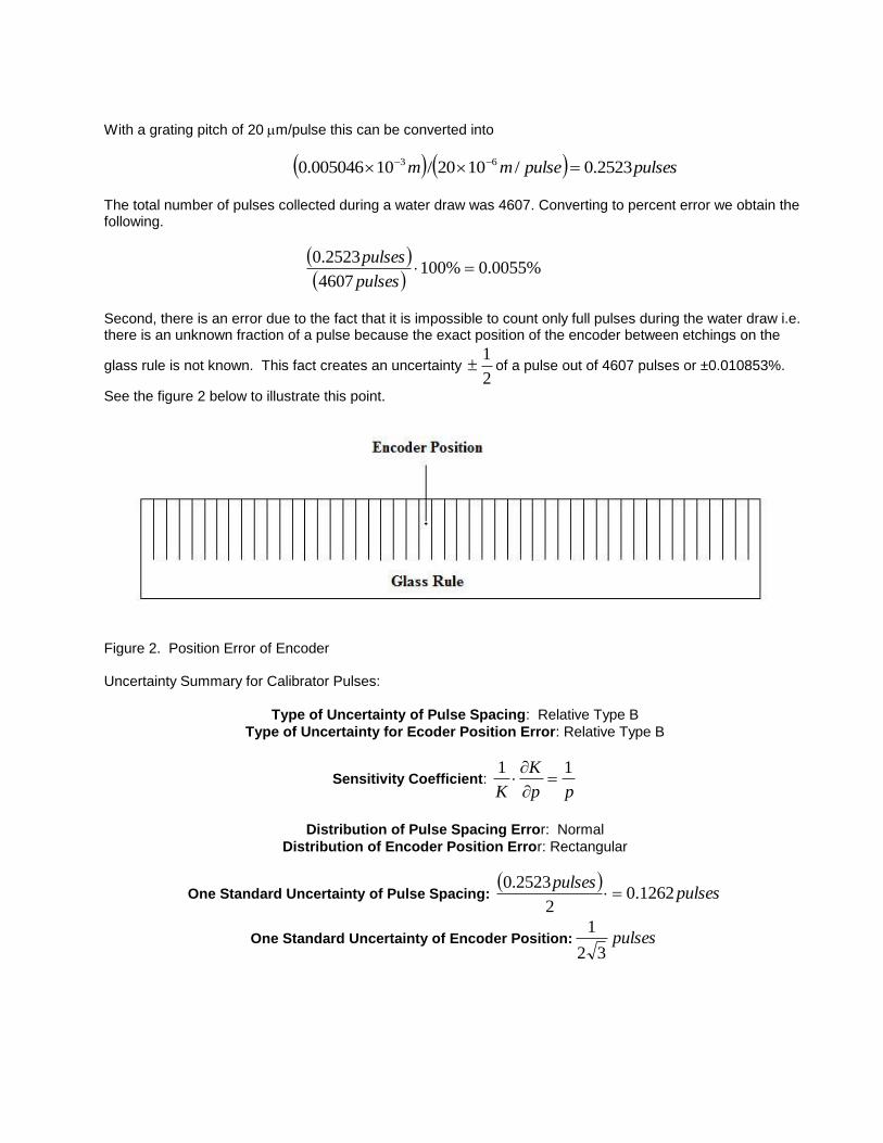
Second, there is an error due to the fact that it is impossible to count only full pulses during the water draw i.e. there is an unknown fraction of a pulse because the exact position of the encoder between etchings on the
glass rule is not known. This fact creates an uncertainty 2
1 of a pulse out of 4607 pulses or ±0.010853%.
See the figure 2 below to illustrate this point.
Figure 2. Position Error of Encoder Uncertainty Summary for Calibrator Pulses:
Type of Uncertainty of Pulse Spacing: Relative Type B
Type of Uncertainty for Ecoder Position Error: Relative Type B
Sensitivity Coefficient: pp
K
K
11
Distribution of Pulse Spacing Error: Normal
Distribution of Encoder Position Error: Rectangular
One Standard Uncertainty of Pulse Spacing:
pulsespulses
1262.02
2523.0
One Standard Uncertainty of Encoder Position: pulses32
1
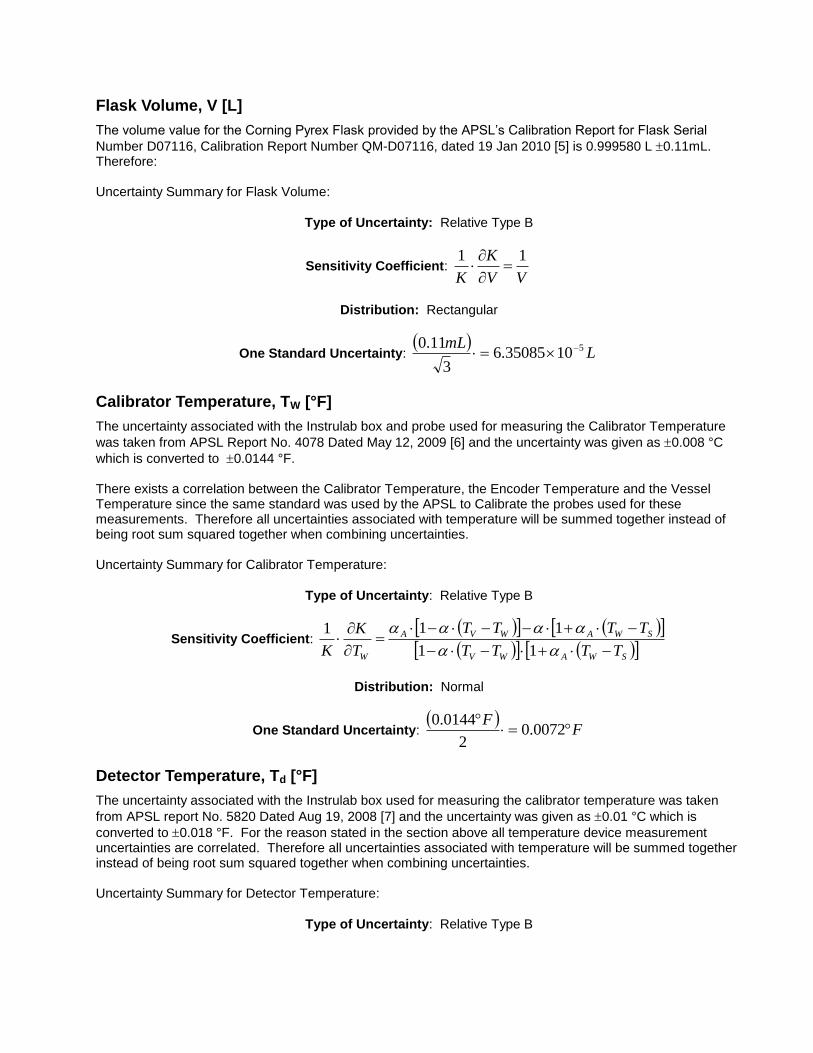
Flask Volume, V [L]
The volume value for the Corning Pyrex Flask provided by the APSL’s Calibration Report for Flask Serial
Number D07116, Calibration Report Number QM-D07116, dated 19 Jan 2010 [5] is 0.999580 L 0.11mL. Therefore: Uncertainty Summary for Flask Volume:
Type of Uncertainty: Relative Type B
Sensitivity Coefficient: VV
K
K
11
Distribution: Rectangular
One Standard Uncertainty:
LmL 51035085.63
11.0
Calibrator Temperature, TW [°F]
The uncertainty associated with the Instrulab box and probe used for measuring the Calibrator Temperature
was taken from APSL Report No. 4078 Dated May 12, 2009 [6] and the uncertainty was given as 0.008 °C
which is converted to 0.0144 °F. There exists a correlation between the Calibrator Temperature, the Encoder Temperature and the Vessel Temperature since the same standard was used by the APSL to Calibrate the probes used for these measurements. Therefore all uncertainties associated with temperature will be summed together instead of being root sum squared together when combining uncertainties. Uncertainty Summary for Calibrator Temperature:
Type of Uncertainty: Relative Type B
Sensitivity Coefficient: SWAWV
SWAWVA
W TTTT
TTTT
T
K
K
11
111
Distribution: Normal
One Standard Uncertainty:
FF
0072.02
0144.0
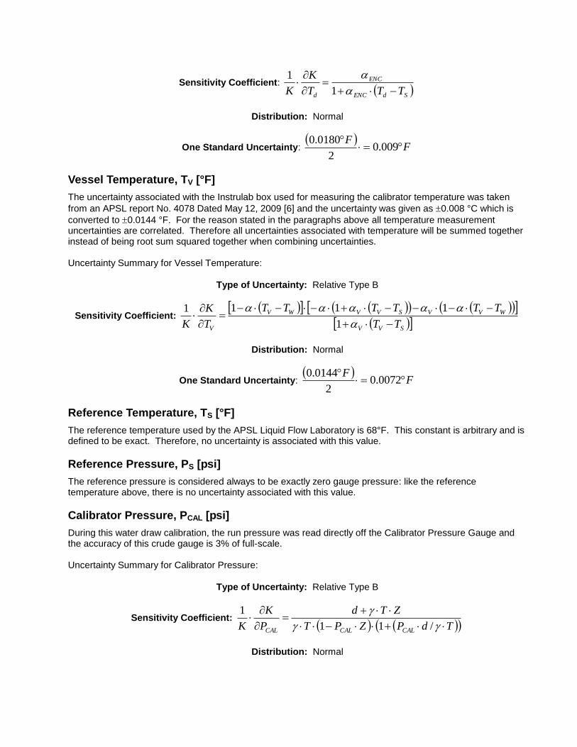
Detector Temperature, Td [°F]
The uncertainty associated with the Instrulab box used for measuring the calibrator temperature was taken
from APSL report No. 5820 Dated Aug 19, 2008 [7] and the uncertainty was given as 0.01 °C which is
converted to 0.018 °F. For the reason stated in the section above all temperature device measurement uncertainties are correlated. Therefore all uncertainties associated with temperature will be summed together instead of being root sum squared together when combining uncertainties. Uncertainty Summary for Detector Temperature:
Type of Uncertainty: Relative Type B
Sensitivity Coefficient: SdENC
ENC
d TTT
K
K
1
1
Distribution: Normal
One Standard Uncertainty:
FF
009.02
0180.0
Vessel Temperature, TV [°F]
The uncertainty associated with the Instrulab box used for measuring the calibrator temperature was taken
from an APSL report No. 4078 Dated May 12, 2009 [6] and the uncertainty was given as 0.008 °C which is
converted to 0.0144 °F. For the reason stated in the paragraphs above all temperature measurement uncertainties are correlated. Therefore all uncertainties associated with temperature will be summed together instead of being root sum squared together when combining uncertainties. Uncertainty Summary for Vessel Temperature:
Type of Uncertainty: Relative Type B
Sensitivity Coefficient:
SVV
WVVSVVWV
V TT
TTTTTT
T
K
K
1
1111
Distribution: Normal
One Standard Uncertainty:
FF
0072.02
0144.0
Reference Temperature, TS [°F]
The reference temperature used by the APSL Liquid Flow Laboratory is 68°F. This constant is arbitrary and is defined to be exact. Therefore, no uncertainty is associated with this value.
Reference Pressure, PS [psi]
The reference pressure is considered always to be exactly zero gauge pressure: like the reference temperature above, there is no uncertainty associated with this value.
Calibrator Pressure, PCAL [psi]
During this water draw calibration, the run pressure was read directly off the Calibrator Pressure Gauge and the accuracy of this crude gauge is 3% of full-scale. Uncertainty Summary for Calibrator Pressure:
Type of Uncertainty: Relative Type B
Sensitivity Coefficient: TdPZPT
ZTd
P
K
K CALCALCAL
/11
1
Distribution: Normal
One Standard Uncertainty:
psipsi
4.22
160)100/3(
Compressibility Factor of MIL-PRF-7024E Type II and Gear Oil Mixture, Z7024 & Oil [psi-1
]
The compressibility factor for MIL-C-7024 and oil mixture was determined from using “API Manual of Petroleum Measurement Standards Chapter 11.2.1M-Compressability Factors for Hydrocarbons: 638-1074 Kilograms per cubic Metre Range First Edition”, August 1984 (Range related to density (15 degrees C) and Metering Temperature (degrees Celsius) [8]. The actual density of a sample of the mixture was measured with an Anton Paar DMA 5000 M and determined to be 0.8113 g/cm
3. The number corresponding to 0.8113
g/cm3 density was located on page 76 of the manual. This number was interpolated from the tables and
determined to be 0.848. According to the API standard this number was to be divided my 1x10⁶. Therefore
the following was obtained.
kPakPa 7
61048.8
101
848.0
Converting kPa to psi the following is obtained.
psi
kPa 66
10846754.5kPa/psi 01 738 037 0.145
1048.8
The recommended uncertainty by COSM and COPM Survey is 0.1% which is outlined in Section 11.2.1.5.1M of “API MPM CH 11.2.1M Compressibility Factors for Hydrocarbons: 638 - 1074 Kilograms per Cubic Metre
Range” [11]. Therefore, kPapsi 96 10847.510847.5100/%1.0 .
Uncertainty Summary for Compressibility Factor for MIL-PRF-7024E Type II and Gear Oil Mixture:
Type of Uncertainty: Relative Type B
Sensitivity Coefficient: ZP
P
Z
K
K CAL
CAL
1
1
Distribution: Rectangular
One Standard Uncertainty:
psipsi 9
9
10376.33
10847.5
Volume Thermal Expansion Coefficient of MIL-PRF-7024E Type II and Gear Oil Mix,
7024 & Oil [°F-1
]
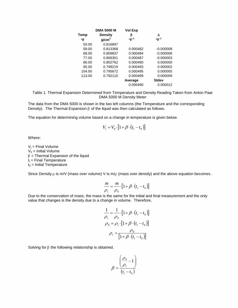
Using an Anton Paar DMA 5000 M, the value for the thermal expansion coefficient was calculated from a set of measurements that were taken over the operating range of the Flow Calibrator used in this uncertainty. These measurements are shown below in Table 1.
DMA 5000 M Vol Exp
Temp Density b
°F g/cm3
°F-1
°F-1
50.00 0.816897
59.00 0.813368 0.000482 -0.000008
68.00 0.809837 0.000484 -0.000006
77.00 0.806301 0.000487 -0.000003
86.00 0.802762 0.000490 0.000000
95.00 0.799219 0.000493 0.000002
104.00 0.795672 0.000495 0.000005
113.00 0.792115 0.000499 0.000009
Average Stdev
0.000490 0.000012
Table 1. Thermal Expansion Determined from Temperature and Density Reading Taken from Anton Paar DMA 5000 M Density Meter
The data from the DMA 5000 is shown in the two left columns (the Temperature and the corresponding
Density). The Thermal Expansion b of the liquid was then calculated as follows. The equation for determining volume based on a change in temperature is given below.
00 1 ttVV tt b
Where: Vt = Final Volume V0 = Initial Volume
b = Thermal Expansion of the liquid tt = Final Temperature t0 = Initial Temperature
Since Density is m/V (mass over volume) V is m/ (mass over density) and the above equation becomes.
0
0
1 ttmm
t
t
b
Due to the conservation of mass, the mass is the same for the initial and final measurement and the only value that changes is the density due to a change in volume. Therefore,
0
0
111
ttt
t
b
00 1 tttt b
0
0
1 ttt
t
b
Solving for b the following relationship is obtained.
0
0 1
ttt
t
b
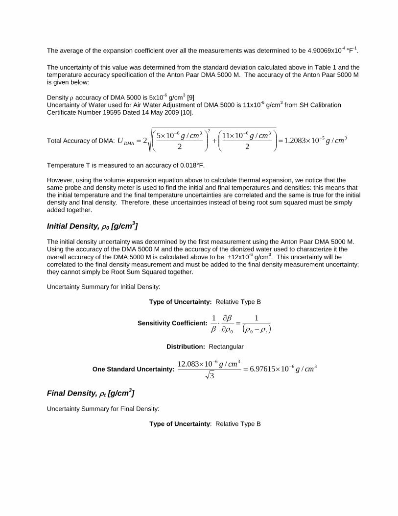
The average of the expansion coefficient over all the measurements was determined to be 4.90069x10⁻⁴
°F-1
.
The uncertainty of this value was determined from the standard deviation calculated above in Table 1 and the temperature accuracy specification of the Anton Paar DMA 5000 M. The accuracy of the Anton Paar 5000 M is given below:
Density accuracy of DMA 5000 is 5x10⁻⁶
g/cm3 [9]
Uncertainty of Water used for Air Water Adjustment of DMA 5000 is 11x10-6
g/cm3 from SH Calibration
Certificate Number 19595 Dated 14 May 2009 [10].
Total Accuracy of DMA: 35
362
36
/102083.12
/1011
2
/1052 cmg
cmgcmgU DMA
Temperature T is measured to an accuracy of 0.018°F. However, using the volume expansion equation above to calculate thermal expansion, we notice that the same probe and density meter is used to find the initial and final temperatures and densities: this means that the initial temperature and the final temperature uncertainties are correlated and the same is true for the initial density and final density. Therefore, these uncertainties instead of being root sum squared must be simply added together.
Initial Density, 0 [g/cm3]
The initial density uncertainty was determined by the first measurement using the Anton Paar DMA 5000 M. Using the accuracy of the DMA 5000 M and the accuracy of the dionized water used to characterize it the
overall accuracy of the DMA 5000 M is calculated above to be 12x10-6
g/cm3. This uncertainty will be
correlated to the final density measurement and must be added to the final density measurement uncertainty; they cannot simply be Root Sum Squared together. Uncertainty Summary for Initial Density:
Type of Uncertainty: Relative Type B
Sensitivity Coefficient: t
b
b
00
11
Distribution: Rectangular
One Standard Uncertainty: 36
36
/1097615.63
/10083.12cmg
cmg
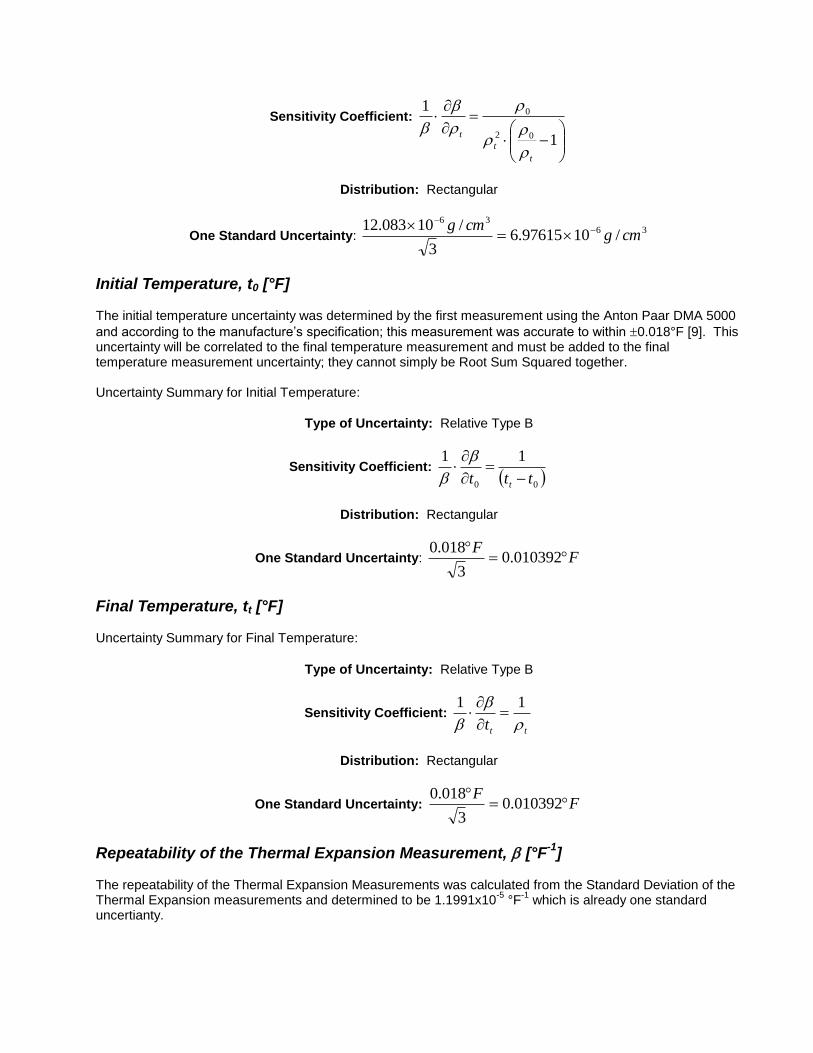
Final Density, t [g/cm3]
Uncertainty Summary for Final Density:
Type of Uncertainty: Relative Type B
Sensitivity Coefficient:
1
1
02
0
t
t
t
b
b
Distribution: Rectangular
One Standard Uncertainty: 36
36
/1097615.63
/10083.12cmg
cmg
Initial Temperature, t0 [°F] The initial temperature uncertainty was determined by the first measurement using the Anton Paar DMA 5000
and according to the manufacture’s specification; this measurement was accurate to within 0.018°F [9]. This uncertainty will be correlated to the final temperature measurement and must be added to the final temperature measurement uncertainty; they cannot simply be Root Sum Squared together. Uncertainty Summary for Initial Temperature:
Type of Uncertainty: Relative Type B
Sensitivity Coefficient: 00
11
ttt t
b
b
Distribution: Rectangular
One Standard Uncertainty: FF
010392.03
018.0
Final Temperature, tt [°F] Uncertainty Summary for Final Temperature:
Type of Uncertainty: Relative Type B
Sensitivity Coefficient:
ttt
b
b
11
Distribution: Rectangular
One Standard Uncertainty: FF
010392.03
018.0
Repeatability of the Thermal Expansion Measurement, b [°F-1
] The repeatability of the Thermal Expansion Measurements was calculated from the Standard Deviation of the Thermal Expansion measurements and determined to be 1.1991x10
-5 °F
-1 which is already one standard
uncertianty.
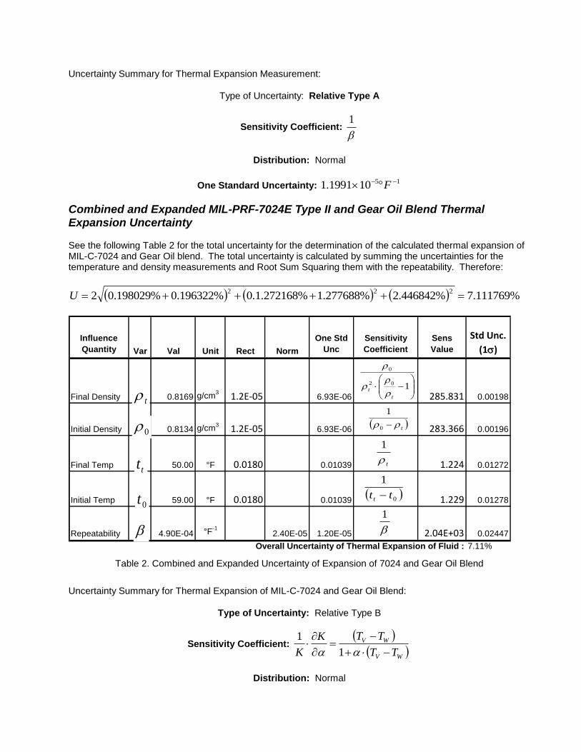
Uncertainty Summary for Thermal Expansion Measurement:
Type of Uncertainty: Relative Type A
Sensitivity Coefficient: b
1
Distribution: Normal
One Standard Uncertainty: 15101991.1 F
Combined and Expanded MIL-PRF-7024E Type II and Gear Oil Blend Thermal Expansion Uncertainty See the following Table 2 for the total uncertainty for the determination of the calculated thermal expansion of MIL-C-7024 and Gear Oil blend. The total uncertainty is calculated by summing the uncertainties for the temperature and density measurements and Root Sum Squaring them with the repeatability. Therefore:
%111769.7%446842.2%277688.1%272168.1.0%196322.0%198029.02222U
Influence
Quantity Var Val Unit Rect Norm
One Std
Unc
Sensitivity
Coefficient
Sens
Value
Std Unc.
(1s)
Final Density 0.8169 g/cm3
1.2E-05 6.93E-06 285.831 0.00198
Initial Density 0.8134 g/cm3
1.2E-05 6.93E-06 283.366 0.00196
Final Temp 50.00 °F 0.0180 0.01039 1.224 0.01272
Initial Temp 59.00 °F 0.0180 0.01039 1.229 0.01278
Repeatability 4.90E-04 °F-1
2.40E-05 1.20E-05 2.04E+03 0.02447
Overall Uncertainty of Thermal Expansion of Fluid : 7.11%
0
t
tt
0t
b
102
0
t
t
t 0
1
t
1
0
1
tt t
b
1
Table 2. Combined and Expanded Uncertainty of Expansion of 7024 and Gear Oil Blend
Uncertainty Summary for Thermal Expansion of MIL-C-7024 and Gear Oil Blend:
Type of Uncertainty: Relative Type B
Sensitivity Coefficient:
WV
WV
TT
TTK
K
1
1
Distribution: Normal
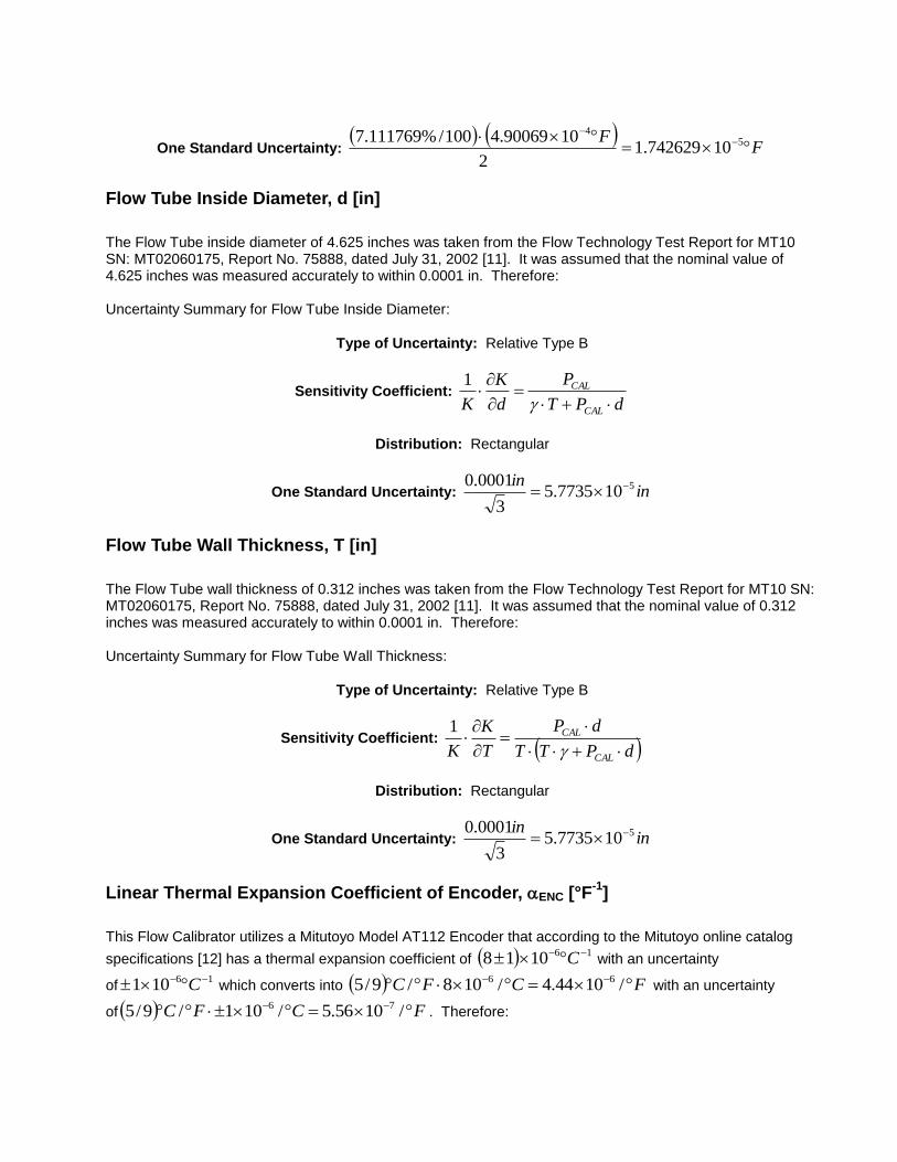
One Standard Uncertainty:
FF
5
4
10742629.12
1090069.4100/%111769.7
Flow Tube Inside Diameter, d [in]
The Flow Tube inside diameter of 4.625 inches was taken from the Flow Technology Test Report for MT10 SN: MT02060175, Report No. 75888, dated July 31, 2002 [11]. It was assumed that the nominal value of 4.625 inches was measured accurately to within 0.0001 in. Therefore: Uncertainty Summary for Flow Tube Inside Diameter:
Type of Uncertainty: Relative Type B
Sensitivity Coefficient: dPT
P
d
K
K CAL
CAL
1
Distribution: Rectangular
One Standard Uncertainty: inin 5107735.5
3
0001.0
Flow Tube Wall Thickness, T [in]
The Flow Tube wall thickness of 0.312 inches was taken from the Flow Technology Test Report for MT10 SN: MT02060175, Report No. 75888, dated July 31, 2002 [11]. It was assumed that the nominal value of 0.312 inches was measured accurately to within 0.0001 in. Therefore: Uncertainty Summary for Flow Tube Wall Thickness:
Type of Uncertainty: Relative Type B
Sensitivity Coefficient: dPTT
dP
T
K
K CAL
CAL
1
Distribution: Rectangular
One Standard Uncertainty: inin 5107735.5
3
0001.0
Linear Thermal Expansion Coefficient of Encoder, ENC [°F-1
]
This Flow Calibrator utilizes a Mitutoyo Model AT112 Encoder that according to the Mitutoyo online catalog
specifications [12] has a thermal expansion coefficient of 161018 C with an uncertainty
of16101 C which converts into FCFC /1044.4/108/9/5 66
with an uncertainty
of FCFC /1056.5/101/9/5 76. Therefore:
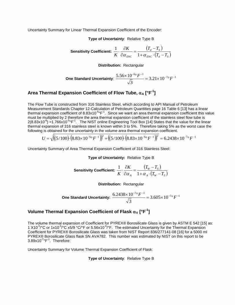
Uncertainty Summary for Linear Thermal Expansion Coefficient of the Encoder:
Type of Uncertainty: Relative Type B
Sensitivity Coefficient:
SdENC
Sd
ENC TT
TTK
K
1
1
Distribution: Rectangular
One Standard Uncertainty: 17
16
1021.33
1056.5
FF
Area Thermal Expansion Coefficient of Flow Tube, A [°F-1
]
The Flow Tube is constructed from 316 Stainless Steel, which according to API Manual of Petroleum Measurement Standards Chapter 12-Calculation of Petroleum Quantities page 16 Table 6 [13] has a linear thermal expansion coefficient of 8.83x10
-6°F
-1. Since we want an area thermal expansion coefficient this value
must be multiplied by 2 therefore the area thermal expansion coefficient of the stainless steel flow tube is 2(8.83x10
-6) =1.766x10
-5°F
-1. The NIST online Engineering Tool Box [14] States that the value for the linear
thermal expansion of 316 stainless steel is known within 3 to 5%. Therefore taking 5% as the worst case the following is obtained for the uncertainty in the volume area thermal expansion coefficient.
17216216 102438.61083.8100/51083.8100/5 FFFU
Uncertainty Summary of Area Thermal Expansion Coefficient of 316 Stainless Steel:
Type of Uncertainty: Relative Type B
Sensitivity Coefficient:
SWA
SW
A TT
TTK
K
1
1
Distribution: Rectangular
One Standard Uncertainty: 17
17
10605.33
102438.6
FF
Volume Thermal Expansion Coefficient of Flask V [°F-1
]
The volume thermal expansion of Coefficient for PYREX® Borosilicate Glass is given by ASTM E 542 [15] as: 1 X10
-5/°C or 1x10
-5/°C x5/9 °C/°F or 5.56x10
-6/°F. The estimated Uncertainty for the Thermal Expansion
Coefficient for PYREX® Borosilicate Glass was taken from NIST Report 836/277141-08 [16] for a 5000 ml PYREX® Borosilicate Glass flask SN AVA782. This number was estimated by NIST on this report to be 3.89x10
-7°F
-1. Therefore:
Uncertainty Summary for Volume Thermal Expansion Coefficient of Flask:
Type of Uncertainty: Relative Type B
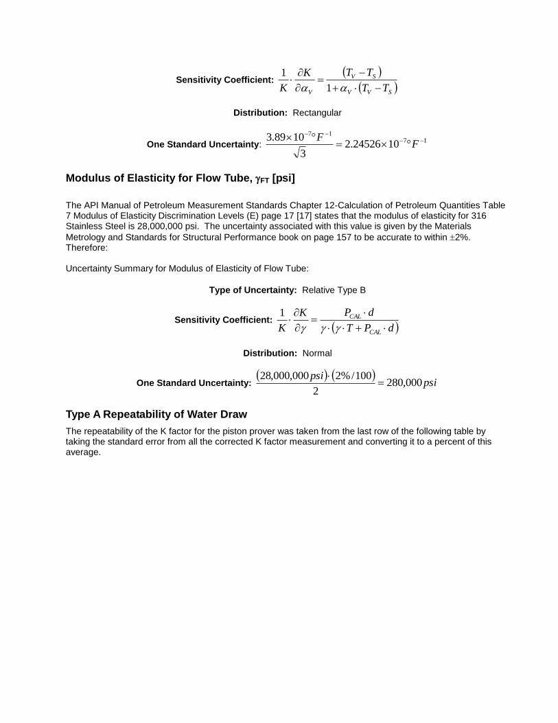
Sensitivity Coefficient:
SVV
SV
V TT
TTK
K
1
1
Distribution: Rectangular
One Standard Uncertainty: 17
17
1024526.23
1089.3
FF
Modulus of Elasticity for Flow Tube, FT [psi]
The API Manual of Petroleum Measurement Standards Chapter 12-Calculation of Petroleum Quantities Table 7 Modulus of Elasticity Discrimination Levels (E) page 17 [17] states that the modulus of elasticity for 316 Stainless Steel is 28,000,000 psi. The uncertainty associated with this value is given by the Materials
Metrology and Standards for Structural Performance book on page 157 to be accurate to within 2%. Therefore: Uncertainty Summary for Modulus of Elasticity of Flow Tube:
Type of Uncertainty: Relative Type B
Sensitivity Coefficient: dPT
dPK
K CAL
CAL
1
Distribution: Normal
One Standard Uncertainty:
psipsi
000,2802
100/%2000,000,28
Type A Repeatability of Water Draw
The repeatability of the K factor for the piston prover was taken from the last row of the following table by taking the standard error from all the corrected K factor measurement and converting it to a percent of this average.
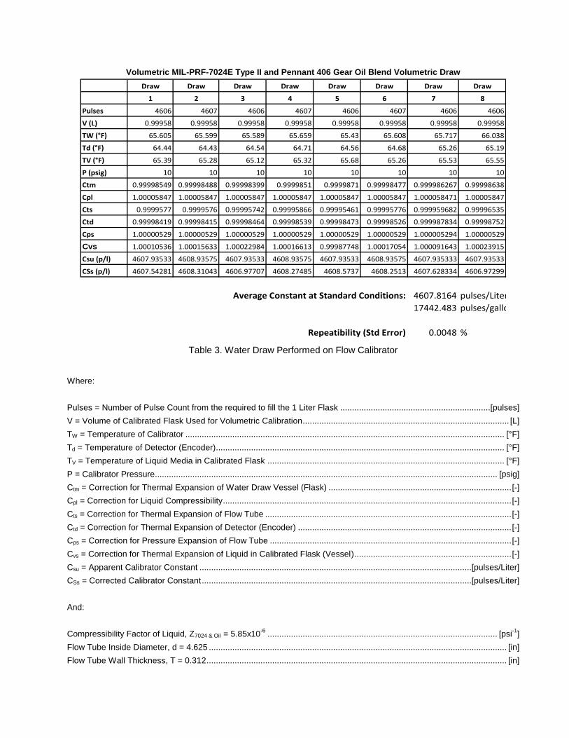
Volumetric MIL-PRF-7024E Type II and Pennant 406 Gear Oil Blend Volumetric Draw
Draw Draw Draw Draw Draw Draw Draw Draw
1 2 3 4 5 6 7 8
Pulses 4606 4607 4606 4607 4606 4607 4606 4606
V (L) 0.99958 0.99958 0.99958 0.99958 0.99958 0.99958 0.99958 0.99958
TW (°F) 65.605 65.599 65.589 65.659 65.43 65.608 65.717 66.038
Td (°F) 64.44 64.43 64.54 64.71 64.56 64.68 65.26 65.19
TV (°F) 65.39 65.28 65.12 65.32 65.68 65.26 65.53 65.55
P (psig) 10 10 10 10 10 10 10 10
Ctm 0.99998549 0.99998488 0.99998399 0.9999851 0.9999871 0.99998477 0.999986267 0.99998638
Cpl 1.00005847 1.00005847 1.00005847 1.00005847 1.00005847 1.00005847 1.000058471 1.00005847
Cts 0.9999577 0.9999576 0.99995742 0.99995866 0.99995461 0.99995776 0.999959682 0.99996535
Ctd 0.99998419 0.99998415 0.99998464 0.99998539 0.99998473 0.99998526 0.999987834 0.99998752
Cps 1.00000529 1.00000529 1.00000529 1.00000529 1.00000529 1.00000529 1.000005294 1.00000529
Cvs 1.00010536 1.00015633 1.00022984 1.00016613 0.99987748 1.00017054 1.000091643 1.00023915
Csu (p/l) 4607.93533 4608.93575 4607.93533 4608.93575 4607.93533 4608.93575 4607.935333 4607.93533
CSs (p/l) 4607.54281 4608.31043 4606.97707 4608.27485 4608.5737 4608.2513 4607.628334 4606.97299
Average Constant at Standard Conditions: 4607.8164 pulses/Liter
17442.483 pulses/gallon
Repeatibility (Std Error) 0.0048 %
Table 3. Water Draw Performed on Flow Calibrator
Where:
Pulses = Number of Pulse Count from the required to fill the 1 Liter Flask ................................................................[pulses]
V = Volume of Calibrated Flask Used for Volumetric Calibration........................................................................................ [L]
TW = Temperature of Calibrator ........................................................................................................................................ [°F]
Td = Temperature of Detector (Encoder)........................................................................................................................... [°F]
TV = Temperature of Liquid Media in Calibrated Flask ..................................................................................................... [°F]
P = Calibrator Pressure.................................................................................................................................................. [psig]
Ctm = Correction for Thermal Expansion of Water Draw Vessel (Flask) .............................................................................. [-]
Cpl = Correction for Liquid Compressibility ........................................................................................................................... [-]
Cts = Correction for Thermal Expansion of Flow Tube ......................................................................................................... [-]
Ctd = Correction for Thermal Expansion of Detector (Encoder) ........................................................................................... [-]
Cps = Correction for Pressure Expansion of Flow Tube ....................................................................................................... [-]
Cvs = Correction for Thermal Expansion of Liquid in Calibrated Flask (Vessel) ................................................................... [-]
Csu = Apparent Calibrator Constant ....................................................................................................................[pulses/Liter]
CSs = Corrected Calibrator Constant ...................................................................................................................[pulses/Liter]
And:
Compressibility Factor of Liquid, Z7024 & Oil = 5.85x10⁻⁶
.................................................................................................. [psi-1
]
Flow Tube Inside Diameter, d = 4.625 ............................................................................................................................... [in]
Flow Tube Wall Thickness, T = 0.312 ................................................................................................................................ [in]
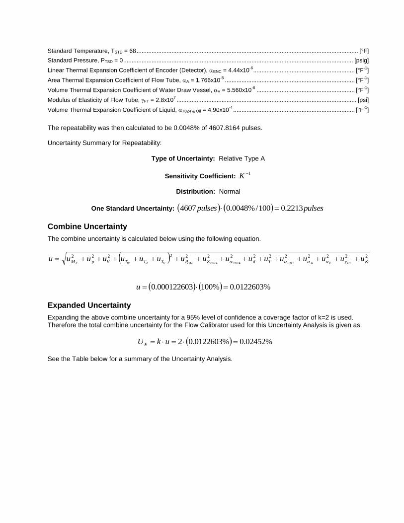
Standard Temperature, TSTD = 68 ..................................................................................................................................... [°F]
Standard Pressure, PTSD = 0 .......................................................................................................................................... [psig]
Linear Thermal Expansion Coefficient of Encoder (Detector), ENC = 4.44x10⁻⁶
............................................................. [°F-1
]
Area Thermal Expansion Coefficient of Flow Tube, A = 1.766x10⁻⁵
.............................................................................. [°F-1
]
Volume Thermal Expansion Coefficient of Water Draw Vessel, V = 5.560x10⁻⁶
........................................................... [°F-1
]
Modulus of Elasticity of Flow Tube, FT = 2.8x10⁷ ............................................................................................................ [psi]
Volume Thermal Expansion Coefficient of Liquid, 7024 & Oil = 4.90x10⁻⁴
......................................................................... [°F-1
]
The repeatability was then calculated to be 0.0048% of 4607.8164 pulses. Uncertainty Summary for Repeatability:
Type of Uncertainty: Relative Type A
Sensitivity Coefficient: 1K
Distribution: Normal
One Standard Uncertainty: pulsespulses 2213.0100/%0048.04607
Combine Uncertainty
The combine uncertainty is calculated below using the following equation.
22222222222222
70247024 KTdZPTTTVpM uuuuuuuuuuuuuuuuuFTVAENCCALVdWE
%0122603.0%100000122603.0 u
Expanded Uncertainty
Expanding the above combine uncertainty for a 95% level of confidence a coverage factor of k=2 is used. Therefore the total combine uncertainty for the Flow Calibrator used for this Uncertainty Analysis is given as:
%02452.0%0122603.02 ukUE
See the Table below for a summary of the Uncertainty Analysis.
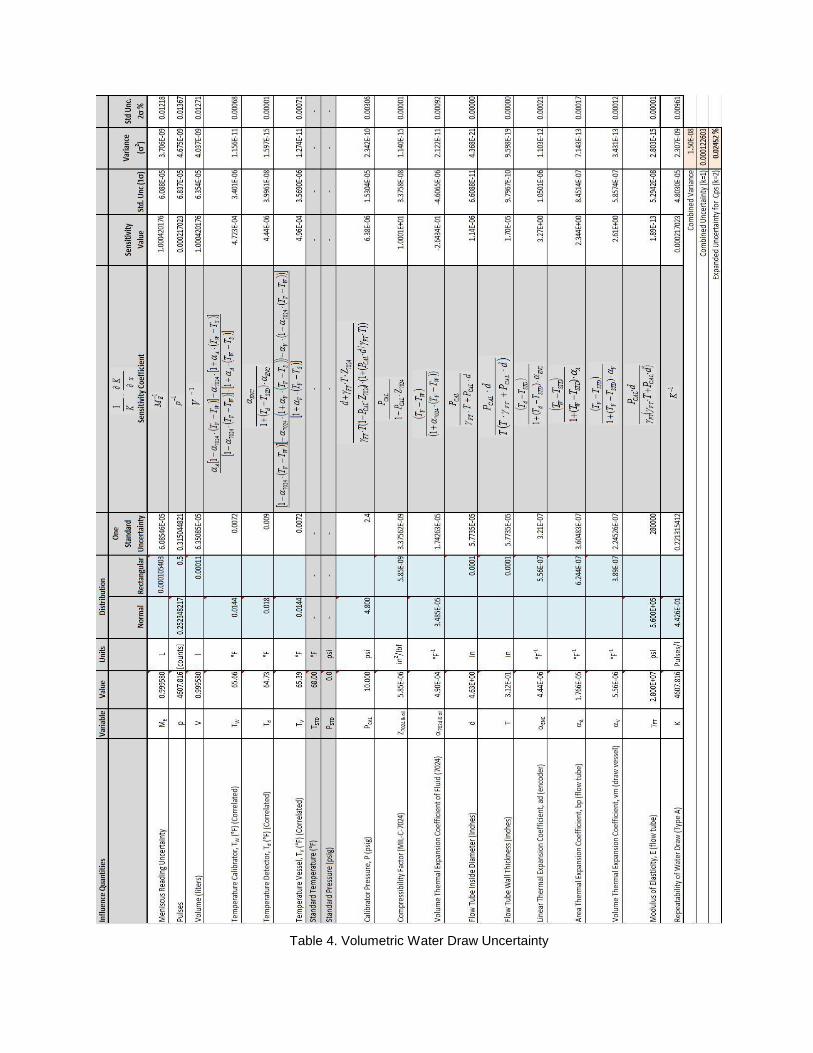
Table 4. Volumetric Water Draw Uncertainty
REFERENCES [1] Water Draw Technique courtesy Steve Hope, CompuFlow Solutions 2009. [2] ASTM E 694-99 (Reapproved 2005) “Standard Specification for Laboratory Glass Volumetric Apparatus,” ANNEX A1. “Limit of Volumetric Error in Relation to Diameter at the Meniscus.” [3] U.S. Army Primary Standards Laboratory Report No. P1, for Federal 16EX Calipers, May 27, 2009. [4] Mitutoyo Spec Sheet for Model AT102-500 Code No. 539-119 Linear Scale Unit, Manual No. 4739GB Series N0. 539. [5] Army Primary Standards Laboratory Calibration Report for Flask Serial Number D07116, Calibration Report Number QM-D07116, Jan 19, 2010. [6] Army Primary Standards Laboratory Calibration Report No. 4078 for Digital Temperature Indicator, May 12, 2009. [7] Army Primary Standards Laboratory Calibration Report No. 5820 for Digital Temperature Indicator, Aug 19, 2008. [8] API Manual of Petroleum Measurement Standards Chapter 11.2.1M-“Compressibility Factors for Hydrocarbons: 638-1074 Kilograms per cubic Metre Range”, First Edition, August 1984 (Range related to density (15 degrees C) and Metering Temperature (degrees Celsius). [9] Anton Paar “Instruction Manual DMA 5000 M,” Document C76IB01E.fm, Sept 2, 2009. [10] SH Calibration Certificate Number 19595 for Certified Pure Water, 14 May 2009. [11] Flow Technology Test Report for MT10 SN: MT02060175, Report No. 75888, Jul 31, 2002. [12] Mitutoyo online catalog specifications. [13] API “Manual of Petroleum Measurement Standards,” Chapter 12-“Calculation of Petroleum Quantities,” page 16 Table 6. [14] NIST Engineering Online Tool Box, 2009. [15] ASTM E 542 “Standard Practice for Calibration of Laboratory Volumetric Apparatus,” E41.10. [16] NIST Report 836/277141-08 for a 5000 ml PYREX® Borosilicate Glass flask SN AVA782. [17] API “Manual of Petroleum Measurement Standards,” Chapter 12-“Calculation of Petroleum Quantities,” Table 7 Modulus of Elasticity Discrimination Levels (E) page 17. [18] ANSI/NCSL Z540 “American National Standard for Calibration – Calibration Laboratories and Measuring and Test Equipment General Requirements,” ANSI/NCSL Z540.1-1994 (R2002). [19] ANSI/NCSL Z540 “American National Standard for Calibration- U.S. Guide to the Expression of Uncertainty in Measurement,” ANSI/NCSL-Z540-2-1997 (R2002).

[20] Adams, Thomas M., “A2LA Guide for the Estimation of Measurement Uncertainty In Testing,” July 2002. A2LA. [21] ISO/IEC 17025 International Standard, “General Requirements for the Competence for Testing and Calibration Laboratories,” 2
nd Ed., May, 15 2005, Reference Number ISO/IEC 17025:2005(E).
[22] Taylor, Barry N. and Kuyatt, Chris E. NIST “Technical Note 1297 Guidelines for Evaluating and Expressing the Uncertainty of NIST Measurement Results,” 1994 Ed.