Embed Size (px)
Citation preview

Order this documentby AN2149/D
Fre
esc
ale
Se
mic
on
du
cto
r, I
nc
...
Semiconductor Products SectorApplication Note
AN2149
Compressor Induction Motor Stall and Rotation Detection using Microcontrollersby William Mackay
Freescale Microcontroller DivisionEast Kilbride, Scotland.
1 Introduction
Domestic refrigeration appliances commonly use single-phase induction motors to drive a compressor pump. The compressor is used to provide and maintain the required refrigerant pressure to allow the fridge compartment to function within the desired pre-selected temperature range. This application note provides a method of detecting a motor stall condition and a means for monitoring rotation during normal run conditions. Motor stall/rotation detection is based on a phase difference measurement between the run and start windings of the motor. This is achieved very conveniently using the timer input capture features available on the Freescale HC908KX8 low cost high performance ‘flash’ Microcontroller.
There is a necessity to provide some form of protection from conditions that may cause the motor windings to sustain thermal damage during start-up. This can be caused by a motor stall condition. If the motor is stalled, overheating will occur fairly rapidly and may cause permanent damage to the Motor windings. For example, mechanical failure of the compressor pump may impair the rotation of the motor and result in a stall condition.
© Motorola, Inc., 2001
For More Information On This Product, Go to: www.freescale.com
Application Note
F
ree
sca
le S
em
ico
nd
uc
tor,
I
Freescale Semiconductor, Inc.n
c..
.
Compressor motors in today’s refrigeration appliances are thermally protected by a bi-metallic contact that is embedded in the motor windings. This contact is in series with the AC line supply to the motor and will open and remove power to the motor when overheating occurs, for example, due to a motor stall condition. This method is suitable only for providing thermal protection of the motor windings. From power-on this can be achieved more efficiently and economically using a Freescale Microcontroller Embedded Solution. The Microcontroller solution has the additional advantage of providing a method of stall detection by detecting the rotation of the motor at start-up and monitoring rotation during normal run conditions.
2 AC Line Zero Cross Detection Hardware
Implementing an efficient motor start procedure can be achieved using a Triac and relay control technique. This involves firstly applying power to the run winding of the motor using the Relay. The Triac is connected in series with the start winding and is fired close to the zero crossing points of the line voltage for a specific period of time to start the motor. After this period the Triac is turned off and the motor continues to run. The start winding provides the initial starting torque and, after the motor has started, it has no further duty until the motor is powered down and re-started. A schematic diagram of the hardware required follows.
AN2149
2 AC Line Zero Cross Detection Hardware For More Information On This Product,
Go to: www.freescale.com

Application NoteDetection Schematic
F
ree
sca
le S
em
ico
nd
uc
tor,
I
Freescale Semiconductor, Inc.n
c..
.
2.1 Detection Schematic
When running, the continuous rotational motion of the motor and magnetic field induces a voltage in the now redundant start winding. During normal running conditions there is a measurable phase difference between the start and run windings. This is illustrated in the following diagrams.
Vdd
Vdd
RELAY
Start Winding
Run Winding
Q2R3110ohm
R11k Q1
R210k
11
R8220k
R1010k
R9220k
R1110k
1
R610k
R5220k
R710k
Q3
Q2R4
220k
1
MT1
MT2
L
FromMic ro
Vss
To Micro
N
TriacDriveCircuitry
Motor
To MicroInputCapture
Vss
StartWindingZeroCrossDetection
To MicroInputCapture
RunWindingZeroCrossDetection
N
Vss
N
AN2149
AC Line Zero Cross Detection Hardware For More Information On This Product,
Go to: www.freescale.com

Application Note
F
ree
sca
le S
em
ico
nd
uc
tor,
I
Freescale Semiconductor, Inc.n
c..
.
2.1.1 Run and Start Winding Before Rotation
In the above stalled condition the windings are in phase.
2.1.2 Phase Difference During Run Condition
Normal run conditions yields a phase difference between the run and start windings.
Run Winding
Start Winding
Run Winding
Start Winding
AN2149
4 AC Line Zero Cross Detection Hardware For More Information On This Product,
Go to: www.freescale.com

Application NotePhase Difference Measurement Process
F
ree
sca
le S
em
ico
nd
uc
tor,
I
Freescale Semiconductor, Inc.n
c..
.
2.2 Phase Difference Measurement Process
The phase difference between the start and run windings is approximately 1mS. The presence of this difference is an indication of motor rotation. When the motor is not rotating, there is no difference in phase between the start and run windings. This change in behavior provides the measurement source for the Microcontroller. The following diagram illustrates the measurement process.
The ‘phase shift’ is the actual phase difference between the run and start windings. ‘phase min’ and ‘phase max’ define the acceptable tolerance band for the detection of the start zero cross point from the run zero cross reference point.
2.3 AC Line Signal Conditioning
The zero cross detect circuit conditions the above waveforms into usable digital signals which result as a series of pulses switched between 0V and Vdd at half the period of the AC line frequency, in this case 10mS. The digital signals derived from the zero crossing points of the run and
Run Zero Cross Start Zero Cross
Phase Shift
Phase Min
Run Winding
Start Winding
Phase Max
AN2149
AC Line Zero Cross Detection Hardware For More Information On This Product,
Go to: www.freescale.com

Application Note
F
ree
sca
le S
em
ico
nd
uc
tor,
I
Freescale Semiconductor, Inc.n
c..
.
start windings are input to the Microcontroller input capture pins. A sample of the digital waveforms applied to the input capture pins follows.
2.3.1 Input to Microcontroller Before Rotation
2.3.2 Input to Microcontroller During Run Condition
This is the digital representation of the phase difference between the run and start windings during normal running conditions.
Start Winding
Run Winding
Run Winding
Start Winding
AN2149
6 AC Line Zero Cross Detection Hardware For More Information On This Product,
Go to: www.freescale.com

Application NoteDetection Algorithm
F
ree
sca
le S
em
ico
nd
uc
tor,
I
Freescale Semiconductor, Inc.n
c..
.
2.4 Detection Algorithm
The algorithm will monitor the continuous presence of pulses on the input capture pins derived from the run and start windings. If the pulses are not detected in the appropriate sequence and time frame, the motor can be considered as being in a stalled condition and appropriate action can be taken, for example, by removing power from the motor and raising an audible alarm. Alternatively, one input capture pin can be used to monitor the run winding and the start winding can be monitored using an input port. This would require additional code to poll the port pin in a timely sense. The method described here takes advantage of both input captures.
2.5 Consecutive Detection
The detection operation is as follows. Every time a zero crossing point is detected on the run winding, it is expected that a zero cross point should be detected on the start winding approximately 1mS later. The timing between the run and start zero cross points is measured with an appropriate tolerance band included in the measurement.
The algorithm is arranged to use the run zero cross points as a time reference. Each time a ‘run’ zero cross point is detected, the ‘run’ interrupt service routine is entered and the time of this event is latched. Approximately 1mS later the start winding zero cross point will be detected and the ‘start’ interrupt service routine will be entered. The time of this event will be latched also.
It is reasonable to expect that noise can influence the quality of the detected signal from either the start or run winding, and to compensate for this possibility, the algorithm will expect that zero cross detections should be consecutive. If for example a ‘run’ winding zero cross point is detected and the corresponding ‘start’ zero cross point is not detected within the expected time, this event will be identified as an error. A predefined number of non-consecutive zero cross errors will be tolerated before power-down and alarm action is invoked.
AN2149
AC Line Zero Cross Detection Hardware For More Information On This Product,
Go to: www.freescale.com

Application Note
F
ree
sca
le S
em
ico
nd
uc
tor,
I
Freescale Semiconductor, Inc.n
c..
.
3 Flowcharts
The following flowcharts demonstrate an algorithm which implements stall/rotation detection of an induction motor refrigeration compressor. The algorithm is implemented from a main routine that controls the detection through two interrupt service routines, and also controls the power to the motor. It includes the facility to raise an audible alarm when the motor rotation is not in the expected state.
AN2149
8 Flowcharts For More Information On This Product,
Go to: www.freescale.com

Application NoteConsecutive Detection
F
ree
sca
le S
em
ico
nd
uc
tor,
I
Freescale Semiconductor, Inc.n
c..
.
Stall Detect Main Routine
Initialise device & application parameters
main
stall detect enable
Yes
Nostall detect requested
stall detect disable
motor stalled
Yes
motor power ’off’
alarm ’on’
motor power ’on’
No
AN2149
Flowcharts For More Information On This Product,
Go to: www.freescale.com

Application Note
F
ree
sca
le S
em
ico
nd
uc
tor,
I
Freescale Semiconductor, Inc.n
c..
.
call frommain
return
Motor ‘On’ Routine
power-upmotor
motor status’on’
AN2149
10 Flowcharts For More Information On This Product,
Go to: www.freescale.com

Application NoteConsecutive Detection
F
ree
sca
le S
em
ico
nd
uc
tor,
I
Freescale Semiconductor, Inc.n
c..
.
call from main
return
Enable Stall Detect Routine
enable stall detect input
capture
call from main
return
Disable Stall Detect Routine
disable stall detect input
capture
AN2149
Flowcharts For More Information On This Product,
Go to: www.freescale.com

Application Note
F
ree
sca
le S
em
ico
nd
uc
tor,
I
Freescale Semiconductor, Inc.n
c..
.
call frommain
return
Motor ‘Off’ Routine
power-downmotor
motor status’off’
Alarm ‘On’ Routine
alarm on
return
call from main
AN2149
12 Flowcharts For More Information On This Product,
Go to: www.freescale.com
Application NoteConsecutive Detection
F
ree
sca
le S
em
ico
nd
uc
tor,
I
Freescale Semiconductor, Inc.n
c..
.
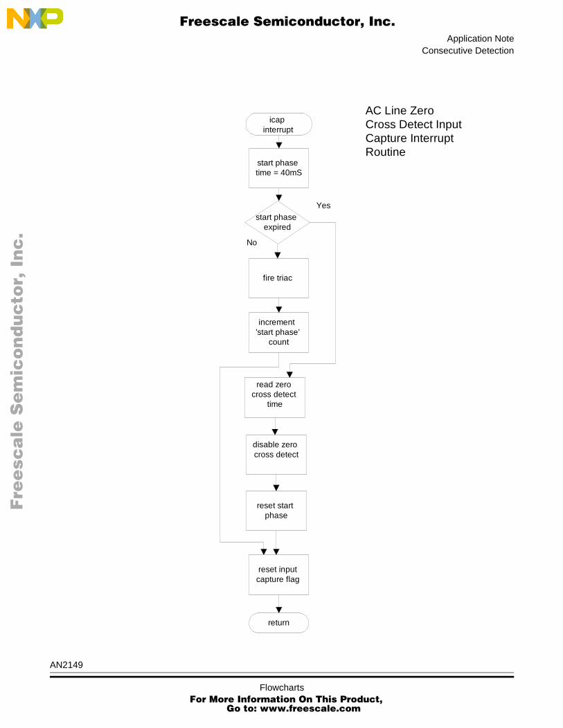
start phase time = 40mS
fire triac
disable zero cross detect
reset start phase
icap interrupt
AC Line Zero Cross Detect Input Capture Interrupt Routine
start phase expired
Yes
No
increment ’start phase’
count
reset input capture flag
return
read zero cross detect
time
AN2149
Flowcharts For More Information On This Product,
Go to: www.freescale.com

Application Note
F
ree
sca
le S
em
ico
nd
uc
tor,
I
Freescale Semiconductor, Inc.n
c..
.
motor stalldetect interruptStart WindingZero CrossDetect InterruptRoutine
return
Yes
No
clear ’motorstalled’ flag
increment startzero cross
count
is phaseshift valid
read start zerocross timefrom timer
calculatephase shift
reset phaseshift valid
count
is phase shift validcount = start zero
cross count
reset’consecutiveerror’ count
set ’motorstalled’ flag
No
Yes
are consecutivephase shift errors =
10
Yes
No
incrementconsecutiveerror count
Yes
increment’phase shiftvalid’ count
reset inputcapture flag
AN2149
14 Flowcharts For More Information On This Product,
Go to: www.freescale.com

Application NoteConsecutive Detection
F
ree
sca
le S
em
ico
nd
uc
tor,
I
Freescale Semiconductor, Inc.n
c..
.
4 Summary
There are many situations where it is convenient and sometimes necessary to have confirmation that the motor is in fact rotating when power is applied to the compressor. In the conventional arrangement the motor was protected from thermal damage by a bi-metallic contact. The Microcontroller can now manage this situation, decisions can be taken in the software based on the zero cross detection events of the run and start windings. In this way the motor can be protected from taking excessive power when in a stalled condition, therefore excessive winding temperature situations can be prevented from power-on. Additional thermal protection can also be included by connecting a sensor to the analogue to digital converter to continuously monitor motor temperature.
In applications that demand increased operational safety, knowing that the motor is rotating can be used as a comparative reference parameter for closed loop system integrity, safety measurements, or logic state confirmation checks. For example, in a pressurised system, if motor rotation is confirmed it can be expected that some time later the system should have achieved a specific pressure value. This can be measured using a pressure sensor and one of the analogue to digital converter inputs of the Microcontroller. Flow measurement can be achieved using a simple in-line switch connected to the device input/output ports. In these situations the Microcontroller can confirm motor rotation and compare with the feedback parameters measured within the software control loop.
Single-phase induction motors are widely used in ratings of 1hp and less, rarely greater than 10 hp. This power range of motors can meet the low through higher starting torque demands which are required for many household and industrial appliances, such as fans, which have a low starting torque and the higher starting torque demands of pumps, air conditioning units, and refrigeration compressors. As well as being a cost-effective solution, the adaptability and programmability of the Microcontroller can make a significant impact in the control, safety and efficiency of these and appliances.
AN2149
Summary For More Information On This Product,
Go to: www.freescale.com

Application Note
F
ree
sca
le S
em
ico
nd
uc
tor,
I
Freescale Semiconductor, Inc.n
c..
.
5 Code
During the initial start-up phase, the probability of a stall condition is higher. This typically can be caused by mechanical failure where the motor is unable to start due to an obstruction, or an electrical failure when the motor is unable to start due to internal winding damage or component failure. However, it may be convenient in some systems to extend this feature to monitor the rotation of the motor at any time during the normal operational cycle of the application. The following code has been structured such that functions can be included in the application and called at any time from power-on in a convenient way. A main routine is used to demonstrate the implementation of the code as described in the preceding flowcharts.
AN2149
16 Code For More Information On This Product,
Go to: www.freescale.com

Application NoteMain Routine
F
ree
sca
le S
em
ico
nd
uc
tor,
I
Freescale Semiconductor, Inc.n
c..
.
#include "hc08kx8.h" /* generic hc08kx8 header file*/#include "stall.h" /* application header file */
5.1 Main Routine
/******************************************************************************Copyright (c)
Function Name : main()
Engineer : William Mackay
Location : Freescale Microcontroller Division, East Kilbride
Date Created : March 2000
Current Revision : 0.0
Note : Main routine applies power to the motor, enablesor disables stall detection and powers the motordown based on the condition of a flag which iscontrolled in the stall detect ISR.
*******************************************************************************/
void main(void){
init();motor_on();while(1){
if(STALL_DETECT_SELECT == ENABLED) /* port pin high */{
stall_detect_enable(); /* enable stall detect input capture */if(motor_stalled) /* after start phase expired */{
motor_off(); /* remove power from motor */alarm_on(); /* audible alarm */
}}else{
stall_detect_disable();}
}}
AN2149
Code For More Information On This Product,
Go to: www.freescale.com

Application Note
F
ree
sca
le S
em
ico
nd
uc
tor,
I
Freescale Semiconductor, Inc.n
c..
.
5.2 Initialisation Routine
/******************************************************************************Copyright (c)
Function Name : init()
Engineer : William Mackay
Location : Freescale Microcontroller Division, East Kilbride
Date Created : March 2000
Current Revision : 0.0
Note : Function configures oscillator, device modulesand initialises application parameters
*******************************************************************************/
void init(void){
config(); /* sets configuration register */init_osc(); /* sets oscillator frequency */init_ports(); /* configure input/output ports */init_timer(); /* initialise timer */init_icap(); /* configure input capture pin */init_application(); /* initialises application parameters */
}
5.3 Configuration Routine
/******************************************************************************Copyright (c)
Function Name : config()
Engineer : William Mackay
Location : Freescale Microcontroller Division, East Kilbride
Date Created : March 2000
Current Revision : 0.0
Note : Function configures device configuration register
*******************************************************************************/
void config(){
CONFIG1= 0x31; /* disables lvi and cop */}
AN2149
18 Code For More Information On This Product,
Go to: www.freescale.com

Application NoteOscillator Initialisation Routine
F
ree
sca
le S
em
ico
nd
uc
tor,
I
Freescale Semiconductor, Inc.n
c..
.
5.4 Oscillator Initialisation Routine
/******************************************************************************Copyright (c)
Function Name : init_osc()
Engineer : William Mackay
Location : Freescale Microcontroller Division, East Kilbride
Date Created : March 2000
Current Revision : 0.0
Note : Function sets oscillator frequency
*******************************************************************************/
void init_osc(void){
ICGMR_N0 = SET; /* set oscillator frequency */ICGMR_N1 = RESET; /* multipier set for 29x307.2khz = 8.9Mhz */ICGMR_N2 = SET; /* = 2.27Mhz bus freq */ICGMR_N3 = SET;ICGMR_N4 = SET;ICGMR_N5 = RESET;ICGMR_N6 = RESET;
}
AN2149
Code For More Information On This Product,
Go to: www.freescale.com

Application Note
Function Name : init
Engineer : Will
Location : Free
Date Created : Marc
Current Revision : 0.0
Note : Conf
********************************
void init_ports(void){
DDRA_BIT0 = OUTPUT;DDRA_BIT1 = OUTPUT;DDRA_BIT4 = INPUT;PTAPUE_BIT4 = SET;
DDRB_BIT0 = INPUT;DDRB_BIT1 = INPUT;DDRB_BIT2 = INPUT;
DDRB_BIT3 = OUTPUT;DDRB_BIT6 = OUTPUT;DDRB_BIT5 = OUTPUT;DDRB_BIT4 = OUTPUT;
}
Fre
esc
ale
Se
mic
on
du
cto
r, I
Freescale Semiconductor, Inc.
F
nc
...
5.5 Initialise Input Output Ports Routine
/**************************************************************
_ports()
iam Mackay
scale Microcontroller Division, East Kilbride
h 2000
igures input output ports
***********************************************/
/* relay *//* buzzer *//* door *//* enable pull-up */
/* UPDATE check adc init air temp adc *//* evaporator temp adc *//* temp select */
/* yellow motor ’on’ led *//* triac drive *//* power ’on’ red led *//* alarm on-green led */
AN2149
20 Code or More Information On This Product,
Go to: www.freescale.com

Application NoteTimer Initialisation Routine
F
ree
sca
le S
em
ico
nd
uc
tor,
I
Freescale Semiconductor, Inc.n
c..
.
5.6 Timer Initialisation Routine
/******************************************************************************Copyright (c)
Function Name : init_timer()
Engineer : William Mackay
Location : Freescale Microcontroller Division, East Kilbride
Date Created : March 2000
Current Revision : 0.0
Note : Function used to configure timer interface module.Sets internal bus clock pre-scalar for timer counter
*******************************************************************************/
void init_timer(void){
TSC = RESET; /* internal bus clock divide by 1 */}
AN2149
Code For More Information On This Product,
Go to: www.freescale.com

Application Note
F
ree
sca
le S
em
ico
nd
uc
tor,
I
Freescale Semiconductor, Inc.n
c..
.
5.7 Input Capture Initialisation Routine
/******************************************************************************Copyright (c)
Function Name : init_icap()
Engineer : William Mackay
Location : Freescale Microcontroller Division, East Kilbride
Date Created : March 2000
Current Revision : 0.0
Note : This function configures timer channel zero andChannel 1 as input capture for rising and falling edgedetection
*******************************************************************************/
void init_icap(void){
TSC_TSTOP = RESET; /* start timer */TSC0_MS0A = RESET; /* mode select = input capture */TSC0_MS0B = RESET;TSC0_ELS0A = SET; /* capture on rising or falling edge */TSC0_ELS0B = SET;TSC0_CH0IE = RESET; /* enable interrupts */
TSC1_MS1A = RESET; /* mode select = input capture */TSC1_ELS1A = SET; /* capture on rising or falling edge */TSC1_ELS1B = SET;TSC1_CH1F = RESET; /* clear flag*/TSC1_CH1IE = SET; /* enable interrupts */
}
AN2149
22 Code For More Information On This Product,
Go to: www.freescale.com

Application NoteInitialise Application Routine
F
ree
sca
le S
em
ico
nd
uc
tor,
I
Freescale Semiconductor, Inc.n
c..
.
5.8 Initialise Application Routine
/******************************************************************************Copyright (c)
Function Name : init_application()
Engineer : William Mackay
Location : Freescale Microcontroller Division, East Kilbride
Date Created : March 2000
Current Revision : 0.0
Note : Function initialises application parameters
*******************************************************************************/
void init_application(){
POWER_STATUS = ON; /* red led */MOTOR_POWER = DISABLED; /* motor relay de-energised */MOTOR_STATUS = OFF; /* green led */TRIAC_DRIVE = DISABLED; /* triac off */BUZZER = OFF;ALARM_STATUS = OFF; /* yellow led */ZERO_CROSS_DETECT = ENABLED; /* start motor at next zero cross */stall_detect_disable(); /* enable stall detect input capture */ENABLE_INTERRUPTS; /* enable interrupts */
}
5.9 Motor ‘on’ Routine
/******************************************************************************Copyright (c)
Function Name : motor_on()
Engineer : William Mackay
Location : Freescale Microcontroller Division, East Kilbride
Date Created : March 2000
Current Revision : 0.0
Note : Function powers-on motor
*******************************************************************************/ void motor_on(void){
MOTOR_POWER = ENABLED; /* motor relay energised */MOTOR_STATUS = ON;
}
AN2149
Code For More Information On This Product,
Go to: www.freescale.com

Application Note
F
ree
sca
le S
em
ico
nd
uc
tor,
I
Freescale Semiconductor, Inc.n
c..
.
5.10 Stall Detect Enable Routine
/******************************************************************************Copyright (c)
Function Name : stall_detect_enable()
Engineer : William Mackay
Location : Freescale Microcontroller Division, East Kilbride
Date Created : March 2000
Current Revision : 0.0
Note : Enables stall detection
*******************************************************************************/
void stall_detect_enable(){
if(start_phase == RESET /* initial motor start phase complete */{
MOTOR_STALL_DETECT = ENABLED; }}
5.11 Motor ‘off’ Routine
/******************************************************************************Copyright (c)
Function Name : motor_off()
Engineer : William Mackay
Location : Freescale Microcontroller Division, East Kilbride
Date Created : March 2000
Current Revision : 0.0
Note : Function powers-down motor
*******************************************************************************/
void motor_off(void){
MOTOR_POWER = DISABLED; /* motor relay de-energised */ZERO_CROSS_DETECT = DISABLED; /* disable icap interrupt */MOTOR_STATUS = OFF; /* motor led */
}
AN2149
24 Code For More Information On This Product,
Go to: www.freescale.com

Application NoteAlarm ‘on’ Routine
F
ree
sca
le S
em
ico
nd
uc
tor,
I
Freescale Semiconductor, Inc.n
c..
.
5.12 Alarm ‘on’ Routine
/******************************************************************************Copyright (c)
Function Name : alarm_on()
Engineer : William Mackay
Location : Freescale Microcontroller Division, East Kilbride
Date Created : March 2000
Current Revision : 0.0
Note : Function invokes alarm status and audible alarm
*******************************************************************************/
void alarm_on(void){
ALARM_STATUS = ON;BUZZER = ON;
}
5.13 Stall Detect Disable Routine
/******************************************************************************Copyright (c)
Function Name : stall_detect_disable()
Engineer : William Mackay
Location : Freescale Microcontroller Division, East Kilbride
Date Created : March 2000
Current Revision : 0.0
Note : Disables stall detection
*******************************************************************************/
void stall_detect_disable(){
if(start_phase == RESET) /* initial motor start phase complete */{
MOTOR_STALL_DETECT = DISABLED; }}
AN2149
Code For More Information On This Product,
Go to: www.freescale.com

Application Note
F
ree
sca
le S
em
ico
nd
uc
tor,
I
Freescale Semiconductor, Inc.n
c..
.
5.14 Delay Routine
/******************************************************************************Copyright (c)
Function Name : delay()
Engineer : William Mackay
Location : Freescale Microcontroller Division, East Kilbride
Date Created : March 2000
Current Revision : 0.0
Note : This delay for triac pulse period
*******************************************************************************/
void delay(void){
unsigned char i,j;for(i=0; i<2; i++){
for(j=0; j<1; j++);}
}
AN2149
26 Code For More Information On This Product,
Go to: www.freescale.com

Application NoteInput Capture Routine
F
ree
sca
le S
em
ico
nd
uc
tor,
I
Freescale Semiconductor, Inc.n
c..
.
5.15 Input Capture Routine
/*****************************************************************************Copyright (c)
Function Name : input_capture()
Engineer : William Mackay
Location : Freescale Microcontroller Division, East Kilbride
Date Created : March 2000
Current Revision : 0.0
Note : This ISR pulses the triac when line voltage zero-crossIs detected, for a pre-defined motor start period
*******************************************************************************/
#pragma TRAP_PROC SAVE_REGSvoid Input_Capture(void){
if(start_phase != START_TIME /* start phase valid */{
TRIAC_DRIVE = OFF; /* apply pulse to triac */delay();TRIAC_DRIVE = ON; ++start_phase; /* start phase is a count of the */
} /* line voltage zero cross points */else{ /* start time has expired */
timer_ch0.count.timer_high = TIMER_CH0_HIGH; /* read high byte of counter */timer_ch0.count.timer_low = TIMER_CH0_LOW; /* read low byte of counter */ZERO_CROSS_DETECT = DISABLED; /* disable timer ch 0 icap interrupt */MOTOR_STALL_DETECT = ENABLED; /* enable timer ch1 icap interrupt */start_phase = RESET; /* reset start phase */
}read_register = TSC0; /* reads TIM status and control regr */ICAP0_FLAG = RESET; /* resets CH0F flag */
}
AN2149
Code For More Information On This Product,
Go to: www.freescale.com

Application Note
F
ree
sca
le S
em
ico
nd
uc
tor,
I
Freescale Semiconductor, Inc.n
c..
.
5.16 Stall Detection Routine
/******************************************************************************Copyright (c)
Function Name : stall_detect()
Engineer : William Mackay
Location : Freescale Microcontroller Division, East Kilbride
Date Created : March 2000
Current Revision : 0.0
Note : This ISR detects the induced voltage in the motorstart winding after the initial start phase has expired.
*******************************************************************************/
#pragma TRAP_PROC SAVE_REGSvoid Stall_Detect(void){
timer_ch1.count.timer_high = TIMER_CH1_HIGH; /* read high byte of counter */timer_ch1.count.timer_low = TIMER_CH1_LOW; /* read low byte of counter */++start_zero_cross; /* cumulative count of start zero cross points */ if(timer_ch1.timer_count > timer_ch0.timer_count){
phase_shift = (timer_ch1.timer_count - timer_ch0.timer_count);}else{
phase_shift = (TIMER_COUNT_MAX - timer_ch0.timer_count + timer_ch1.timer_count)} /*accomodates counter rollover */if((timer_ch1.timer_count >= (timer_ch0.timer_count + phase_shift - PHASE_MIN))&&(timer_ch1.timer_count <= (timer_ch0.timer_count + phase_shift + PHASE_MAX))){ /* checks phase shift tolerance */
++phase_shift_valid; /* cumulative count of valid phase shifts */} /* each zero cross should have a valid phase shift */else{
phase_shift_valid = RESET;}if(phase_shift_valid != start_zero_cross) /* both counts are not the same */{
++consecutive_error; /* cumulative count of phase shift errors */}else{
consecutive_error = RESET;}if(consecutive_error >= PHASE_ERROR_COUNT_MAX){
motor_stalled = SET; /* indicates motor has stalled */}else{
motor_stalled = RESET; /* motor is rotating */}read_register = TSC1; /* reads TIM status and control regr */ICAP1_FLAG = RESET; /* resets CH1F flag */
}
AN2149
28 Code For More Information On This Product,
Go to: www.freescale.com

Application NoteHC08KX8 Generic Header File
F
ree
sca
le S
em
ico
nd
uc
tor,
I
Freescale Semiconductor, Inc.n
c..
.
5.17 HC08KX8 Generic Header File
/******************************************************************************Copyright (c)
File Name : HC08KX8.h
Org Author : William Mackay
Location : Freescale Microcontroller Division, East Kilbride
Date Created : December 1999
Current Revision : 0.0
Notes : This file maps the 68HC908KX8 register set as defined in the General Release Specification.
*******************************************************************************/
#ifndef _HC08KX8_H#define _HC08KX8_H
/****************************************************************************//* Register Mapping Structures and Macros *//****************************************************************************/
#define REGISTER(a) (*((volatile unsigned char *)(a)))#define BIT(a,b) (((vbitfield *)(a))->bit##b)
/* assumes right to left bit order */
typedef volatile struct{volatile unsigned int bit0 : 1;volatile unsigned int bit1 : 1;volatile unsigned int bit2 : 1;volatile unsigned int bit3 : 1;volatile unsigned int bit4 : 1;volatile unsigned int bit5 : 1;volatile unsigned int bit6 : 1;volatile unsigned int bit7 : 1;
} vbitfield;
typedef union{
struct{unsigned char timer_high;unsigned char timer_low;
} count;unsigned short timer_count;
}TIMER;
TIMER timer_ch0;TIMER timer_ch1;
AN2149
Code For More Information On This Product,
Go to: www.freescale.com
Application Note
F
ree
sca
le S
em
ico
nd
uc
tor,
I
Freescale Semiconductor, Inc.n
c..
.
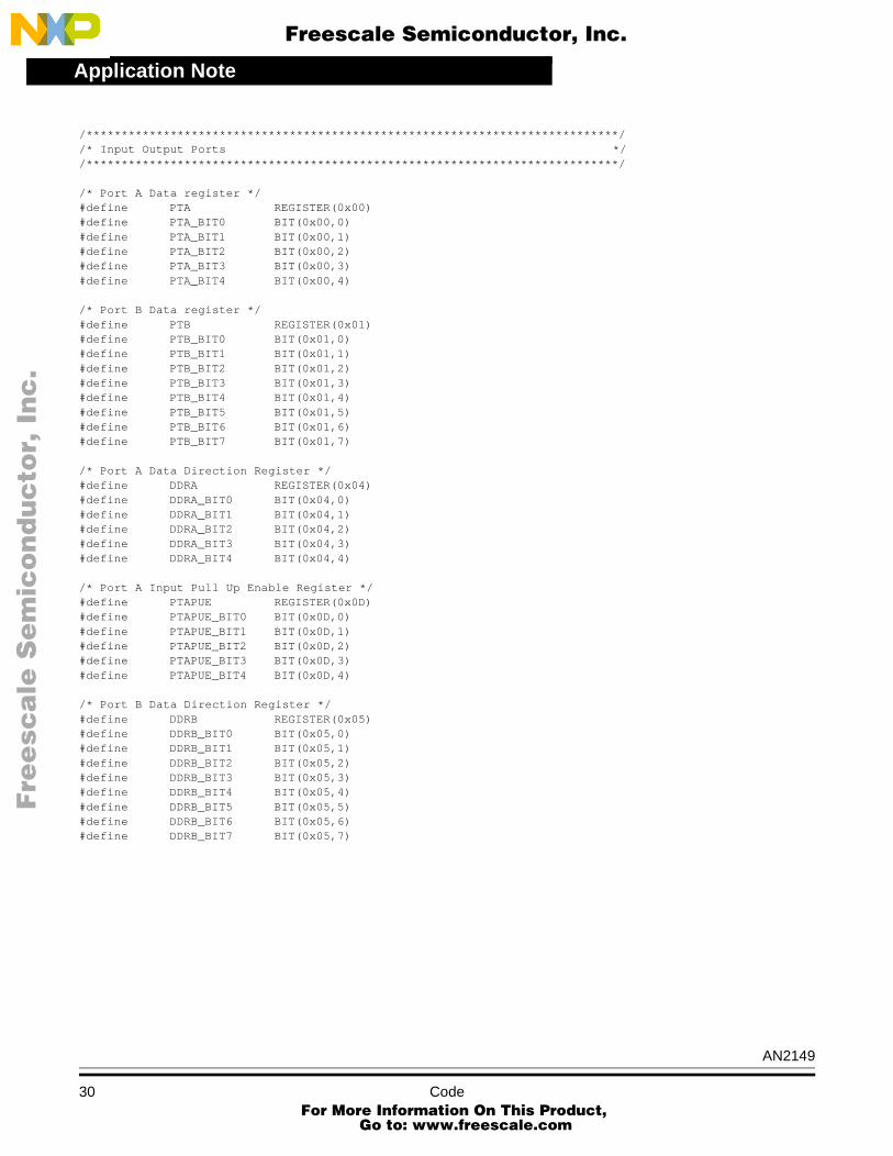
/****************************************************************************//* Input Output Ports *//****************************************************************************/ /* Port A Data register */#define PTA REGISTER(0x00)#define PTA_BIT0 BIT(0x00,0)#define PTA_BIT1 BIT(0x00,1)#define PTA_BIT2 BIT(0x00,2)#define PTA_BIT3 BIT(0x00,3)#define PTA_BIT4 BIT(0x00,4)
/* Port B Data register */#define PTB REGISTER(0x01)#define PTB_BIT0 BIT(0x01,0)#define PTB_BIT1 BIT(0x01,1)#define PTB_BIT2 BIT(0x01,2)#define PTB_BIT3 BIT(0x01,3)#define PTB_BIT4 BIT(0x01,4)#define PTB_BIT5 BIT(0x01,5)#define PTB_BIT6 BIT(0x01,6)#define PTB_BIT7 BIT(0x01,7)
/* Port A Data Direction Register */#define DDRA REGISTER(0x04)#define DDRA_BIT0 BIT(0x04,0)#define DDRA_BIT1 BIT(0x04,1)#define DDRA_BIT2 BIT(0x04,2)#define DDRA_BIT3 BIT(0x04,3)#define DDRA_BIT4 BIT(0x04,4)
/* Port A Input Pull Up Enable Register */#define PTAPUE REGISTER(0x0D)#define PTAPUE_BIT0 BIT(0x0D,0)#define PTAPUE_BIT1 BIT(0x0D,1)#define PTAPUE_BIT2 BIT(0x0D,2)#define PTAPUE_BIT3 BIT(0x0D,3)#define PTAPUE_BIT4 BIT(0x0D,4)
/* Port B Data Direction Register */#define DDRB REGISTER(0x05)#define DDRB_BIT0 BIT(0x05,0)#define DDRB_BIT1 BIT(0x05,1)#define DDRB_BIT2 BIT(0x05,2)#define DDRB_BIT3 BIT(0x05,3)#define DDRB_BIT4 BIT(0x05,4)#define DDRB_BIT5 BIT(0x05,5)#define DDRB_BIT6 BIT(0x05,6)#define DDRB_BIT7 BIT(0x05,7)
AN2149
30 Code For More Information On This Product,
Go to: www.freescale.com

Application NoteHC08KX8 Generic Header File
F
ree
sca
le S
em
ico
nd
uc
tor,
I
Freescale Semiconductor, Inc.n
c..
.
/****************************************************************************//* Time Base Register *//****************************************************************************/
#define TBCR REGISTER(0x1C)#define TBCR_TBON BIT(0x1C,1)#define TBCR_TBIE BIT(0x1C,2)#define TBCR_TACK BIT(0x1C,3)#define TBCR_TBR0 BIT(0x1C,4)#define TBCR_TBR1 BIT(0x1C,5)#define TBCR_TBR2 BIT(0x1C,6)#define TBCR_TBIF BIT(0x1C,7)
/****************************************************************************//* Configuration Write-Once Registers *//****************************************************************************/
#define CONFIG2 REGISTER(0x1e)#define CONFIG1 REGISTER(0x1F)
/****************************************************************************//* Timer Registers *//****************************************************************************/
/* Timer Status and Control Register */#define TSC REGISTER(0x20)#define TSC_PS0 BIT(0x20,0)#define TSC_PS1 BIT(0x20,1)#define TSC_PS2 BIT(0x20,2)#define TSC_TRST BIT(0x20,4)#define TSC_TSTOP BIT(0x20,5)#define TSC_TOIE BIT(0x20,6)#define TSC_TOF BIT(0x20,7)
/* Timer Counter Register */#define TCNTH REGISTER(0x21)#define TCNTL REGISTER(0x22)
/* Timer Modulo Register */#define TMODH REGISTER(0x23)#define TMODL REGISTER(0x24)
/* Timer Status and Control Register Channel 0 */#define TSC0 REGISTER(0x25)#define TSC0_CH0MAX BIT(0x25,0)#define TSC0_TOV0 BIT(0x25,1)#define TSC0_ELS0A BIT(0x25,2)#define TSC0_ELS0B BIT(0x25,3)#define TSC0_MS0A BIT(0x25,4)#define TSC0_MS0B BIT(0x25,5)#define TSC0_CH0IE BIT(0x25,6)#define TSC0_CH0F BIT(0x25,7)
AN2149
Code For More Information On This Product,
Go to: www.freescale.com

Application Note
F
ree
sca
le S
em
ico
nd
uc
tor,
I
Freescale Semiconductor, Inc.n
c..
.
/* Timer Channel 0 Register */#define TCH0H REGISTER(0x26)#define TCH0L REGISTER(0x27)
/* Timer Status and Control Register Channel 1 */#define TSC1 REGISTER(0x28)#define TSC1_CH1MAX BIT(0x28,0)#define TSC1_TOV1 BIT(0x28,1)#define TSC1_ELS1A BIT(0x28,2)#define TSC1_ELS1B BIT(0x28,3)#define TSC1_MS1A BIT(0x28,4)#define TSC1_CH1IE BIT(0x28,6)#define TSC1_CH1F BIT(0x28,7)
/* Timer Channel 1 Register */#define TCH1H REGISTER(0x29)#define TCH1L REGISTER(0x2a)
/****************************************************************************//* ICG Registers *//****************************************************************************/
/* ICG Control Register */#define ICGCR REGISTER(0x36)#define ICGCR_ECGS BIT(0x36,0)#define ICGCR_ECGON BIT(0x36,1)#define ICGCR_ICGS BIT(0x36,2)#define ICGCR_ICGON BIT(0x36,3)#define ICGCR_CS BIT(0x36,4)#define ICGCR_CMON BIT(0x36,5)#define ICGCR_CMF BIT(0x36,6)#define ICGCR_CMIE BIT(0x36,7)
/* ICG Multiply Register */#define ICGMR REGISTER(0x37)#define ICGMR_N0 BIT(0x37,0)#define ICGMR_N1 BIT(0x37,1)#define ICGMR_N2 BIT(0x37,2)#define ICGMR_N3 BIT(0x37,3)#define ICGMR_N4 BIT(0x37,4)#define ICGMR_N5 BIT(0x37,5)#define ICGMR_N6 BIT(0x37,6)
/* ICG Trim Register */#define ICGTR REGISTER(0x38)#define ICGTR_TRIM0 BIT(0x38,0)#define ICGTR_TRIM1 BIT(0x38,1)#define ICGTR_TRIM2 BIT(0x38,2)#define ICGTR_TRIM3 BIT(0x38,3)#define ICGTR_TRIM4 BIT(0x38,4)#define ICGTR_TRIM5 BIT(0x38,5)#define ICGTR_TRIM6 BIT(0x38,6)#define ICGTR_TRIM7 BIT(0x38,7)
/****************************************************************************//* Analogue To Digital Converter Registers *//****************************************************************************/
/* A/D Status and Control Register */
AN2149
32 Code For More Information On This Product,
Go to: www.freescale.com

Application NoteHC08KX8 Generic Header File
F
ree
sca
le S
em
ico
nd
uc
tor,
I
Freescale Semiconductor, Inc.n
c..
.
#define ADSCR REGISTER(0x3c)#define ADSCR_ADCH0 BIT(0x3c,0)#define ADSCR_ADCH1 BIT(0x3c,1)#define ADSCR_ADCH2 BIT(0x3c,2)#define ADSCR_ADCH3 BIT(0x3c,3)#define ADSCR_ADCH4 BIT(0x3c,4)#define ADSCR_ADCO BIT(0x3c,5)#define ADSCR_AIEN BIT(0x3c,6)#define ADSCR_COCO BIT(0x3c,7)
/* A/D-Data Register */#define ADR REGISTER(0x3d)
/* A/D Input Clock Register */#define ADCLK REGISTER(0x3e)#define ADCLK_ADICLK BIT(0x3e,4)#define ADCLK_ADIV0 BIT(0x3e,5)#define ADCLK_ADIV1 BIT(0x3e,6)#define ADCLK_ADIV2 BIT(0x3e,7)
/****************************************************************************//* Low Voltage Inhibit Register *//****************************************************************************/
/* LVI Status Register */#define LVISR REGISTER(0xFE0C)#define LVISR_LVIOUT BIT(0xFE0C,7) #endif
AN2149
Code For More Information On This Product,
Go to: www.freescale.com

Application Note
F
ree
sca
le S
em
ico
nd
uc
tor,
I
Freescale Semiconductor, Inc.n
c..
.
5.18 Application Header File
/******************************************************************************Copyright (c)
File Name : StallDetect.h
Engineer : William Mackay
Location : Freescale Microcontroller Division, East Kilbride
Date Created : March 2000
Current Revision : 0.0
Notes : This file contains application definitions
*******************************************************************************/
#ifndef _STALL_H#define _STALL_H
/****************************************************************************//* Constant Definitions *//****************************************************************************/
#define ON 0#define OFF 1#define SET 1#define RESET 0#define ENABLED 1#define DISABLED 0#define RESET 0#define OUTPUT 1#define INPUT 0
#define START_TIME 0x28 /* motor start-up period (40mS) */#define STALL_PERIOD 0xFF /* 255x10mS = 2.55Sec 0x07 motor stall time period (3 cycles) */#define TIMER_COUNT_MAX 0xFFFF /* maximum value of timer counter */#define PHASE_MIN 0x0D50 /* 3408 */#define PHASE_MAX 0x0470 /* 1136 */#define PHASE_ERROR_COUNT_MAX 0x06
/****************************************************************************//* Input/Output Port Application Definitions *//****************************************************************************/
#define MOTOR_POWER PTA_BIT0#define BUZZER PTA_BIT1#define STALL_DETECT_SELECT PTA_BIT4#define TRIAC_DRIVE PTB_BIT6#define POWER_STATUS PTB_BIT5#define MOTOR_STATUS PTB_BIT3#define ALARM_STATUS PTB_BIT4
AN2149
34 Code For More Information On This Product,
Go to: www.freescale.com

Application NoteApplication Header File
F
ree
sca
le S
em
ico
nd
uc
tor,
I
Freescale Semiconductor, Inc.n
c..
.
/****************************************************************************//* Timer *//****************************************************************************/
#define ZERO_CROSS_DETECT TSC0_CH0IE#define ICAP0_FLAG TSC0_CH0F#define MOTOR_STALL_DETECT TSC1_CH1IE#define ICAP1_FLAG TSC1_CH1F#define TIMER_CH0_HIGH TCH0H#define TIMER_CH0_LOW TCH0L#define TIMER_CH1_HIGH TCH1H#define TIMER_CH1_LOW TCH1L
/****************************************************************************//* Function Prototypes *//****************************************************************************/
void main(void);void config(void);void init(void);void init_ports(void);void init_osc(void);void init_timer(void);void init_icap(void);void init_application(void);void delay(void);void stall_detect_enable(void);void stall_detect_disable();void motor_on(void);void motor_off(void);void power_down(void);void alarm_on(void);void Input_Capture(void);void Stall_Detect(void);
/****************************************************************************//* Global Variables *//****************************************************************************/
/* Zero Page RAM variables */#pragma DATA_SEG _DATA_ZEROPAGEunsigned char start_phase; /* indicates status of start time interval */unsigned char motor_stalled; /* indicates motor start status */unsigned char stall_time; /* count for permitted stall time */unsigned char read_register; /* dummy read locatin for flag clearing */unsigned char start_zero_cross; /* count */unsigned int phase_shift; /* time storage */unsigned char phase_shift_valid; /* count */unsigned char consecutive_error; /* count *//****************************************************************************//* Interrupt Definitions *//****************************************************************************/
#define ENABLE_INTERRUPTS asm cli;#define DISABLE_INTERRUPTS asm sei;
#endif
AN2149
Code For More Information On This Product,
Go to: www.freescale.com

N
ON
-D
IS
CL
OS
UR
E
AG
RE
EM
EN
T
RE
QU
IR
ED
Application Note
F
ree
sca
le S
em
ico
nd
uc
tor,
I
Freescale Semiconductor, Inc.n
c..
.
For More Information On This Product, Go to: www.freescale.com


![34178 - NASA · suppress rotating stall and surge: Paduand[ref.(9)] used "wiggling" inlet guide vanes to control rotating stall in the axial compressor andFfowcs Williams [ref.(10)]](https://img.pdfslide.net/doc/110x75/5e8e40089421c9008740a043/34178-nasa-suppress-rotating-stall-and-surge-paduandref9-used-wiggling.jpg)