Embed Size (px)
Citation preview

8/12/2019 AN22 Modulating Laser Diode IX
http://slidepdf.com/reader/full/an22-modulating-laser-diode-ix 1/9
#22 Modulating Laser Diode
8/12/2019 AN22 Modulating Laser Diode IX
http://slidepdf.com/reader/full/an22-modulating-laser-diode-ix 2/9
Introduction
The external modulation feature found onmany ILX Lightwave current sources is a veryexible circuit that can be used for a widevariety of applications. If the task is to slightlydither the current to produce laser linewidth
broadening or wavelength control, small signalanalog modulation is easily possible. If thetask requires the laser output to be amplitude-modulated at audio frequencies or higher, itcan still be easily done by directly modulatingthe current source. If a digital style of pulse isrequired where the leading and trailing edgesare sharp and discontinuous, modulation of thecurrent source may still be acceptable. Theacceptance criteria for this type of modulationcenters around the level of ringing in the outputthat can be tolerated. Careful consideration ofthe modulation test parameters and instrumentspecications will help determine if a bulky biastee network can be eliminated from the setup
and replaced with a laser controller that mostlikely is already sitting on a shelf or integratedinto the test in the lab.
Current sources capable of direct modulationwill typically have smaller bandwidths thanbias tees because the larger the bandwidthof the current source, the more inherentnoise in the output. Even with this limitation,these modulation-capable current sourcesare more exible in their usage. Any laserthat is connected to the current source maybe modulated. In contrast, only lasers with
i i i ti b d i
Modulating Laser Diodes
reasons why direct modulation osource may be preferred.
Test Setup
Throughout this discussion, traces will be presented to help ex
aspects of laser modulation. Twere generated using an ILX Ligh3724B laser diode controller assource and viewed with a Tektronoscilloscope. The output was moan Agilent 33120A function geNEL NLK1556STG DFB laser the LDC-3724B via a standardbuttery laser mount was the omodulation. The laser output won the scope using a ThorLaphotodetector set to its widestIn order to drive the current sofull range, a JDS-Fitel HA1 opticwas used to prevent detector satu
values of laser current.
Conguring a Current Source forModulation
Each ILX Lightwave current soof being modulated externally hfunction corresponding to each curange. In most cases, the transwill be displayed on the instrumenthe input connector. These transfin units of milliamps per volt (mthe input signal required to produ
F l h 2
8/12/2019 AN22 Modulating Laser Diode IX
http://slidepdf.com/reader/full/an22-modulating-laser-diode-ix 3/9
current setpoint. In the present example, if thesetpoint were 100mA, the total output would be120mA. If instead the output is modulated witha 1kHz sine wave centered on 0V, the outputwill be sinusoidally modulated at 1kHz with amaximum output of 120mA and a minimumoutput of 80mA.
Along with the transfer function, the modulationcircuit is specied by an input impedancevalue. This impedance will be in the rangeof 50 to 10k Ω, depending on the instrument.Refer to the instrument’s documentation forthis specication. This impedance is importantwhen setting modulation voltage levels. If theinput impedance is low, the function generatorsignal will typically be signicantly loadeddown when connected and cause the outputto be different from what is expected. It is bestto set the modulation levels with the functiongenerator output connected to the modulationinput with the laser output disabled. This way,
the circuit will be properly loaded, and there willbe no risk of damage to the laser from beingoverdriven.
High Frequency Rolloff & BandwidthDetermination
Most ILX Lightwave laser current sources havea low bandwidth (CW) and a high bandwidthoutput mode. As described earlier, the lowbandwidth mode is designed for very low noiseCW output and is typically inappropriate for usewith external modulation. The high bandwidth
d th th h d id h
impedence, the nal piece of infospecies the external modulatioan ILX current source is its banbandwidth is the frequency range supported without having a signiin the output and is dependent onmethod. Modulation method m
analog or digital. Analog modumeans the waveform is continuousamplitude. A sine wave is a perfeDigital modulation, on the other ha discontinuous change in amsquare wave is the prime exampmodulation.
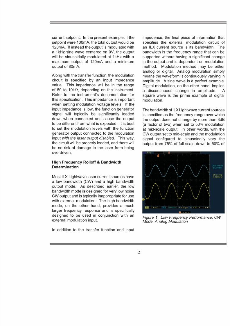
The bandwidth of ILX Lightwave cuis specied as the frequency rangethe output does not change by mo(a factor of two) when set to 50%at mid-scale output. In other woCW output set to mid-scale and thesignal congured to sinusoidal
output from 75% of full scale dow
8/12/2019 AN22 Modulating Laser Diode IX
http://slidepdf.com/reader/full/an22-modulating-laser-diode-ix 4/9
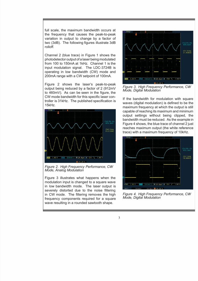
full scale, the maximum bandwidth occurs atthe frequency that causes the peak-to-peakvariation in output to change by a factor oftwo (3dB). The following gures illustrate 3dBrolloff.
Channel 2 (blue trace) in Figure 1 shows thephotodetector output of a laser being modulatedfrom 100 to 150mA at 1kHz. Channel 1 is theinput modulation signal. The LDC-3724B isoperating in low bandwidth (CW) mode and200mA range with a CW setpoint of 100mA .
Figure 2 shows the laser’s peak-to-peakoutput being reduced by a factor of 2 (912mV
to 460mV). As can be seen in the gure, theCW mode bandwidth for this specic laser con-troller is 31kHz. The published specication is15kHz.
Figure 2. High Frequency Performance, CWMode, Analog Modulation
Figure 3. High Frequency PerformMode, Digital Modulation
If the bandwidth for modulationwaves (digital modulation) is denmaximum frequency at which the capable of reaching its maximum anoutput settings without being bandwidth must be reduced. As the
Figure 4 shows, the blue trace of chreaches maximum output (the whitrace) with a maximum frequency
8/12/2019 AN22 Modulating Laser Diode IX
http://slidepdf.com/reader/full/an22-modulating-laser-diode-ix 5/9Figure 7. High Frequency ResponHigh Bandwidth Mode Overdriven
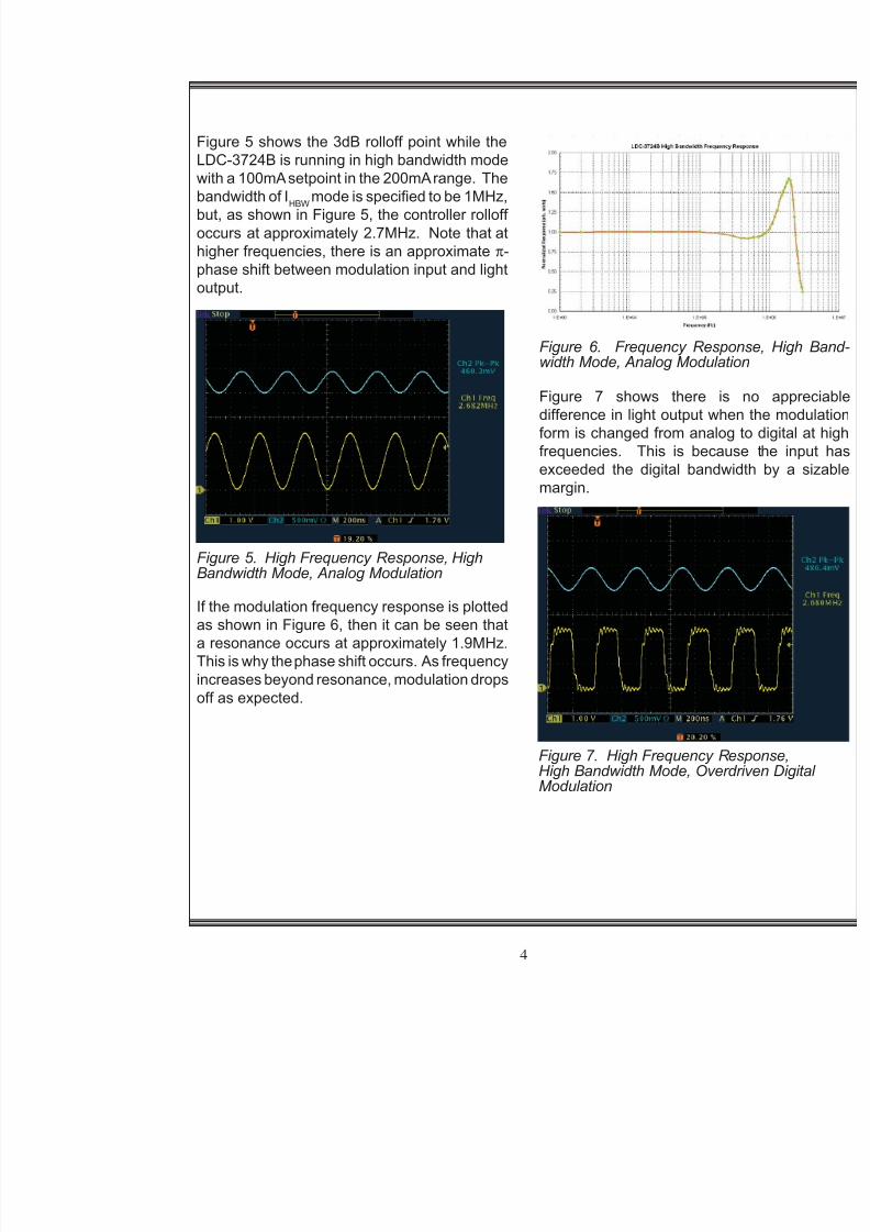
Figure 5 shows the 3dB rolloff point while theLDC-3724B is running in high bandwidth modewith a 100mA setpoint in the 200mA range. Thebandwidth of I HBW mode is specied to be 1MHz,but, as shown in Figure 5, the controller rolloffoccurs at approximately 2.7MHz. Note that athigher frequencies, there is an approximate π -
phase shift between modulation input and lightoutput.
If the modulation frequency response is plottedas shown in Figure 6, then it can be seen thata resonance occurs at approximately 1.9MHz.This is why the phase shift occurs. As frequency
increases beyond resonance, modulation dropsoff as expected.
Figure 5. High Frequency Response, HighBandwidth Mode, Analog Modulation
Figure 6. Frequency Response, width Mode, Analog Modulation
Figure 7 shows there is no difference in light output when thform is changed from analog to dfrequencies. This is because thexceeded the digital bandwidth bmargin.
8/12/2019 AN22 Modulating Laser Diode IX
http://slidepdf.com/reader/full/an22-modulating-laser-diode-ix 6/9Pulsed Operation
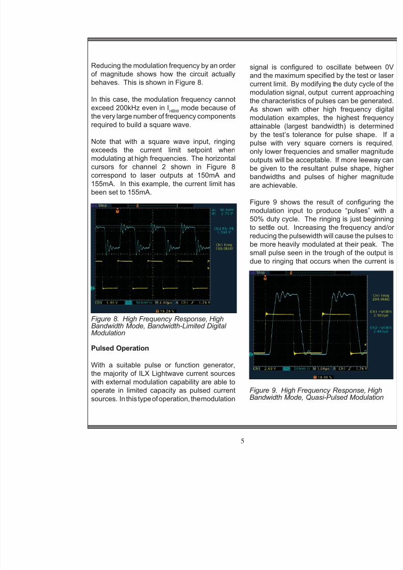
Figure 8. High Frequency Response, HighBandwidth Mode, Bandwidth-Limited DigitalModulation
signal is congured to oscillate and the maximum specied by the current limit. By modifying the dumodulation signal, output current the characteristics of pulses can be
As shown with other high freqmodulation examples, the highes
attainable (largest bandwidth) isby the test’s tolerance for pulse pulse with very square corners only lower frequencies and smalleoutputs will be acceptable. If morebe given to the resultant pulse shbandwidths and pulses of higheare achievable.
Figure 9 shows the result of conmodulation input to produce “pu50% duty cycle. The ringing is jto settle out. Increasing the frequreducing the pulsewidth will cause be more heavily modulated at thei
small pulse seen in the trough of tdue to ringing that occurs when th
Reducing the modulation frequency by an orderof magnitude shows how the circuit actuallybehaves. This is shown in Figure 8.
In this case, the modulation frequency cannotexceed 200kHz even in I HBW mode because ofthe very large number of frequency components
required to build a square wave.
Note that with a square wave input, ringingexceeds the current limit setpoint whenmodulating at high frequencies. The horizontalcursors for channel 2 shown in Figure 8correspond to laser outputs at 150mA and155mA. In this example, the current limit hasbeen set to 155mA.
8/12/2019 AN22 Modulating Laser Diode IX
http://slidepdf.com/reader/full/an22-modulating-laser-diode-ix 7/9
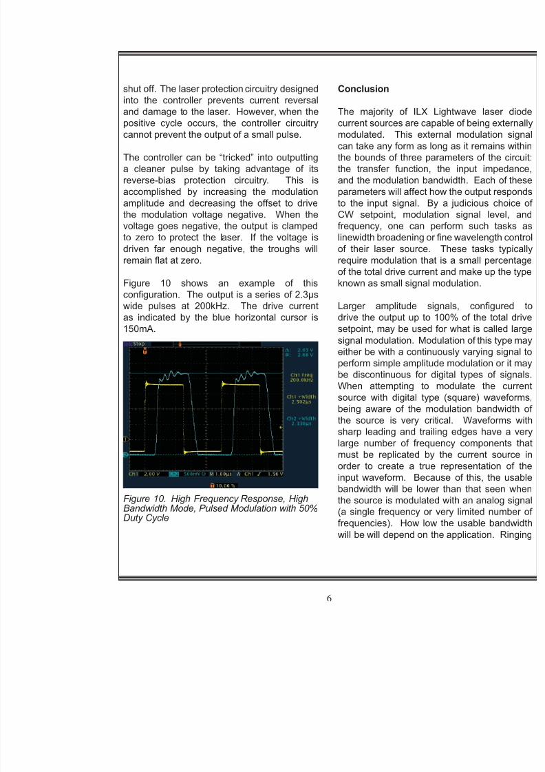
shut off. The laser protection circuitry designedinto the controller prevents current reversaland damage to the laser. However, when thepositive cycle occurs, the controller circuitrycannot prevent the output of a small pulse.
The controller can be “tricked” into outputting
a cleaner pulse by taking advantage of itsreverse-bias protection circuitry. This isaccomplished by increasing the modulationamplitude and decreasing the offset to drivethe modulation voltage negative. When thevoltage goes negative, the output is clampedto zero to protect the laser. If the voltage isdriven far enough negative, the troughs willremain at at zero.
Figure 10 shows an example of thisconguration. The output is a series of 2.3µswide pulses at 200kHz. The drive currentas indicated by the blue horizontal cursor is150mA.
Conclusion
The majority of ILX Lightwavcurrent sources are capable of beinmodulated. This external moducan take any form as long as it remthe bounds of three parameters of
the transfer function, the input and the modulation bandwidth. Eparameters will affect how the outpto the input signal. By a judicioCW setpoint, modulation signafrequency, one can perform suclinewidth broadening or ne wavelof their laser source. These tasrequire modulation that is a smallof the total drive current and makeknown as small signal modulation
Larger amplitude signals, codrive the output up to 100% of thsetpoint, may be used for what is
signal modulation. Modulation of either be with a continuously varyperform simple amplitude modulatbe discontinuous for digital typeWhen attempting to modulate source with digital type (square)being aware of the modulation bthe source is very critical. Wavsharp leading and trailing edges large number of frequency compmust be replicated by the currenorder to create a true representainput waveform. Because of this

8/12/2019 AN22 Modulating Laser Diode IX
http://slidepdf.com/reader/full/an22-modulating-laser-diode-ix 8/9
will be very evident at high frequencies, and,while acceptable for some applications, it willnecessitate an order of magnitude or more dropin the modulation frequency if the test requiresthe output to settle at its maximum value forsome amount of time.
The external modulation circuit can be avery versatile feature once it is understood.This Application Note describes severalcongurations, how they can be usedsuccessfully, and when they should not beused.

8/12/2019 AN22 Modulating Laser Diode IX
http://slidepdf.com/reader/full/an22-modulating-laser-diode-ix 9/9
For application assistance or additional information on our products orservices you can contact us at:
ILX Lightwave Corporation 31950 Frontage Road, Bozeman, MT 59715
Phone: 406-556-2481 800-459-9459 Fax: 406-586-9405Email: [email protected]
To obtain contact information for our international distributors and productrepair centers or for fast access to product information, technical support,LabVIEW drivers, and our comprehensive library of technical andapplication information, visit our website at:
www.ilxlightwave.com
Copyright 2005 ILX Lightwave Corporation, All Rights Reserved Rev01.060305