Embed Size (px)
Citation preview

Freescale SemiconductorApplication Note
Document Number: AN3301Rev. 0, 08/2006
Contents
Introduction . . . . . . . . . . . . . . . . . . . . . . . . . . . . . . . . . . . 156F8357 DSC Advantages and Features . . . . . . . . . . . . 2Target Motor Theory . . . . . . . . . . . . . . . . . . . . . . . . . . . . 53.1 Permanent Magnet Synchronous Motor (PMSM) . . 53.2 Digital Control of PMSM . . . . . . . . . . . . . . . . . . . . 13Servo Control System . . . . . . . . . . . . . . . . . . . . . . . . . . 274.1 System Concept . . . . . . . . . . . . . . . . . . . . . . . . . . 274.2 Servo Control Drive Concept. . . . . . . . . . . . . . . . . 284.3 Servo Control Process. . . . . . . . . . . . . . . . . . . . . . 29System Hardware Design . . . . . . . . . . . . . . . . . . . . . . . 305.1 Hardware Structure . . . . . . . . . . . . . . . . . . . . . . . . 305.2 56F8357EVM Board . . . . . . . . . . . . . . . . . . . . . . . 305.3 Main Power Circuit . . . . . . . . . . . . . . . . . . . . . . . . 315.4 PWM Driver Circuit . . . . . . . . . . . . . . . . . . . . . . . . 325.5 DC Voltage and Phase Current Sample Circuit. . . 335.6 Position and Speed Sensing . . . . . . . . . . . . . . . . . 345.7 Overcurrent Protection Circuit . . . . . . . . . . . . . . . . 355.8 LCD Display Circuit . . . . . . . . . . . . . . . . . . . . . . . . 365.9 Manual Operating Circuit. . . . . . . . . . . . . . . . . . . . 375.10 Power Supply Circuit . . . . . . . . . . . . . . . . . . . . . . . 38System Software Organization . . . . . . . . . . . . . . . . . . . 386.1 Main Module Description . . . . . . . . . . . . . . . . . . . . 396.2 ADC Interrupt Module Description. . . . . . . . . . . . . 406.3 Position Interrupt Module Description . . . . . . . . . . 416.4 Button Interrupt Module Description . . . . . . . . . . . 42Software Modules . . . . . . . . . . . . . . . . . . . . . . . . . . . . . 437.1 Core Modules . . . . . . . . . . . . . . . . . . . . . . . . . . . . 437.2 Interface Modules . . . . . . . . . . . . . . . . . . . . . . . . . 50User Interface . . . . . . . . . . . . . . . . . . . . . . . . . . . . . . . . 51
Design of a PMSM Servo System Using the 56F8357 Deviceby: Charlie Wu
Freescale Semiconductor, Inc.Tempe, Arizona
1 Introduction
A servo system is commonly used in a positioning application which requires high instantaneous torque response, lower torque ripple, a wide adjustable speed range and excellent speed regulation, such as NC machine tools, industrial robots, and other automated (printing, packaging, food, and textile) equipment. In many types of AC motors, a Permanent Magnet Synchronous Motor (PMSM) has been considered a better fit for a servo application because the PMSM offers the advantage of low rotor inertia, high efficiency, efficient heat dissipation structure, and reduced motor size. Moreover, the elimination of brushes reduces noise and suppresses the need for brush maintenance.
This application includes a digital servo system with a Permanent Magnet AC Synchronous Motor and is based on Freescale’s 56F8357 device. The software design Incorporates the Processor ExpertTM (PE) system.
123
4
5
6
7
8
© Freescale Semiconductor, Inc., 2006. All rights reserved.

56F8357 DSC Advantages and Features
The concept of the application includes a position closed-loop PM synchronous drive, with a speed closed-loop using a Vector Control technique. It serves as an example of a PM synchronous motor control design using a Freescale Digital Signal Controller (DSC).
This document includes the system design concept, hardware implementation and software design.
2 56F8357 DSC Advantages and FeaturesThe 56F8357 is well suited for digital motor control, combining the DSP’s calculation capability with the MCU’s controller features on a single chip. This device offers such dedicated peripherals as Pulse Width Modulation (PWM) modules, an Analog-to-Digital Converter (ADC), Timers, communication peripherals (SCI, SPI, CAN), on-board Flash and RAM. The 56F8357 provides the following peripherals:
• Two Pulse Width Modulators (PWMA & PWMB), each with six PWM outputs, three Current Sense inputs, and four Fault inputs; fault tolerant design with dead time insertion, supporting both center- and edge-aligned modes
• 12-bit Analog-to-Digital Converters (ADCs), supporting two simultaneous conversions with dual four-pin multiplexed inputs; the ADC can be synchronized by PWM modules
• Two Quadrature Decoders (Quad Dec0 & Quad Dec1), each with four inputs, or two additional Quad Timers, A & B
• Two dedicated general purpose Quad Timers totaling six pins: Timer C with two pins and Timer D with four pins
• CAN 2.0 A/B module with two-pin ports used to transmit and receive • Two Serial Communication Interfaces (SCI0 & SCI1), each with two pins, or four additional GPIO
lines• Serial Peripheral Interface (SPI), with configurable four-pin port, or four additional GPIO lines• Computer Operating Properly (COP) timer• Two dedicated external interrupt pins• Up to 76 GPIO lines• External reset pin for hardware reset• JTAG/On-Chip Emulation (OnCE)• Software-programmable, Phase Lock Loop-based frequency synthesizer for the core clock• Large-capacity memory (256KB Program Flash, 4KB Program RAM, 8KB Data Flash, 16KB Data
RAM, 16KB Boot Flash), combined with the on-board 128KB external Program Data SRAM
In addition to the fast Analog-to-Digital converter and the 16-bit quadrature timers, the most interesting peripheral, from the PM synchronous motor control point of view, is the Pulse Width Modulation (PWM) module. The PWM module offers a high degree of freedom in its configuration, allowing efficient control of the PM synchronous motor.
Design of a PMSM Servo System Using the 56F8357 Device, Rev. 0
Freescale Semiconductor2

56F8357 DSC Advantages and Features
The PWM has the following features:• Three complementary PWM signal pairs, or six independent PWM signals• Complementary channel operation• Dead time insertion• Separate top and bottom pulse width correction via current status inputs or software• Separate top and bottom polarity control• Edge-aligned or center-aligned PWM signals• 15 bits of resolution• Half-cycle reload capability• Integral reload rates from 1 to 16• Individual software-controlled PWM outputs• Mask and swap of PWM outputs• Programmable fault protection• Polarity control• 20mA current sink capability on PWM pins• Write-protectable registers
The PM synchronous motor control utilizes the PWM block set in the complementary PWM mode, permitting generation of control signals for all switches of the power stage with inserted dead time. The PWM block generates three sinewave outputs mutually shifted by 120°.
The Analog-to-Digital Converter (ADC) consists of a digital control module and two analog sample and hold (S/H) circuits. ADC features include:
• 12-bit resolution• Maximum ADC clock frequency is 5MHz with 200ns period
— Single conversion time of 8.5 ADC clock cycles (8.5 x 200ns = 1.7µs)— Additional conversion time of 6 ADC clock cycles (6 x 200ns = 1.2µs)— Eight conversions in 26.5 ADC clock cycles (26.5 x 200ns = 5.3µs) using simultaneous mode
• ADC can be synchronized to the PWM via the sync signal• Simultaneous or sequential sampling• Internal multiplexer to select two of eight inputs• Ability to sequentially scan and store up to eight measurements• Ability to simultaneously sample and hold two inputs• Optional interrupts at end of scan, if an out-of-range limit is exceeded, or at zero crossing• Optional sample correction by subtracting a preprogrammed offset value• Signed or unsigned result• Single-ended or differential inputs
Design of a PMSM Servo System Using the 56F8357 Device, Rev. 0
Freescale Semiconductor 3

56F8357 DSC Advantages and Features
The application utilizes the ADC block in simultaneous mode and sequential scan. It is synchronized with PWM pulses. This configuration allows the simultaneous conversion within the required time of required analog values, all phase currents, voltage and temperature.
The quadrature timer is an extremely flexible module, providing all services relating to timed events. It has the following features:
• Four 16-bit counters/timers in each timer module• Ability to count up/down• Cascadable counters• Programmable count modulo• Maximum count rate equals peripheral clock/2 when counting external events• Maximum count rate equals peripheral clock when using internal clocks• Count once or repeatedly• Counters are preloadable• Counters can share available input pins• Each counter has a separate prescaler• Each counter has capture and compare capability
The PM Synchronous Motor vector control application utilizes four channels of the quadrature timer module for position and speed sensing. A fifth channel of the quadrature timer module is set to generate a time base for speed sensing and a speed controller.
The Quadrature Decoder provides decoding of position signals from a Quadrature Encoder mounted on a motor shaft. It has the following features:
• Includes logic to decode quadrature signals• Configurable digital filter for inputs• 32-bit position counter• 16-bit position difference counter• Maximum count frequency equals the peripheral clock rate• Position counter can be initialized by software or external events• Preloadable 16-bit revolution counter• Inputs can be connected to a general purpose timer to aid low-speed velocity
The PM Synchronous Motor vector control application utilizes the Quadrature Decoder connected to Quad Timer A. It uses the decoder’s digital input filter to filter the encoder’s signals, but does not make use of its decoding functions, freeing the decoder’s digital processing capabilities to be used by another application.
Design of a PMSM Servo System Using the 56F8357 Device, Rev. 0
Freescale Semiconductor4

Target Motor Theory
3 Target Motor Theory
3.1 Permanent Magnet Synchronous Motor (PMSM)The PMSM is a rotating electrical machine with a classic 3-phase stator like that of an induction motor; the rotor has surface-mounted permanent magnets (see Figure 1).
Figure 1. PMSM — Cross Section
In this respect, the PMSM is equivalent to an induction motor, in that the air gap magnetic field is produced by a permanent magnet, so the rotor magnetic field is constant. PM Synchronous Motors offer a number of advantages in designing modern motion control systems. The use of a permanent magnet to generate substantial air gap magnetic flux makes it possible to design highly efficient PM motors.
3.1.1 Electrical Equations
Eqn. 1
To create the rotating stator flux, the commonly applied phase voltages present a phase shift of 120° electrical from one to another that takes into account the mechanical 120° angle between coils.
Stator
Stator winding(in slots)
Shaft
Rotor
Air gap
Permanent magnets
)cos( tVu eSA ⋅= ω
)3
2cos( πω −⋅= tVu eSB
)3
4cos( πω −⋅= tVu eSC
Design of a PMSM Servo System Using the 56F8357 Device, Rev. 0
Freescale Semiconductor 5

Target Motor Theory
A one-phase electrical equation can be written:
Eqn. 2
where:Ψm corresponds to the amplitude of the natural magnetic flux of the permanent magnets
The term
corresponds to the back EMF (induced voltage) and can also be written:
where:ωe corresponds to the electrical speed
If the machine is assumed to be sinusoidal, the induced voltage has the following form:
Eqn. 3
A part of the electrical power delivered to the motor is transformed in Joule losses, another part is going to the energy stored in the magnetic field and the last part is transformed into mechanical energy (torque production).
In a PMSM, torque is expressed by:
Eqn. 4
where:p is the number of pole pairs
))(( θmLidtdRi
dtdRiiZu Ψ++=
Ψ+=⋅=
)(θmdtd
Ψ
em
dd ω
θθ
⋅Ψ )(
[ ])(
)3
4sin(
)3
2sin(
)sin(
)()()(
eme
e
e
e
me
c
b
a
KEEE
E θω
πθ
πθ
θ
ωθθθ
⋅Ψ⋅=
⎥⎥⎥⎥⎥⎥
⎦
⎤
⎢⎢⎢⎢⎢⎢
⎣
⎡
−
−Ψ⋅−=⎥⎥⎥
⎦
⎤
⎢⎢⎢
⎣
⎡=
[ ] [ ])( emt
s KIpTe θ⋅Ψ⋅⋅=
Design of a PMSM Servo System Using the 56F8357 Device, Rev. 0
Freescale Semiconductor6

Target Motor Theory
It can be proven that the best method to produce a constant torque is to drive a sinusoidal motor by sinusoidal currents.
Eqn. 5
If:
yields:
Eqn. 6
It shows that Field Oriented Control (FOC) enables continuous control of the torque demand without ripples if it is fed by 3-phase sinusoidal currents.
3.1.2 Mechanical Equations
The torque created by the energy conversion process is then used to drive mechanical loads. Its expression is related to mechanical parameters via the fundamental law of dynamics as follows:
Eqn. 7
Giving:
Eqn. 8
As the torque is composed of time- and electrical position-dependent parameters, its efficient and accurate control is not easy with standard methods.
A real-time implrmentation of the FOC algorithm with a 56F8357 device overcomes this issue.
J = rotor inertiaKd = viscosity coefficientTl = load torquewm = mechanical speed
))()()(( θθθ ccbbaam KIKIKIpTe ⋅+⋅+⋅Ψ=
)sin( tIi esSA ⋅= ω
)3
2sin( πω −⋅= tIi esSB
)3
4sin( πω −⋅= tIi esSC
smsm IptttIpTe ⋅Ψ⋅=−+−+⋅Ψ⋅=23))
34(sin)
32(sin)((sin 222 πωπωω
∑ =dtdJT ω
elmdm TTK
dtdJ =++ ωω
Design of a PMSM Servo System Using the 56F8357 Device, Rev. 0
Freescale Semiconductor 7
Target Motor Theory
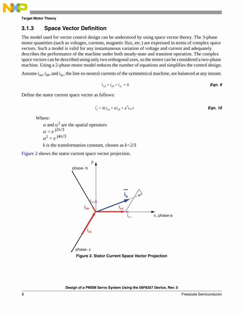
3.1.3 Space Vector Definition
The model used for vector control design can be understood by using space vector theory. The 3-phase motor quantities (such as voltages, currents, magnetic flux, etc.) are expressed in terms of complex space vectors. Such a model is valid for any instantaneous variation of voltage and current and adequately describes the performance of the machine under both steady-state and transient operation. The complex space vectors can be described using only two orthogonal axes, so the motor can be considered a two-phase machine. Using a 2-phase motor model reduces the number of equations and simplifies the control design.
Assume isa, isb, and isc, the line-to-neutral currents of the symmetrical machine, are balanced at any instant.
Eqn. 9
Define the stator current space vector as follows:
Eqn. 10
Where:α and α2 are the spatial operatorsα = e j2π/3
α2 = e j4π/3 k is the transformation constant, chosen as k=2/3
Figure 2 shows the stator current space vector projection.
Figure 2. Stator Current Space Vector Projection
isa isb isc 0=+ +
is k= isa aisb a2isc+ +( )
β
i s β
phase- b
Design of a PMSM Servo System Using the 56F8357 Device, Rev. 0
Freescale Semiconductor8

Target Motor Theory
The space vector defined by Equation 10 can be expressed utilizing the two-axis theory. The real part of the space vector is equal to the instantaneous value of the direct-axis stator current component, isα; its imaginary part is equal to the quadrature-axis stator current component, isβ. Thus, the stator current space vector in the stationary reference frame attached to the stator can be expressed as:
Eqn. 11
In symmetrical 3-phase machines, the direct and quadrature axis stator currents isα and isβ are rotational quadrature-phase (2-phase) current components, which are converted from the actual 3-phase stator currents as follows:
Eqn. 12
Eqn. 13
where:k=2/3 is a constant
The space vectors of other motor quantities (voltages, currents, magnetic fluxes etc.) can be defined in the same way as the stator current space vector.
For a description of the PMSM, the symmetrical 3-phase smooth-air-gap machine with sinusoidally distributed windings is considered. The voltage equations of stator in the instantaneous form can then be expressed as:
Eqn. 14
Eqn. 15
Eqn. 16
where:uSA, uSB and uSC are the instantaneous values of stator voltagesiSA, iSB and iSC are the instantaneous values of stator currentsψSA, ψSB, ψSC are instantaneous values of stator flux linkages, ψSA relates to phase SA, ψSB relates to SB, and ψSC relates to SC
is isα jisβ+=
isα k isa12---isb– 1
2---isc–⎝ ⎠
⎛ ⎞=
isβ k 32
------- isb isc–( )=
uSA RSiSA tdd ψSA+=
uSB RSiSB tdd ψSB+=
uSC RSiSC tdd ψSC+=
Design of a PMSM Servo System Using the 56F8357 Device, Rev. 0
Freescale Semiconductor 9

Target Motor Theory
Due to the large number of equations in the instantaneous form, (Equation 14, Equation 15, and Equation 16), it is more practical to rewrite the instantaneous equations using a two-axis theory (Clarke transformation). The PMSM can be expressed as:
Eqn. 17
Eqn. 18
Eqn. 19
Eqn. 20
Eqn. 21
where:
Equation 17 through Equation 21 represent the model of PMSM in the stationary frame α, β fixed to the stator.
α,β = the stator orthogonal coordinate systemuSα,β = the stator voltageiSα,β = the stator currentΨSα,β = the stator magnetic fluxΨM = the rotor magnetic fluxRS = the stator phase resistanceLS = the stator phase inductanceω / ωF = the electrical rotor speed / fields speedp = the number of poles per phaseJ = the inertiaTL = the load torqueΘr = the rotor position in a,b coordinate system
uSα RSiSα tdd ΨSα+=
uSβ RSiSβ tdd ΨSβ+=
ΨSα LSiSα ΨM Θr( )cos+=
ΨSβ LSiSβ ΨM Θr( )sin+=
tddω p
J--- 3
2---p ΨSαiSβ ΨSβiSα–( ) TL–=
Design of a PMSM Servo System Using the 56F8357 Device, Rev. 0
Freescale Semiconductor10
Target Motor Theory
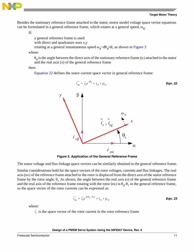
Besides the stationary reference frame attached to the stator, motor model voltage space vector equations can be formulated in a general reference frame, which rotates at a general speed, ωg.
If:a general reference frame is usedwith direct and quadrature axes x,y rotating at a general instantaneous speed ωg=dθg/dt, as shown in Figure 3
where:θg is the angle between the direct axis of the stationary reference frame (α) attached to the stator and the real axis (x) of the general reference frame
then:Equation 22 defines the stator current space vector in general reference frame:
Eqn. 22
Figure 3. Application of the General Reference Frame
The stator voltage and flux-linkage space vectors can be similarly obtained in the general reference frame.
Similar considerations hold for the space vectors of the rotor voltages, currents and flux linkages. The real axis (rα) of the reference frame attached to the rotor is displaced from the direct axis of the stator reference frame by the rotor angle, θr. As shown, the angle between the real axis (x) of the general reference frame and the real axis of the reference frame rotating with the rotor (rα) is θg-θr in the general reference frame, so the space vector of the rotor currents can be expressed as:
Eqn. 23
where: is the space vector of the rotor current in the rotor reference frame
isg isejθg–
isx jisy+==
β
x
y
g
irg irej θg θr–( )–
irx jiry+==
ir
Design of a PMSM Servo System Using the 56F8357 Device, Rev. 0
Freescale Semiconductor 11

Target Motor Theory
The space vectors of the rotor voltages and rotor flux linkages in the general reference frame can be similarly expressed.
The motor model voltage equations in the general reference frame can be expressed by transformations of the motor quantities from one reference frame to the general reference frame. The PMSM model is often used in vector control algorithms. The aim of vector control is to implement control schemes which produce high dynamic performance and are similar to those used to control DC machines. To achieve this, the reference frames may be aligned with the stator flux-linkage space vector, the rotor flux-linkage space vector, or the magnetizing space vector. The most popular reference frame is the reference frame attached to the rotor flux linkage space vector, with direct axis (d) and quadrature axis (q).
After transformation into d-q coordinates, the motor model as follows:
Eqn. 24
Eqn. 25
Eqn. 26
Eqn. 27
Eqn. 28
Below base speed, isd = 0, so Equation 28 can be reduced to the following form:
Eqn. 29
As Equation 29 shows, torque is dependent and can only be controlled directly by the current isq .
uSd RSiSd tdd ΨSd ωFΨSq–+=
uSq RSiSq tdd ΨSq ωFΨSd+ +=
ΨSd LSiSd ΨM+=
ΨSq LSiSq=
tddω p
J--- 3
2---p ΨSdiSq ΨSqiSd–( ) TL–=
tddω p
J--- 3
2---p ΨMiSq( ) TL–=
Design of a PMSM Servo System Using the 56F8357 Device, Rev. 0
Freescale Semiconductor12
Target Motor Theory
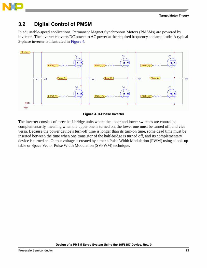
3.2 Digital Control of PMSMIn adjustable-speed applications, Permanent Magnet Synchronous Motors (PMSMs) are powered by inverters. The inverter converts DC power to AC power at the required frequency and amplitude. A typical 3-phase inverter is illustrated in Figure 4.
Figure 4. 3-Phase Inverter
The inverter consists of three half-bridge units where the upper and lower switches are controlled complementarily, meaning when the upper one is turned on, the lower one must be turned off, and vice versa. Because the power device’s turn-off time is longer than its turn-on time, some dead time must be inserted between the time when one transistor of the half-bridge is turned off, and its complementary device is turned on. Output voltage is created by either a Pulse Width Modulation (PWM) using a look-up table or Space Vector Pulse Width Modulation (SVPWM) technique.
Design of a PMSM Servo System Using the 56F8357 Device, Rev. 0
Freescale Semiconductor 13
Target Motor Theory
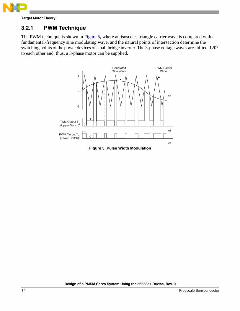
3.2.1 PWM Technique
The PWM technique is shown in Figure 5, where an isosceles triangle carrier wave is compared with a fundamental-frequency sine modulating wave, and the natural points of intersection determine the switching points of the power devices of a half bridge inverter. The 3-phase voltage waves are shifted 120° to each other and, thus, a 3-phase motor can be supplied.
Figure 5. Pulse Width Modulation
PWM CarrierWave
GeneratedSine Wave
PWM Output T1(Upper Switch)
01
0
1
PWM Output T2(Lower Switch)
1
0
-1
ωt
ωt
ωt
Design of a PMSM Servo System Using the 56F8357 Device, Rev. 0
Freescale Semiconductor14

Target Motor Theory
3.2.2 SVPWM Technique
The basic principle of the standard Space Vector Modulation Technique can be explained with the help of the power stage schematic diagram shown in Figure 6.
Figure 6. Power Stage Schematic Diagram
The top and bottom switches are working in a complementary mode; i.e., if the top switch, “SAt”, is ON, then the corresponding bottom switch, “SAb”, is OFF, and vice versa. Because value 1 is assigned to the ON state of the top switch and value 0 is assigned to the ON state of the bottom switch, the switching vector, [a, b, c]T, can be defined. Creating such a vector allows numerical definition of all possible switching states. Phase-to-phase voltages can then be expressed in terms of these states:
Eqn. 30
where:UDCBus is the instantaneous voltage measured on the DCBus
⎥⎥⎥
⎦
⎤
⎢⎢⎢
⎣
⎡
⎥⎥⎥
⎦
⎤
⎢⎢⎢
⎣
⎡
−−
−=
⎥⎥⎥
⎦
⎤
⎢⎢⎢
⎣
⎡
cba
UUUU
DCBus
CA
BC
AB
101110011
Design of a PMSM Servo System Using the 56F8357 Device, Rev. 0
Freescale Semiconductor 15

Target Motor Theory
Assuming that the motor is ideally symmetrical, it’s possible to write a matrix equation that expresses the motor phase voltages:
Eqn. 31
In a 3-Phase power stage configuration, shown in Figure 6, eight switching states (vectors), which are detailed in Figure 7, are possible. These states, together with the resulting instantaneous output line-to-line and phase voltages, are listed in Table 1.
The quantities of direct-α and quadrature-β components of the 2-phase orthogonal coordinate system, describing the 3-phase stator voltages, are expressed by the Clarke Transformation, arranged in a matrix form.
Eqn. 32
The 3-phase stator voltages, Ua, Ub, and Uc, are transformed via Clarke Transformation into quantities of direct-α and quadrature-β components of the 2-phase orthogonal coordinate system. The transformation results are listed in Table 2.
Table 1. Switching Patterns and Resulting Instantaneous Line-to-Line and Phase Voltages
a b c Ua Ub Uc UAB UBC UCA Vector
0 0 0 0 0 0 0 0 0 O000
1 0 0 2UDCBus/3 -UDCBus/3 -UDCBus/3 UDCBus 0 -UDCBus U0
1 1 0 UDCBus/3 UDCBus/3 -2UDCBus/3 0 UDCBus -UDCBus U60
0 1 0 -UDCBus/3 2UDCBus/3 -UDCBus/3 -UDCBus UDCBus 0 U120
0 1 1 -2UDCBus/3 UDCBus/3 UDCBus/3 -UDCBus 0 UDCBus U240
0 0 1 -UDCBus/3 -UDCBus/3 2UDCBus/3 0 -UDCBus UDCBus U300
1 0 1 UDCBus/3 -2UDCBus/3 UDCBus/3 UDCBus -UDCBus 0 U360
1 1 1 0 0 0 0 0 0 O111
Table 2. Switching Patterns, Space Vectors and α, β Voltage Components
a b c Uα Uβ Vector
0 0 0 0 0 O000
1 0 0 2UDCBus/3 0 U0
1 1 0 UDCBus/3 UDCBus/ U60
0 1 0 -UDCBus/3 UDCBus/ U120
0 1 1 -2UDCBus/3 0 U240
0 0 1 -UDCBus/3 UDCBus/ U300
1 0 1 UDCBus/3 UDCBus/ U360
1 1 1 0 0 O111
⎥⎥⎥
⎦
⎤
⎢⎢⎢
⎣
⎡
⎥⎥⎥
⎦
⎤
⎢⎢⎢
⎣
⎡
−−−−−−
=⎥⎥⎥
⎦
⎤
⎢⎢⎢
⎣
⎡
cba
U
UUU
DCBus
c
b
a
211121112
3
⎥⎥⎥
⎦
⎤
⎢⎢⎢
⎣
⎡
⎥⎥⎥⎥
⎦
⎤
⎢⎢⎢⎢
⎣
⎡
−
−−=⎥
⎦
⎤⎢⎣
⎡
c
b
a
UUU
UU
23
230
21
211
32
β
α
33
33
Design of a PMSM Servo System Using the 56F8357 Device, Rev. 0
Freescale Semiconductor16
Target Motor Theory
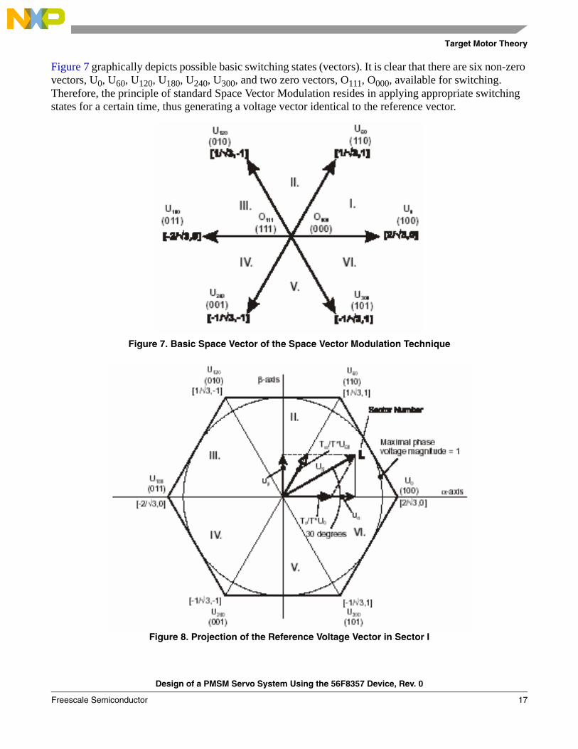
Figure 7 graphically depicts possible basic switching states (vectors). It is clear that there are six non-zero vectors, U0, U60, U120, U180, U240, U300, and two zero vectors, O111, O000, available for switching. Therefore, the principle of standard Space Vector Modulation resides in applying appropriate switching states for a certain time, thus generating a voltage vector identical to the reference vector.
Figure 7. Basic Space Vector of the Space Vector Modulation Technique
Figure 8. Projection of the Reference Voltage Vector in Sector I
Design of a PMSM Servo System Using the 56F8357 Device, Rev. 0
Freescale Semiconductor 17
Target Motor Theory
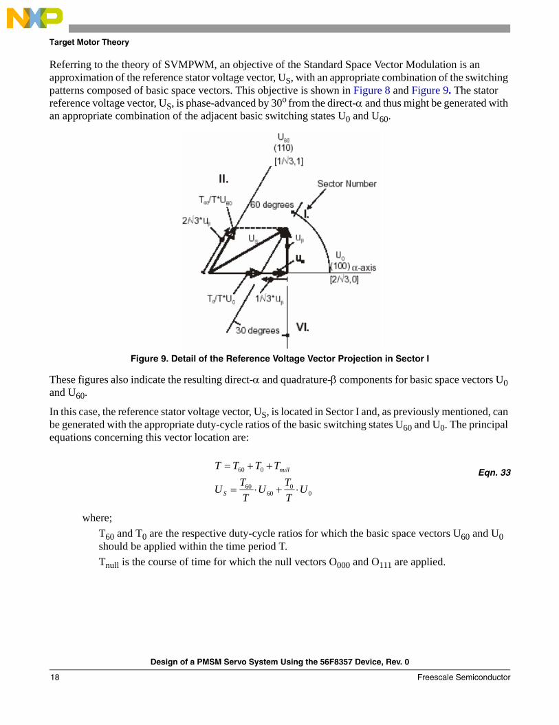
Referring to the theory of SVMPWM, an objective of the Standard Space Vector Modulation is an approximation of the reference stator voltage vector, US, with an appropriate combination of the switching patterns composed of basic space vectors. This objective is shown in Figure 8 and Figure 9. The stator reference voltage vector, US, is phase-advanced by 30o from the direct-α and thus might be generated with an appropriate combination of the adjacent basic switching states U0 and U60.
Figure 9. Detail of the Reference Voltage Vector Projection in Sector I
These figures also indicate the resulting direct-α and quadrature-β components for basic space vectors U0 and U60.
In this case, the reference stator voltage vector, US, is located in Sector I and, as previously mentioned, can be generated with the appropriate duty-cycle ratios of the basic switching states U60 and U0. The principal equations concerning this vector location are:
Eqn. 33
where;T60 and T0 are the respective duty-cycle ratios for which the basic space vectors U60 and U0 should be applied within the time period T. Tnull is the course of time for which the null vectors O000 and O111 are applied.
00
6060
060
UTTU
TTU
TTTT
S
null
⋅+⋅=
++=
Design of a PMSM Servo System Using the 56F8357 Device, Rev. 0
Freescale Semiconductor18

Target Motor Theory
Duty-cycle ratios can be calculated with Equation 34:
Eqn. 34
Considering that normalized magnitudes of basic space vectors are |U60| = |U0| = 2/ √3 and by substitution of the trigonometric expressions sin60o and tan60o by their quantities 2/ √3 and √3, respectively, Equation 33 and Equation 34 can be rearranged for the unknown duty-cycle ratios T60/T and T0/T:
Eqn. 35
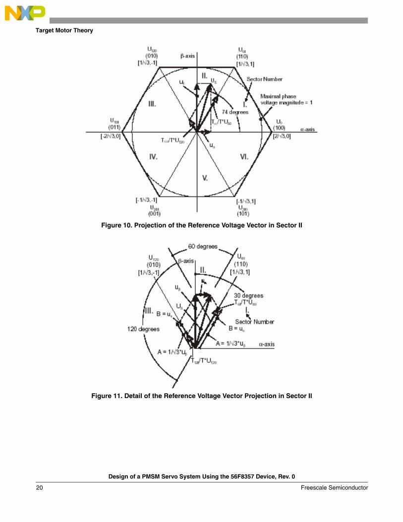
Sector II is depicted in Figure 10. In this particular case, the reference stator voltage vector, US, is generated by the appropriate duty-cycle ratios of the basic switching states, U60 and U120. The basic equations describing this sector are:
Eqn. 36
where:T120 and T60 are the respective duty-cycle ratios for which basic space vectors U120 and U60 should be applied within the time period T. Tnull is the course of time for which the null vectors O000 and O111 are applied. These resultant duty-cycle ratios are formed from the auxiliary components termed “A” and “B”.
The graphical representation of the auxiliary components is shown in Figure 11.
000
060
60
60tan
60sin
βα
β
uU
TTu
UT
Tu
+⋅=
⋅⋅=
)3(210
60
βα
β
uuTT
uT
T
−⋅⋅=
=
6060
120120
60120
UT
TUT
TU
TTTT
S
null
⋅+⋅=
++=
Design of a PMSM Servo System Using the 56F8357 Device, Rev. 0
Freescale Semiconductor 19
Target Motor Theory
Figure 10. Projection of the Reference Voltage Vector in Sector II
Figure 11. Detail of the Reference Voltage Vector Projection in Sector II
Design of a PMSM Servo System Using the 56F8357 Device, Rev. 0
Freescale Semiconductor20

Target Motor Theory
The equations describing those auxiliary time-duration components are:
Eqn. 37
Eqn. 38
Equation 37 and Equation 38 have been formed using the Sinus Rule. These equations can be rearranged for the calculation of the auxiliary time-duration components “A” and “B”. This is done simply by substituting the trigonometric terms sin30°, sin120°, and sin60⎦ by their numerical representations 1/2, √3/2 and 1/√3, respectively.
Eqn. 39
The resulting duty-cycle ratios, T120/T and T60/T, are then expressed in terms of the auxiliary time-duration components defined by Equation 40:
Eqn. 40
With the help of these equations and also considering normalized magnitudes of basic space vectors to be |U120| = |U60| = 2/ √3, the equations expressed for the unknown duty-cycle ratios of basic space vectors T120/T and T60/T can be written:
Eqn. 41
Eqn. 42
The duty-cycle ratios in remaining sectors can be derived using the same approach. The resulting equations will be similar to those derived for Sector I and Sector II.
βuA
=0
0
120sin30sin
αuB
=0
0
60sin60sin
α
β
uB
uA
=
⋅=3
1
BAUT
T
BAUT
T
+=⋅
−=⋅
6060
120120
)3(21120
αβ uuT
T⋅−⋅=
)3(2160
αβ uuT
T⋅+⋅=
Design of a PMSM Servo System Using the 56F8357 Device, Rev. 0
Freescale Semiconductor 21

Target Motor Theory
These definitions depict duty-cycle ratios of basic space vectors for all sectors:• Three auxiliary variables:
— X = uβ— Y= 1/2 (uβ + √3 uα )— Z= 1/2 (uβ - √3 uα )
• Two expressions:— t_1— t_2
which generally represent duty-cycle ratios of basic space vectors in the respective sector. For example, t_1 and t_2 represent duty-cycle ratios of basic space vectors U60 and U0 for the first sector; t_1 and t_2 represent duty-cycle ratios of basic space vectors U120 and U60 for the second sector and so on.
For each sector, the expressions t_1 and t_2 are listed in Table 3 in terms of auxiliary variables X, Y and Z.
For the determination of auxiliary variables X, Y and Z, the sector number is required. This information can be obtained by several methods. One approach requires the use of a modified Inverse Clark Transformation to transform the direct-α and quadrature-β components into a balanced 3-phase quantity, uref1, uref2 and uref3, used for straightforward calculation of the sector number, to be shown in Figure 13 and Figure 14.
Eqn. 43
Eqn. 44
Eqn. 45
The modified Inverse Clark Transformation projects the quadrature-uβ component into uref1, as shown in Figure 12 and Figure 13; voltages generated by the conventional Inverse Clark Transformation project the direct-uα component into uref1.
Table 3. Determination of the Expressions t_1 and t_2 for All Sectors
Sectors U0, U60 U60, U120 U120, U180 U180, U240 U240, U300 U300, U0
t_1 X Z -Y -X -Z Y
t_2 -Z Y X Z -Y -X
βuuref =1
23
2αβ uu
uref
⋅+−=
23
3αβ uu
uref
⋅−−=
Design of a PMSM Servo System Using the 56F8357 Device, Rev. 0
Freescale Semiconductor22
Target Motor Theory
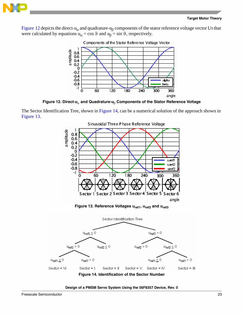
Figure 12 depicts the direct-uα and quadrature-uβ components of the stator reference voltage vector US that were calculated by equations uα = cos ϑ and uβ = sin ϑ, respectively.
Figure 12. Direct-uα and Quadrature-uβ Components of the Stator Reference Voltage
The Sector Identification Tree, shown in Figure 14, can be a numerical solution of the approach shown in Figure 13.
Figure 13. Reference Voltages uref1, uref2 and uref3
Figure 14. Identification of the Sector Number
Design of a PMSM Servo System Using the 56F8357 Device, Rev. 0
Freescale Semiconductor 23

Target Motor Theory
It should be pointed out that, in the worst case, three simple comparisons are required to precisely identify the sector of the stator reference voltage vector. For example, if the stator reference voltage vector resides according to the one shown in Figure 8, the stator reference voltage vector is phase-advanced by 30° from the direct axis, which results in positive quantities of uref1 and uref2 and a negative quantity of uref3; refer to Figure 13. If these quantities are used as inputs to the Sector Identification Tree, the product of those comparisons will be Sector I. Using the same approach identifies Sector II, if the stator reference voltage vector is located as shown in Figure 10. The variables t1, t2 and t3, representing switching duty-cycle ratios of the respective 3-phase system, are found by the following equations:
Eqn. 46
Eqn. 47
Eqn. 48
where:T is the switching periodt_1 and t_2 are duty-cycle ratios of basic space vectors, given for the respective sector
Table 3 and Equation 46, Equation 47, and Equation 48 are specific solely to the standard Space Vector Modulation technique; consequently, other Space Vector Modulation techniques will require deriving different equations. The next step is to assign the correct duty-cycle ratios, t1, t2, and t3, to the respective motor phases. This is a simple task, accomplished in view of the position of the stator reference voltage vector; see Table2-4.
The most popular power devices for motor control applications are Power MOSFETs and IGBTs. A Power MOSFET is a voltage-controlled transistor. It is designed for high-frequency operation and has a low voltage drop, so it has low power losses. However, the saturation temperature sensitivity limits the MOSFET application in high-power applications.
An insulated-gate bipolar transistor (IGBT) is a bipolar transistor controlled by a MOSFET on its base. The IGBT requires low drive current, has fast switching time, and is suitable for high switching frequencies. The disadvantage is the higher voltage drop of a bipolar transistor, causing higher conduction losses.
Table 4. Assignment of the Duty-Cycle Ratios to the Corresponding Motor Phase
Sectors U0, U60 U60, U120 U120, U180 U180, U240 U240, U300 U300, U0
pwm_a t3 t2 t1 t1 t2 t3
pwm_b t2 t3 t3 t2 t1 t1
pwm_c t1 t1 t2 t3 t3 t2
22_1_
1ttTt −−
=
1_12 ttt +=
2_23 ttt +=
Design of a PMSM Servo System Using the 56F8357 Device, Rev. 0
Freescale Semiconductor24
Target Motor Theory
3.2.3 Vector Control of PMSM
Vector control is an elegant method to control a Permanent Magnet Synchronous Motor (PMSM), in which a field-oriented theory controls space vectors of magnetic flux, current, and voltage. It is possible to set up the coordinate system to decompose the vectors into a magnetic field-generating function and a torque-generating function. The structure of the motor controller (vector control controller) is then almost the same as for a separately-excited DC motor, which simplifies the control of PMSM. This vector control technique was developed specifically to achieve a similarly dynamic performance in PMSMs.
In this method, the stator current’s field-generating and torque-generating functions must be broken down to able to separately control the magnetic flux and the torque. In order to do so, the rotary coordinate system must be connected to the rotor magnetic field; this system is generally called a “d-q coordinate system”. The transformation from rotary to stationary coordinate systems demands very high CPU performance. The Freescale 56F8357 device is well suited for use in a vector control algorithm.
3.2.4 Block Diagram of Vector Control
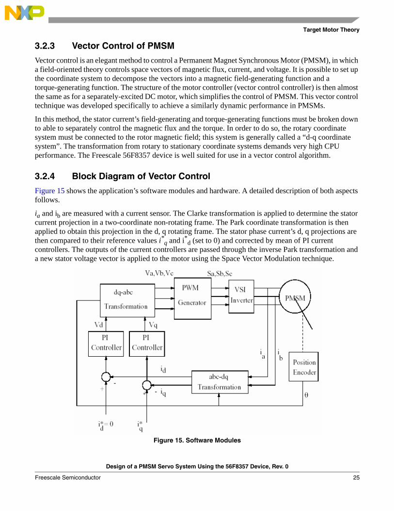
Figure 15 shows the application’s software modules and hardware. A detailed description of both aspects follows.
ia and ib are measured with a current sensor. The Clarke transformation is applied to determine the stator current projection in a two-coordinate non-rotating frame. The Park coordinate transformation is then applied to obtain this projection in the d, q rotating frame. The stator phase current’s d, q projections are then compared to their reference values i*q and i*d (set to 0) and corrected by mean of PI current controllers. The outputs of the current controllers are passed through the inverse Park transformation and a new stator voltage vector is applied to the motor using the Space Vector Modulation technique.
Figure 15. Software Modules
Design of a PMSM Servo System Using the 56F8357 Device, Rev. 0
Freescale Semiconductor 25
Target Motor Theory
3.2.5 Servo Control of PM Synchronous Motor
Figure 16. PMSM Servo Control Scheme
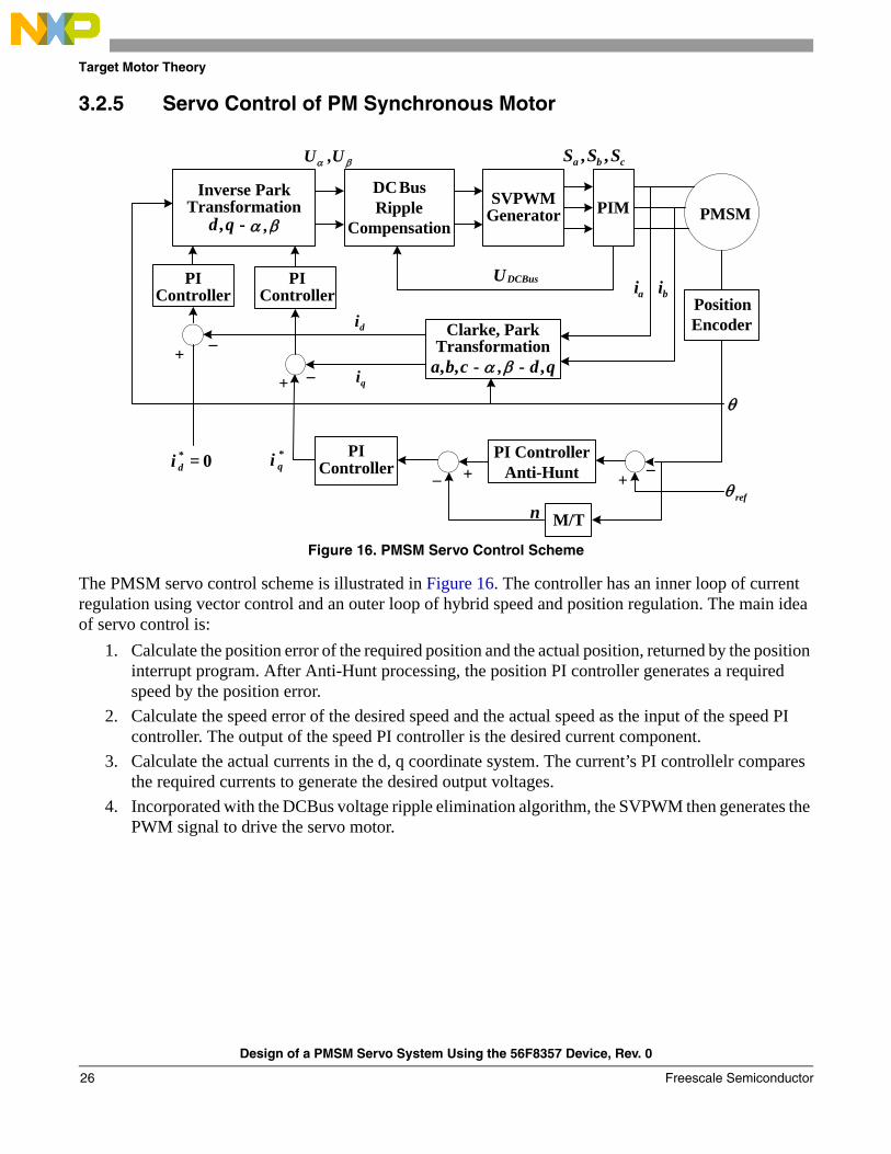
The PMSM servo control scheme is illustrated in Figure 16. The controller has an inner loop of current regulation using vector control and an outer loop of hybrid speed and position regulation. The main idea of servo control is:
1. Calculate the position error of the required position and the actual position, returned by the position interrupt program. After Anti-Hunt processing, the position PI controller generates a required speed by the position error.
2. Calculate the speed error of the desired speed and the actual speed as the input of the speed PI controller. The output of the speed PI controller is the desired current component.
3. Calculate the actual currents in the d, q coordinate system. The current’s PI controllelr compares the required currents to generate the desired output voltages.
4. Incorporated with the DCBus voltage ripple elimination algorithm, the SVPWM then generates the PWM signal to drive the servo motor.
+_
+_
M/T
SVPWMGenerator
0=
DCBusRipple
Compensation
+_+_
PIM PMSM
Clarke, ParkTransformation
qdcba ,,, --
Inverse ParkTransformation
, -qd
cba SSS ,,
n
DCBusUai bi
PIController
PIController Position
Encoder
PI ControllerAnti-Hunt
*qi PI
Controller*di
di
qi
βα ,
βα ,
θ
refθ
βα U,U
Design of a PMSM Servo System Using the 56F8357 Device, Rev. 0
Freescale Semiconductor26

Servo Control System
4 Servo Control System
4.1 System ConceptThe motor servo control system is designed to drive a 3-phase Permanent Magnet Synchronous Motor (PMSM) in a servo system. The application meets the following performance specifications:
• Vector control of a PMSM using the quadrature encoder as a position and speed sensor• Targeted for the 56F8357EVM• Runs on a 3-phase PMSM control development platform at 36V DC• The control technique incorporates:
— Vector Control with position closed-loop and speed closed-loop— Rotation in both directions— Starts from any motor position with rotor alignment— Minimum speed of 5rpm— Maximum speed of 600rpm at input power line 36V DC
• Manual interface includes:— Start/Stop switch— Position/speed switch,— Set value/actual value display switch— Up/Down push button control— LED indicator— Power supply— Alarm— Position/speed— Run/stop
• PC master software control interface includes:— Motor start/stop— Speed set up
• PC master software remote monitor• Overvoltage, undervoltage, overcurrent fault protection
Design of a PMSM Servo System Using the 56F8357 Device, Rev. 0
Freescale Semiconductor 27

Servo Control System
The PM synchronous drive introduced here is designed to power a PMSM with a quadrature encoder. Its specifications are detailed in Table 5.
4.2 Servo Control Drive ConceptA standard system concept is used with this drive. The system incorporates the following hardware:
• 3-phase PMSM development platform• Feedback sensors for:
— Position (Quadrature Encoder)— DCBus voltage— Phase currents
• 56F8357EVM
The drive can be controlled in two different operating modes: • In the Manual operating mode, the required position or speed is set by the Start/Stop switch and
the Up/Down push buttons. Position/Speed control is selected by the Position/Speed switch. • In the PC master software operating mode, the required position or speed and Start/Stop switch
are set by the PC.
Table 5. System Specifications
Motor Characteristics Motor Type 4 poles, 3-phase, star-connected, PMSM
Speed Range 8600rpm (195V rated line voltage)
Maximum Electrical Power 201W
Phase Voltage 3*195V
Phase Current 1A
Drive Characteristics Speed Range < 1000rpm
Input Voltage 36V DC
Maximum DCBus Voltage 36V DC
Control Algorithm Position/Speed Closed-Loop Control
Optoisolation Required
Design of a PMSM Servo System Using the 56F8357 Device, Rev. 0
Freescale Semiconductor28
Servo Control System
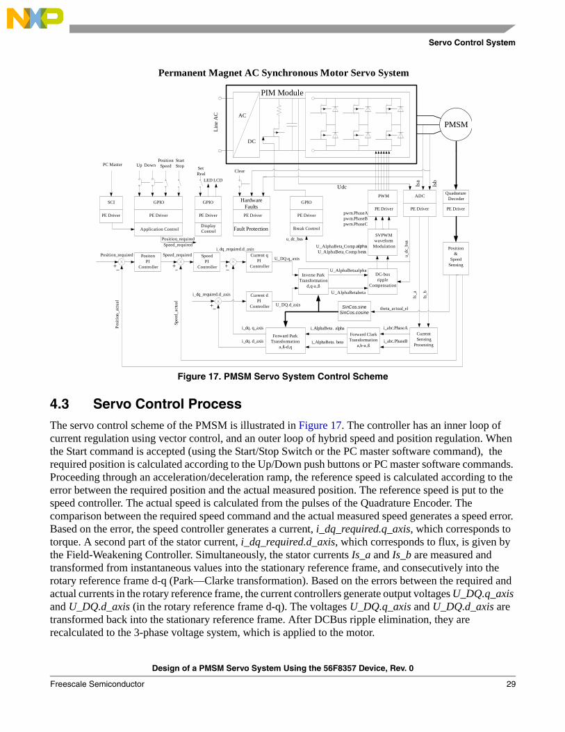
Figure 17. PMSM Servo System Control Scheme
4.3 Servo Control ProcessThe servo control scheme of the PMSM is illustrated in Figure 17. The controller has an inner loop of current regulation using vector control, and an outer loop of hybrid speed and position regulation. When the Start command is accepted (using the Start/Stop Switch or the PC master software command), the required position is calculated according to the Up/Down push buttons or PC master software commands. Proceeding through an acceleration/deceleration ramp, the reference speed is calculated according to the error between the required position and the actual measured position. The reference speed is put to the speed controller. The actual speed is calculated from the pulses of the Quadrature Encoder. The comparison between the required speed command and the actual measured speed generates a speed error. Based on the error, the speed controller generates a current, i_dq_required.q_axis, which corresponds to torque. A second part of the stator current, i_dq_required.d_axis, which corresponds to flux, is given by the Field-Weakening Controller. Simultaneously, the stator currents Is_a and Is_b are measured and transformed from instantaneous values into the stationary reference frame, and consecutively into the rotary reference frame d-q (Park—Clarke transformation). Based on the errors between the required and actual currents in the rotary reference frame, the current controllers generate output voltages U_DQ.q_axis and U_DQ.d_axis (in the rotary reference frame d-q). The voltages U_DQ.q_axis and U_DQ.d_axis are transformed back into the stationary reference frame. After DCBus ripple elimination, they are recalculated to the 3-phase voltage system, which is applied to the motor.
Permanent Magnet AC Synchronous Motor Servo System
Position_required
Posi
tion_
actu
al
PositonPI
Controller
Speed_required
Spee
d_ac
tual
SpeedPI
Controller
i_dq_required.d_axis
i_dq. q_axis
Current qPI
Controller
i_dq_required.d_axis Current dPI
Controller
i_dq. d_axis
U_DQ.q_axis
U_DQ.d_axis
Inverse Park Transformation
d,q-a,ß
U_AlphaBeta.alpha
U_AlphaBeta.beta
DC-busripple
Compensation
SVPWMwaveform
Modulation
PWM
PE Driver
Forward ParkTransformation
a,ß-d,q
Forward ClarkTransformation
a,b-a,ß
i_AlphaBeta. alpha
i_AlphaBeta. beta
CurrentSensing
Prosessing
i_abc.PhaseA
i_abc.PhaseB
ADC
PE Driver
QuadratureDecoder
PE Driver
Position&
SpeedSensing
u_dc
_bus
Is_a
Is_b
SinCos.sine SinCos.cosine
theta_actual_el
GPIO
PE Driver
Break Control
Hardware FaultsPE Driver
Fault Protection
GPIO
PE Driver
Application Control
SCI
PE Driver
Up DownPositionSpeedPC Master
AC
DC
Udc Isa
Isb
U_AlphaBeta_Comp.alphaU_AlphaBeta_Comp.beta
pwm.PhaseApwm.PhaseBpwm.PhaseC
PIM Module
GPIO
PE Driver
DisplayControl
LED LCD
Speed_required
PMSM
Line
AC
Clear
u_dc_bus
SetReal
StartStop
Position_required
Design of a PMSM Servo System Using the 56F8357 Device, Rev. 0
Freescale Semiconductor 29
System Hardware Design
Besides the main control loop, the DCBus voltage and the motor phase current are measured during the control process. They are used to protect the drive from overvoltage, undervoltage and overcurrent.
If any of these faults occur, the motor control PWM outputs are disabled in order to protect the drive, and the fault state of the system is displayed by the on-board LED.
This dual-loop structure ensures a fast torque response by using vector control, high position accuracy with the position controller, and fast tracking performance with hybrid (speed and position) control. The structure is also important to secure the stability of the system.
5 System Hardware Design
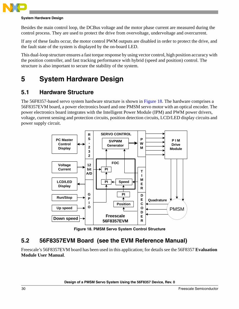
5.1 Hardware StructureThe 56F8357-based servo system hardware structure is shown in Figure 18. The hardware comprises a 56F8357EVM board, a power electronics board and one PMSM servo motor with an optical encoder. The power electronics board integrates with the Intelligent Power Module (IPM) and PWM power drivers, voltage, current sensing and protection circuits, position detection circuits, LCD/LED display circuits and power supply circuit.
Figure 18. PMSM Servo System Control Structure
5.2 56F8357EVM Board (see the EVM Reference Manual)Freescale’s 56F8357EVM board has been used in this application; for details see the 56F8357 Evaluation Module User Manual.
P I MDrive
Module
Quadrature
PMSM
TI
MER
GPIO
Run/Stop
Up speed
Down speed
RS-232
LCD/LEDDisplay
PC MasterControlDisplay
PWM
12bitA/D
VoltageCurrent
Position
Speed
Freescale56F8357EVM
PI
PI
SVPWMGenerator
PI
FOC
SERVO CONTROL
DECODER
Design of a PMSM Servo System Using the 56F8357 Device, Rev. 0
Freescale Semiconductor30
System Hardware Design
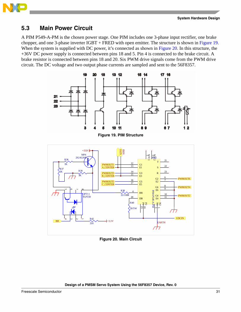
5.3 Main Power CircuitA PIM P549-A-PM is the chosen power stage. One PIM includes one 3-phase input rectifier, one brake chopper, and one 3-phase inverter IGBT + FRED with open emitter. The structure is shown in Figure 19. When the system is supplied with DC power, it’s connected as shown in Figure 20. In this structure, the +36V DC power supply is connected between pins 18 and 5. Pin 4 is connected to the brake circuit. A brake resistor is connected between pins 18 and 20. Six PWM drive signals come from the PWM drive circuit. The DC voltage and two output phase currents are sampled and sent to the 56F8357.
Figure 19. PIM Structure
Figure 20. Main Circuit
R40
50/5W
+3.3V
R372K
R36
1K
NPN2S2412KR
R39
3K
+15(V)
R38
33/100R
23
8765
14
OPT11TLP559
R42
330
NTC
11 N
TC2
2
G112
E113
G314
E315
G516
E517
T 21
S 22
R 23
G2 6
E2 7
G6 8
E6 9
N1
3
BR4
N2
5
P119
P218
G4 10
E4 11DB20
JP22
PIM-P549-A
-PM
Main Circuit
PWMOUT1A_CENTER
PWMOUT2
PWMOUT3B_CENTER
PWMOUT4
PWMOUT5C_CENTER
PWMOUT6
UDCINBR
IBIN
IAIN
EARTH
Design of a PMSM Servo System Using the 56F8357 Device, Rev. 0
Freescale Semiconductor 31
System Hardware Design
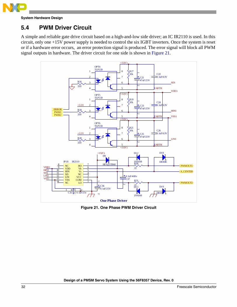
5.4 PWM Driver CircuitA simple and reliable gate drive circuit based on a high-and-low side driver; an IC IR2110 is used. In this circuit, only one +15V power supply is needed to control the six IGBT inverters. Once the system is reset or if a hardware error occurs, an error protection signal is produced. The error signal will block all PWM signal outputs in hardware. The driver circuit for one side is shown in Figure 21.
Figure 21. One Phase PWM Driver Circuit
2
3
8
7
6
5
1
4
OPT5TLP559
2
3
8
7
6
5
1
4
OPT6TLP559
+3.3V
R18
330
+3.3V
R20
330
12
C2347uF/25V
R1910k C24
0.1uF/63V
12
C2547uF/25V
R2110k C26
0.1uF/63V
LO 1COM 2VCC 3NC 4Vs 5Vb 6HO 7NC8
VDD9
HIN10
SD11
LIN12
VSS13
NC14
JP18 IR2110
12
C360.1uF/25V
12
C370.1uF/400v
+15(V)
+15(V)
+15(V)EARTH
EARTH
+15(V)
2
3
8
7
6
5
1
4
OPT4TLP559
R16
330
12
C2147uF/25V
R1710k C22
0.1uF/63V
+15(V)
EARTH
R30
22
R31
22
1 2C35 0.1uF/25v
D18
DIODE
D19
DIODE
D13
1N4148
D12
1N4148
D9
HFA25TB60
VDD1
HIN1
SD1
LIN1
VSS1
VDD1HIN1SD1LIN1VSS1
ERROR
PWM2PWM1
PWMOUT1
A_CENTER
PWMOUT2
One Phase Driver
Design of a PMSM Servo System Using the 56F8357 Device, Rev. 0
Freescale Semiconductor32

System Hardware Design
5.5 DC Voltage and Phase Current Sample CircuitA DC voltage sample circuit is shown in Figure 22. DC voltage is sensed by a voltage transducer, LEM (LV28-P) supplied with +15V. Through a voltage follower circuit and a simple voltage divider circuit, the voltage signal is sent to the 56F8357’s A/D port. In this system, the LEM’s power resistor is 3.6K, the LEM’s primary side current is 10mA, the secondary output current is 25mA, and the sampling resistor is 100Ω, creating a maximum input voltage of 36V, which is converted into a 2.5V output voltage to the A/D port.
Figure 22. DCBus Voltage Detection Circuit
The output phase current sample circuit is shown in Figure 23. The phase current is sensed by a current voltage transducer, LEM (LA28-NP). The LEM scale is 5A, the primary maximum input current is 1.65/5 * 10 = 3.3mA, the secondary output current is 1.65/5 * 25 = 8.25mA, and the sampling resistor is 300Ω, creating a maximum voltage of 2.475V. Through a follower circuit and a simple divider circuit, the maximum voltage to the A/D port is 2.475/2 + 2.5/2 = 2.4875V and the minimum voltage is -2.475/2 + 2.5/2 = 0.0125V.
Figure 23. Phase Current Detection Circuit
The voltage signal obtained is sent to the 56F8357’s A/D port.
The sensed voltage and current signals are also used as hardware and software protection signals, such as undervoltage, overvoltage and overcurrent.
R5310K
R55
4.7K
R47200.1%.0.5W
R51
2.2K
R49
10k
R502.2K
C500.024uF
C490.1uF
3
21
84
U4A
LM3585
67
U4B
LM358
2
3
74
6
18
U1
OP07
+15V
+15V-15V
-15VR5210k
R54 10K
R455K
R4630k/8w -15V
+15V1 3
42 5
JP24
LEM-U
GROUND
C51 10nF
UDC_INPUTD24DIODE
D25DIODE
Voltage Detect
UDCIN
UDCOUTUDC A/D
2.5V
+2.5V
R56200.1%.0.5W
2
3
74
6
18
U2
OP07
-15V
+15V
R61
2.2KR5810K
R592.2K
C530.024uF
C520.1uF
3
21
84
U5A
LM358
+15V
-15VR6010k
5
67
U5B
LM358
R6310K
R645K
R6210K
R65
5K1234 1157 1289 13106
JP25 LEM-IA-5A
-15V
+15V
+2.5V
C54
10nF
IA_INPUT
D26DIODE
D27DIODE
IA OverCurrent Detect
Phase Current Detect
IAIN
IAOUT
IA
IA A/D
Design of a PMSM Servo System Using the 56F8357 Device, Rev. 0
Freescale Semiconductor 33
System Hardware Design
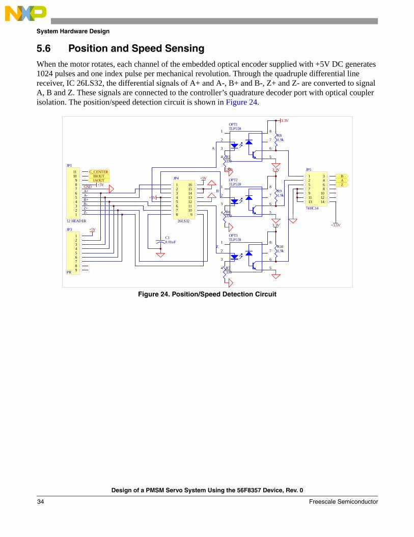
5.6 Position and Speed SensingWhen the motor rotates, each channel of the embedded optical encoder supplied with +5V DC generates 1024 pulses and one index pulse per mechanical revolution. Through the quadruple differential line receiver, IC 26LS32, the differential signals of A+ and A-, B+ and B-, Z+ and Z- are converted to signal A, B and Z. These signals are connected to the controller’s quadrature decoder port with optical coupler isolation. The position/speed detection circuit is shown in Figure 24.
Figure 24. Position/Speed Detection Circuit
2
3
8
7
6
5
1
4
OPT2TLP559
3.3V
2
3
8
7
6
5
1
4
OPT3TLP559
3.3V
2
3
8
7
6
5
1
4
OPT1TLP559
3.3V
R5330
R6330
R7330
R81.9k
R91.9k
R101.9k
1 162 153 144 135 126 117 108 9
JP4
26LS32
+5V
+5V
C10.01uF
123456789
JP3
PR
+5V
+5V
1 32 45 67 89 1011 1213 14
JP5
74HC14
+3.3V
GND
GND
A+A-B+B-Z+Z-
B
Z
A
Position/Speed Detect
123456789
1011
JP1
12 HEADER
C_CENTERIBOUTIAOUT
BAZ
Design of a PMSM Servo System Using the 56F8357 Device, Rev. 0
Freescale Semiconductor34

System Hardware Design
5.7 Overcurrent Protection CircuitTo protect the system, an overcurrent signal is produced when an overcurrent fault is detected and the related LED is lighted. An ERROR signal created with the signals of BR and RESET is used to block the PWM signals. The circuit is shown in Figure 25. In this circuit, TL431 provides a comparison of benchmark voltage. A dual d-type positive-edge-triggered flip-flop IC 74LS74 locks the error signal. This signal will be cleared when the “clear” button is pressed.
Figure 25. Overcurrent Protection Circuit
2
37
6 51
84
U7
LM311
2
37
6 51
84
U8
LM311
11
22
D35LED
R8310K
R8410K
R7810K
R79 10K
R803K
R8810k
C591uF
C581uF
+
C6010uF/25V
R8510K
R8633K
+3.3V
+3.3 V
-15V
+3.3VR871K
+3.3V
+15(V)
+15V
-4.3ERROR
+4.3VERROR
-15V
·¢¹â±¨¾¯µÆ
R76
100
R94 10K
C63 0.1uF
R95
5K
R93
2K
4.3V
+15V
CHK-+REF
2 3
1
D37TL431
S2clear
R77100
R91 10K
C61 0.1uF
R92
5K
R89
2K
-4.3VCHK--REF
2 3
1
D36TL431
+
C64 10uF/10V
R90
10K
+C62 10uF/10V
1D2
1Q 5
1Q 6
1CLK3 1PRE4
1CLR1
2D12
2Q 9
2Q 8
2CLK11 2PRE10
2CLR13
JP29
74LS74X2
CLR
D30IN4148
D31IN4148
D32IN4148
D33IN4148
D34IN4148
CHK+
CHK-
R81 100
R82 100
Over Current Protect
IAIA
IERROR
1
23
U1A
74LS08
ERROR
4
56
U1B
74LS08
9
108
U1C
74LS08
IERROR
BR
RESET
15V
Design of a PMSM Servo System Using the 56F8357 Device, Rev. 0
Freescale Semiconductor 35
System Hardware Design
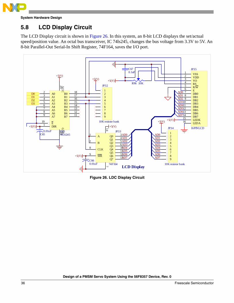
5.8 LCD Display CircuitThe LCD Display circuit is shown in Figure 26. In this system, an 8-bit LCD displays the set/actual speed/position value. An octal bus transceiver, IC 74ls245, changes the bus voltage from 3.3V to 5V. An 8-bit Parallel-Out Serial-In Shift Register, 74F164, saves the I/O port.
Figure 26. LDC Display Circuit
VSS1
VDD2
VO3
RS4
R/W5
E6
DB07
DB18
DB29
DB310
DB411
DB512
DB613
DB714
LEDK15
LEDA16
JP35
16PINLCD
A02
A13
A24
A35
A46
A57
A68
A79
B0 18
B1 17
B2 16
B3 15
B4 14
B5 13
B6 12
B7 11
E19
DIR1
VC
C20
GN
D10JP3174LS245 1
23456789
JP34
10K resistor bank
123456789
JP32
10K resistor bank
+5(V)
+5(V)
+5(V)
A1
B2
Q0 3
Q1 4
Q2 5
Q3 6
CLK8
MR9
Q4 10
Q5 11
Q6 12
Q7 13
714
JP33
74F164
+5(V)
+5(V)
+5(V) +5(V)
R96 10K
C670.1uF
+5(V)
C650.01uF
C660.01uF
AD0AD1AD2AD3AD4AD5AD6AD7 AD7
AD6AD5AD4AD3AD2AD1AD0
AD7AD6AD5AD4AD3AD2AD1AD0
LCD Display
D0
D2D1
D3
Design of a PMSM Servo System Using the 56F8357 Device, Rev. 0
Freescale Semiconductor36
System Hardware Design
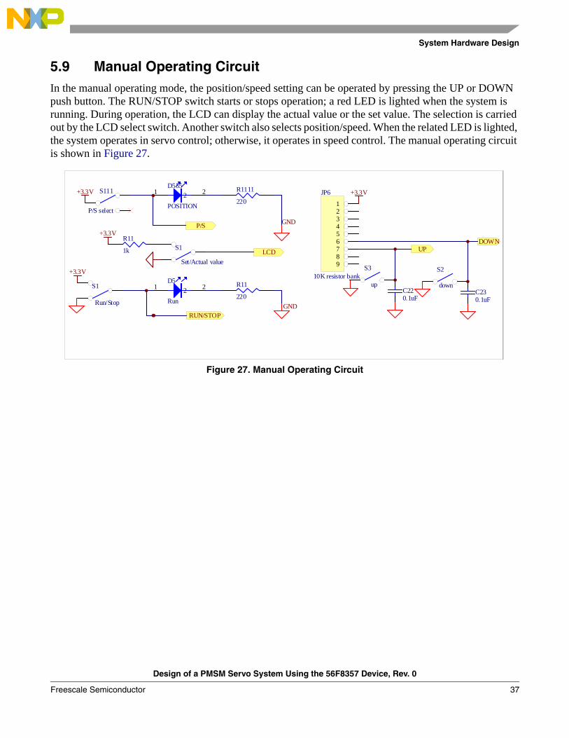
5.9 Manual Operating CircuitIn the manual operating mode, the position/speed setting can be operated by pressing the UP or DOWN push button. The RUN/STOP switch starts or stops operation; a red LED is lighted when the system is running. During operation, the LCD can display the actual value or the set value. The selection is carried out by the LCD select switch. Another switch also selects position/speed. When the related LED is lighted, the system operates in servo control; otherwise, it operates in speed control. The manual operating circuit is shown in Figure 27.
Figure 27. Manual Operating Circuit
Run/Stop Up Down P/S LCD
123456789
JP6
10K resistor bank
+3.3V
11 2 2D5
Run
R11
220S1
Run/Stop
+3.3V
GND
11 2 2D555
POSITION
R1111
220S111
P/S select
+3.3V
GND
S1
Set/Actual value
+3.3VP/S
RUN/STOP
LCD UPDOWNR11
1k
S3
up
S2
downC220.1uF
C230.1uF
Design of a PMSM Servo System Using the 56F8357 Device, Rev. 0
Freescale Semiconductor 37
System Software Organization
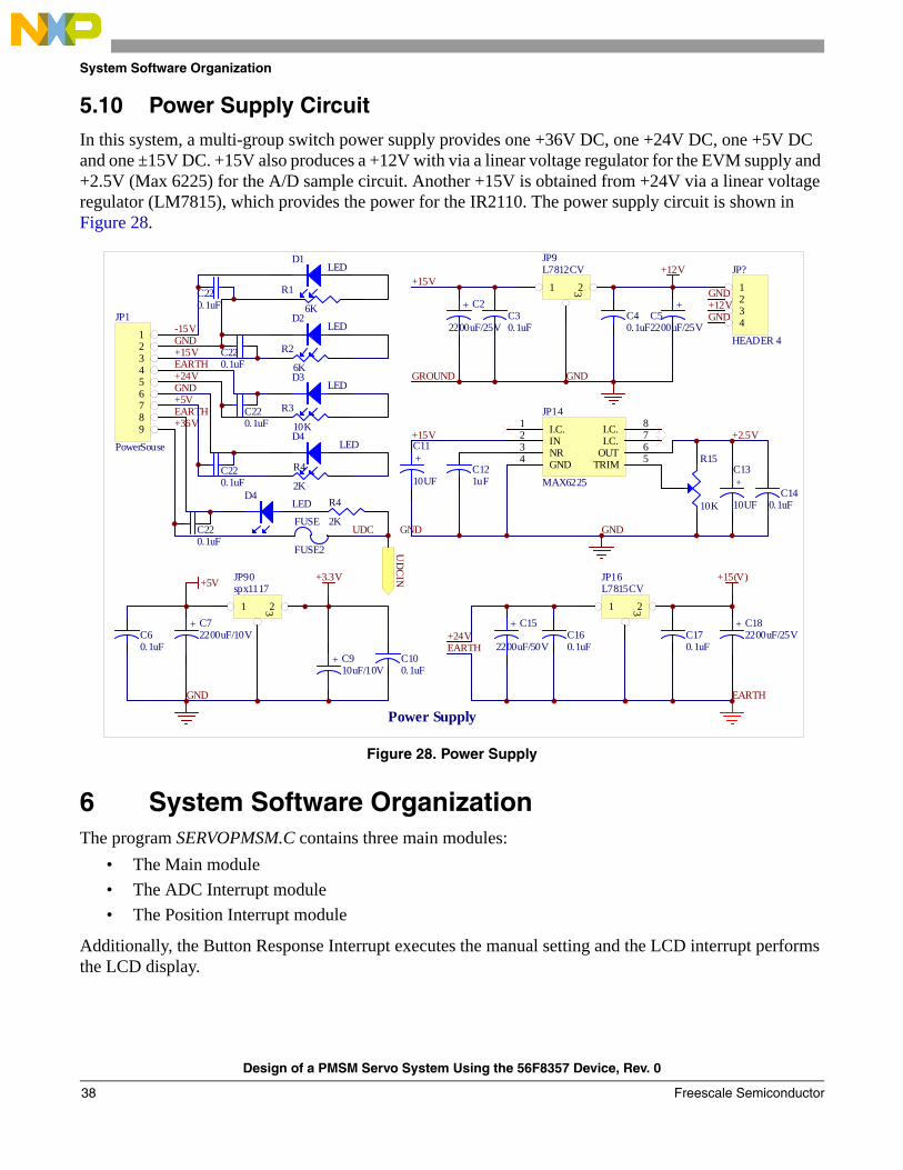
5.10 Power Supply CircuitIn this system, a multi-group switch power supply provides one +36V DC, one +24V DC, one +5V DC and one ±15V DC. +15V also produces a +12V with via a linear voltage regulator for the EVM supply and +2.5V (Max 6225) for the A/D sample circuit. Another +15V is obtained from +24V via a linear voltage regulator (LM7815), which provides the power for the IR2110. The power supply circuit is shown in Figure 28.
Figure 28. Power Supply
6 System Software OrganizationThe program SERVOPMSM.C contains three main modules:
• The Main module• The ADC Interrupt module • The Position Interrupt module
Additionally, the Button Response Interrupt executes the manual setting and the LCD interrupt performs the LCD display.
Power Supply
FUSE
FUSE2
D2LED
D3LED
D4LED
-15VGND+15V
+24VEARTH
+5VGND
R1
6K
R3
10K
R4
2K
R2
6K
D1LED
123456789
JP1
PowerSouse
D4LED R4
2K
EARTH+36V
UDC
C220.1uF
C220.1uF
C220.1uF
C220.1uF
C220.1uF
+12V
1 23
JP9L7812CV
C30.1uF
C40.1uF
+C52200uF/25V
+15V
GND
+ C2
2200uF/25V
GND
GROUND
GND+12V
1234
JP?
HEADER 4
C60.1uF
+ C72200uF/10V
+5V
+ C910uF/10V
+3.3V
C100.1uF
1 23
JP90spx1117
GND
I.C.1
IN2
NR3
GND4
I.C. 8
I.C. 7
OUT 6
TRIM 5
JP14
MAX6225
+C11
10UF +C13
10UF
R15
10KC14
0.1uF
+15V
C121uF
GNDGND
+2.5V
+15(V)
1 23
JP16L7815CV
C160.1uF
C170.1uF
+ C182200uF/25V+24V
EARTH
+ C15
2200uF/50V
EARTH
UD
CIN
Design of a PMSM Servo System Using the 56F8357 Device, Rev. 0
Freescale Semiconductor38
System Software Organization
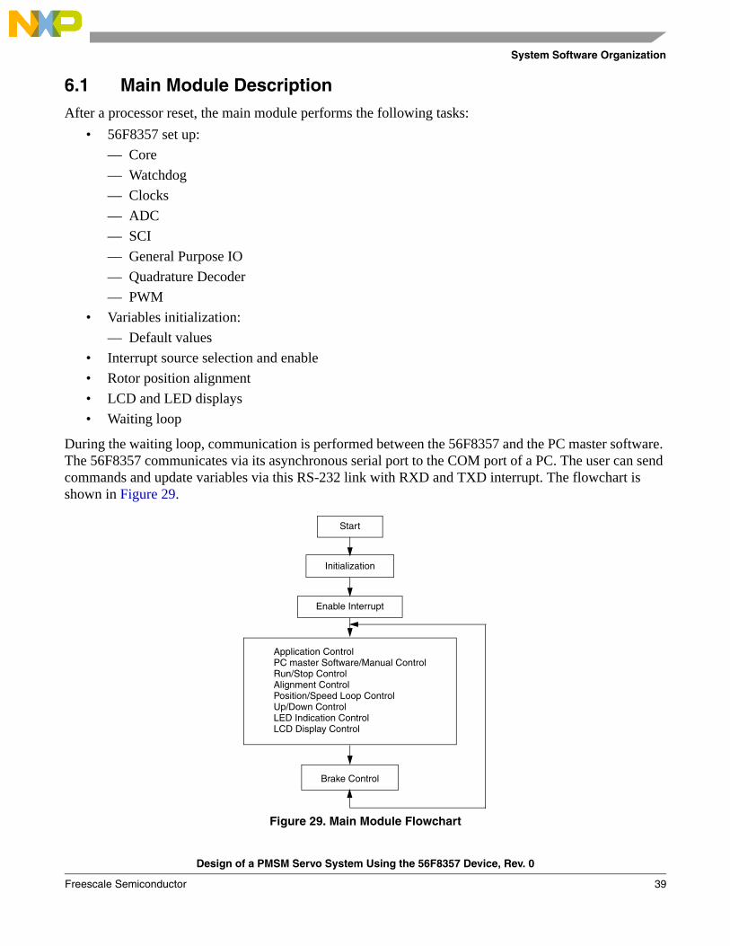
6.1 Main Module DescriptionAfter a processor reset, the main module performs the following tasks:
• 56F8357 set up:— Core— Watchdog— Clocks— ADC— SCI— General Purpose IO— Quadrature Decoder— PWM
• Variables initialization: — Default values
• Interrupt source selection and enable• Rotor position alignment• LCD and LED displays• Waiting loop
During the waiting loop, communication is performed between the 56F8357 and the PC master software. The 56F8357 communicates via its asynchronous serial port to the COM port of a PC. The user can send commands and update variables via this RS-232 link with RXD and TXD interrupt. The flowchart is shown in Figure 29.
Figure 29. Main Module Flowchart
Start
Initialization
Enable Interrupt
Application ControlPC master Software/Manual ControlRun/Stop ControlAlignment ControlPosition/Speed Loop ControlUp/Down ControlLED Indication ControlLCD Display Control
Brake Control
Design of a PMSM Servo System Using the 56F8357 Device, Rev. 0
Freescale Semiconductor 39
System Software Organization
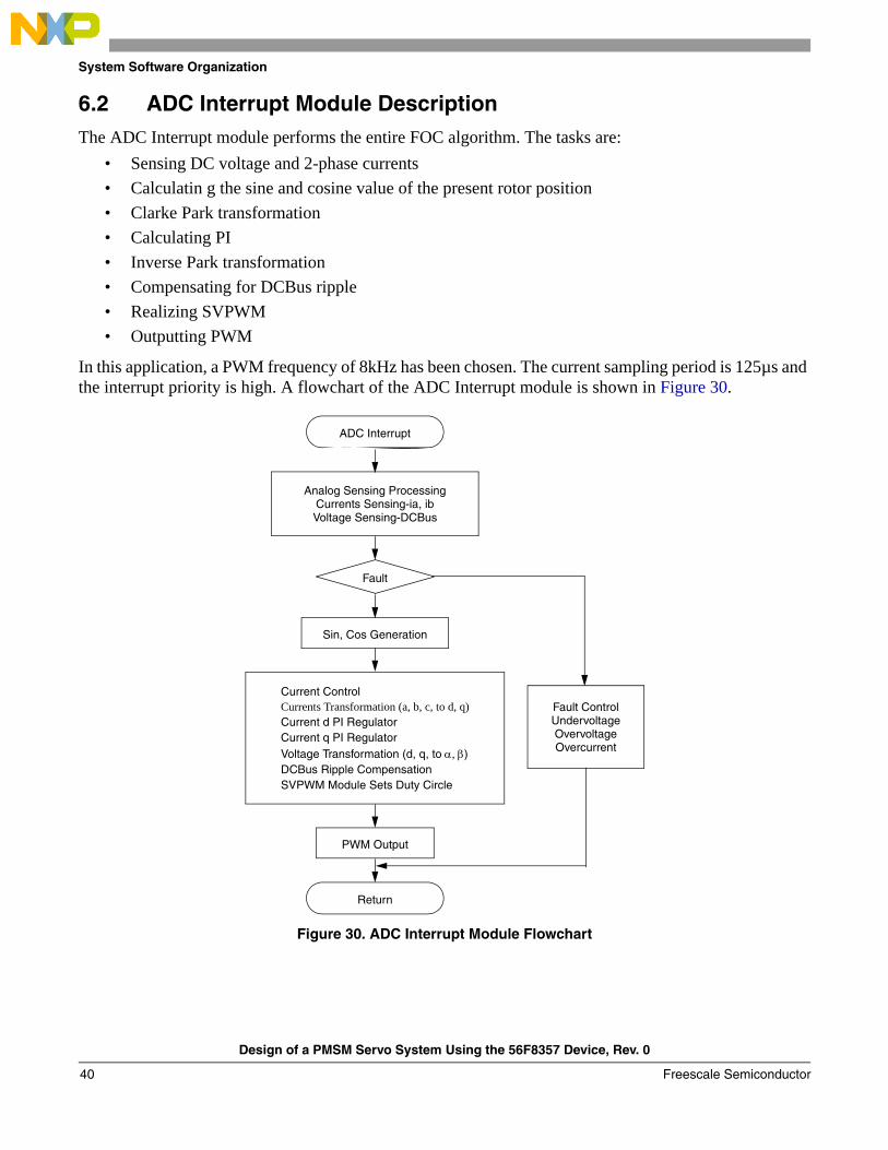
6.2 ADC Interrupt Module DescriptionThe ADC Interrupt module performs the entire FOC algorithm. The tasks are:
• Sensing DC voltage and 2-phase currents • Calculatin g the sine and cosine value of the present rotor position• Clarke Park transformation• Calculating PI • Inverse Park transformation• Compensating for DCBus ripple • Realizing SVPWM• Outputting PWM
In this application, a PWM frequency of 8kHz has been chosen. The current sampling period is 125µs and the interrupt priority is high. A flowchart of the ADC Interrupt module is shown in Figure 30.
Figure 30. ADC Interrupt Module Flowchart
ADC Interrupt
Analog Sensing ProcessingCurrents Sensing-ia, ibVoltage Sensing-DCBus
Fault
Sin, Cos Generation
Fault ControlUndervoltageOvervoltageOvercurrent
PWM Output
Return
Current ControlCurrents Transformation (a, b, c, to d, q)Current d PI RegulatorCurrent q PI RegulatorVoltage Transformation (d, q, to α, β)DCBus Ripple CompensationSVPWM Module Sets Duty Circle
Design of a PMSM Servo System Using the 56F8357 Device, Rev. 0
Freescale Semiconductor40
System Software Organization
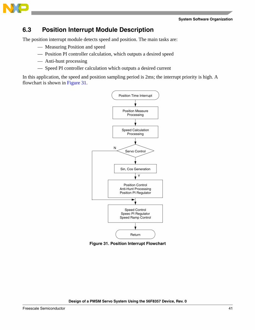
6.3 Position Interrupt Module DescriptionThe position interrupt module detects speed and position. The main tasks are:
— Measuring Position and speed — Position PI controller calculation, which outputs a desired speed— Anti-hunt processing— Speed PI controller calculation which outputs a desired current
In this application, the speed and position sampling period is 2ms; the interrupt priority is high. A flowchart is shown in Figure 31.
Figure 31. Position Interrupt Flowchart
Position Time Interrupt
Position MeasureProcessing
Speed CalculationProcessing
Servo ControlN
Y
Sin, Cos Generation
Position ControlAnti-Hunt ProcessingPosition PI Regulator
Speed ControlSpeec PI Regulator
Speed Ramp Control
Return
Design of a PMSM Servo System Using the 56F8357 Device, Rev. 0
Freescale Semiconductor 41
System Software Organization
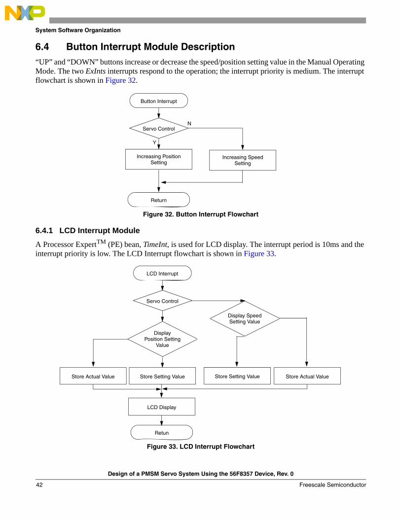
6.4 Button Interrupt Module Description“UP” and “DOWN” buttons increase or decrease the speed/position setting value in the Manual Operating Mode. The two ExInts interrupts respond to the operation; the interrupt priority is medium. The interrupt flowchart is shown in Figure 32.
Figure 32. Button Interrupt Flowchart
6.4.1 LCD Interrupt Module
A Processor ExpertTM (PE) bean, TimeInt, is used for LCD display. The interrupt period is 10ms and the interrupt priority is low. The LCD Interrupt flowchart is shown in Figure 33.
Figure 33. LCD Interrupt Flowchart
Button Interrupt
Servo ControlN
Y
Increasing PositionSetting
Increasing SpeedSetting
Return
LCD Interrupt
Servo Control
Display SpeedSetting Value
DisplayPosition Setting
Value
Store Actual Value Store Setting ValueStore Setting Value Store Actual Value
LCD Display
Retun
Design of a PMSM Servo System Using the 56F8357 Device, Rev. 0
Freescale Semiconductor42
Software Modules
7 Software ModulesProcessor Expert (PE) offers a wide variety of beans. In this system, the core modules and interface modules also use beans.
7.1 Core ModulesThe core modules execute the FOC’s varied tasks and include:
• Co-ordinate Transformations: Clarke-Park and Inverse Park• Transformation from α, β to d-q coordinates and backwards• Generation of sine and cosine with a look-up table• Variable stator voltage vector generation: Space Vector Modulation (SVM) algorithm• DC ripple compensation• Speed regulation, current regulation, position regulation• Speed ramp• Position alignment • Anti-Hunt processing
7.1.1 Clarke Transformation
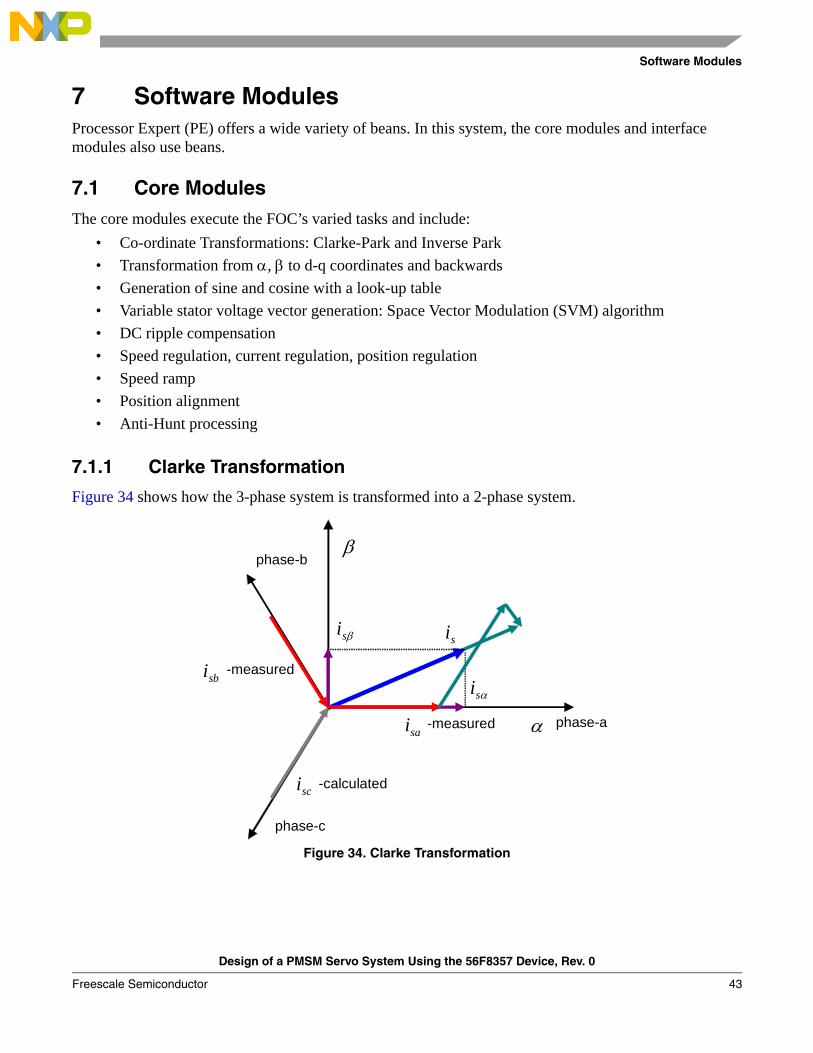
Figure 34 shows how the 3-phase system is transformed into a 2-phase system.
Figure 34. Clarke Transformation
α
β
βsi
αsi
si
phase-a
phase-c
phase-b
sai
sbi
sci -calculated
-measured
-measured
Design of a PMSM Servo System Using the 56F8357 Device, Rev. 0
Freescale Semiconductor 43

Software Modules
To transfer the graphical representation into mathematical language:
Eqn. 49
In most cases, the 3-phase system is symmetrical, which means that the sum of the phase quantities is always zero.
Eqn. 50
The constant “K” can be freely chosen and equalizing the ⟨-quantity and a-phase quantity is recommended.
Then:
Eqn. 51
The Clarke-Park transformation can be fully defined:
Eqn. 52
7.1.2 Transformation from α, β to d-q Coordinates and Backwards
Vector control is performed entirely in the d-q coordinate system to make the control of PM synchronous motors elegant and easy. Of course, this requires transformation in both directions and the control action must be transformed back to the motor side.
First, establish the d-q coordinate system:
Eqn. 53
Eqn. 54
Eqn. 55
⎥⎥⎥
⎦
⎤
⎢⎢⎢
⎣
⎡⋅
⎥⎥⎥⎥
⎦
⎤
⎢⎢⎢⎢
⎣
⎡
−
−−=⎥
⎦
⎤⎢⎣
⎡
cba
K
23
230
21
211
βα
aKcbacbaK230
21
21
==++=⎟⎠⎞
⎜⎝⎛ −−=α
32
=⇒= Kaα
⎥⎥⎥
⎦
⎤
⎢⎢⎢
⎣
⎡⋅
⎥⎥
⎦
⎤
⎢⎢
⎣
⎡
−==++=⎥⎥⎥
⎦
⎤
⎢⎢⎢
⎣
⎡⋅
⎥⎥⎥⎥
⎦
⎤
⎢⎢⎢⎢
⎣
⎡
−
−−=⎥
⎦
⎤⎢⎣
⎡
cba
cbacba
31
310
0010
31
310
31
31
32
βα
βα MMM Ψ+Ψ=Ψ
M
MField Ψ
Ψ= βθsin
M
MField Ψ
Ψ= αθcos
Design of a PMSM Servo System Using the 56F8357 Device, Rev. 0
Freescale Semiconductor44
Software Modules
Then transform from α, β to d-q coordinates:
Eqn. 56
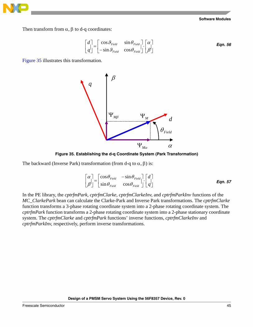
Figure 35 illustrates this transformation.
Figure 35. Establishing the d-q Coordinate System (Park Transformation)
The backward (Inverse Park) transformation (from d-q to α, β) is:
Eqn. 57
In the PE library, the cptrfmPark, cptrfmClarke, cptrfmClarkeInv, and cptrfmParkInv functions of the MC_ClarkePark bean can calculate the Clarke-Park and Inverse Park transformations. The cptrfmClarke function transforms a 3-phase rotating coordinate system into a 2-phase rotating coordinate system. The cptrfmPark function transforms a 2-phase rotating coordinate system into a 2-phase stationary coordinate system. The cptrfmClarke and cptrfmPark functions’ inverse functions, cptrfmClarkeInv and cptrfmParkInv, respectively, perform inverse transformations.
⎥⎦
⎤⎢⎣
⎡⋅⎥
⎦
⎤⎢⎣
⎡−
=⎥⎦
⎤⎢⎣
⎡βα
θθ
ϑϑ
Field
Field
Field
Field
qd
cossin
sincos
α
βq
dβMΨ
αMΨ
MΨ
Fieldθ
⎥⎦
⎤⎢⎣
⎡⋅⎥
⎦
⎤⎢⎣
⎡ −=⎥
⎦
⎤⎢⎣
⎡qd
Field
Field
Field
Field
θθ
θθ
βα
cossin
sincos
Design of a PMSM Servo System Using the 56F8357 Device, Rev. 0
Freescale Semiconductor 45

Software Modules
7.1.3 Generation of Sine, Cosine with a Look-up Table
The Park and Park-1 transformation use the value of the rotor electrical position to handle the stator current vector projection in a rotating frame.
To obtain both sine and cosine from the electrical angle, a sine look-up table, mcgenSineTable256, is used. The table contains 256 words to represent sine values of electrical angles in the range [0—360°]. As a result:
qe’s resolution is limited to 360/256 = .40625°qe = electrical angle / 360° (with qe in the range [0—FFFh]) qe varies from 0 to 4095 (See Section 5.6, “Position and Speed Sensing” for additional information about position sensing)
As only 256 words are available to represent this range, qe is divided by 16 and stored into the variable index that will be used to address the look-up table.
NOTETo calculate the cosine value of the electrical angle, add 90° to qe
7.1.4 Variable Stator Voltage Vector Generation: Space Vector Modulation Algorithm
The MC_SpaceVectorMod bean provides six usable PWM modes. The svmAlt algorithm is used in this system. A Space Vector Modulation is adopted, with nulls that are formed from states O000 in even sectors and O111 in odd sectors. The center-aligned PWM output is used at same time. The SetRatio15 of the PWMMC bean is adopted to output PWM.
7.1.5 DC Ripple Compensation
To eliminate the influence of DCBus voltage ripples on the generated PWM waveforms, the DC ripple compensation algorithm is used to compensate for the amplitude of the α and β components of the stator reference voltage vector, US. These imperfections are eliminated as shown in the following equations:
Eqn. 58
Where:Index must be within a fractional range and positive: 0 < Index < 1.The value depends on the modulation technique; i.e., for Space Vector Modulation techniques and Injection of the Third Harmonic, it is equal to 0.866025.
otherwise
dcbusuUIndexif
Usigndcbusu
UIndexU 2
_
0.1)(_
<∗
⎪⎩
⎪⎨⎧
∗
∗=∗ α
α
α
α
Design of a PMSM Servo System Using the 56F8357 Device, Rev. 0
Freescale Semiconductor46

Software Modules
The y = sign (x) function is defined as follows:
Eqn. 59
Where:x = Uα, Uβ are input duty-cycle ratios U*
α, U*β are output duty-cycle ratios.
In this system, the svmElimDCBusRip bean is adopted to compensate for DC voltage ripple.
7.1.6 Speed Regulation, Current Regulation, Position Regulation
PI control is applied in speed, current, and position control.
The expression of PI control is:
Eqn. 60
Where:u(t) is the controller’s output signale(t) is the controller’s input error signalKP is proportional factorT1 is the integral time constant
If the sampling period, T, is small enough, the discrete PI expression can be written:
Eqn. 61
Where:k is the sampling order numberu(k) is the controller’s output at the sampling time k. e(k) and e(k-1) are input errors at time k and k-1, respectivelyIntegral factor KI = T/T1.
The proportional term and the integral term, respectively, are responsible for error sensibility and for the steady state error.
The incremental form of the PI algorithm is expressed as:
Eqn. 62
otherwisexif
y0
0.10.1 ≥
⎩⎨⎧−
=
⎥⎦
⎤⎢⎣
⎡+= ∫
t
IP dtte
TteKtu
0)(1)()(
⎥⎦
⎤⎢⎣
⎡+= ∑
=
k
jIP jeKkeKku
0)()()(
[ ] )()1()()1()()( keKkekeKkukuku IP +−−=−−=Δ
Design of a PMSM Servo System Using the 56F8357 Device, Rev. 0
Freescale Semiconductor 47
Software Modules
One limit of the PI algorithm is that during normal operation, a large reference variation or disturbance may occur, resulting in saturation and overflow of the regulator variables and output. If uncontrolled, this kind of nonlinearity damages the system’s dynamic performance. One solution is to add a correction of the integral component to the previous structure.
The improved PI algorithm is:
Eqn. 63
Eqn. 64
Eqn. 65
Eqn. 66
Eqn. 67
The integral term:
Eqn. 68
Where:Integral correction factor Kc = KI / KP
The PItype1_asmSc provided by the PE library is used to calculate the PI controller output for speed, current, and position.
7.1.7 Speed Ramp
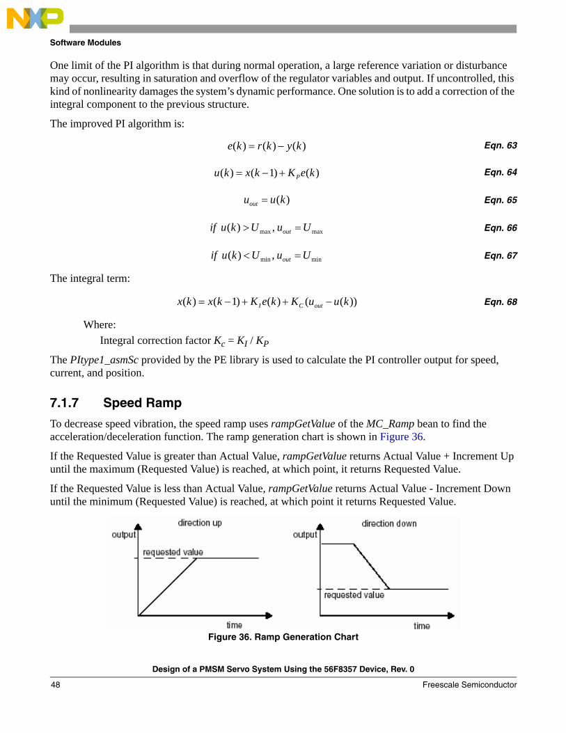
To decrease speed vibration, the speed ramp uses rampGetValue of the MC_Ramp bean to find the acceleration/deceleration function. The ramp generation chart is shown in Figure 36.
If the Requested Value is greater than Actual Value, rampGetValue returns Actual Value + Increment Up until the maximum (Requested Value) is reached, at which point, it returns Requested Value.
If the Requested Value is less than Actual Value, rampGetValue returns Actual Value - Increment Down until the minimum (Requested Value) is reached, at which point it returns Requested Value.
Figure 36. Ramp Generation Chart
)()()( kykrke −=
)()1()( keKkxku P+−=
)(kuuout =
maxmax ,)( UuUkuif out =>
minmin ,)( UuUkuif out =<
))(()()1()( kuuKkeKkxkx outCI −++−=
Design of a PMSM Servo System Using the 56F8357 Device, Rev. 0
Freescale Semiconductor48

Software Modules
7.1.8 Position Alignment
After reset, the rotor’s position is unknown. Vector control requires zero position, where the rotor is aligned to the d axis of the d-q coordinate system before a motor begins running, so the rotor must be aligned. The position is first set to zero, independent of the actual rotor position; the value of the Quadrature Encoder does not affect this setting. The Id current is then set to align rotor. The rotor is now aligned to the required position. After rotor stabilization, the Quadrature Encoder is reset to the zero position, the Id current is set back to zero, and alignment is complete. The rotor position is shown in Figure 37. Alignment is executed only once during the first transition from the Stop to the Run state of the Run/Stop switch.
Figure 37. Rotor Alignment
The TimeDate bean is used for rotor alignment. The rotor alignment period setting is 5s, and rotor alignment is accomplished during this period. Once the time is reached, the onAlarm function signals to denote the completion of rotor alignment.
7.1.9 Anti-Hunt Processing
Special attention is required when the motor reaches the required position, since the rotor will very likely oscillate (hunt). A variable-gain anti-hunt algorithm is developed. As shown in Figure 38, the speed and position regulators’ PI gains are kept normal when the position error is large. When the position error is small enough (in region 1 or 3), the gains should be gradually reduced. Once the rotor enters the anti-hunt window (region 2), the gains are reset to zero. This approach has effectively avoided the rotor oscillation at the stand-still position.
Figure 38. Anti-Hunt PI gain
α
β
q
d
MΨ0=Fieldθ
zero rotor position (aligned)
unknown rotor position (not aligned)
1 32
XPosition
P,I Gains
Design of a PMSM Servo System Using the 56F8357 Device, Rev. 0
Freescale Semiconductor 49

Software Modules
7.2 Interface ModulesInterface modules are lowlevel routines that convert real word data into suitable numerical counterparts. The interface modules include:
7.2.1 Current, Voltage Sensing
Sensing modules directly handle the hardware interface via the integrated peripherals; see Figure 23. Two LEMs (current-voltage transducer) sense the phase currents. The LEM converts the current information from phase a and b into voltage information. The voltage variety range is limited to [0—2.5V] to meet the input range of the 56F8357‘s ADC input voltage specification. Figure 39 illustrates the Current Sensing Scale Translation.
Figure 39. Current Sensing Scale Translation
GetChanValue of the ADC bean calculates a 15-bit sampling value. The sampling value subtracts the value corresponding to zero to find the actual value. These values are stored separately in i_abc.PhaseA, i_abc.PhaseB, and u_dc_bus.
7.2.2 Electrical Position and Mechanical Speed
The embedded encoder of this application generates 1024 pulses per mechanical revolution. The A, B, and Index quadrature signals from the position detection circuit (Figure 24) are shown in Figure 40. These signals are sent to the quadrature decoder port of the controller. The QuadratureDecoder bean converts the 1024p/c signal to 4096p/c. GetCounters retrieves the real time position and count difference. With these values, mechanical speed is calculated by the T method.
The Index signal also defines the zero position per rotation to count the position pulse.
Figure 40. Quatrature Encoder Signals
Phase current Binary
+5A
0A
-5A
3102
1551
0
Phase A Phase B
Index One revelution
4094 4095 0 1 4094 4095 0 1
Design of a PMSM Servo System Using the 56F8357 Device, Rev. 0
Freescale Semiconductor50

User Interface
8 User InterfacePC master software is programmed as the user interface to control motor and display variables. VBScript programs the HTML control interface. Figure 41 illustrates the PC master software interface.
Figure 41. PC Master Software Control Interface
Possible user commands, setting values, and actual values are displayed on the right half of the interface window. The commands include:
• Start motor• Stop motor• Increase setting value (UP)• Decrease setting value (DOWN)• PC master software control• Selection of position control/speed control• Position alignment
Design of a PMSM Servo System Using the 56F8357 Device, Rev. 0
Freescale Semiconductor 51
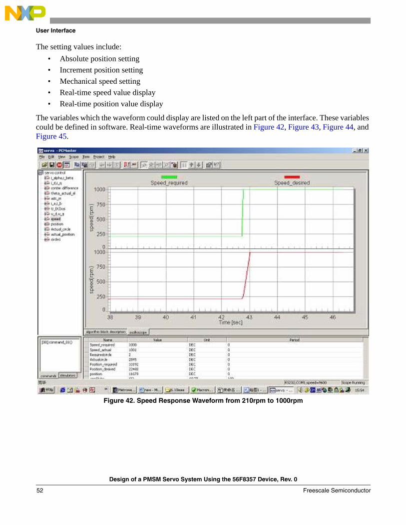
User Interface
The setting values include:• Absolute position setting• Increment position setting• Mechanical speed setting• Real-time speed value display• Real-time position value display
The variables which the waveform could display are listed on the left part of the interface. These variables could be defined in software. Real-time waveforms are illustrated in Figure 42, Figure 43, Figure 44, and Figure 45.
Figure 42. Speed Response Waveform from 210rpm to 1000rpm
Design of a PMSM Servo System Using the 56F8357 Device, Rev. 0
Freescale Semiconductor52
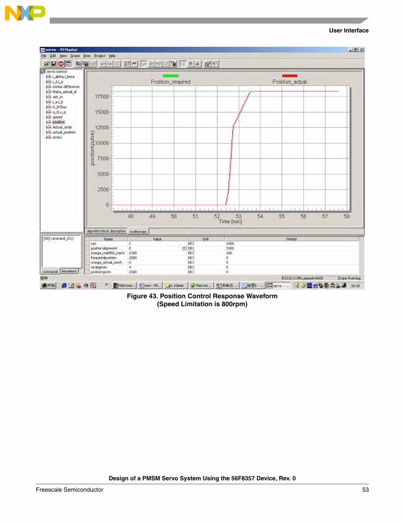
User Interface
Figure 43. Position Control Response Waveform(Speed Limitation is 800rpm)
Design of a PMSM Servo System Using the 56F8357 Device, Rev. 0
Freescale Semiconductor 53
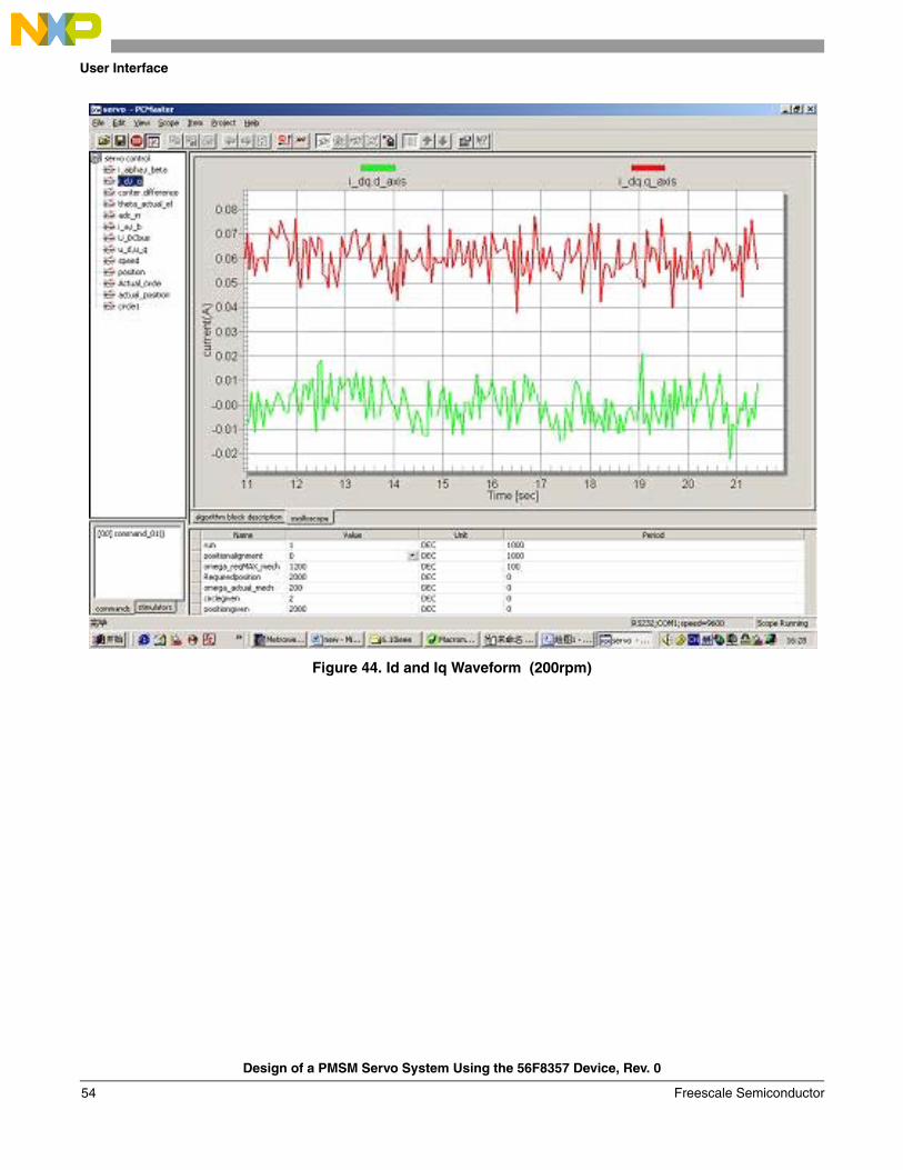
User Interface
Figure 44. Id and Iq Waveform (200rpm)
Design of a PMSM Servo System Using the 56F8357 Device, Rev. 0
Freescale Semiconductor54
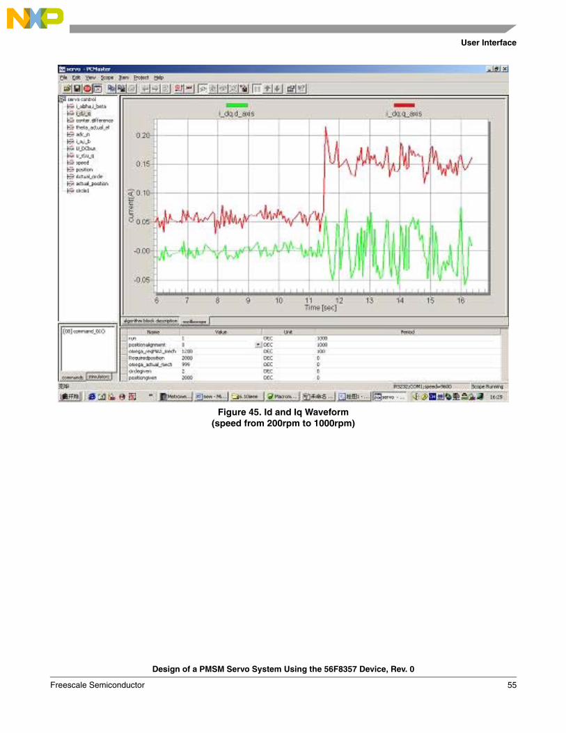
User Interface
Figure 45. Id and Iq Waveform (speed from 200rpm to 1000rpm)
Design of a PMSM Servo System Using the 56F8357 Device, Rev. 0
Freescale Semiconductor 55

Document Number: AN3301Rev. 008/2006
How to Reach Us:
Home Page:www.freescale.com
E-mail:[email protected]
USA/Europe or Locations Not Listed:Freescale SemiconductorTechnical Information Center, CH3701300 N. Alma School RoadChandler, Arizona 85224+1-800-521-6274 or [email protected]
Europe, Middle East, and Africa:Freescale Halbleiter Deutschland GmbHTechnical Information CenterSchatzbogen 781829 Muenchen, Germany+44 1296 380 456 (English)+46 8 52200080 (English)+49 89 92103 559 (German)+33 1 69 35 48 48 (French)[email protected]
Japan:Freescale Semiconductor Japan Ltd.HeadquartersARCO Tower 15F1-8-1, Shimo-Meguro, Meguro-ku,Tokyo 153-0064Japan0120 191014 or +81 3 5437 [email protected]
Asia/Pacific:Freescale Semiconductor Hong Kong Ltd.Technical Information Center2 Dai King StreetTai Po Industrial EstateTai Po, N.T., Hong Kong+800 2666 [email protected]
For Literature Requests Only:Freescale Semiconductor Literature Distribution CenterP.O. Box 5405Denver, Colorado 802171-800-441-2447 or 303-675-2140Fax: [email protected]
Information in this document is provided solely to enable system and software implementers to use Freescale Semiconductor products. There are no express or implied copyright licenses granted hereunder to design or fabricate any integrated circuits or integrated circuits based on the information in this document.
Freescale Semiconductor reserves the right to make changes without further notice to any products herein. Freescale Semiconductor makes no warranty, representation or guarantee regarding the suitability of its products for any particular purpose, nor does Freescale Semiconductor assume any liability arising out of the application or use of any product or circuit, and specifically disclaims any and all liability, including without limitation consequential or incidental damages. “Typical” parameters that may be provided in Freescale Semiconductor data sheets and/or specifications can and do vary in different applications and actual performance may vary over time. All operating parameters, including “Typicals”, must be validated for each customer application by customer’s technical experts. Freescale Semiconductor does not convey any license under its patent rights nor the rights of others. Freescale Semiconductor products are not designed, intended, or authorized for use as components in systems intended for surgical implant into the body, or other applications intended to support or sustain life, or for any other application in which the failure of the Freescale Semiconductor product could create a situation where personal injury or death may occur. Should Buyer purchase or use Freescale Semiconductor products for any such unintended or unauthorized application, Buyer shall indemnify and hold Freescale Semiconductor and its officers, employees, subsidiaries, affiliates, and distributors harmless against all claims, costs, damages, and expenses, and reasonable attorney fees arising out of, directly or indirectly, any claim of personal injury or death associated with such unintended or unauthorized use, even if such claim alleges that Freescale Semiconductor was negligent regarding the design or manufacture of the part.
Freescale™ and the Freescale logo are trademarks of Freescale Semiconductor, Inc. All other product or service names are the property of their respective owners.
© Freescale Semiconductor, Inc. 2006. All rights reserved.
RoHS-compliant and/or Pb-free versions of Freescale products have the functionality and electrical characteristics as their non-RoHS-compliant and/or non-Pb-free counterparts. For further information, see http://www.freescale.com or contact your Freescale sales representative.
For information on Freescale’s Environmental Products program, go to http://www.freescale.com/epp.