Embed Size (px)
Citation preview

Freescale SemiconductorApplication Note
© Freescale Semiconductor, Inc., 2008. All rights reserved.
The networking industry is constantly trying to get higher performance from systems. One popular technique is to simply increase the operating frequency of the processor. However, frequency can only be increased to the limit allowed by the processor technology. A second technique to boost performance is to increase the computing power of the processor by increasing the number of cores. Freescale Semiconductor has developed a dual-core E500 device based on the Power Architecture. The MPC8572E system on a chip (SOC) is the first such of a dual-core E500 device.
A dual-core SOC creates some challenges when booting a symmetric multi-processor (SMP) ready operating system (OS). This application note discusses the differences between SMP and AMP (asymmetric multi-processor) OSs, booting options and features of the MPC8572E, and configuration of shared and non-shared resources between cores. This application note also provides a description of the boot process implemented by Uboot and Linux that is provided as part of the MPC8572E development system board support package.
Document Number: AN3542Rev. 0, 1/2008
Contents1. Multi-core Operating System Architectures . . . . . . . . 22. Boot Options and Features . . . . . . . . . . . . . . . . . . . . . 33. Configuration of Resources . . . . . . . . . . . . . . . . . . . . 94. Linux Boot Process . . . . . . . . . . . . . . . . . . . . . . . . . . . 95. Revision History . . . . . . . . . . . . . . . . . . . . . . . . . . . . 10
SMP Boot Process for Dual E500 Coresby Ted Peters
NSD ApplicationsFreescale Semiconductor, Inc.Austin, TX

SMP Boot Process for Dual E500 Cores, Rev. 0
2 Freescale Semiconductor
Multi-core Operating System Architectures
1 Multi-core Operating System ArchitecturesThe MPC8572E is a dual-core E500 device based on the Power Architecture technology. To best utilize the two cores, operating systems choose one of two main architectures: symmetric multiprocessing or asymmetric multiprocessing. Which style to choose depends on the system application as the two architectures each have their pros and cons. In an SMP environment, a single OS image runs on each E500 core. In an AMP environment, two copies of a non-SMP OS may run, one copy on each E500 core. A second AMP environment example could be two unique OSs being run, one on each E500 core.
1.1 Symmetric MultiprocessingSymmetric multiprocessing (SMP) is a computer architecture where multiple cores within a single processor have a single, shared memory space. This approach allows the OS the ability to run a process on any core thereby giving the OS more flexibility in the distribution of workload.
The MPC8572E dual-core is able to run two processes simultaneously, one on each core. Not all programs will benefit from this parallelization. For this parallelization to be beneficial, programs must be written to be multithreaded. Multithreaded programs are written such that tasks are broken up into threads. With proper thread scheduling and synchronization, these threads can run simultaneously on each core, with the result being higher performance than if the task threads were run sequentially on a single core.
SMP advantages:• Programs must be written for multithreaded processing to benefit from the parallel nature of SMP.• If external interrupts are handled by a one core, existing programs that are not written to be
multithreaded may benefit by being run on the other core that does not get interrupted. These programs do not get suspended due to interrupts and have the potential for higher performance.
• The shared memory architecture allows a process to be run on any core at anytime.
SMP disadvantages:• Existing programs that were not written to be multithreaded may not benefit from the parallel
nature of SMP unless they are re-written.• A multithreaded program written for a SMP environment may not perform as well if run in a
single-core environment.• As the number of cores increases in a SMP environment, the overhead for scheduling and
synchronization between cores increase.• Cache coherency between the cores becomes a potential performance hit due to the shared memory
architecture.
1.2 Asymmetric MultiprocessingAsymmetric multiprocessing (AMP) is a computer architecture where multiple cores within a single processor each have a separate OS running, where the OS running on each core may or may not be the same OS. This approach allows each core/OS to have a specific specialized task. This gives the system the ability to dedicate resource efficiently. For example, one core may focus only on processing critical data while another core handles several less critical tasks.

SMP Boot Process for Dual E500 Cores, Rev. 0
Freescale Semiconductor 3
Boot Options and Features
AMP advantages:• Programs do not have be rewritten for multithreaded processing.• Easier to implement than a SMP operating system.• Resources are dedicated.
AMP disadvantages:• An individual task cannot split up to make use of an idle cpu.
2 Boot Options and FeaturesThe MPC8572E supports various boot features to allow greater flexibility how the device is initialized for boot and from where the device boots from. This section is discuss the default boot mode for a typical configuration as well as the additional boot options and features supported. The features primarily are used during power on reset and direct how each core is brought up and how it is initialized prior to being released from reset. Most features are enabled using power on reset input pins that are sampled during HRESET_ assertion, while others are controlled using the boot sequencer to initialize them prior to being released from reset.
2.1 Default BootThe MPC8572EDS default configuration employs the most common boot setup, but provides configuration options to enable many of the features described in this document. The default boot setup is to have the physical boot ROM location on the local bus, typically in NOR flash. The boot sequencer is not enabled to pre-initialized any registers in the MPC8572E prior to being release from reset. The cpu boot option is configured to only boot core0. Core0 is then responsible to configure the system and boot core1.
In this default configuration, core0 will fetch its initial instruction fetch at the reset vector located at 0x0_FFFF_FFFC. Instruction at the reset vector must be a branch to another address within the default 4K boot page. The default 4K boot page is preconfigure by hardware to be mapped by TLB1 entry 0 in each core. The instruction fetch performed by the core will access a 8MB default boot space pointing to a peripheral device specified during boot up, typically NOR flash on the local bus is specified. In addition to the default boot space mapping, a 1-MByte CCSRBAR space is mapped to 0x0_FF70_0000. The CCSRBAR defines a window used to access all memory-mapped configuration, control, and status registers. To access the CCSRBAR space from the core, a TLB entry must be defined to map the CCSRBAR. Additional TLB entries in each core must be setup to access beyond the 4K default TLB entry in the 8MB default boot space. L2 SRAM regions can be mapped using the L2 configuration registers. Access to the mapped L2 SRAM space must have associated TLB entries configured in any core that access the space. The L2 SRAM space does not require a local access window (LAW) to be configured.
Any memory region other than the default boot space, CCSR or internal L2 SRAM must be mapped in a local access window (LAW registers in the Local Access Register block) including spaces mapped by any inbound ATMU windows. Additionally, any address accessed by either core that is not in the default 4K boot page must have an associated TLB entry configured in the core performing the access.

SMP Boot Process for Dual E500 Cores, Rev. 0
4 Freescale Semiconductor
Boot Options and Features
NOTE
After the device has come out of reset, all POR configuration input values are latch in the POR Configuration Value Registers in the Global Utilities Register block. Software can read these registers to know how the POR inputs were configured.
2.2 Boot Sequencer
The MPC8572E provides the boot sequencer feature which allows the device to have configuration registers in the CCSRBAR space configure prior to the device fetching the reset vector. This essentially allows some amount of configuration to occur before the device boots. For example, the boot sequencer could configure the DDR interface such that when the device boots it has immediate read/write access to the DDR memory. The boot sequencer requires a specific programming format to be stored in the serial ROM on the I2C1 interface.
The boot sequencer is enabled with a power on reset input signal, cfg_boot_seq[0:1], which is sample at the negation of HRESET_. The boot sequencer is essentially a DMA engine that will read configuration data from a serial ROM that is located on the I2C1 interface. If the boot sequencer is enabled, the cores will be held in reset until the boot sequence has completed. Once the boot sequencer has completed, according to the CPU boot configuration signals, the allowed cores will fetch the boot code at the reset vector.
The boot sequencer is only able to write configuration data to the space pointed to by the CCSRBAR or by the alternate configuration space base address register (ALTCBAR). The ALTCBAR is a register in the CCSRBAR space that can be configured to allow access to a 1-MByte region of space anywhere in the memory map that is 1-MByte aligned. The ALTCBAR only allows access to 1-MByte of space at a time, it must be reconfigured to another 1-MByte space. For example, if the boot sequencer is programmed to initialize the DDR interface, it can then load the DDR memory 1-MByte at a time through the ALTCBAR 1-MByte window.
Table 1. Boot Sequencer Configuration
FunctionalSignal
Reset ConfigurationName
Value(Binary)
Meaning
LGPL3/LFWP, LGPL5
Default (11)
cfg_boot_seq[0:1] 00 Reserved
01 Normal I2C addressing mode is used. Boot sequencer is enabled and loads configuration information from a ROM on the I2C1 interface. A valid ROM must be present.
10 Extended I2C addressing mode is used. Boot sequencer is enabled and loads configuration information from a ROM on the I2C1 interface. A valid ROM must be present.
11 Boot sequencer is disabled. No I2C ROM is accessed (default).

SMP Boot Process for Dual E500 Cores, Rev. 0
Freescale Semiconductor 5
Boot Options and Features
2.3 Alternate Configuration SpaceWhen using the boot sequencer, the boot sequencer can access the 1-MByte CCSR space through the predefined CCSRBAR mapping. If the boot sequencer program configures any additional memory in the memory map, DDR memory for instance, the alternate configuration space is a feature that allows the boot sequencer to have access that DDR space.
The boot sequencer feature can access the entire memory space through the alternate configuration space base address register (ALTCBAR). The boot sequencer must first program the desired 1-MByte aligned value in the ALTCBAR register through its register offset in the CCSRBAR space. The boot sequencer must then enable the alternate configuration space by setting the alternate configuration attribute ALTCAR[EN] bit. The enable bit in the ALTCAR register should be cleared either by the boot sequencer or by the boot code that executes after the boot sequencer has completed its configuration operations. An alternate configuration space can be accessed by configuring the ALTCBAR and ALTCAR registers. The alternate configuration space is to be used with the boot sequencer to allow the boot sequencer to access an alternate 1-Mbyte region of configuration space. The value programmed into the ALTCBAR register will be combined with the 20-bit address offset in the boot sequencer program to generate a 36-bit address that is mapped to the target specified in ALTCAR. Thus, by configuring these registers, the boot sequencer has access to the entire memory map, one 1-Mbyte block at a time.
Table 2. ALTCBAR Bit Settings
Bits Name Description
0–7 — Write reserved, read = 0
8–23 BASE_ADDR Identifies the16 most significant address bits of an alternate window used for configuration accesses.
24–31 — Write reserved, read = 0
Table 3. ALTCAR Bit Settings
Bits Name Description
0 EN Enable for a second configuration window. Like CCSRBAR, it has a fixed size of 1 Mbyte.0 Second configuration window is disabled.1 Second configuration window is enabled.
1–6 — Write reserved, read = 0

SMP Boot Process for Dual E500 Cores, Rev. 0
6 Freescale Semiconductor
Boot Options and Features
2.4 Boot Page Translation
The MPC8572E provides a boot page translation feature which allows flexibility in where each e500 core will fetch the reset vector. Each core will default to boot from the configured 4-Kbyte page at 0x0_FFFF_Fnnn. Each core begins execution with the instruction at effective address 0x0_FFFF_FFFC, aka. the reset vector.
Boot page translation allows the flexibility to point either core anywhere in the 36-bit address space to fetch its reset vector. Boot page translation is controlled by the boot page translation register (BPTR). The boot page translation feature essentially take the boot address request by the core, strips the address down to 0xn_nnnn_nFFC, and replaces the 0xn_nnnn_n with the 24-bit BPTR[BOOT_PAGE] field. For example if BPTR[BOOT_PAGE]=0x123456, the resulting fetch address for the reset vector 0x0_FFFF_FFFC would be 0x1_2345_6FFC. This resulting address would need to be mapped in a local access window since it is not within the default 8MB boot ROM window. The the BPTR is configured to point outside of the default 8MB boot ROM address range at 0x0_FF80_0000 to 0x0_FFFF_FFFF, a local access window must be setup to cover the space and map the space to the target interface. The BPTR defines only the address translation, not the target interface window. The local access window can be configured by an external host or the boot sequencer while the cores are in boot holdoff mode. Another option is to boot one core, then let the boot code for that core reconfigure the BPTR and a local access window for the second core to boot from.
7–11 TRGT_ID Identifies the device ID to target when a transaction hits in the 1-Mbyte address range defined by the second configuration window.00000 PCI Express interface 300001 PCI Express interface 200010 PCI Express interface 100011 Reserved00100 Local bus controller00101–01010 Reserved01011 Interleaved DDR SDRAM01100 Serial RapidIO01101 Reserved 01110 Reserved 01111 DDR SDRAM interface 110000-10101 Reserved10110 DDR SDRAM interface 210111-11111 Reserved
12–31 — Write reserved, read = 0
Table 4. BPTR Bit Settings
Bits Name Description
0 EN Boot page translation enable for e500 core transactions0 Boot page is not translated.1 Boot page is translated as defined in the BPTR[BOOT_PAGE] parameter.
Table 3. ALTCAR Bit Settings (continued)
Bits Name Description

SMP Boot Process for Dual E500 Cores, Rev. 0
Freescale Semiconductor 7
Boot Options and Features
2.5 POR Configuration of Boot Location (ROM, DDR, PEX, etc.)The 85xx family of SOCs provides flexibility in where the physical location of the default boot address range. Typically the default boot ROM is located off of the local bus. The 85xx default boot ROM address range is defined to be 8 Mbytes at address 0x0_FF80_0000 to 0x0_FFFF_FFFF. However, which peripheral interface handles these boot ROM accesses can be selected at power on. An example usage of this feature would be to configure the boot ROM location to be off of the PCI Express 1 interface. The boot sequencer could be used to program the PEX1 interface prior to boot, the cfg_rom_loc[0:3] POR bits would be set to b’0000, and when the core boots it will fetch the reset vector from the PEX1 interface.
The boot ROM location inputs, shown in Table 5, select the physical location of boot ROM. Accesses to the boot vector and the default boot ROM region of the local address map are directed to the interface specified by these inputs.
The MPC8572EDS boot ROM location is selectable. The POR bits cfg_rom_loc[0:3] are controlled with a switch, with the board having a default switch setting of b’1110. This setting specifies that the default
1–7 — Write reserved, read = 0
8–31 BOOT_PAGE Translation for boot page. If enabled, the high order 24 bits of e500 core accesses to 0x0_FFFF_Fnnn are replaced with this value.
Table 5. Boot ROM Location
Functional Signals Reset Configuration NameValue
(Binary)Meaning
TSEC1_TXD[6:4], TSEC1_TX_ER
Default (1111)
cfg_rom_loc[0:3] 0000 PCI Express 1
0001 PCI Express 2
0010 Serial RapidIO
0011 Reserved
0100 DDR controller 1
0101 DDR controller 2
0110 DDR Interleaved
0111 PCI Express 3
1000 Local bus FCM--8-bit NAND Flash small page
1001 Reserved
1010 Local bus FCM--8-bit NAND Flash large page
1011 Reserved
1100 Reserved
1101 Local bus GPCM—8-bit ROM
1110 Local bus GPCM—16-bit ROM
1111 Local Bus GPCM—32-bit ROM (default)
Table 4. BPTR Bit Settings
Bits Name Description

SMP Boot Process for Dual E500 Cores, Rev. 0
8 Freescale Semiconductor
Boot Options and Features
boot ROM location is the Local Bus GPCM 16-bit ROM. The boot ROM location can also be configure to boot from all of the supported interfaces listed in Table 5.
In boot hold-off mode (cfg_cpu_boot = 0), the core is prevented from fetching its first instruction by withholding its internal bus grant. During this time, the PCI Express interface accepts all inbound PCI Express configuration transactions which allows an external host/RC to configure the device. When the external host/RC has configured the device to a state where it can allow the core to fetch code from the boot vector, it sets the MCMPCR[PORT0_EN] bit after which the core is granted the internal bus.
2.6 CPU Boot ConfigurationThe 85xx provides control over when each core in a multi-core SOC is allowed to boot. CPU boot configuration defines how each core is brought out of the reset state. It is possible to put either core or all cores in a boot holdoff mode. Boot holdoff mode will prevent a core from booting, for example, the core will not be permitted to fetch the reset vector. This feature can be used to allow external masters to configure the SOC to some desired state, then release one or more cores from boot holdoff. Another usage is to allow one core to boot and configure the SOC to the desired state, then release remaining cores to boot in the already configured environment.
The CPU boot configuration inputs, shown in Table 6, specify the boot configuration mode. If LA[27] is sampled low at reset, e500 core 0 is prevented from fetching boot code until configuration by an external master is complete. Similarly, EC3_MDC can be used to gate off e500 core 1 from fetching boot code. The external master frees e500 core 0 and/or core 1 to boot by setting EEBPCR[CPU0_EN] and/or EEBPCR[CPU1_EN], for core 0 and 1 respectively, in the ECM CCB port configuration register (EEBPCR).
The MPC8572EDS CPU boot configuration is selectable. Both LA[27] and EC3_MDC are each controlled with a switch, with the board having a default switch setting of b’10. This setting allows e500 core 0 is allowed to boot without waiting for configuration by an external master, while e500 core 1 is prevented from booting until configured by an external master or the other core. Software which boots on core 0 or an external master is responsible for releasing core 1 from boot holdoff mode via the EEPBPCR[CPU1_EN] bit field.
Table 6. CPU Boot Configuration
FunctionalSignal
Reset Configuration Name
Value(Binary)
Meaning
LA[27], EC3_MDC
Default (11)
cfg_cpu0_boot, cfg_cpu1_boot
00 CPU boot holdoff mode for both cores. The e500 cores are prevented from booting until configured by an external master.
01 e500 core 1 is allowed to boot without waiting for configuration by an external master, while e500 core 0 is prevented from booting until configured by an external master or the other core.
10 e500 core 0 is allowed to boot without waiting for configuration by an external master, while e500 core 1 is prevented from booting until configured by an external master or the other core.
11 Both e500 cores are allowed to boot without waiting for configuration by an external master (default).
SMP Boot Process for Dual E500 Cores, Rev. 0
Freescale Semiconductor 9
Configuration of Resources
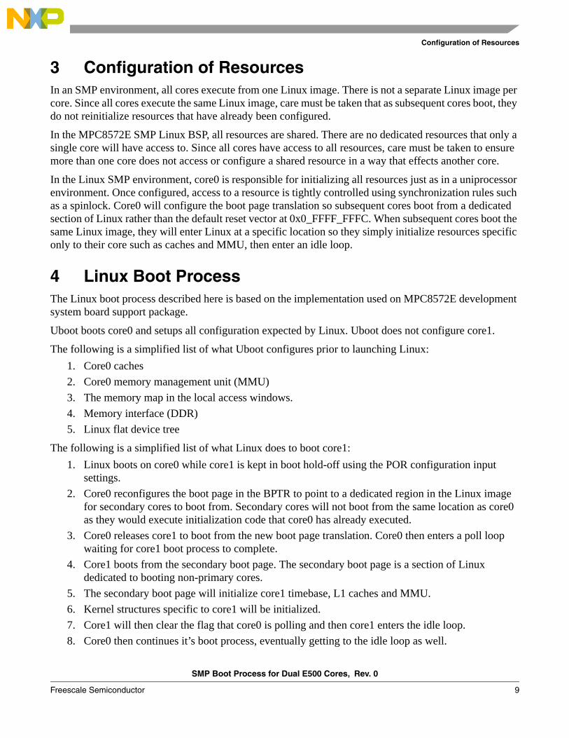
3 Configuration of ResourcesIn an SMP environment, all cores execute from one Linux image. There is not a separate Linux image per core. Since all cores execute the same Linux image, care must be taken that as subsequent cores boot, they do not reinitialize resources that have already been configured.
In the MPC8572E SMP Linux BSP, all resources are shared. There are no dedicated resources that only a single core will have access to. Since all cores have access to all resources, care must be taken to ensure more than one core does not access or configure a shared resource in a way that effects another core.
In the Linux SMP environment, core0 is responsible for initializing all resources just as in a uniprocessor environment. Once configured, access to a resource is tightly controlled using synchronization rules such as a spinlock. Core0 will configure the boot page translation so subsequent cores boot from a dedicated section of Linux rather than the default reset vector at 0x0_FFFF_FFFC. When subsequent cores boot the same Linux image, they will enter Linux at a specific location so they simply initialize resources specific only to their core such as caches and MMU, then enter an idle loop.
4 Linux Boot ProcessThe Linux boot process described here is based on the implementation used on MPC8572E development system board support package.
Uboot boots core0 and setups all configuration expected by Linux. Uboot does not configure core1.
The following is a simplified list of what Uboot configures prior to launching Linux:1. Core0 caches2. Core0 memory management unit (MMU)3. The memory map in the local access windows.4. Memory interface (DDR)5. Linux flat device tree
The following is a simplified list of what Linux does to boot core1:1. Linux boots on core0 while core1 is kept in boot hold-off using the POR configuration input
settings.2. Core0 reconfigures the boot page in the BPTR to point to a dedicated region in the Linux image
for secondary cores to boot from. Secondary cores will not boot from the same location as core0 as they would execute initialization code that core0 has already executed.
3. Core0 releases core1 to boot from the new boot page translation. Core0 then enters a poll loop waiting for core1 boot process to complete.
4. Core1 boots from the secondary boot page. The secondary boot page is a section of Linux dedicated to booting non-primary cores.
5. The secondary boot page will initialize core1 timebase, L1 caches and MMU.6. Kernel structures specific to core1 will be initialized.7. Core1 will then clear the flag that core0 is polling and then core1 enters the idle loop.8. Core0 then continues it’s boot process, eventually getting to the idle loop as well.

SMP Boot Process for Dual E500 Cores, Rev. 0
10 Freescale Semiconductor
Revision History
5 Revision History Table 7 provides a revision history for this application note. Note that this revision history table reflects the changes to this application note template, but can also be used for the application note revision history.
Table 7. Document Revision History
Rev.Number
Date Substantive Change(s)
0 01/2008 Initial release

SMP Boot Process for Dual E500 Cores, Rev. 0
Freescale Semiconductor 11
Revision History
THIS PAGE INTENTIONALLY LEFT BLANK

Document Number: AN3542Rev. 01/2008
Information in this document is provided solely to enable system and software
implementers to use Freescale Semiconductor products. There are no express or
implied copyright licenses granted hereunder to design or fabricate any integrated
circuits or integrated circuits based on the information in this document.
Freescale Semiconductor reserves the right to make changes without further notice to
any products herein. Freescale Semiconductor makes no warranty, representation or
guarantee regarding the suitability of its products for any particular purpose, nor does
Freescale Semiconductor assume any liability arising out of the application or use of
any product or circuit, and specifically disclaims any and all liability, including without
limitation consequential or incidental damages. “Typical” parameters which may be
provided in Freescale Semiconductor data sheets and/or specifications can and do
vary in different applications and actual performance may vary over time. All operating
parameters, including “Typicals” must be validated for each customer application by
customer’s technical experts. Freescale Semiconductor does not convey any license
under its patent rights nor the rights of others. Freescale Semiconductor products are
not designed, intended, or authorized for use as components in systems intended for
surgical implant into the body, or other applications intended to support or sustain life,
or for any other application in which the failure of the Freescale Semiconductor product
could create a situation where personal injury or death may occur. Should Buyer
purchase or use Freescale Semiconductor products for any such unintended or
unauthorized application, Buyer shall indemnify and hold Freescale Semiconductor
and its officers, employees, subsidiaries, affiliates, and distributors harmless against all
claims, costs, damages, and expenses, and reasonable attorney fees arising out of,
directly or indirectly, any claim of personal injury or death associated with such
unintended or unauthorized use, even if such claim alleges that Freescale
Semiconductor was negligent regarding the design or manufacture of the part.
How to Reach Us:
Home Page: www.freescale.com
Web Support: http://www.freescale.com/support
USA/Europe or Locations Not Listed: Freescale Semiconductor, Inc.Technical Information Center, EL5162100 East Elliot Road Tempe, Arizona 85284 +1-800-521-6274 or+1-480-768-2130www.freescale.com/support
Europe, Middle East, and Africa:Freescale Halbleiter Deutschland GmbHTechnical Information CenterSchatzbogen 781829 Muenchen, Germany+44 1296 380 456 (English) +46 8 52200080 (English)+49 89 92103 559 (German)+33 1 69 35 48 48 (French) www.freescale.com/support
Japan: Freescale Semiconductor Japan Ltd. HeadquartersARCO Tower 15F1-8-1, Shimo-Meguro, Meguro-ku Tokyo 153-0064Japan 0120 191014 or+81 3 5437 [email protected]
Asia/Pacific: Freescale Semiconductor Hong Kong Ltd. Technical Information Center2 Dai King Street Tai Po Industrial Estate Tai Po, N.T., Hong Kong +800 2666 [email protected]
For Literature Requests Only:Freescale Semiconductor
Literature Distribution Center P.O. Box 5405Denver, Colorado 80217 +1-800 441-2447 or+1-303-675-2140Fax: +1-303-675-2150LDCForFreescaleSemiconductor
@hibbertgroup.com
Freescale™ and the Freescale logo are trademarks of Freescale Semiconductor, Inc. The Power Architecture and Power.org word marks and the Power and Power.org logos and related marks are trademarks and service marks licensed by Power.org. All other product or service names are the property of their respective owners.
© Freescale Semiconductor, Inc., 2008. Printed in the United States of America. All rights reserved.


![E500 User Manual V1.0 202012 [ENG] - Geo-matching · 2021. 1. 28. · E500 User Manual Web: Email: support@esurvey-gnss.com 1.5 Power button There is a power button on E500 control](https://img.pdfslide.net/doc/110x75/613443dadfd10f4dd73b9eac/e500-user-manual-v10-202012-eng-geo-matching-2021-1-28-e500-user-manual.jpg)


![E500 Datasheet 20201111 [ENG]](https://img.pdfslide.net/doc/110x75/61f870f4db762243b65881d6/e500-datasheet-20201111-eng.jpg)


![Compaq Armada E500 V300[1]](https://img.pdfslide.net/doc/110x75/577d1f4e1a28ab4e1e90511a/compaq-armada-e500-v3001.jpg)