Embed Size (px)
Citation preview
March 2016 DocID023110 Rev 3 1/38
1
AN4099Application note
Implementation of transmitters and receivers for infrared remote control protocols with MCUs of the STM32F0 and STM32F3 Series
Introduction
Infrared radiation is the region of the electromagnetic spectrum that lies between microwaves and visible light.
Infrared radiation has two ranges: near infrared light is closest in wavelength to visible light, while far infrared is closer to the microwave region of the electromagnetic spectrum.
The shorter waves are the ones used by remote controls. Information is transmitted and received using electromagnetic energy, without using wires.
Infrared technology offers important advantages as a form of wireless communication. Nowadays, almost all audio and video equipment can be controlled using an infrared remote control. At the receiving end, a receiver detects the light pulses, which are processed to retrieve/decode the information they contain.
There are many popular infrared protocol standards used to transmit data via infrared light, such as RC5 and SIRC.
The purpose of this application note is to provide a generic solution for implementing an IR transmitter (a remote control device) and receiver in software using microcontrollers of the STM32F0 and STM32F3 Series. An example of software implementation is provided for RC5 and SIRC protocols. Other protocols are supported and available upon request (for further information contact the local STMicroelectronics sales office).
Note: The infrared transmitter and receiver solutions described in this document are implemented in C language and are available within the STM320518-EVAL (Config2), STM32373C-EVAL and STM32303C-EVAL packages available on www.st.com.
www.st.com
Contents AN4099
2/38 DocID023110 Rev 3
Contents
1 Infrared protocol specification . . . . . . . . . . . . . . . . . . . . . . . . . . . . . . . . . 6
1.1 RC5 protocol basics . . . . . . . . . . . . . . . . . . . . . . . . . . . . . . . . . . . . . . . . . . 6
1.2 SIRC protocol basics . . . . . . . . . . . . . . . . . . . . . . . . . . . . . . . . . . . . . . . . . 7
2 Infrared transmitter . . . . . . . . . . . . . . . . . . . . . . . . . . . . . . . . . . . . . . . . . 10
2.1 Hardware considerations . . . . . . . . . . . . . . . . . . . . . . . . . . . . . . . . . . . . . 10
2.2 IR transmitter: universal solution . . . . . . . . . . . . . . . . . . . . . . . . . . . . . . . .11
2.2.1 RC5 encoder solution . . . . . . . . . . . . . . . . . . . . . . . . . . . . . . . . . . . . . . 13
2.2.2 How to use the RC5 encoder driver . . . . . . . . . . . . . . . . . . . . . . . . . . . . 15
2.2.3 SIRC encoder solution . . . . . . . . . . . . . . . . . . . . . . . . . . . . . . . . . . . . . . 16
2.2.4 How to use the SIRC encoder driver . . . . . . . . . . . . . . . . . . . . . . . . . . . 17
3 Infrared receiver . . . . . . . . . . . . . . . . . . . . . . . . . . . . . . . . . . . . . . . . . . . 18
3.1 Hardware considerations . . . . . . . . . . . . . . . . . . . . . . . . . . . . . . . . . . . . . 18
3.2 Universal solution: software implementation using a GP-Timer configured in PWM input mode . . . . . . . . . . . . . . . . . . . . . . . . 18
3.3 RC5 protocol solutions . . . . . . . . . . . . . . . . . . . . . . . . . . . . . . . . . . . . . . . 20
3.3.1 RC5 frame decoding mechanism . . . . . . . . . . . . . . . . . . . . . . . . . . . . . 20
3.3.2 RC5 decoding library . . . . . . . . . . . . . . . . . . . . . . . . . . . . . . . . . . . . . . . 23
3.3.3 How to use the RC5 decoder driver . . . . . . . . . . . . . . . . . . . . . . . . . . . . 24
3.4 SIRC infrared control solution . . . . . . . . . . . . . . . . . . . . . . . . . . . . . . . . . 26
3.4.1 Software implementation . . . . . . . . . . . . . . . . . . . . . . . . . . . . . . . . . . . . 26
3.4.2 SIRC library . . . . . . . . . . . . . . . . . . . . . . . . . . . . . . . . . . . . . . . . . . . . . . 28
3.4.3 How to use the SIRC decoder driver . . . . . . . . . . . . . . . . . . . . . . . . . . . 28
4 Interface layer . . . . . . . . . . . . . . . . . . . . . . . . . . . . . . . . . . . . . . . . . . . . . 31
4.1 Demonstration programs . . . . . . . . . . . . . . . . . . . . . . . . . . . . . . . . . . . . . 31
4.1.1 Transmitter demonstration using IRTIM . . . . . . . . . . . . . . . . . . . . . . . . . 31
4.1.2 Receiver demonstration using GP-Timer configured in PWM mode . . . 32
4.2 How to customize the IR drivers . . . . . . . . . . . . . . . . . . . . . . . . . . . . . . . . 33
4.2.1 IR receiver drivers . . . . . . . . . . . . . . . . . . . . . . . . . . . . . . . . . . . . . . . . . 33
4.2.2 IR transmitter drivers . . . . . . . . . . . . . . . . . . . . . . . . . . . . . . . . . . . . . . . 35
5 Conclusion . . . . . . . . . . . . . . . . . . . . . . . . . . . . . . . . . . . . . . . . . . . . . . . . 36
DocID023110 Rev 3 3/38
AN4099 Contents
3
6 Revision history . . . . . . . . . . . . . . . . . . . . . . . . . . . . . . . . . . . . . . . . . . . 37
List of tables AN4099
4/38 DocID023110 Rev 3
List of tables
Table 1. RC5 timings . . . . . . . . . . . . . . . . . . . . . . . . . . . . . . . . . . . . . . . . . . . . . . . . . . . . . . . . . . . . . 7Table 2. SIRC timings. . . . . . . . . . . . . . . . . . . . . . . . . . . . . . . . . . . . . . . . . . . . . . . . . . . . . . . . . . . . . 9Table 3. Example of implementation . . . . . . . . . . . . . . . . . . . . . . . . . . . . . . . . . . . . . . . . . . . . . . . . 25Table 4. Example of implementation . . . . . . . . . . . . . . . . . . . . . . . . . . . . . . . . . . . . . . . . . . . . . . . . 29Table 5. List of defines in the header file for the IR protocol parameters . . . . . . . . . . . . . . . . . . . . . 34Table 6. Document revision history . . . . . . . . . . . . . . . . . . . . . . . . . . . . . . . . . . . . . . . . . . . . . . . . . 37
DocID023110 Rev 3 5/38
AN4099 List of figures
5
List of figures
Figure 1. RC5 bit representation . . . . . . . . . . . . . . . . . . . . . . . . . . . . . . . . . . . . . . . . . . . . . . . . . . . . . 6Figure 2. Example of an RC5 frame . . . . . . . . . . . . . . . . . . . . . . . . . . . . . . . . . . . . . . . . . . . . . . . . . . 6Figure 3. RC5 idle time . . . . . . . . . . . . . . . . . . . . . . . . . . . . . . . . . . . . . . . . . . . . . . . . . . . . . . . . . . . . 7Figure 4. Length of logical bits . . . . . . . . . . . . . . . . . . . . . . . . . . . . . . . . . . . . . . . . . . . . . . . . . . . . . . 8Figure 5. Length of start bit . . . . . . . . . . . . . . . . . . . . . . . . . . . . . . . . . . . . . . . . . . . . . . . . . . . . . . . . . 8Figure 6. Example of SIRC frame . . . . . . . . . . . . . . . . . . . . . . . . . . . . . . . . . . . . . . . . . . . . . . . . . . . . 8Figure 7. Hardware configuration for infrared transmitter . . . . . . . . . . . . . . . . . . . . . . . . . . . . . . . . . 10Figure 8. Hardware description . . . . . . . . . . . . . . . . . . . . . . . . . . . . . . . . . . . . . . . . . . . . . . . . . . . . . 10Figure 9. Main loop flowchart . . . . . . . . . . . . . . . . . . . . . . . . . . . . . . . . . . . . . . . . . . . . . . . . . . . . . . . 12Figure 10. Send IR frame flowchart . . . . . . . . . . . . . . . . . . . . . . . . . . . . . . . . . . . . . . . . . . . . . . . . . . . 13Figure 11. RC5 send frame flowchart . . . . . . . . . . . . . . . . . . . . . . . . . . . . . . . . . . . . . . . . . . . . . . . . . 14Figure 12. Manchester encoding bits . . . . . . . . . . . . . . . . . . . . . . . . . . . . . . . . . . . . . . . . . . . . . . . . . . 14Figure 13. SIRC send frame flowchart . . . . . . . . . . . . . . . . . . . . . . . . . . . . . . . . . . . . . . . . . . . . . . . . . 16Figure 14. SIRC logical bit conversion. . . . . . . . . . . . . . . . . . . . . . . . . . . . . . . . . . . . . . . . . . . . . . . . . 17Figure 15. Hardware configuration. . . . . . . . . . . . . . . . . . . . . . . . . . . . . . . . . . . . . . . . . . . . . . . . . . . . 18Figure 16. Infrared decoding flowchart . . . . . . . . . . . . . . . . . . . . . . . . . . . . . . . . . . . . . . . . . . . . . . . . 19Figure 17. RC5 frame decoding mechanism . . . . . . . . . . . . . . . . . . . . . . . . . . . . . . . . . . . . . . . . . . . . 20Figure 18. Bit determination by the rising edge: low pulse . . . . . . . . . . . . . . . . . . . . . . . . . . . . . . . . . 21Figure 19. Bit determination by the falling edge: high pulse . . . . . . . . . . . . . . . . . . . . . . . . . . . . . . . . 22Figure 20. RC5 solution flowchart . . . . . . . . . . . . . . . . . . . . . . . . . . . . . . . . . . . . . . . . . . . . . . . . . . . . 23Figure 21. SIRC frame reception mechanism . . . . . . . . . . . . . . . . . . . . . . . . . . . . . . . . . . . . . . . . . . . 26Figure 22. SIRC solution flowchart . . . . . . . . . . . . . . . . . . . . . . . . . . . . . . . . . . . . . . . . . . . . . . . . . . . 27Figure 23. Application layer architecture . . . . . . . . . . . . . . . . . . . . . . . . . . . . . . . . . . . . . . . . . . . . . . . 31Figure 24. IR transmitter demo . . . . . . . . . . . . . . . . . . . . . . . . . . . . . . . . . . . . . . . . . . . . . . . . . . . . . . 32Figure 25. RC5 received frame shown in the LCD . . . . . . . . . . . . . . . . . . . . . . . . . . . . . . . . . . . . . . . 32
Infrared protocol specification AN4099
6/38 DocID023110 Rev 3
1 Infrared protocol specification
1.1 RC5 protocol basics
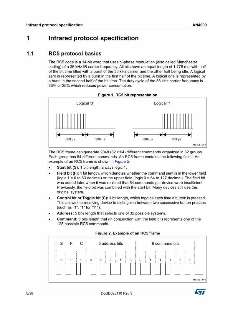
The RC5 code is a 14-bit word that uses bi-phase modulation (also called Manchester coding) of a 36 kHz IR carrier frequency. All bits have an equal length of 1.778 ms, with half of the bit time filled with a burst of the 36 kHz carrier and the other half being idle. A logical zero is represented by a burst in the first half of the bit time. A logical one is represented by a burst in the second half of the bit time. The duty cycle of the 36 kHz carrier frequency is 33% or 25% which reduces power consumption.
Figure 1. RC5 bit representation
The RC5 frame can generate 2048 (32 x 64) different commands organized in 32 groups. Each group has 64 different commands. An RC5 frame contains the following fields. An example of an RC5 frame is shown in Figure 2.
• Start bit (S): 1 bit length, always logic 1.
• Field bit (F): 1 bit length, which denotes whether the command sent is in the lower field (logic 1 = 0 to 63 decimal) or the upper field (logic 0 = 64 to 127 decimal). The field bit was added later when it was realized that 64 commands per device were insufficient. Previously, the field bit was combined with the start bit. Many devices still use this original system.
• Control bit or Toggle bit (C): 1 bit length, which toggles each time a button is pressed. This allows the receiving device to distinguish between two successive button presses (such as "1", "1" for "11").
• Address: 5 bits length that selects one of 32 possible systems.
• Command: 6 bits length that (in conjunction with the field bit) represents one of the 128 possible RC5 commands.
Figure 2. Example of an RC5 frame
DocID023110 Rev 3 7/38
AN4099 Infrared protocol specification
37
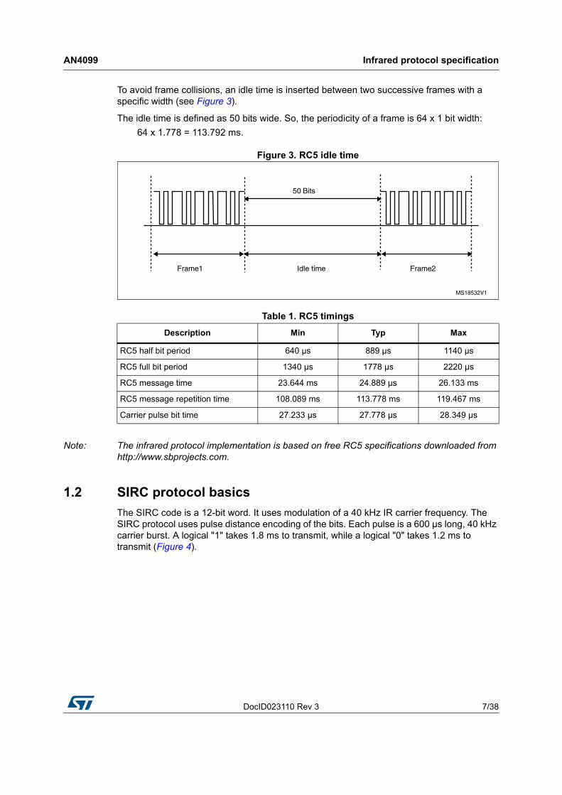
To avoid frame collisions, an idle time is inserted between two successive frames with a specific width (see Figure 3).
The idle time is defined as 50 bits wide. So, the periodicity of a frame is 64 x 1 bit width:
64 x 1.778 = 113.792 ms.
Figure 3. RC5 idle time
Note: The infrared protocol implementation is based on free RC5 specifications downloaded from http://www.sbprojects.com.
1.2 SIRC protocol basics
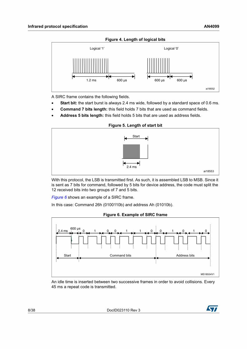
The SIRC code is a 12-bit word. It uses modulation of a 40 kHz IR carrier frequency. The SIRC protocol uses pulse distance encoding of the bits. Each pulse is a 600 µs long, 40 kHz carrier burst. A logical "1" takes 1.8 ms to transmit, while a logical "0" takes 1.2 ms to transmit (Figure 4).
Table 1. RC5 timings
Description Min Typ Max
RC5 half bit period 640 µs 889 µs 1140 µs
RC5 full bit period 1340 µs 1778 µs 2220 µs
RC5 message time 23.644 ms 24.889 µs 26.133 ms
RC5 message repetition time 108.089 ms 113.778 ms 119.467 ms
Carrier pulse bit time 27.233 µs 27.778 µs 28.349 µs
Infrared protocol specification AN4099
8/38 DocID023110 Rev 3
Figure 4. Length of logical bits
A SIRC frame contains the following fields.
• Start bit: the start burst is always 2.4 ms wide, followed by a standard space of 0.6 ms.
• Command 7 bits length: this field holds 7 bits that are used as command fields.
• Address 5 bits length: this field holds 5 bits that are used as address fields.
Figure 5. Length of start bit
With this protocol, the LSB is transmitted first. As such, it is assembled LSB to MSB. Since it is sent as 7 bits for command, followed by 5 bits for device address, the code must split the 12 received bits into two groups of 7 and 5 bits.
Figure 6 shows an example of a SIRC frame.
In this case: Command 26h (0100110b) and address Ah (01010b).
Figure 6. Example of SIRC frame
An idle time is inserted between two successive frames in order to avoid collisions. Every 45 ms a repeat code is transmitted.
DocID023110 Rev 3 9/38
AN4099 Infrared protocol specification
37
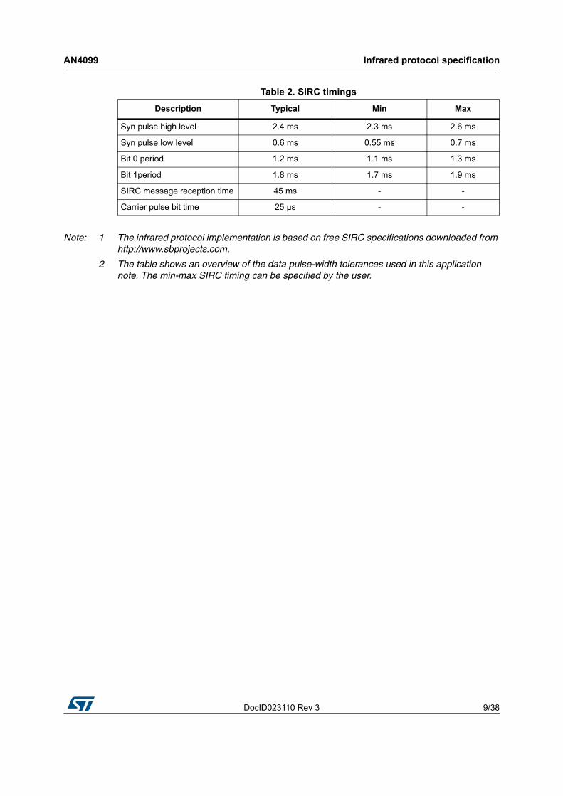
Note: 1 The infrared protocol implementation is based on free SIRC specifications downloaded from http://www.sbprojects.com.
2 The table shows an overview of the data pulse-width tolerances used in this application note. The min-max SIRC timing can be specified by the user.
Table 2. SIRC timings
Description Typical Min Max
Syn pulse high level 2.4 ms 2.3 ms 2.6 ms
Syn pulse low level 0.6 ms 0.55 ms 0.7 ms
Bit 0 period 1.2 ms 1.1 ms 1.3 ms
Bit 1period 1.8 ms 1.7 ms 1.9 ms
SIRC message reception time 45 ms - -
Carrier pulse bit time 25 µs - -
Infrared transmitter AN4099
10/38 DocID023110 Rev 3
2 Infrared transmitter
2.1 Hardware considerations
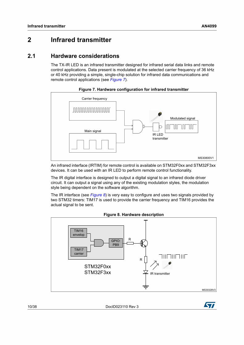
The TX-IR LED is an infrared transmitter designed for infrared serial data links and remote control applications. Data present is modulated at the selected carrier frequency of 36 kHz or 40 kHz providing a simple, single-chip solution for infrared data communications and remote control applications (see Figure 7).
Figure 7. Hardware configuration for infrared transmitter
An infrared interface (IRTIM) for remote control is available on STM32F0xx and STM32F3xx devices. It can be used with an IR LED to perform remote control functionality.
The IR digital interface is designed to output a digital signal to an infrared diode driver circuit. It can output a signal using any of the existing modulation styles, the modulation style being dependent on the software algorithm.
The IR interface (see Figure 8) is very easy to configure and uses two signals provided by two STM32 timers: TIM17 is used to provide the carrier frequency and TIM16 provides the actual signal to be sent.
Figure 8. Hardware description
DocID023110 Rev 3 11/38
AN4099 Infrared transmitter
37
2.2 IR transmitter: universal solution
The infrared transmitter solution based on the STM32 enables the user to send all RC5 and SIRC instructions to all RC5 and SIRC receiver devices.
The application solution uses four peripherals.
• IRTIM: (IR interface with timers) generates the IR signal using TIM16 and TIM17
– TIM17: (Timer17) provides the carrier signal with a frequency of 36 kHz for RC5 and 40 kHz for the SIRC protocol.
– TIM16: (Timer16) provides the main signal to be sent (RC5 Frame or SIRC Frame).
• GPIO: (general-purpose I/O) provides the I/O to be connected to the buttons of the remote control and connected to the IR-LED.
• CLK: (clock controller) enables the clocks and provides the correct clock frequency for the timers.
To generate the infrared remote control signals, TIM16 channel 1 (TIM16_OC1) and TIM17 channel 1 (TIM17_OC1) must be properly configured to generate correct waveforms. All standard IR pulse modulation modes can be obtained by programming the two timer output compare channels. The infrared function is output on the TIM_IR pin. The activation of this function is done through the GPIOx_AFRx register by enabling the related alternate function bit. The reference manual also mentions the I2C_PB9_FMP bit in the SYSCFG_CFGR1 register to activate the high current sink capability for direct control of the Infra LED. With the circuitry used in the EVAL boards, this bit should remain reset.
Infrared transmitter AN4099
12/38 DocID023110 Rev 3
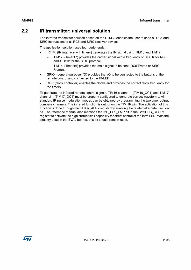
The main program flow is shown in Figure 9.
Figure 9. Main loop flowchart
1. The carrier frequency is specific for each IR protocol (36 kHz for RC5, 40 kHz for SIRC).
2. The envelop signal is specific for each IR protocol (889 µs for RC5, 600 µs for SIRC).
The objective of TIM17 is to generate the carrier signal.
TIM17_Period = (SystemCoreClock / FrequencyCarrier) - 1
TIM16 is used to generate the envelop signal.
TIM16_Period = (SystemCoreClock / FrequencyEnvelop) - 1
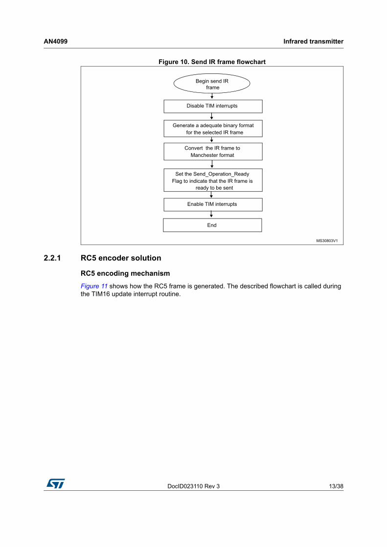
Once the modules are initialized (IRTIM, frame fields), the application waits for the SEL button to be pressed to send the IR data. Figure 10 shows the send frame flowchart.
DocID023110 Rev 3 13/38
AN4099 Infrared transmitter
37
Figure 10. Send IR frame flowchart
2.2.1 RC5 encoder solution
RC5 encoding mechanism
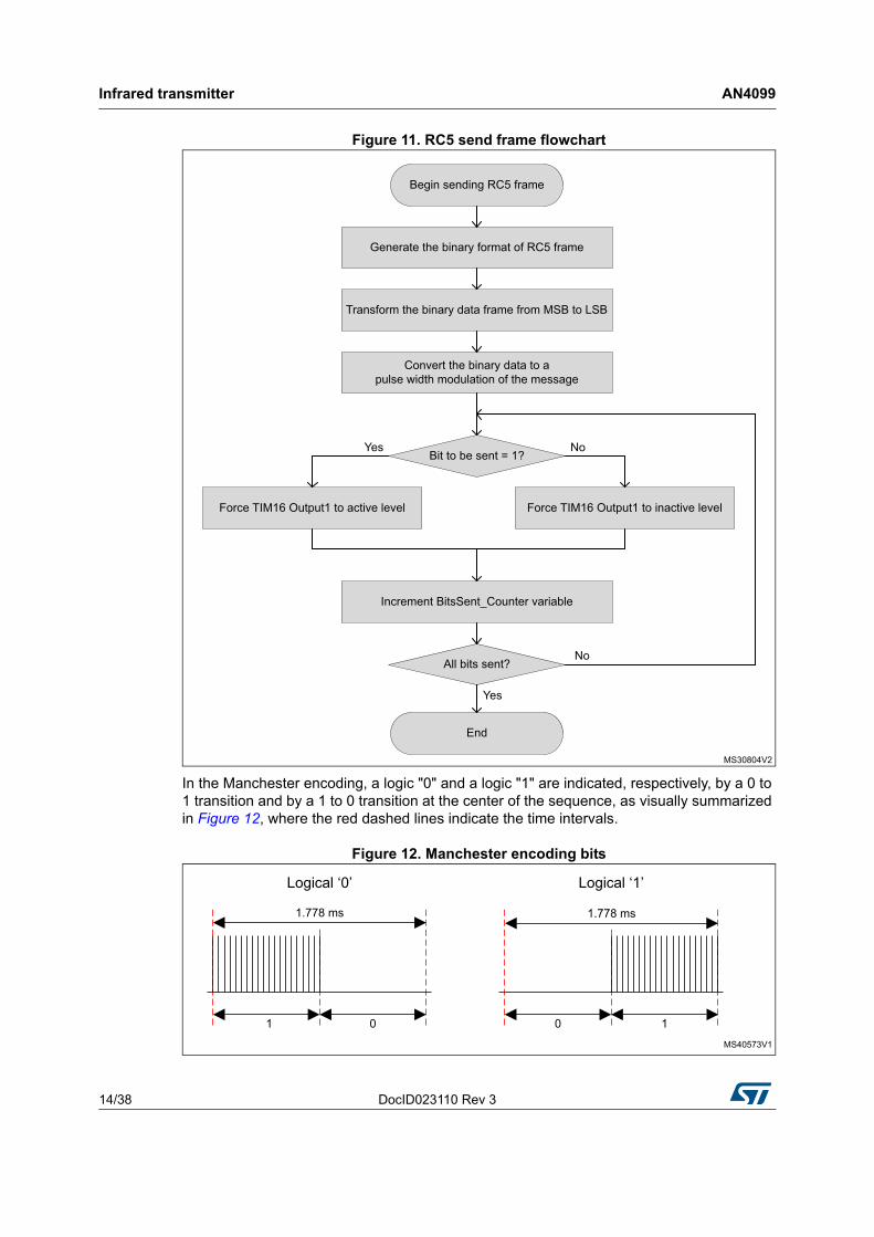
Figure 11 shows how the RC5 frame is generated. The described flowchart is called during the TIM16 update interrupt routine.
Infrared transmitter AN4099
14/38 DocID023110 Rev 3
Figure 11. RC5 send frame flowchart
In the Manchester encoding, a logic "0" and a logic "1" are indicated, respectively, by a 0 to 1 transition and by a 1 to 0 transition at the center of the sequence, as visually summarized in Figure 12, where the red dashed lines indicate the time intervals.
Figure 12. Manchester encoding bits
DocID023110 Rev 3 15/38
AN4099 Infrared transmitter
37
RC5 encoding library
The RC5 encoder driver is based on the following functions.
RC5_Encode_Init()
This function initializes the different peripherals (GPIO, TIMER,...).
RC5_Encode_SendFrame()
This function sends the Manchester format RC5 frame.
RC5_Encode_SignalGenerate()
This function generates the frame signal by monitoring the output level of TIM16. It is called during the TIM16 update interrupt to handle the output signal.
2.2.2 How to use the RC5 encoder driver
To use the RC5 encoder driver, proceed as follows.
– Call the function RC5_Encode_Init() to configure the timer and GPIO hardware resources needed for RC5 encoding.
– Call the function RC5_Encode_SendFrame() to send the RC5 frame.
– TIM16 Update interrupts are used to encode the RC5 frame in pulse width modulation.
Infrared transmitter AN4099
16/38 DocID023110 Rev 3
2.2.3 SIRC encoder solution
SIRC encoding mechanism
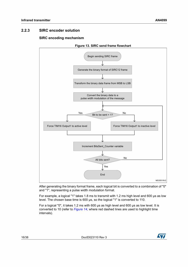
Figure 13. SIRC send frame flowchart
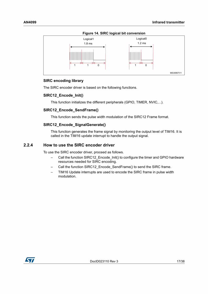
After generating the binary format frame, each logical bit is converted to a combination of "0" and "1", representing a pulse width modulation format.
For example, a logical "1" takes 1.8 ms to transmit with 1.2 ms high level and 600 µs as low level. The chosen base time is 600 µs, so the logical "1" is converted to 110.
For a logical "0", it takes 1.2 ms with 600 µs as high level and 600 µs as low level. It is converted to 10 (refer to Figure 14, where red dashed lines are used to highlight time intervals).
DocID023110 Rev 3 17/38
AN4099 Infrared transmitter
37
Figure 14. SIRC logical bit conversion
SIRC encoding library
The SIRC encoder driver is based on the following functions.
SIRC12_Encode_Init()
This function initializes the different peripherals (GPIO, TIMER, NVIC,...).
SIRC12_Encode_SendFrame()
This function sends the pulse width modulation of the SIRC12 Frame format.
SIRC12_Encode_SignalGenerate()
This function generates the frame signal by monitoring the output level of TIM16. It is called in the TIM16 update interrupt to handle the output signal.
2.2.4 How to use the SIRC encoder driver
To use the SIRC encoder driver, proceed as follows.
– Call the function SIRC12_Encode_Init() to configure the timer and GPIO hardware resources needed for SIRC encoding.
– Call the function SIRC12_Encode_SendFrame() to send the SIRC frame.
– TIM16 Update interrupts are used to encode the SIRC frame in pulse width modulation.
Infrared receiver AN4099
18/38 DocID023110 Rev 3
3 Infrared receiver
3.1 Hardware considerations
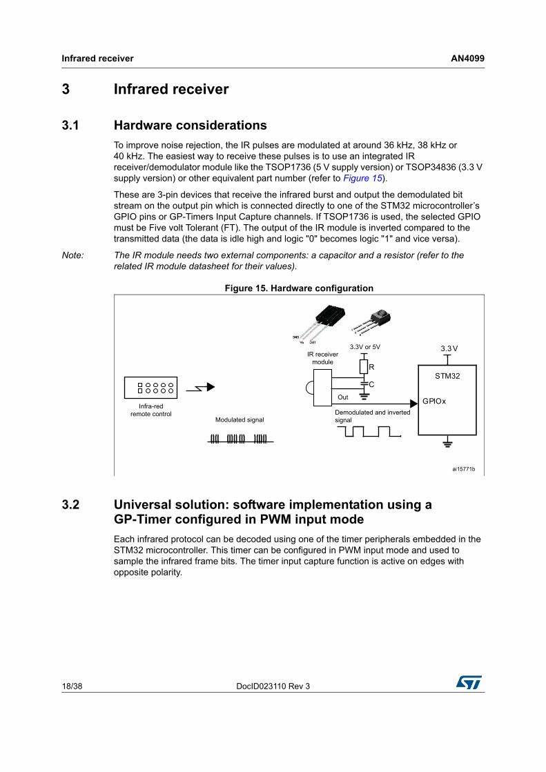
To improve noise rejection, the IR pulses are modulated at around 36 kHz, 38 kHz or 40 kHz. The easiest way to receive these pulses is to use an integrated IR receiver/demodulator module like the TSOP1736 (5 V supply version) or TSOP34836 (3.3 V supply version) or other equivalent part number (refer to Figure 15).
These are 3-pin devices that receive the infrared burst and output the demodulated bit stream on the output pin which is connected directly to one of the STM32 microcontroller’s GPIO pins or GP-Timers Input Capture channels. If TSOP1736 is used, the selected GPIO must be Five volt Tolerant (FT). The output of the IR module is inverted compared to the transmitted data (the data is idle high and logic "0" becomes logic "1" and vice versa).
Note: The IR module needs two external components: a capacitor and a resistor (refer to the related IR module datasheet for their values).
Figure 15. Hardware configuration
3.2 Universal solution: software implementation using a GP-Timer configured in PWM input mode
Each infrared protocol can be decoded using one of the timer peripherals embedded in the STM32 microcontroller. This timer can be configured in PWM input mode and used to sample the infrared frame bits. The timer input capture function is active on edges with opposite polarity.
DocID023110 Rev 3 19/38
AN4099 Infrared receiver
37
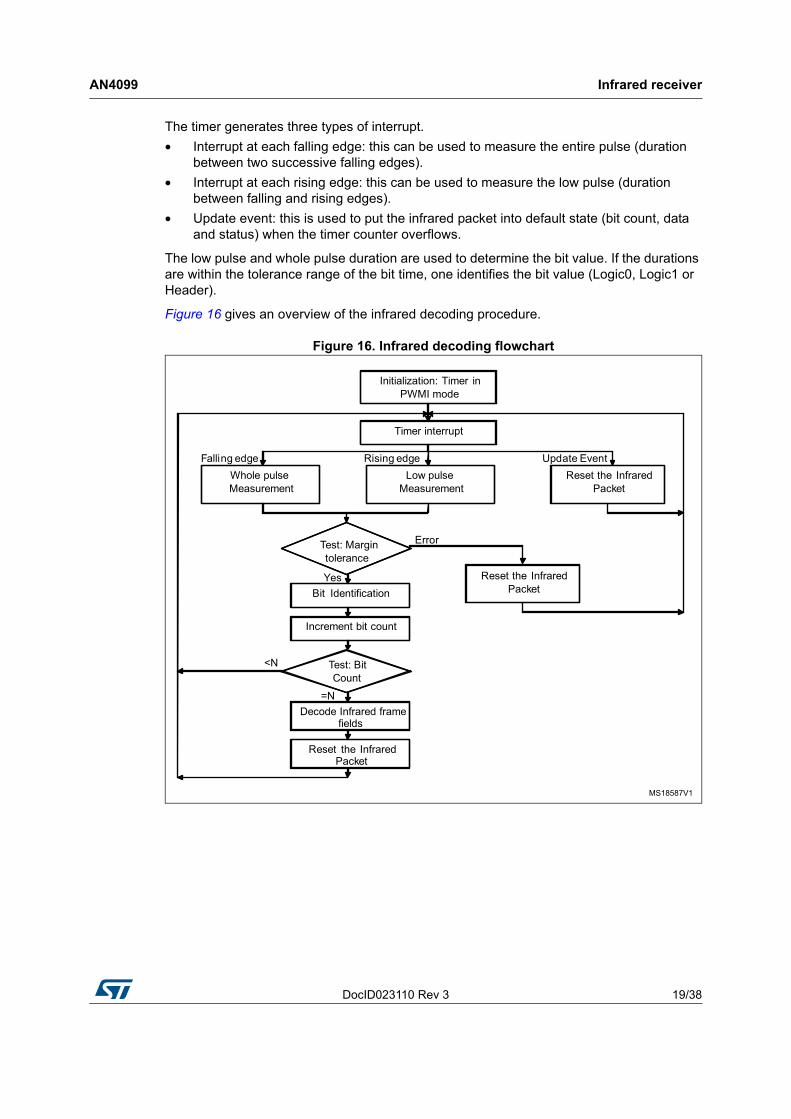
The timer generates three types of interrupt.
• Interrupt at each falling edge: this can be used to measure the entire pulse (duration between two successive falling edges).
• Interrupt at each rising edge: this can be used to measure the low pulse (duration between falling and rising edges).
• Update event: this is used to put the infrared packet into default state (bit count, data and status) when the timer counter overflows.
The low pulse and whole pulse duration are used to determine the bit value. If the durations are within the tolerance range of the bit time, one identifies the bit value (Logic0, Logic1 or Header).
Figure 16 gives an overview of the infrared decoding procedure.
Figure 16. Infrared decoding flowchart
Infrared receiver AN4099
20/38 DocID023110 Rev 3
3.3 RC5 protocol solutions
3.3.1 RC5 frame decoding mechanism
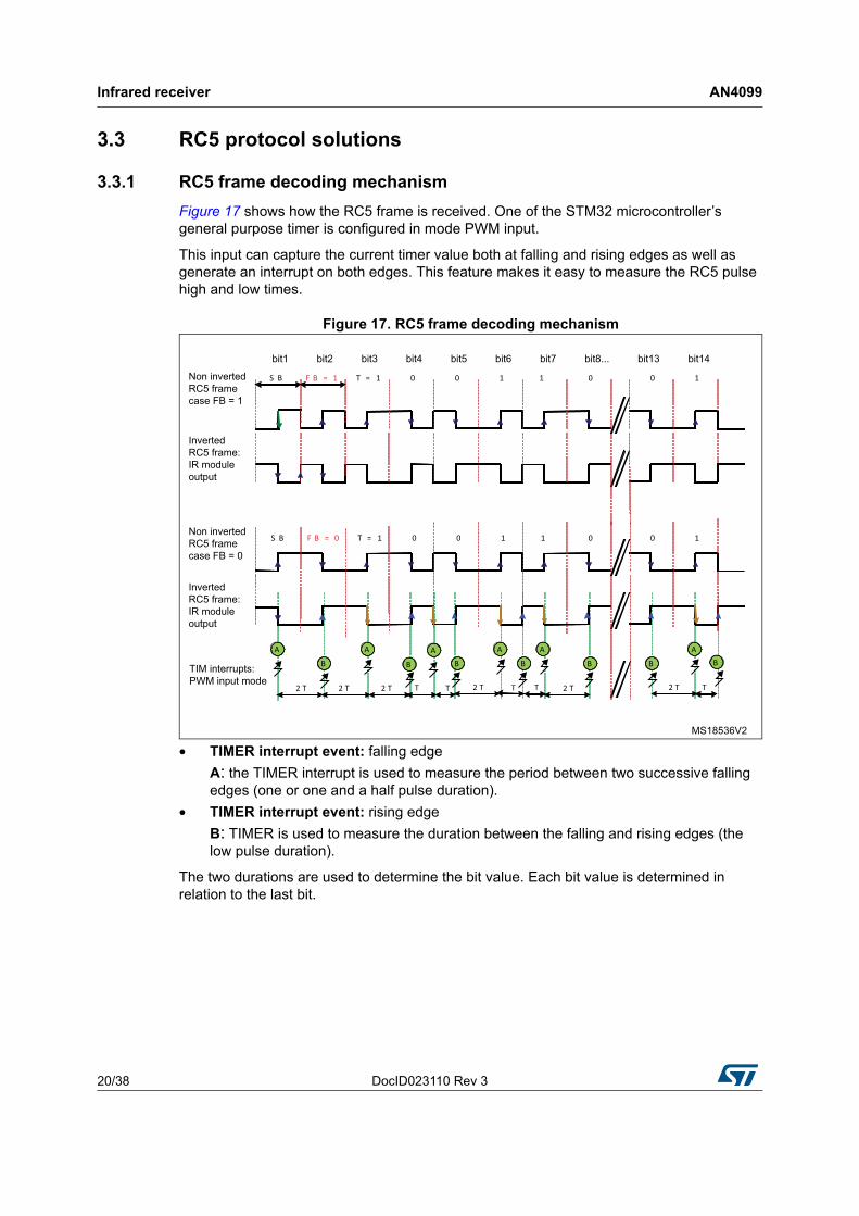
Figure 17 shows how the RC5 frame is received. One of the STM32 microcontroller’s general purpose timer is configured in mode PWM input.
This input can capture the current timer value both at falling and rising edges as well as generate an interrupt on both edges. This feature makes it easy to measure the RC5 pulse high and low times.
Figure 17. RC5 frame decoding mechanism
• TIMER interrupt event: falling edge
A: the TIMER interrupt is used to measure the period between two successive falling edges (one or one and a half pulse duration).
• TIMER interrupt event: rising edge
B: TIMER is used to measure the duration between the falling and rising edges (the low pulse duration).
The two durations are used to determine the bit value. Each bit value is determined in relation to the last bit.
DocID023110 Rev 3 21/38
AN4099 Infrared receiver
37
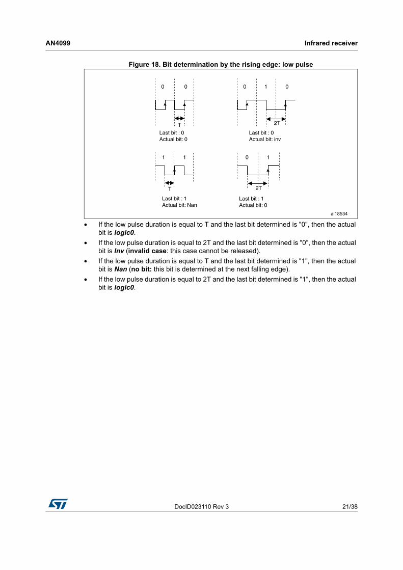
Figure 18. Bit determination by the rising edge: low pulse
• If the low pulse duration is equal to T and the last bit determined is "0", then the actual bit is logic0.
• If the low pulse duration is equal to 2T and the last bit determined is "0", then the actual bit is Inv (invalid case: this case cannot be released).
• If the low pulse duration is equal to T and the last bit determined is "1", then the actual bit is Nan (no bit: this bit is determined at the next falling edge).
• If the low pulse duration is equal to 2T and the last bit determined is "1", then the actual bit is logic0.
Infrared receiver AN4099
22/38 DocID023110 Rev 3
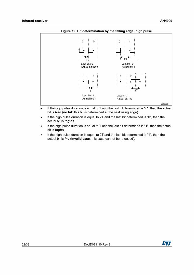
Figure 19. Bit determination by the falling edge: high pulse
• If the high pulse duration is equal to T and the last bit determined is "0", then the actual bit is Nan (no bit: this bit is determined at the next rising edge).
• If the high pulse duration is equal to 2T and the last bit determined is "0", then the actual bit is logic1.
• If the high pulse duration is equal to T and the last bit determined is "1", then the actual bit is logic1.
• If the high pulse duration is equal to 2T and the last bit determined is "1", then the actual bit is Inv (invalid case: this case cannot be released).
DocID023110 Rev 3 23/38
AN4099 Infrared receiver
37
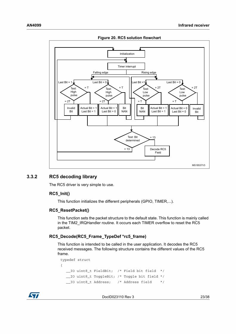
Figure 20. RC5 solution flowchart
3.3.2 RC5 decoding library
The RC5 driver is very simple to use.
RC5_Init()
This function initializes the different peripherals (GPIO, TIMER,...).
RC5_ResetPacket()
This function sets the packet structure to the default state. This function is mainly called in the TIM2_IRQHandler routine. It occurs each TIMER overflow to reset the RC5 packet.
RC5_Decode(RC5_Frame_TypeDef *rc5_frame)
This function is intended to be called in the user application. It decodes the RC5 received messages. The following structure contains the different values of the RC5 frame.
typedef struct
{
__IO uint8_t FieldBit; /* Field bit field */
__IO uint8_t ToggleBit; /* Toggle bit field */
__IO uint8_t Address; /* Address field */
Infrared receiver AN4099
24/38 DocID023110 Rev 3
__IO uint8_t Command; /* Command field */
} RC5_Frame_TypeDef ;
IR_RC5_decode () is executed when the RC5FrameReceived flag is equal to YES.
RC5_DeInit()
This function de-initializes the different peripherals (GPIO, TIMER...).
TIM2_IRQHandler ()
This function handles the TIM Capture Compare interrupt.
– Timer Falling Edge Event: this is used to measure the period between two successive falling edges (the entire pulse duration).
– Timer Rising Edge Event: this is used to measure the duration between falling and rising edges (the low pulse duration).
– Update event (time-out event): this resets the RC5 packet. The Timer Overflow is set to 3.7 ms.
The low pulse duration and the whole pulse duration are used to determine the bit value. Each bit value is determined in relation to the last bit.
3.3.3 How to use the RC5 decoder driver
To use the RC5 decoder driver, proceed as follows.
– Call the function RC5_Init() to configure the timer and GPIO hardware resources needed for RC5 decoding.
– TIM2 Capture Compare and Update interrupts are used to decode the RC5 frame, if a frame is received correctly a global variable "RC5FrameReceived" is set to inform the application.
– The application should then call the function RC5_Decode() to retrieve the received RC5 frame.
Code example
#include "rc5_decode.h"
/* IR_FRAME will hold the RC5 frame (Address, Command,...) */
RC5_Frame_TypeDef IR_FRAME;
/* Initialize the RC5 driver */
RC5_Init();
while(1)
{
/* Decode the received RC5 frame and store it in IR_FRAME variable */
RC5_Decode(&IR_FRAME);
/* Here add the code that will process the just received frame, i.e. IR_FRAME variable, otherwise it will be overwritten by the next frame */
DocID023110 Rev 3 25/38
AN4099 Infrared receiver
37
...
}
Note: 1 TIMx_IRQHandler ISRs are coded within the stm32f0xx_it.c or stm32f3xx_it.c
• If one or both interrupts are used in the application special care must be taken:
– either add the application code in these ISRs, or
– copy the contents of these ISRs in the application code.
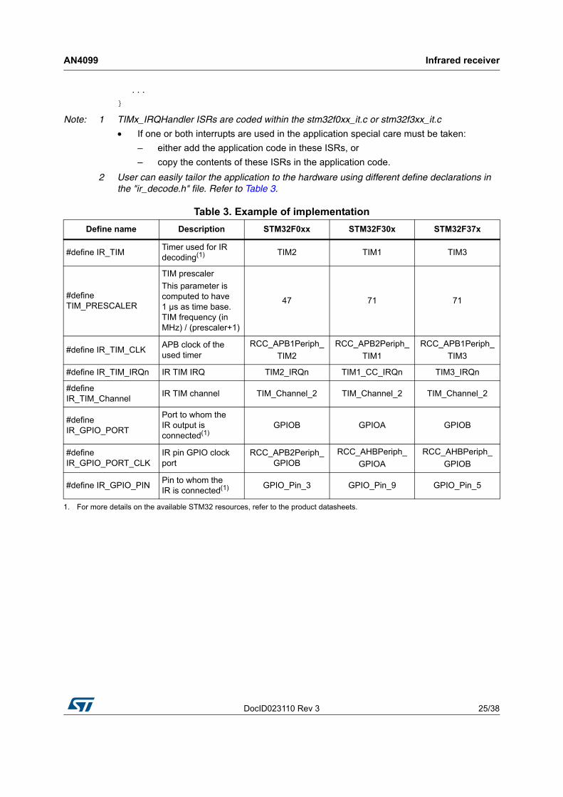
2 User can easily tailor the application to the hardware using different define declarations in the "ir_decode.h" file. Refer to Table 3.
Table 3. Example of implementation
Define name Description STM32F0xx STM32F30x STM32F37x
#define IR_TIMTimer used for IR decoding(1) TIM2 TIM1 TIM3
#define TIM_PRESCALER
TIM prescaler
This parameter is computed to have 1 µs as time base. TIM frequency (in MHz) / (prescaler+1)
47 71 71
#define IR_TIM_CLK APB clock of the used timer
RCC_APB1Periph_
TIM2
RCC_APB2Periph_
TIM1
RCC_APB1Periph_
TIM3
#define IR_TIM_IRQn IR TIM IRQ TIM2_IRQn TIM1_CC_IRQn TIM3_IRQn
#define IR_TIM_Channel
IR TIM channel TIM_Channel_2 TIM_Channel_2 TIM_Channel_2
#define IR_GPIO_PORT
Port to whom the IR output is connected(1)
GPIOB GPIOA GPIOB
#define IR_GPIO_PORT_CLK
IR pin GPIO clock port
RCC_APB2Periph_GPIOB
RCC_AHBPeriph_
GPIOA
RCC_AHBPeriph_
GPIOB
#define IR_GPIO_PIN Pin to whom the IR is connected(1) GPIO_Pin_3 GPIO_Pin_9 GPIO_Pin_5
1. For more details on the available STM32 resources, refer to the product datasheets.
Infrared receiver AN4099
26/38 DocID023110 Rev 3
3.4 SIRC infrared control solution
3.4.1 Software implementation
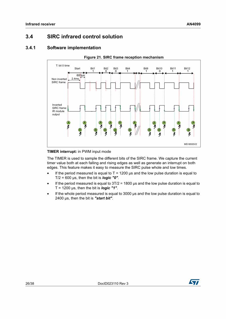
Figure 21. SIRC frame reception mechanism
TIMER interrupt: in PWM input mode
The TIMER is used to sample the different bits of the SIRC frame. We capture the current timer value both at each falling and rising edges as well as generate an interrupt on both edges. This feature makes it easy to measure the SIRC pulse whole and low times.
• If the period measured is equal to T = 1200 µs and the low pulse duration is equal to T/2 = 600 µs, then the bit is logic "0".
• If the period measured is equal to 3T/2 = 1800 µs and the low pulse duration is equal to T = 1200 µs, then the bit is logic "1".
• If the whole period measured is equal to 3000 µs and the low pulse duration is equal to 2400 µs, then the bit is "start bit".
DocID023110 Rev 3 27/38
AN4099 Infrared receiver
37
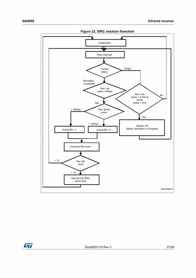
Figure 22. SIRC solution flowchart
Infrared receiver AN4099
28/38 DocID023110 Rev 3
3.4.2 SIRC library
SIRC_Init()
This function initializes the different peripherals used for the SIRC protocol.
SIRC_Decode (SIRC_Frame_TypeDef *sirc_frame)
This function is intended to be called in the user application. It decodes the SIRC received messages. It has as a parameter a structure that contains the different values of the IR frame.
typedef struct
{
__IO uint8_t Command; /* Command field */
__IO uint8_t Address; /* Address field */
} SIRC_Frame_TypeDef;
SIRC_decode () must be executed when the IRFrameReceived flag is equal to YES.
SIRC_ResetPacket()
This function puts the IR packet to the default state. This function is called in the TIM2_IRQHandler routine. It occurs each timer overflow to reset the IR packet.
SIRC_DeInit()
This function de-initializes the different peripherals used for the SIRC protocol.
TIM2_IRQHandler ()
This function handles the TIM Capture Compare interrupt.
– Timer Falling Edge Event: this is used to measure the different periods between two successive falling edges in order to identify the frame bits.
– Timer Rising Edge Event: this is used to measure the duration between falling and rising edges (low pulse duration).
– Update event (time-out event): this resets the RC5 packet. The timer overflow is set to 4 ms.
The bit value is determined from these two durations.
3.4.3 How to use the SIRC decoder driver
To use the SIRC decoder driver, proceed as follows.
– TIM2 Capture Compare and Update interrupts are used to decode the IR frame. If a frame is received correctly a global variable "IRFrameReceived" is set to inform the application.
– The application should then call the function SIRC_Decode() to retrieve the received IR frame.
– The user can easily tailor this driver to any other infrared protocol by simply adapting the defines from sirc_decode.h to the infrared protocol specification (Bit Duration, Header Duration, Marge Tolerance, Number of bits...) and the command and device tables.
DocID023110 Rev 3 29/38
AN4099 Infrared receiver
37
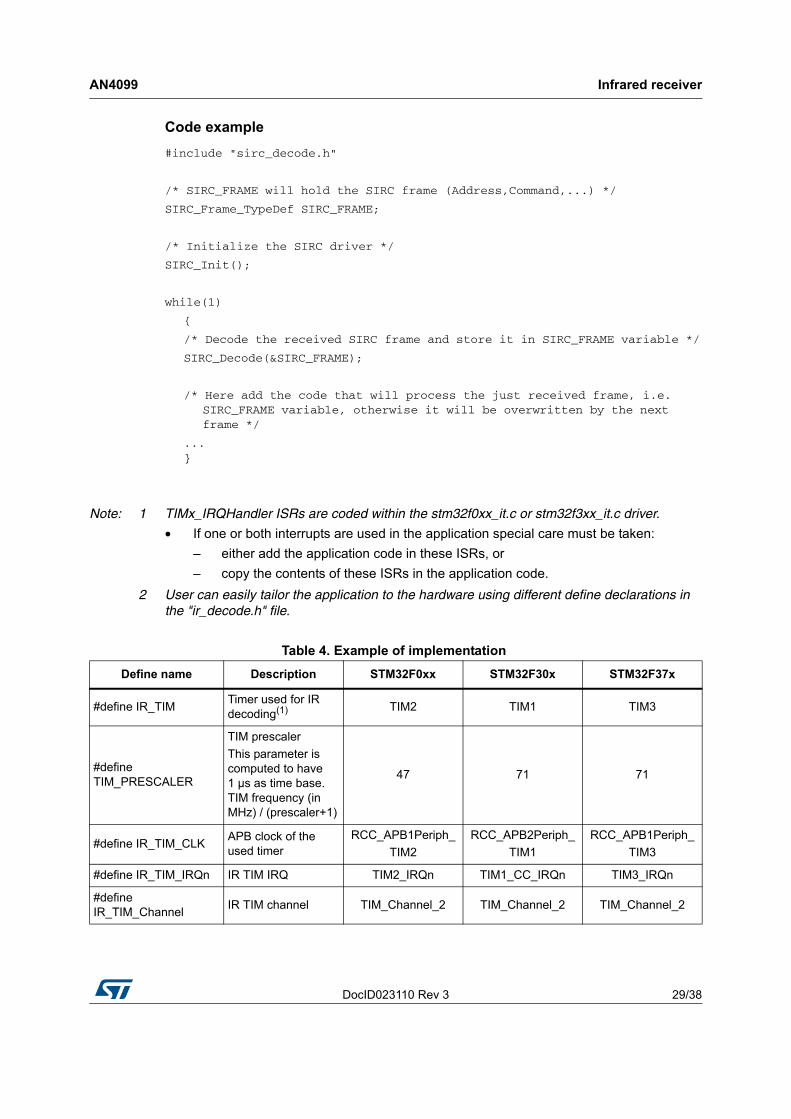
Code example
#include "sirc_decode.h"
/* SIRC_FRAME will hold the SIRC frame (Address,Command,...) */
SIRC_Frame_TypeDef SIRC_FRAME;
/* Initialize the SIRC driver */
SIRC_Init();
while(1)
{
/* Decode the received SIRC frame and store it in SIRC_FRAME variable */
SIRC_Decode(&SIRC_FRAME);
/* Here add the code that will process the just received frame, i.e. SIRC_FRAME variable, otherwise it will be overwritten by the next frame */
... }
Note: 1 TIMx_IRQHandler ISRs are coded within the stm32f0xx_it.c or stm32f3xx_it.c driver.
• If one or both interrupts are used in the application special care must be taken:
– either add the application code in these ISRs, or
– copy the contents of these ISRs in the application code.
2 User can easily tailor the application to the hardware using different define declarations in the "ir_decode.h" file.
Table 4. Example of implementation
Define name Description STM32F0xx STM32F30x STM32F37x
#define IR_TIMTimer used for IR decoding(1) TIM2 TIM1 TIM3
#define TIM_PRESCALER
TIM prescaler
This parameter is computed to have 1 µs as time base. TIM frequency (in MHz) / (prescaler+1)
47 71 71
#define IR_TIM_CLK APB clock of the used timer
RCC_APB1Periph_
TIM2
RCC_APB2Periph_
TIM1
RCC_APB1Periph_
TIM3
#define IR_TIM_IRQn IR TIM IRQ TIM2_IRQn TIM1_CC_IRQn TIM3_IRQn
#define IR_TIM_Channel
IR TIM channel TIM_Channel_2 TIM_Channel_2 TIM_Channel_2
Infrared receiver AN4099
30/38 DocID023110 Rev 3
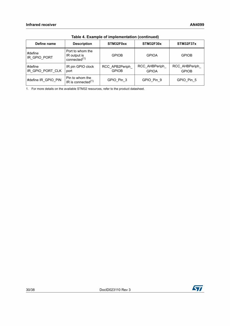
#define IR_GPIO_PORT
Port to whom the IR output is connected(1)
GPIOB GPIOA GPIOB
#define IR_GPIO_PORT_CLK
IR pin GPIO clock port
RCC_APB2Periph_GPIOB
RCC_AHBPeriph_
GPIOA
RCC_AHBPeriph_
GPIOB
#define IR_GPIO_PIN Pin to whom the IR is connected(1) GPIO_Pin_3 GPIO_Pin_9 GPIO_Pin_5
1. For more details on the available STM32 resources, refer to the product datasheet.
Table 4. Example of implementation (continued)
Define name Description STM32F0xx STM32F30x STM32F37x
DocID023110 Rev 3 31/38
AN4099 Interface layer
37
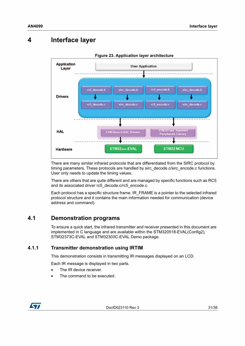
4 Interface layer
Figure 23. Application layer architecture
There are many similar infrared protocols that are differentiated from the SIRC protocol by timing parameters. These protocols are handled by sirc_decode.c/sirc_encode.c functions. User only needs to update the timing values.
There are others that are quite different and are managed by specific functions such as RC5 and its associated driver rc5_decode.c/rc5_encode.c.
Each protocol has a specific structure frame. IR_FRAME is a pointer to the selected infrared protocol structure and it contains the main information needed for communication (device address and command).
4.1 Demonstration programs
To ensure a quick start, the infrared transmitter and receiver presented in this document are implemented in C language and are available within the STM320518-EVAL(Config2), STM32373C-EVAL and STM32303C-EVAL Demo package.
4.1.1 Transmitter demonstration using IRTIM
This demonstration consists in transmitting IR messages displayed on an LCD.
Each IR message is displayed in two parts.
• The IR device receiver.
• The command to be executed.
Interface layer AN4099
32/38 DocID023110 Rev 3
Figure 24. IR transmitter demo
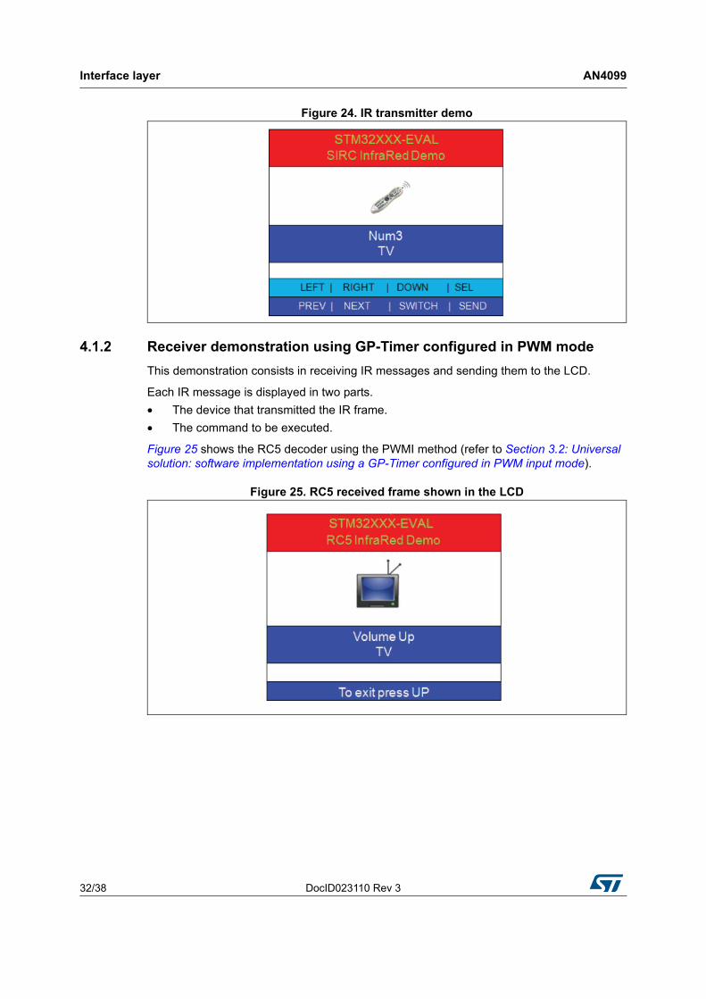
4.1.2 Receiver demonstration using GP-Timer configured in PWM mode
This demonstration consists in receiving IR messages and sending them to the LCD.
Each IR message is displayed in two parts.
• The device that transmitted the IR frame.
• The command to be executed.
Figure 25 shows the RC5 decoder using the PWMI method (refer to Section 3.2: Universal solution: software implementation using a GP-Timer configured in PWM input mode).
Figure 25. RC5 received frame shown in the LCD
DocID023110 Rev 3 33/38
AN4099 Interface layer
37
4.2 How to customize the IR drivers
4.2.1 IR receiver drivers
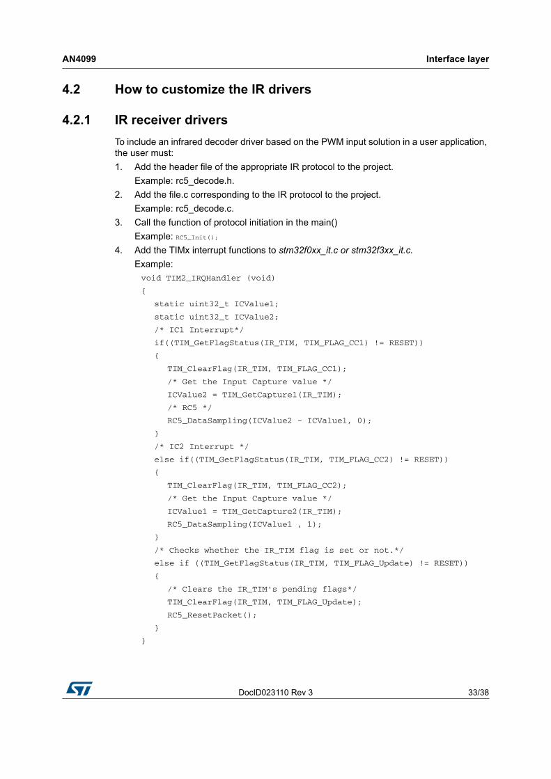
To include an infrared decoder driver based on the PWM input solution in a user application, the user must:
1. Add the header file of the appropriate IR protocol to the project.
Example: rc5_decode.h.
2. Add the file.c corresponding to the IR protocol to the project.
Example: rc5_decode.c.
3. Call the function of protocol initiation in the main()
Example: RC5_Init();
4. Add the TIMx interrupt functions to stm32f0xx_it.c or stm32f3xx_it.c.
Example:
void TIM2_IRQHandler (void)
{
static uint32_t ICValue1;
static uint32_t ICValue2;
/* IC1 Interrupt*/
if((TIM_GetFlagStatus(IR_TIM, TIM_FLAG_CC1) != RESET))
{
TIM_ClearFlag(IR_TIM, TIM_FLAG_CC1);
/* Get the Input Capture value */
ICValue2 = TIM_GetCapture1(IR_TIM);
/* RC5 */
RC5_DataSampling(ICValue2 - ICValue1, 0);
}
/* IC2 Interrupt */
else if((TIM_GetFlagStatus(IR_TIM, TIM_FLAG_CC2) != RESET))
{
TIM_ClearFlag(IR_TIM, TIM_FLAG_CC2);
/* Get the Input Capture value */
ICValue1 = TIM_GetCapture2(IR_TIM);
RC5_DataSampling(ICValue1 , 1);
}
/* Checks whether the IR_TIM flag is set or not.*/
else if ((TIM_GetFlagStatus(IR_TIM, TIM_FLAG_Update) != RESET))
{
/* Clears the IR_TIM's pending flags*/
TIM_ClearFlag(IR_TIM, TIM_FLAG_Update);
RC5_ResetPacket();
}
}
Interface layer AN4099
34/38 DocID023110 Rev 3
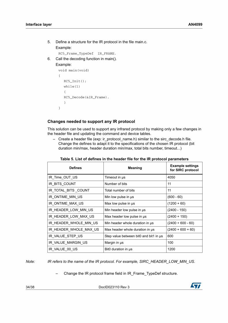
5. Define a structure for the IR protocol in the file main.c.
Example:
RC5_Frame_TypeDef IR_FRAME.
6. Call the decoding function in main().
Example:
void main(void)
{
RC5_Init();
while(1)
{
RC5_Decode(&IR_Frame).
}
}
Changes needed to support any IR protocol
This solution can be used to support any infrared protocol by making only a few changes in the header file and updating the command and device tables.
– Create a header file (exp: ir_protocol_name.h) similar to the sirc_decode.h file. Change the defines to adapt it to the specifications of the chosen IR protocol (bit duration min/max, header duration min/max, total bits number, timeout...)
Note: IR refers to the name of the IR protocol. For example, SIRC_HEADER_LOW_MIN_US.
– Change the IR protocol frame field in IR_Frame_TypeDef structure.
Table 5. List of defines in the header file for the IR protocol parameters
Defines MeaningExample settingsfor SIRC protocol
IR_Time_OUT_US Timeout in µs 4050
IR_BITS_COUNT Number of bits 11
IR_TOTAL_BITS _COUNT Total number of bits 11
IR_ONTIME_MIN_US Min low pulse in µs (600 - 60)
IR_ONTIME_MAX_US Max low pulse in µs (1200 + 60)
IR_HEADER_LOW_MIN_US Min header low pulse in µs (2400 - 150)
IR_HEADER_LOW_MAX_US Max header low pulse in µs (2400 + 150)
IR_HEADER_WHOLE_MIN_US Min header whole duration in µs (2400 + 600 - 60)
IR_HEADER_WHOLE_MAX_US Max header whole duration in µs (2400 + 600 + 60)
IR_VALUE_STEP_US Step value between bit0 and bit1 in µs 600
IR_VALUE_MARGIN_US Margin in µs 100
IR_VALUE_00_US Bit0 duration in µs 1200
DocID023110 Rev 3 35/38
AN4099 Interface layer
37
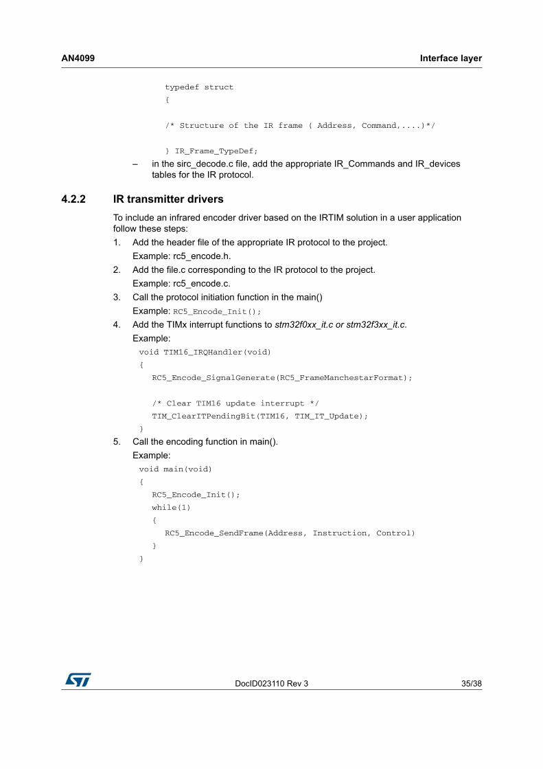
typedef struct
{
/* Structure of the IR frame ( Address, Command,....)*/
} IR_Frame_TypeDef;
– in the sirc_decode.c file, add the appropriate IR_Commands and IR_devices tables for the IR protocol.
4.2.2 IR transmitter drivers
To include an infrared encoder driver based on the IRTIM solution in a user application follow these steps:
1. Add the header file of the appropriate IR protocol to the project.
Example: rc5_encode.h.
2. Add the file.c corresponding to the IR protocol to the project.
Example: rc5_encode.c.
3. Call the protocol initiation function in the main()
Example: RC5_Encode_Init();
4. Add the TIMx interrupt functions to stm32f0xx_it.c or stm32f3xx_it.c.
Example:
void TIM16_IRQHandler(void)
{
RC5_Encode_SignalGenerate(RC5_FrameManchestarFormat);
/* Clear TIM16 update interrupt */
TIM_ClearITPendingBit(TIM16, TIM_IT_Update);
}
5. Call the encoding function in main().
Example:
void main(void)
{
RC5_Encode_Init();
while(1)
{
RC5_Encode_SendFrame(Address, Instruction, Control)
}
}
Conclusion AN4099
36/38 DocID023110 Rev 3
5 Conclusion
This application note provides a solution for implementing an IR transmitter/receiver in software using one of the general-purpose timers available in STM32 microcontrollers.
The IR encoding application uses the STM32F0xx and STM32F3xx microcontrollers and takes advantage of a powerful hardware modulator called IRTIM, that combines signals from two internal timers to drive the IR interface. This feature makes the microcontroller well suited for applications that require IR signal generation capability.
The IR decoding application allows the IR solution to be integrated in the HDMI-CEC module in order to support high-level control functions for all of the various audiovisual products in a given environment.
DocID023110 Rev 3 37/38
AN4099 Revision history
37
6 Revision history
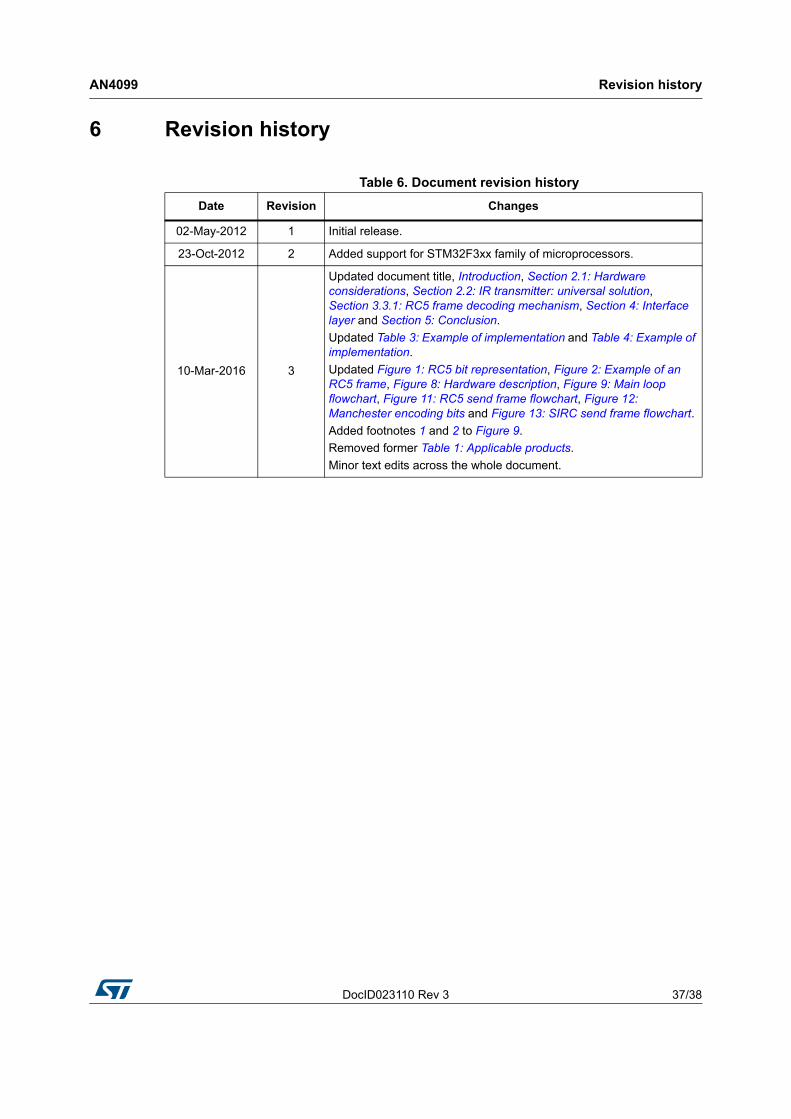
Table 6. Document revision history
Date Revision Changes
02-May-2012 1 Initial release.
23-Oct-2012 2 Added support for STM32F3xx family of microprocessors.
10-Mar-2016 3
Updated document title, Introduction, Section 2.1: Hardware considerations, Section 2.2: IR transmitter: universal solution, Section 3.3.1: RC5 frame decoding mechanism, Section 4: Interface layer and Section 5: Conclusion.
Updated Table 3: Example of implementation and Table 4: Example of implementation.
Updated Figure 1: RC5 bit representation, Figure 2: Example of an RC5 frame, Figure 8: Hardware description, Figure 9: Main loop flowchart, Figure 11: RC5 send frame flowchart, Figure 12: Manchester encoding bits and Figure 13: SIRC send frame flowchart.
Added footnotes 1 and 2 to Figure 9.
Removed former Table 1: Applicable products.
Minor text edits across the whole document.
AN4099
38/38 DocID023110 Rev 3
IMPORTANT NOTICE – PLEASE READ CAREFULLY
STMicroelectronics NV and its subsidiaries (“ST”) reserve the right to make changes, corrections, enhancements, modifications, and improvements to ST products and/or to this document at any time without notice. Purchasers should obtain the latest relevant information on ST products before placing orders. ST products are sold pursuant to ST’s terms and conditions of sale in place at the time of order acknowledgement.
Purchasers are solely responsible for the choice, selection, and use of ST products and ST assumes no liability for application assistance or the design of Purchasers’ products.
No license, express or implied, to any intellectual property right is granted by ST herein.
Resale of ST products with provisions different from the information set forth herein shall void any warranty granted by ST for such product.
ST and the ST logo are trademarks of ST. All other product or service names are the property of their respective owners.
Information in this document supersedes and replaces information previously supplied in any prior versions of this document.
© 2016 STMicroelectronics – All rights reserved