Embed Size (px)
Citation preview
AN5116-06B
Optical Line Terminal Equipment
Product Description
Version: A/1
Code: MN000002128
FiberHome Telecommunication Technologies Co., Ltd.
November 2014


Thank you for choosing our products.
We appreciate your business. Your satisfaction is our goal.
We will provide you with comprehensive technical support
and after-sales service. Please contact your local sales
representative, service representative or distributor for any
help needed at the contact information shown below.
Fiberhome Telecommunication Technologies Co., Ltd.
Address: No. 67, Guanggu Chuangye Jie, Wuhan, Hubei, China
Zip code: 430073
Tel: +6 03 7960 0860/0884 (for Malaysia)
+91 98 9985 5448 (for South Asia)
+593 4 501 4529 (for South America)
Fax: +86 27 8717 8521
Website: http://www.fiberhomegroup.com


Legal Notice
are trademarks of FiberHome Telecommunication Technologies Co., Ltd.
(Hereinafter referred to as FiberHome)
All brand names and product names used in this document are used for
identification purposes only and are trademarks or registered trademarks
of their respective holders.
All rights reserved
No part of this document (including the electronic version) may be
reproduced or transmitted in any form or by any means without prior
written permission from FiberHome.
Information in this document is subject to change without notice.

Preface
Related Documentation
Document Description
AN5116-06B Optical Line
Terminal Equipment Product
Description
Introduces functional features, application model, network
management system and technical specifications of
AN5116-06B. It aims to acquaint users with the equipment,
its performance and technology applied, and provide users
with technical support.
AN5116-06B Optical Line
Terminal Equipment Hardware
Description
Introduces the appearance, structure, functions, technical
specifications, and operating method for the AN5116-06B’s
cabinet, PDP, subrack, cards, cables and wires, facilitating
users’ mastery of the hardware features of the equipment.
AN5116-06B Optical Line
Terminal Equipment Installation
Guide
Introduces the overall installation and acceptance
inspection procedures from unpacking inspection to power-
on examination after the AN5116-06B is delivered on site,
and provides reference information (e.g. safety principles
and wiring scheme of various interfaces) to guide users to
install the equipment.
AN5116-06B Optical Line
Terminal Equipment Quick
Installation Guide
Mainly use diagrams to introduce the installation of the
AN5116-06B components such as cabinet, subrack and so
on, and the connection and layout of cables and wires,
aiming to guide the hardware installation engineer to install
the equipment in a quick and normative way.
AN5116-06B Optical Line
Terminal Equipment EPON
Configuration Guide
Introduces the method for configuring the EPON services
supported by the AN5116-06B via the UNM2000, such as
basic configuration, voice service configuration, data
service configuration, multicast service configuration, and
software upgrading configuration, to guide users on start-
up for various services and software upgrading.
AN5116-06B Optical Line
Terminal Equipment GPON
Configuration Guide
Introduces the method for configuring the GPON services
supported by the AN5116-06B via the UNM2000, such as
basic configuration, voice service configuration, data
service configuration, multicast service configuration, and
software upgrading configuration, to guide users on start-
up for various services and software upgrading.
I

Version
Version Description
A
This manual corresponds to the AN5116-06B of Version 4.
0.
Initial version.
Intended Readers
This manual is intended for the following readers:
u Marketing personnel
u Commissioning engineers
u Operation and maintenance engineers
To utilize this manual, these prerequisite skills are necessary:
u EPON technology
u 10G EPON technology
u GPON technology
u Multicast technology
u NGN voice technology
u Ethernet switch technology
u Computer network technology
II

Conventions
Terminology Conventions
Terminology Convention
AN5116-06B AN5116-06B Optical Line Terminal Equipment
UNM2000FiberHome UNM2000 Network Convergence Management
System
EC4B 4×EPON-C Interface Card (Type B)
EC8B 8×EPON-C Interface Card (Type B)
ECOB 16*EPON Interface Card (Type B)
GC4B 4×GPON-B Interface Card (Type B)
GC8B 8×GPON_C Interface Card (Type B)
GCOB 16 Port GPON OLT Line Card (Type B)
XG8A 8×10G EPON Service Card
C155A 1×STM-1 Optical Interface Card (CES Mode)
CE1B 32×E1 Interface Card (Type B)
TIMA Time Board
HSWA Core Switch Card (Type A)
HSWD Core Switch Card (Type D)
HU1A 4×GE + 1×10GE Uplink Card
HU1BUplink Five Port Board (4×GE+1×10GE, supporting
synchronous Ethernet)
HU2A 2×GE +2×10GE Optical Interface Uplink Card
GU6F 6×GE Optical Interface Uplink Card
GU6BGPON Uplink Board (6×GE, supporting synchronous
Ethernet)
GSOF 16×GE Interface Card
Symbol Conventions
Symbol Meaning Description
Note Important features or operation guide.
CautionPossible injury to persons or systems, or cause traffic
interruption or loss.
III
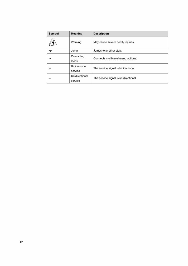
Symbol Meaning Description
Warning May cause severe bodily injuries.
➔ Jump Jumps to another step.
→Cascading
menuConnects multi-level menu options.
↔Bidirectional
serviceThe service signal is bidirectional.
→Unidirectional
serviceThe service signal is unidirectional.
IV

Contents
Preface...................................................................................................................I
Related Documentation ...................................................................................I
Version ...........................................................................................................II
Intended Readers ...........................................................................................II
Conventions ..................................................................................................III
1 Product Introduction.....................................................................................1-1
1.1 Product Positioning........................................................................1-2
1.2 Functions and Features .................................................................1-3
1.2.1 EPON / GPON / 10G EPON Integrated Access Capability 1-3
1.2.2 Interface Type..................................................................1-6
1.2.3 Support to IPv6 Protocol ..................................................1-7
1.2.4 Multicast Function............................................................1-9
1.2.5 Voice Function...............................................................1-11
1.2.6 Layer 3 Routing Function ...............................................1-12
1.2.7 VLAN Function ..............................................................1-13
1.2.8 QoS Guarantee .............................................................1-15
1.2.9 Security Mechanism ......................................................1-17
1.2.10 Reliability Design ...........................................................1-19
1.2.11 Maintainability and Manageability...................................1-21
1.3 List of Functions and Features .....................................................1-23
2 Product Application......................................................................................2-1
2.1 Network Introduction ......................................................................2-2
2.2 Network Application .......................................................................2-2
2.2.1 Triple Play Application......................................................2-2
2.2.2 MSTP Service Application................................................2-3
2.2.3 TDM Service Application..................................................2-4
2.2.4 Residence and Home Application.....................................2-5
2.2.5 Small Cell Bearing Application .........................................2-7
2.2.6 High Bandwidth Access Application .................................2-8
2.2.7 Wi-Fi Hot Spot Covering Application...............................2-10
3 Product Composition....................................................................................3-1
3.1 Logical Architecture .......................................................................3-2
3.2 Hardware Structure........................................................................3-3
3.2.1 19-inch Cabinet ...............................................................3-3
3.2.2 21-inch Cabinet (without the Anti-dust Screen) .................3-5
3.2.3 21-inch Cabinet (with the Anti-dust Screen) ......................3-8
3.2.4 PDP ..............................................................................3-10
3.2.5 Subrack.........................................................................3-11
3.2.6 Card ..............................................................................3-14
3.3 Software Architecture...................................................................3-15
4 System Management ...................................................................................4-1
4.1 Management Mode........................................................................4-2
4.2 CLI Network Management System .................................................4-3
4.3 The UNM2000 ...............................................................................4-3
4.3.1 Function ..........................................................................4-4
4.3.2 Operating Environment ....................................................4-5
4.3.3 Network Mode .................................................................4-7
5 Technical Specification and Standard ...........................................................5-1
5.1 Performance Parameter.................................................................5-2
5.1.1 Overall Performance........................................................5-2
5.1.2 Access Capability ............................................................5-5
5.1.3 Reliability Specifications ..................................................5-6
5.2 Interface Specifications..................................................................5-7
5.2.1 Specifications of Interfaces on the EC4B / EC8B / ECOB
Card ................................................................................5-7
5.2.2 Specifications of Interface on the XG8A Card ...................5-7
5.2.3 Interface Specifications of the GC4B / GC8B / GCOB
Card ................................................................................5-8
5.2.4 Interface Specifications of the HU1A / HU1B / HU2A Card5-9
5.2.5 Interface Specifications of the HU4A Card......................5-10
5.2.6 Interface Specifications of the GU6F / GU6B / GSOF
Card ..............................................................................5-11
5.2.7 Interface Specifications of the CE1B Card ......................5-12
5.2.8 Interface Specifications of the C155A Card.....................5-12

5.2.9 Interface Specifications of the HSWA Card.....................5-13
5.2.10 Interface Specifications of the HSWD Card.....................5-14
5.2.11 Interface Specifications of the TIMA Card.......................5-14
5.3 Mechanical Dimensions and Weight.............................................5-15
5.4 Power Supply and Power Consumption........................................5-15
5.5 Equipment Room Requirement ....................................................5-16
5.5.1 Power Supply Requirement............................................5-16
5.5.2 Working Environment.....................................................5-16
5.6 Standard and Protocol .................................................................5-16
5.6.1 Environment Standard ...................................................5-17
5.6.2 Electromagnetic Compatibility Standard .........................5-18
5.6.3 Safety Standard.............................................................5-19
5.6.4 10G EPON Standard .....................................................5-20
5.6.5 EPON Standard.............................................................5-20
5.6.6 GPON Standard ............................................................5-21
5.6.7 Ethernet Protocol ...........................................................5-21
5.6.8 Routing Protocol ............................................................5-22
5.6.9 NGN Protocol ................................................................5-22
5.6.10 IMS Protocol..................................................................5-23
5.6.11 TDM Service Standard...................................................5-23
5.6.12 Time Standard ...............................................................5-23
5.6.13 Other Standard and Protocol..........................................5-24
Appendix A Abbreviations .......................................................................... A-1


Figures
Figure 1-1 The AN5116-06B's Position in the Network.....................................1-2
Figure 1-2 Physical Interfaces of the AN5116-06B...........................................1-6
Figure 2-1 Network Diagram of the AN5116-06B .............................................2-2
Figure 2-2 The Triple Play Application of the AN5116-06B...............................2-3
Figure 2-3 Network of the AN5116-06B in MSTP Service ................................2-4
Figure 2-4 Network of the AN5116-06B in TDM Service...................................2-5
Figure 2-5 Application of the AN5116-06B in Residential Districts and
Families.........................................................................................2-6
Figure 2-6 Application of the AN5116-06B in the Small Cell .............................2-7
Figure 2-7 Application of the AN5116-06B in High Bandwidth Access..............2-9
Figure 2-8 Application of the AN5116-06B in the Wi-Fi Hot Spot Covering .....2-11
Figure 3-1 Logical Architecture of the AN5116-06B .........................................3-2
Figure 3-2 Appearance of a 19-inch Cabinet ...................................................3-4
Figure 3-3 Typical Layout of a 19-inch Cabinet ................................................3-5
Figure 3-4 Appearance of a 21-inch Cabinet (without the Anti-dust Screen) .....3-6
Figure 3-5 Typical Layout of a 21-inch Cabinet (without the Anti-dust Screen)..3-7
Figure 3-6 Appearance of a 21-inch Cabinet (with the Anti-dust Screen)..........3-8
Figure 3-7 Typical Layout of a 21-inch Cabinet (with the Anti-dust Screen) ......3-9
Figure 3-8 Appearance of the PDP ...............................................................3-11
Figure 3-9 Subrack Structure ........................................................................3-12
Figure 3-10 Subrack Slot Allocation and Typical Configuration ........................3-13
Figure 3-11 Software Architecture of the AN5116-06B System ........................3-16
Figure 4-1 Network Diagram for the CLI Network Management System...........4-3
Figure 4-2 Network Example ..........................................................................4-8


Tables
Table 1-1 Interfaces of the AN5116–06B........................................................1-6
Table 1-2 List of Functions and Features .....................................................1-23
Table 3-1 Description of Subrack Structure ..................................................3-12
Table 3-2 Card Function List........................................................................3-14
Table 4-1 Hardware Configuration Requirement for the Server End................4-5
Table 4-2 Software Configuration Requirements for the Server End ...............4-6
Table 4-3 Hardware Configuration Requirement for the Client End .................4-6
Table 4-4 Software Configuration Requirement for the Client End ..................4-7
Table 5-1 The Overall Performance of the Equipment ....................................5-2
Table 5-2 The DBA Performance of the Equipment ........................................5-2
Table 5-3 The Ethernet Service Performance of the Equipment......................5-2
Table 5-4 The Voice Service Performance of the Equipment ..........................5-4
Table 5-5 The TDM Service Performance of the Equipment ...........................5-4
Table 5-6 The Access Capability of the Equipment.........................................5-5
Table 5-7 The Card Reliability Specifications .................................................5-6
Table 5-8 The Equipment Reliability Specifications ........................................5-6
Table 5-9 Specifications of Interfaces on the EC4B / EC8B / ECOB Card .......5-7
Table 5-10 Specifications of Interface on the XG8A Card .................................5-7
Table 5-11 Interface Specifications of the GC4B / GC8B / GCOB Card (Class B
+) ..................................................................................................5-8
Table 5-12 Interfaces Specifications of the GC4B / GC8B / GCOB Card (Class C
+) ..................................................................................................5-9
Table 5-13 Specifications of 10GE Optical Interfaces on the the HU1A / HU1B /
HU2A Card ....................................................................................5-9
Table 5-14 Specifications of GE Optical Interfaces on the the HU1A / HU1B /
HU2A Card ..................................................................................5-10
Table 5-15 Specifications of Ethernet Electrical Interfaces on the the HU1A /
HU1B / HU2A Card ......................................................................5-10
Table 5-16 Ethernet Optical Interface Specifications of the HU4A Card ..........5-10
Table 5-17 Specifications of Ethernet Optical Interfaces on the GU6F / GU6B /
GSOF Card .................................................................................5-11
Table 5-18 Specifications of Ethernet Electrical Interfaces on the GU6F / GU6B /
GSOF Card .................................................................................5-11
Table 5-19 Interface Specifications of the CE1B Card ....................................5-12
Table 5-20 Interface Specifications of the C155A Card...................................5-12
Table 5-21 Interface Specifications of the HSWA Card...................................5-13
Table 5-22 Interface Specifications of the HSWD Card...................................5-14
Table 5-23 Electrical Interface Specifications of the TIMA Card ......................5-14
Table 5-24 Optical Interface Specifications of the TIMA Card .........................5-14
Table 5-25 Mechanical Dimensions and Weight of the Equipment..................5-15
Table 5-26 Power Consumption of the Equipment's Cards .............................5-15

1 Product Introduction
The following introduces the applications, functions and features of the AN5116-06B.
Product Positioning
Functions and Features
List of Functions and Features
Version: A/1 1-1
AN5116-06B Optical Line Terminal Equipment Product Description
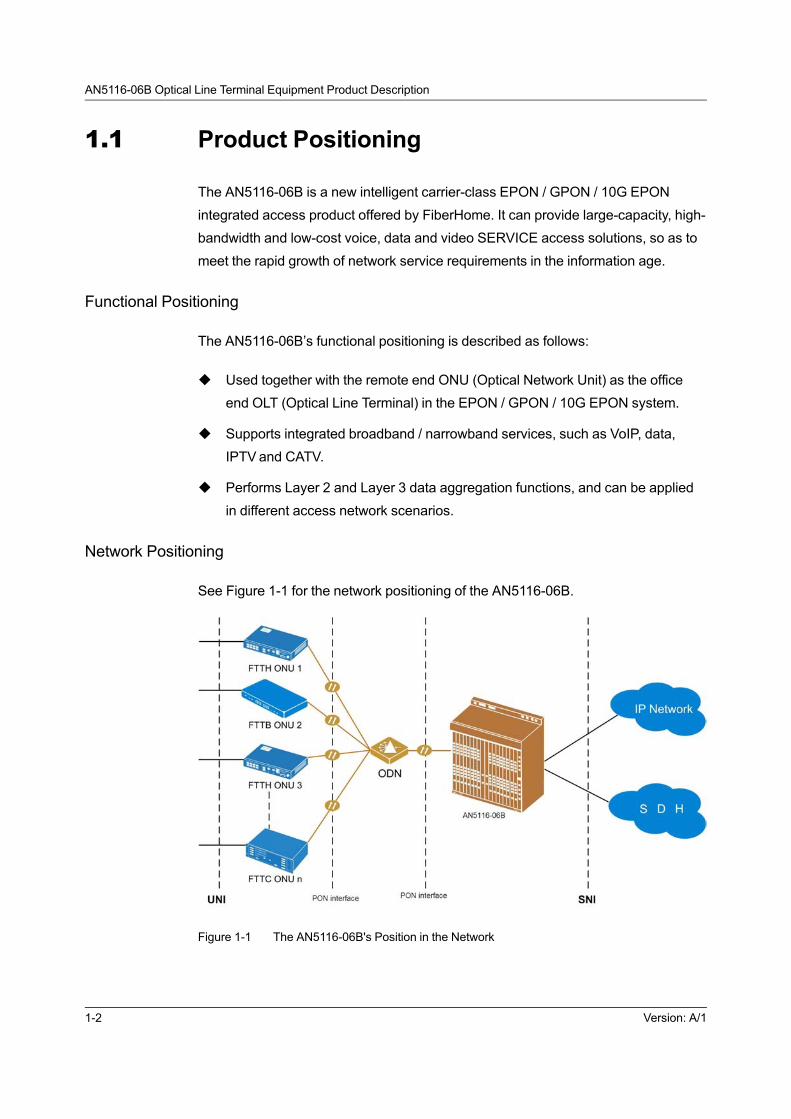
1.1 Product Positioning
The AN5116-06B is a new intelligent carrier-class EPON / GPON / 10G EPON
integrated access product offered by FiberHome. It can provide large-capacity, high-
bandwidth and low-cost voice, data and video SERVICE access solutions, so as to
meet the rapid growth of network service requirements in the information age.
Functional Positioning
The AN5116-06B’s functional positioning is described as follows:
u Used together with the remote end ONU (Optical Network Unit) as the office
end OLT (Optical Line Terminal) in the EPON / GPON / 10G EPON system.
u Supports integrated broadband / narrowband services, such as VoIP, data,
IPTV and CATV.
u Performs Layer 2 and Layer 3 data aggregation functions, and can be applied
in different access network scenarios.
Network Positioning
See Figure 1-1 for the network positioning of the AN5116-06B.
Figure 1-1 The AN5116-06B's Position in the Network
1-2 Version: A/1

1 Product Introduction
The AN5116-06B is usually placed in the equipment room of a residential
community or the central office. The network positioning of the equipment is
described as follows:
u At the network side, the AN5116-06B provides GE or 10GE uplink port(s) for
connection to a BMAN (Broadband Metro Area Network) via the BRAS
(Broadband Remote Access Server). It can input and output clock signals
through various clock interfaces, so as to set up the transmission network for
the clock synchronization information.
u At the subscriber side, the AN5116-06B provides the subscribers with various
services incorporated in a single fiber, such as voice, data and video services,
via an ODN (Optical Distribution Network) to cater for subscribers'
individualized demands.
1.2 Functions and Features
The following introduces the functions and features of the equipment.
1.2.1 EPON / GPON / 10G EPON Integrated AccessCapability
The AN5116-06B is the EPON / GPON / 10G EPON integrated access equipment
that can simultaneously support EPON, GPON, and 10G EPON services, so as to
overcome the restrictions on access bandwidth and cater for subscribers' demands
for high bandwidth services.
EPON Access Capability
u Supports all the EPON functions defined in the IEEE 802.3-2008 standard.
u Supports the extended OAM function.
u Possesses good downward compatibility. Supports various kinds of ONUs,
such as SBU, SFU, MTU, cassette MDU (including LAN type and xDSL type),
and shelf-based MDU.
u Provides EPON transmission with large bandwidth capacity:
4 Downlink rate: 1.25 Gbit/s
Version: A/1 1-3

AN5116-06B Optical Line Terminal Equipment Product Description
4 Uplink rate: 1.25 Gbit/s
u Supports the DBA (Dynamic Bandwidth Allocation) algorithm.
4 The minimum bandwidth allocation granularity of the DBA is no more than
256 kbit/s.
4 The minimum configurable bandwidth of the DBA is no less than 512
kbit/s.
4 The accuracy of the DBA is better than ±5%.
u Supports long-distance transmission. The maximum differential transmission
distance can be more than 20 km.
u Provides a high split ratio of 1:64 by using PON technology, so as to improve
capacity, conserve fiber consumption, and facilitate network reach.
10G EPON Access Capability
u Supports the 10G EPON functions defined in the IEEE 802.3av standard.
u Possesses good downward compatibility. Supports various kinds of ONUs,
such as SBU, SFU, MTU, cassette MDU (including LAN type and xDSL type),
and shelf-based MDU.
u Provides transmission with large bandwidth capacity, and the 10G EPON port
supports the symmetric and asymmetric modes:
4 Symmetric mode: The uplink rate and downlink rate are both 10 Gbit/s or
1.25 Gbit/s.
4 Asymmetric mode: The downlink rate is 10 Gbit/s, and the uplink rate is
1.25 Gbit/s.
u Supports the DBA algorithm for uplink bandwidth allocation, and supports three
bandwidth types: the fixed bandwidth, assured bandwidth, and best effort
bandwidth.
u Provides a high split ratio of 1:64, and can reach 1:128 if optical power permits,
which improves capacity, conserves fiber consumption, and facilitates network
reach.
u Supports long-distance transmission. The maximum differential transmission
distance can be more than 20 km.
1-4 Version: A/1
1 Product Introduction
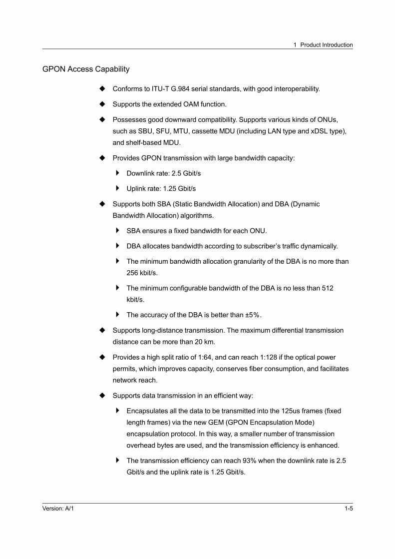
GPON Access Capability
u Conforms to ITU-T G.984 serial standards, with good interoperability.
u Supports the extended OAM function.
u Possesses good downward compatibility. Supports various kinds of ONUs,
such as SBU, SFU, MTU, cassette MDU (including LAN type and xDSL type),
and shelf-based MDU.
u Provides GPON transmission with large bandwidth capacity:
4 Downlink rate: 2.5 Gbit/s
4 Uplink rate: 1.25 Gbit/s
u Supports both SBA (Static Bandwidth Allocation) and DBA (Dynamic
Bandwidth Allocation) algorithms.
4 SBA ensures a fixed bandwidth for each ONU.
4 DBA allocates bandwidth according to subscriber’s traffic dynamically.
4 The minimum bandwidth allocation granularity of the DBA is no more than
256 kbit/s.
4 The minimum configurable bandwidth of the DBA is no less than 512
kbit/s.
4 The accuracy of the DBA is better than ±5%.
u Supports long-distance transmission. The maximum differential transmission
distance can be more than 20 km.
u Provides a high split ratio of 1:64, and can reach 1:128 if the optical power
permits, which improves capacity, conserves fiber consumption, and facilitates
network reach.
u Supports data transmission in an efficient way:
4 Encapsulates all the data to be transmitted into the 125us frames (fixed
length frames) via the new GEM (GPON Encapsulation Mode)
encapsulation protocol. In this way, a smaller number of transmission
overhead bytes are used, and the transmission efficiency is enhanced.
4 The transmission efficiency can reach 93% when the downlink rate is 2.5
Gbit/s and the uplink rate is 1.25 Gbit/s.
Version: A/1 1-5

AN5116-06B Optical Line Terminal Equipment Product Description
u Supports IEEE 1588V2 to implement the high-precision clock and time
synchronization in the network and meet the service demands.
1.2.2 Interface Type
The AN5116-06B supports various physical interface types, as shown in Figure 1-2.
Figure 1-2 Physical Interfaces of the AN5116-06B
The functions of various interfaces on the AN5116-06B are shown in Table 1-1.
Table 1-1 Interfaces of the AN5116–06B
Interface Class Interface Type Function
Uplink interface
10GE optical interfaceProvides 10GE Ethernet uplink optical
interface.
GE optical interfaceProvides GE Ethernet uplink optical
interface.
GE electrical interfaceProvides GE Ethernet uplink electrical
interface.
STM-1 optical interfaceProvides connection to the STM-1 optical
interface of the transmission equipment.
E1 electrical interfaceProvides connection to the E1 interface of
the transmission equipment.
Subscriber
interface
EPON optical interface Provides EPON subscriber interface.
10G EPON optical interface Provides 10G EPON subscriber interface.
GPON optical interface Provides GPON subscriber interface.
1-6 Version: A/1

1 Product Introduction
Table 1-1 Interfaces of the AN5116–06B (Continued)
Interface Class Interface Type Function
GE optical interfaceProvides GE Ethernet cascade optical
interface.
GE electrical interfaceProvides GE Ethernet cascade optical
interface.
Management
interface
FE interface Supports out-of-band GUI management.
10GE / GE interface Supports in-band GUI management.
RJ-45 interface (using the RS-
232 interface protocol)
Supports out-of-band local CLI
management.
External clock
interfaceClock coaxial interface
Provides input and output of the external
BITS clock.
Alarm interface RJ-45 interfaceTransports subrack alarm signals to the
PDP.
1.2.3 Support to IPv6 Protocol
The AN5116-06B supports the transparent transmission of IPv6 services, the IPv4/
v6 dual stack technology, and the network management system for the IPv6
equipment. While maintaining the current network architecture, it supports the
coexistence of the IPv4 and IPv6 services to enable smooth evolution to IPv6.
IPv6 VLAN Functions
u Supports the transparent transmission of IPv4 / IPv6 services.
u Supports identifying the IPv4 and IPv6 packets, and sets different VLANs for
them.
IPv6 QoS Functions
u Supports identifying IPv6 packets, and sets different Ethernet priorities for Pv4
and IPv6 packets.
u Supports classification of the uplink service flow based on the following objects:
IPv6 source / destination address, IP protocol type (such as TCP, UDP, and
ICMPv6), IPv6 priority field (Traffic Class) and IPv6 flow label field (Flow Label).
Version: A/1 1-7
AN5116-06B Optical Line Terminal Equipment Product Description
u Supports the mapping between the classification of the uplink IPv6 service flow
and the uplink IPv6 service priority, and supports the Ethernet PRI field as the
priority ID.
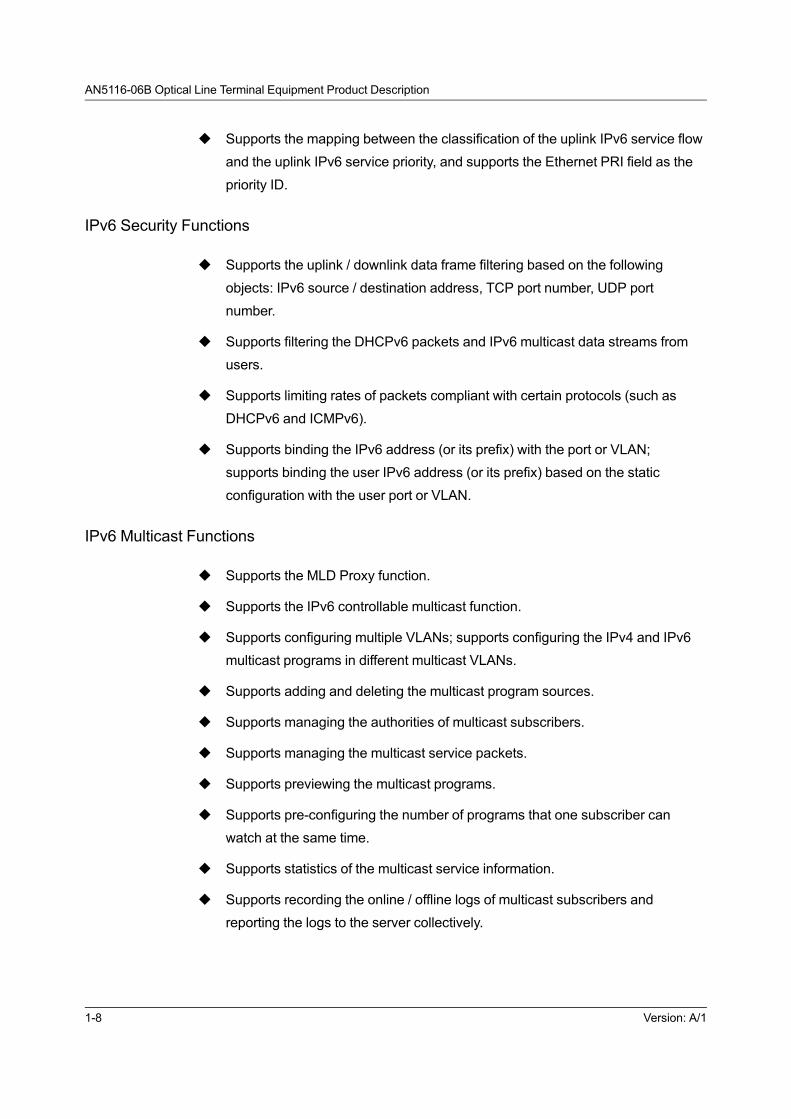
IPv6 Security Functions
u Supports the uplink / downlink data frame filtering based on the following
objects: IPv6 source / destination address, TCP port number, UDP port
number.
u Supports filtering the DHCPv6 packets and IPv6 multicast data streams from
users.
u Supports limiting rates of packets compliant with certain protocols (such as
DHCPv6 and ICMPv6).
u Supports binding the IPv6 address (or its prefix) with the port or VLAN;
supports binding the user IPv6 address (or its prefix) based on the static
configuration with the user port or VLAN.
IPv6 Multicast Functions
u Supports the MLD Proxy function.
u Supports the IPv6 controllable multicast function.
u Supports configuring multiple VLANs; supports configuring the IPv4 and IPv6
multicast programs in different multicast VLANs.
u Supports adding and deleting the multicast program sources.
u Supports managing the authorities of multicast subscribers.
u Supports managing the multicast service packets.
u Supports previewing the multicast programs.
u Supports pre-configuring the number of programs that one subscriber can
watch at the same time.
u Supports statistics of the multicast service information.
u Supports recording the online / offline logs of multicast subscribers and
reporting the logs to the server collectively.
1-8 Version: A/1

1 Product Introduction
IPv6 Port Isolation Functions
Supports port tagging via the DHCPv6 relay agent Option 18 / Option 37.
Other IPv6 Related Functions
Supports application programs related to the IPv6 protocol stack, such as the
network management system for IPv6 equipment and ICMPv6.
1.2.4 Multicast Function
The subscriber side and network side interfaces of the AN5116-06B support IGMP
V2 / V3 and MLD V1 / V2, and can provide subscribers with flexible multicast
solutions by virtue of the P2MP features of the PON.
Supported Multicast Functions
u Supports the IGMP V2 / V3 protocol.
u Supports the MLD V1 / V2 protocol.
u Supports the IGMP Proxy, IGMP Snooping, and MLD Proxy functions.
u Supports prejoin function which enables joining pre-configured multicast group
by automatically send joining message uplink.
u Supports preview function.
u Supports fast leave function.
u Supports multicast cascade when accessed in the EPON / GPON /10G EPON
mode.
u Supports cross-VLAN multicast.
u Supports management and identification of subscribers and program sources
based on multicast VLAN.
u Supports management of multicast group members via IGMP Proxy, IGMP
Snooping, and MLD Proxy messages.
u Supports dynamic management of joining / leaving and maintaining of multicast
members via IGMP / MLD Report / Leave and Query messages.
Version: A/1 1-9

AN5116-06B Optical Line Terminal Equipment Product Description
u Multicast statistics supported: count of subscriber joining / leaving multicast
group, total duration of watching and average duration of watching for each
multicast group or subscriber port.
u Supports online query of multicast information: ability to query the online
multicast groups, group members and status of the core switch card, the line
card and the ONU hierarchically.
u Supports multicast service CDR (Call Detail Record) function: including
subscriber port information, address of multicast group, joining and leaving time,
leaving pattern (forcibly or freely), and authority information.
u Supports controllable multicast function, and provides multicast subscriber-
based control, including information display, log and statistics of subscriber
joining / leaving multicast group events, which can effectively prevent protocol
attack, illegal multicast sources, illegal rebroadcasting, and illegal receiver to
guarantee operators' revenue.
Supported Multicast Routing Functions
u Supports the PIM-SM protocol.
u The AN5116-06B supports the PIM protocol, and connects the subscriber side
multicast router and the network side multicast router via the OLT uplink
interface.
u The AN5116-06B supports the PIM protocol, and it can work cooperatively with
Layer 2 IGMP multicast protocol.
4 In case that the multicast router does not support the IGMP protocol, the
uplink port of the AN5116-06B will enable the PIM protocol and connect to
the PIM router to set up the multicast route.
4 If the multicast router supports the IGMP, the AN5116-06B will provide
multicast services to the subscribers under the OLT via Layer 2 IGMP
functions.
u Supports PIM transparent transmission: The AN5116-06B can enable the PIM
transparent transmission to achieve transparent transmission for OLT network
side PIM router and the ONU side PIM router.
1-10 Version: A/1

1 Product Introduction
1.2.5 Voice Function
The AN5116-06B supports using the H.248, MGCP and SIP protocols to achieve
NGN voice functions. It can meet the requirements of carrier-class speech quality,
management and operations.
It uses the ONU to process NGN voice signals, and uses a softswitch or IMS to
perform call control, so as to provide VoIP access for analog subscriber lines.
Implementation Mode of NGN Voice Services
u Supports the ITU-T H.248, MGCP and SIP protocols to form a network with the
SoftSwitch and enable the NGN services.
u Supports the SIP protocol to form a network with the IMS and enable the NGN
services.
Supported NGN Voice Functions
u Provides the analogue line testing function for POTS interfaces.
u Supports multi-MGC list.
u The VLAN of each voice channel supports IEEE 802.1Q and PRI setting.
u Supports QinQ encapsulation for voice services.
u The call processing capability is 25k BHCA.
u The percent of call completed is larger than 99.999%.
u Supports IP telephone access for POTS subscribers.
u Supports T.30 / T.38-based FoIP (Fax over IP).
u Supports transparent transportation of MoIP.
u Supports pulse accounting and polarity-reversal accounting.
u Supports the IP CENTERX service.
u Supports the following intelligent services and user-defined services when
assisted by the softswitch or IMS:
4 Calling number identification (CNID) presentation and restriction.
4 Call waiting.
Version: A/1 1-11

AN5116-06B Optical Line Terminal Equipment Product Description
4 Three party service.
4 Alarm clock service.
4 Call forwarding (unconditional, busy and no answer).
4 Immediate hotline.
4 Outgoing call blocking.
4 Distinctive ring.
1.2.6 Layer 3 Routing Function
The equipment performs flexible Layer 3 routing functions, and supports multiple
routing protocols.
Supporting OSPF Dynamic Routing
u Fast convergence: Sends updated messages immediately when the network
topology architecture changes to enable synchronization in the autonomous
system.
u Loopback free: The OSPF calculates the route according to the collected link
status information using the shortest-path tree algorithm, and the algorithm
itself ensures that no loopback routes will be generated.
u Area division: The network of the autonomous system is divided into areas for
management. Thus the routing information transmitted between areas is
simplified, and the occupied network bandwidth is reduced.
u Equal-cost multi-path routing: Provides multiple equal-cost routes leading to the
same destination.
u Route level: Four levels of routes are used, and the sequence of priority is
described as follows (from higher to lower): intra-area route, inter-area route,
external route of type 1, and external route of type 2.
u Message authentication: Provides interface-based message authentication, so
as to ensure the security of route calculation.
u Multicast transmission: Supports the multicast address.
u The maximum number of dynamic routes is 4000.
1-12 Version: A/1

1 Product Introduction
Supporting RIP Dynamic Routing
u Supports RIP1 and RIP2 routing protocols.
u Supports external route tags: Performs flexible control of routes according to
route tags in the routing policy.
u The messages carry the mask information, and the route aggregation and
CIDR are supported.
u Supports setting the next hop, and the system can select the optimum address
of the next hop in the broadcast network.
u Supports authentication of protocol messages: Provides two authentication
modes, i.e., PAP-based clear-test authentication and MD5 authentication, so as
to enhance the security.
u Supports two message transmission modes: broadcast and multicast.
Supporting Static Routing
u Supports configuring static routes manually, and the Metric of the route is 0.
u The maximum number of static routes is 1000.
1.2.7 VLAN Function
The equipment provides powerful VLAN stacking and VLAN translation functions. It
can manage various subscribers' services effectively and enhance the network
security.
QinQ VLAN / VLAN Stacking Functions Supported by the Equipment
VLAN (Virtual Local Area Network) is a data exchange technology that logically
divides the local area network equipment into a network segment to form a virtual
working group.
Version: A/1 1-13
AN5116-06B Optical Line Terminal Equipment Product Description
The standard for QinQ VLAN/VLAN stacking is IEEE802.1ad, which is upgraded
from the IEEE802.1Q standard for VLAN. Its core concept is to encapsulate the
VLAN tag of the subscriber’s private network in a service VLAN tag of public
network so that the subscriber’s traffic crosses the provider’s backbone network
with two layers of tags. This provides subscribers with a relatively simple Layer 2
VPN tunnel, and can effectively overcome the VLAN ID addressing space limit of 4k
addresses.
The QinQ VLAN functions supported by the AN5116-06B are described as follows:
u Supports subscriber and service differentiation through VLANs.
u Supports setting the subscriber’s SVLAN based on card, PON port, or ONU.
u Supports VLAN number extension.
By adding QinQ VLANs, the number of VLANs is increased to 4096×4096 on
the basis of existing VLANs.
u Supports flexible QinQ features:
The system can add inner or outer VLAN based on the value of source MAC
address, destination MAC address, source IP address, destination IP address,
L4 source port number, L4 destination port number, Ethernet type, inner VLAN
ID, outer VLAN ID, service type, time-to-live, protocol type, L1 CoS, and L2
CoS.
u Supports selective QinQ for one port.
Supports basic QinQ and selective QinQ at the same time on a port: allowing
both double-tagged and single-tagged services.
VLAN Translation Functions Supported by the Equipment
VLAN translation means that the OLTor ONU equipment translates subscriber side
VLAN tags into network side VLAN tags. This function can reduce carriers’
maintenance workload and protect the distribution layer network and the core
network.
The VLAN translation function provided by the AN5116-06B can be in one of the
following three forms:
u 1:1 translation:
1-14 Version: A/1
1 Product Introduction
The uplink data VLANs of each subscriber are translated into the
corresponding network side VLANs. That is, the subscriber data VLANs
correspond to network side VLANs one by one.
u N:1 translation:
The VLAN aggregation function. In the uplink direction, a number of uplink
VLANs are aggregated and translated into a unique network-side VLAN; in the
downlink direction, the network-side VLAN is reversely mapped into multiple
VLANs on the subscriber side.
u Hybrid translation:
The combination of the 1:1 VLAN translation and the N:1 VLAN translation is
supported.
1.2.8 QoS Guarantee
The equipment has a sound QoS guarantee mechanism and supports end-to-end
QoS solution for the entire network. For different clients and services, it provides
network services of different qualities, which lays the foundation for management of
various services.
QoS Capability of EPON
u Supports the uplink port’s flow-based policies, including packet filter, re-
direction, flow mirroring, traffic statistics, traffic monitoring, queue scheduling,
rate control, priority policing and translation.
u Supports the uplink port’s packet filtering and classification based on source
MAC address, destination MAC address, Ethernet type, VLAN, CoS, source IP
address, destination IP address, IP port and protocol type.
u The OLTsupports three queue scheduling mechanisms: SP, WRR and SP +
WRR; and each port has eight priority queues.
u Supports CoS remarking and CoS copy:
Changes the original CoS value in the subscriber’s data message, or copies
the CoS value of the CVLAN to the SVLAN.
u Supports flow labeling and shaping.
u Supports 1024 QoS rules.
Version: A/1 1-15

AN5116-06B Optical Line Terminal Equipment Product Description
u Supports rate control of ports.
u Supports bandwidth control of an EPON port, with a granularity of 32 kbit/s.
u The ONU only supports the single-LLID technology.
QoS Capability of 10G EPON
u Supports the uplink port’s flow-based policies, including packet filter, re-
direction, flow mirroring, traffic statistics, traffic monitoring, queue scheduling,
rate control, priority policing and translation.
u Supports the uplink port’s packet filtering and classification based on source
MAC address, destination MAC address, Ethernet type, VLAN, CoS, source IP
address, destination IP address, IP port and protocol type.
u The OLTsupports three queue scheduling mechanisms: SP, WRR and SP +
WRR; and each port has eight priority queues.
u Supports CoS remarking and CoS copy:
Changes the original CoS value in the subscriber’s data message, or copies
the CoS value of the CVLAN to the SVLAN.
u Supports flow labeling and shaping.
u Supports 1024 QoS rules.
u Supports rate control of ports.
u Supports bandwidth control of an 10G EPON port, with a granularity of 8 kbit/s.
u The ONU only supports the single-LLID technology.
QoS Capability of GPON
u Supports the uplink port’s flow-based policies, including packet filter, re-
direction, flow mirroring, traffic statistics, traffic monitoring, queue scheduling,
rate control, priority policing and translation.
u Supports the uplink port’s packet filtering and classification based on source
MAC address, destination MAC address, Ethernet type, VLAN, CoS, source IP
address, destination IP address, IP port and protocol type.
u The OLTsupports three queue scheduling mechanisms: SP, WRR and SP +
WRR; and each port has eight priority queues.
u Supports CoS remarking and CoS copy:
1-16 Version: A/1

1 Product Introduction
Changes the original CoS value in the subscriber’s data message, or copies
the CoS value of the CVLAN to the SVLAN.
u Supports flow shaping, and supports dynamic adjustment of the traffic output
rate. The OLT performs data buffering, and sends out the data when available
bandwidth exists.
u Supports traffic policing, monitoring a certain kind of traffic that enters a certain
interface.
u Supports 1024 QoS rules.
u Supports the DBA (Dynamic Bandwidth Allocation) algorithm with a bandwidth
control granularity of 32 kbit/s.
u Provides flexible QoS and SLA functions:
Classifies priority queues according to MAC address, 802.1p priority, 802.1Q
VLAN tag, IP ToS, IP address, and TCP / UDP address; supports up to eight
service levels.
u Supports the uplink port’s flow-based rate limiting and mirroring.
u Supports T-CONTservice scheduling of type 1 to type 5.
u Provides uplink DBA and SBA functions, supporting both SR (Status Report)
mode and NSR (None Status Report) mode of DBA.
u The ONU supports the multi-T-CONT technology.
Each ONU supports up to eight T-CONTs, which are classified based on source
MAC address, destination MAC address, source IP address, destination IP
address, TCP, UDP, ToS, CoS, Ethernet type and protocol type.
1.2.9 Security Mechanism
Designed with carrier-class reliability, the equipment can fully guarantee the security
of subscribers' services.
System Side Security Insurance Measures
u Supports L2 to L7 packet filtering, performing illegal frame filtering based on
source MAC address, destination MAC address, source IP address, destination
IP address, port No., Ethernet type, protocol type, VLAN and VLAN range, so
as to prevent prevent illegal attempts to access the Internet.
Version: A/1 1-17
AN5116-06B Optical Line Terminal Equipment Product Description
u Supports protection against DOS attack to enhance the anti-attack capability.
u Supports ACL (Access Control List)-based permission / denial control
functions.
u Supports protection against ICMP (Internet Control Message Protocol) / IP
message attack.
u Supports protection against ARP (Address Resolution Protocol) attack.
u Both GUI and CLI network management systems can provide operator
accounts with different operating rights, so as to ensure operating security of
the network management system.
u Supports automatic reporting of ONU SN and MAC address to the network
management system.
u Supports multiple validity authentication modes of ONU, including based on the
physical ID, logical ID (without password), logical ID (with password), physical
ID / logical ID (with password), physical ID / logical ID (without password),
password, physical ID / physical password, etc.
u Supports broadcast storm control.
u Supports frame filtering and rate limiting.
u Supports loop test.
Subscriber Side Security Measures
u Supports access security control through DHCP Option 82 and PPPOE+. The
AN5116-06B can insert physical information into protocol messages of DHCP
request dial or PPPOE dial. When used in combination with a verifying system,
it can effectively and dynamically control subscriber access to specific network
resources, so as to greatly facilitate troubleshooting and attack positioning.
u Supports DHCP snooping. The ONU snoops subscriber information such as
MAC address, IP address, lease time and VLAN ID, so as to trace and locate
DHCP subscriber’s IP address and port by establishing and maintaining a
DHCP snooping binding table. In addition, it directly discards illegal messages
(ARP spoofing messages and the messages that modify IP address randomly).
These illegal messages are not compliant with the binding table entries.
Therefore, it guarantees DHCP environment integrity and consistency.
1-18 Version: A/1
1 Product Introduction
u Supports limit on the maximum number of MAC addresses learned, to prevent
MAC attack.
u Supports limit on the number of MAC addresses that access a single LAN
interface of an ONU.
u Supports limit on the number of multicast groups that a single LAN interface of
an ONU can join.
u Supports port binding, such as dynamic binding of FE interface and MAC
address, to guarantee validity of subscribers accessing the network.
u Supports AES-128 encryption and decryption algorithm to guarantee the
security of subscribers' data.
1.2.10 Reliability Design
System reliability is a major concern in the system design, software design and
hardware design of the AN5116-06B. The equipment provides sound redundancy
protection of power supply, fans, cards and interfaces, and optical path protection
switching mechanism, so as to ensure the normal operation of the equipment.
Card Protection
u Supports hot insertion of cards.
u Supports 1+1 active / standby switching function of the core switch cards to
enable seamless switching. The service interruption duration is less than 50ms
in the active / standby switching. After the switching of the core switch cards is
completed, you need not modify the configuration of the uplink interfaces,
which facilitates the user’s maintenance and management operations.
u Supports 1+1 redundancy protection for the uplink cards, and supports the
Trunk protection, dual-homing protection and MSTP protection for the uplink
interfaces.
4 When the uplink cards are set to 1+1 active / standby protection, the
interfaces of the two uplink cards are one-to-one protected.
¡ If the HU4A card is used as the uplink card, the equipment can
provide up to four 10GE uplink ports.
Version: A/1 1-19

AN5116-06B Optical Line Terminal Equipment Product Description
¡ If the GU6F card is used as the uplink card, the equipment can
provide up to six GE uplink ports.
¡ If the HU1A card is used as the uplink card, the equipment can
provide up to four GE uplink ports and one 10GE uplink port.
¡ If the HU2A card is used as the uplink card, the equipment can
provide up to two GE uplink ports and two 10GE uplink ports.
4 When the uplink ports are set to the Trunk mode, the bandwidth of uplink
ports can be extended and load equalization for interfaces in the Trunk
group is performed automatically. When a port in the Trunk group fails, the
flow of the failed port is automatically shared between other ports of the
Trunk group. The twelve GE uplink ports of the two uplink cards can form
maximally six Trunk groups and each Trunk group can support maximally
12 member ports. The 10GE uplink ports of the uplink cards can make up
maximally two 10GE uplink Trunk groups.
4 When the uplink ports are set to dual-homing protection, the two uplink
ports are connected to the IP bearer network via two sets of uplink
equipment to perform dual-homing protection. When one of the two links
fails, the services on the failed link will be automatically switched to the
other link, so that traffic remains unblocked.
4 When the uplink FE / GE interfaces of the AN5116-06Bs are connected to
form an MSTP ring network between the equipment, the demand of
service protection can be met and the optical fiber resources can be saved.
When link faults occur, a new connected network without the redundancy
path can be formed.
u Supports the inter-card protection for the TDM cards.
PON Protection
u Supports 1:1 protection for any PON ports, including different PON ports inside
one chip, PON ports in different chips on the same PON interface card, and the
PON ports on different PON interface cards in the same equipment.
u Supports the switching of Type B and Type C defined by the CTC standards;
the service interruption period during protection switching on the optical link is
less than 200 ms.
u Supports both the automatic switching and the forced switching.
1-20 Version: A/1

1 Product Introduction
Power Supply Protection
u Two power supply cards work for dual-power input and provide protection
against reverse polarity connection.
u The power supply cards support a distributed power-fed mode and all cards are
fed with power independently. Any fault in one card will not influence the other
cards. This greatly improves equipment reliability and stability.
Fan Protection
Provides fan running indicator LEDs to indicate the running status of fans.
1.2.11 Maintainability and Manageability
The equipment provides four network management functions: configuration
management, security management, performance management and fault
management. These functions together guarantee network QoS and facilitate users’
routine maintenance and fault diagnosis.
Management and Maintenance Measures
u Supports local and remote management measures.
u Supports GUI and CLI network management systems, and performs uniform
management of OLTs and ONUs via the UNM2000 developed by FiberHome.
u Supports in-band and out-of-band management modes.
u Supports SNMP.
u Supports the Telnet protocol for remote access to and management of the
equipment.
u Supports multiple management IP addresses / VLANs, and allows multiple
management servers to manage the same equipment simultaneously.
Terminal Management
u Supports the remote management of ONUs via the OLT (as the proxy of the
network management system). The OLT manages the remote EPON ONU
using the OAM extension protocol, and manages the remote GPON ONU using
the OMCI protocol.
Version: A/1 1-21

AN5116-06B Optical Line Terminal Equipment Product Description
u Supports pre-configuration of an ONU by the OLT. When the pre-configured
ONU gets registered, the OLTwill authorize the ONU and apply the pre-
configured data to the ONU automatically. This makes service configuration
more convenient.
u Supports automatic detection and testing of the ONU.
u Supports multiple authentication modes of ONU, including those based on
password, physical ID (without password), physical ID (with password), logical
ID (without password), logical ID (with password), physical ID + logical ID
(without password), and physical ID + logical ID (with password), etc.
u Supports interconnection with carrier’s management system, and receives
configuration from the operator’s resource management system.
Alarm Management
u Provides additional alarm information to help users find causes of the alarms
and identify the solution.
u Supports the system log function which can record the key configuration
changes to the system to assist fault analysis and isolation.
u Supports signaling tracing of speech to facilitate isolation of voice service
faults.
u Supports PSTN line quality and performance testing which can isolate
telephone line faults.
u Provides performance supervision and detection of optical power levels to
facilitate optical line maintenance.
u Supports local and remote end loopback tests to isolate subscriber line faults.
Performance Management
u Supports output of various statistic report forms, such as performance statistics
report form and alarm statistics report forms, to facilitate routine maintenance.
u The network management system supports collection, query and analysis of
performance data.
1-22 Version: A/1

1 Product Introduction
Security Management
The management system allows different levels of management authority to be
defined on a per user basis using the user management setting table.
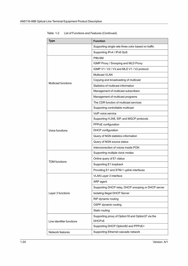
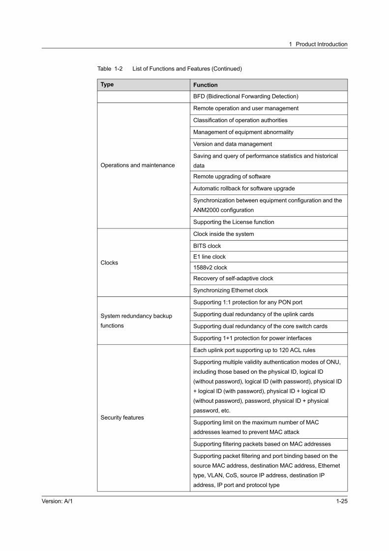
1.3 List of Functions and Features
See Table 1-2 for the functions supported by the AN5116-06B.
Table 1-2 List of Functions and Features
Type Function
Access features
EPON access
GPON access
10G EPON access
Ethernet access
E1/STM-1 access
EPON/10G EPON/GPON access EPON/10G EPON/GPON terminal management
Layer 2 switching functions
Supporting 802.1Q VLAN
Supporting selective QinQ (VLAN Stacking)
Independent learning of MAC addresses
Shared learning of MAC addresses
Globally clearing Layer 2 forwarding table
Supporting the OLT forwarding data based on the MAC
address
Supporting configuring the aging time of the MAC
addresses for the OLTand ONU
Supporting Layer 2 port dynamic aggregation and the
LACP
Supporting STP protocol (IEEE802.1D), RSTP protocol
(IEEE 802.1w), and MSTP protocol (IEEE 802.1s)
Port mirroringSupporting ingress and egress mirroring
Supporting flow mirroring
Port trunking
Supporting IEEE 802.3ad.
Supporting up to six trunk groups; up to 12 member ports
can be assigned to a trunk group.
Port isolationSupporting EPON / GPON / 10G EPON port isolation
Supporting the uplink port isolation
QoS functions Supporting two rate three color based on traffic
Version: A/1 1-23
AN5116-06B Optical Line Terminal Equipment Product Description
Table 1-2 List of Functions and Features (Continued)
Type Function
Supporting single rate three color based on traffic
Supporting IPv4 / IPv6 QoS
Multicast functions
PIM-SM
IGMP Proxy / Snooping and MLD Proxy
IGMP V1 / V2 / V3 and MLD V1 / V2 protocol
Multicast VLAN
Copying and broadcasting of multicast
Statistics of multicast information
Management of multicast subscribers
Management of multicast programs
The CDR function of multicast services
Supporting controllable multicast
Voice functions
VoIP voice service
Supporting H.248, SIP, and MGCP protocols
PPPoE configuration
DHCP configuration
Query of NGN statistics information
Query of NGN source status
Interconnection of voices inside PON
TDM functions
Supporting multiple clock modes
Online query of E1 status
Supporting E1 loopback
Providing E1 and STM-1 uplink interfaces
Layer 3 functions
VLAN Layer 3 interface
ARP agent
Supporting DHCP relay, DHCP snooping or DHCP server
Isolating illegal DHCP Server
RIP dynamic routing
OSPF dynamic routing
Static routing
Line identifier functions
Supporting proxy of Option18 and Option37 via the
DHCPv6
Supporting DHCP Option82 and PPPoE+
Network features Supporting Ethernet cascade network
1-24 Version: A/1
1 Product Introduction
Table 1-2 List of Functions and Features (Continued)
Type Function
BFD (Bidirectional Forwarding Detection)
Operations and maintenance
Remote operation and user management
Classification of operation authorities
Management of equipment abnormality
Version and data management
Saving and query of performance statistics and historical
data
Remote upgrading of software
Automatic rollback for software upgrade
Synchronization between equipment configuration and the
ANM2000 configuration
Supporting the License function
Clocks
Clock inside the system
BITS clock
E1 line clock
1588v2 clock
Recovery of self-adaptive clock
Synchronizing Ethernet clock
System redundancy backup
functions
Supporting 1:1 protection for any PON port
Supporting dual redundancy of the uplink cards
Supporting dual redundancy of the core switch cards
Supporting 1+1 protection for power interfaces
Security features
Each uplink port supporting up to 120 ACL rules
Supporting multiple validity authentication modes of ONU,
including those based on the physical ID, logical ID
(without password), logical ID (with password), physical ID
+ logical ID (with password), physical ID + logical ID
(without password), password, physical ID + physical
password, etc.
Supporting limit on the maximum number of MAC
addresses learned to prevent MAC attack
Supporting filtering packets based on MAC addresses
Supporting packet filtering and port binding based on the
source MAC address, destination MAC address, Ethernet
type, VLAN, CoS, source IP address, destination IP
address, IP port and protocol type
Version: A/1 1-25

AN5116-06B Optical Line Terminal Equipment Product Description
Table 1-2 List of Functions and Features (Continued)
Type Function
Supporting protection against DoS attacks
1-26 Version: A/1

2 Product Application
The following introduces the network description, technical application, and site
application of the AN5116-06B.
Network Introduction
Network Application
Version: A/1 2-1

AN5116-06B Optical Line Terminal Equipment Product Description
2.1 Network Introduction
The AN5116-06B is suitable for the FTTH / FTTC / FTTB / FTTO application.
Usually it is placed in a residential community or the central office.
Figure 2-1 shows the network diagram of the AN5116-06B.
Figure 2-1 Network Diagram of the AN5116-06B
2.2 Network Application
The following introduces the network application of the equipment.
2.2.1 Triple Play Application
The AN5116-06B supports the following three triple play solutions:
u EPON / 10G EPON triple play solution
The EPON / 10G EPON ONU uses different VLANs to classify different service
flows which are mapped to the same LLID and transported to the AN5116-06B
via the EPON / 10G EPON line.
2-2 Version: A/1

2 Product Application
u GPON single GEM port triple play solution
Supports classifying service flows based on Ethernet type, VLAN ID of
subscriber side messages and subscriber side 802.1p domain, and supports
control of service flows.
u GPON multiple GEM port triple play solution
Classifies different service flows by different GEM ports, maps different
services to different GEM ports according to the VLAN ID, 802.1p, or physical
port, and then delivers them to the AN5116-06B via the GPON line for
processing.
The AN5116-06B can provide subscribers simultaneously with multimedia services
such as data, voice and video services, and provide QoS guarantees accordingly.
See Figure 2-2 for an illustration of the triple play network.
Figure 2-2 The Triple Play Application of the AN5116-06B
2.2.2 MSTP Service Application
The MSTP is compatible with the STP and RSTP functions, and improves the two
technologies. The MSTP can implement fast convergence, and also can provide
better load sharing function for the redundancy link, and is applicable in the network
needing the service protection. But it is not recommended that users use the MSTP
at modes supporting many subscribers.
Version: A/1 2-3

AN5116-06B Optical Line Terminal Equipment Product Description
The AN5116-06B supports the MSTP service application. The MSTP divides a
Layer 2 network into multiple domains, and multiple independent spanning trees are
generated in each domain, so as to eliminate the loops. In addition, the MSTP
introduces the multi-instance technology. It maps each VLAN into the corresponding
instance, so as to share the traffic load between different VLANs. See Figure 2-3 for
the network of the MSTP service application.
Figure 2-3 Network of the AN5116-06B in MSTP Service
2.2.3 TDM Service Application
The AN5116-06B supports the TDM service application. It protects investment in
traditional TDM network, and uses the CES technology to enable TDM over IP, so
as to achieve the all-IP network architecture.
The AN5116-06B supports both asynchronous and synchronous clock modes and
provides a highly reliable transport solution for synchronization information and E1
services. See Figure 2-4 for the network of the TDM service application.
2-4 Version: A/1

2 Product Application
Figure 2-4 Network of the AN5116-06B in TDM Service
Through the E1 interface, the system can access the TDM services of the enterprise
private line users, and the CBU transmits the data and TDM services to the OLT
side at the same time. The OLT identifies and forwards the data and TDM services,
and then transmits them to the SDH network at the upper level via the E1 / STM-1
interface.
2.2.4 Residence and Home Application
Along with the application of the FTTx technology in the intelligent residence and
home, users can enjoy abundant network resources and excellent service quality
without leaving their homes.
In the residence and home application, the AN5116-06B supports the LAN, SFU, or
xDSL MDU. See Figure 2-5 for an illustration of the residence and home application.
Version: A/1 2-5

AN5116-06B Optical Line Terminal Equipment Product Description
Figure 2-5 Application of the AN5116-06B in Residential Districts and Families
u For the application from the central office to the cub near the home or office, it is
recommended that users use the FTTC access mode. In this mode, the
services can be transmitted to the home or office from the curb, so as to provide
subscribers with voice, data, and video services.
u For the application in the building that has been configured with the twisted-pair
cables, it is recommended that users use the FTTB access mode. The fiber is
accessed into the MDU equipment inside the building after it enters the building,
and then the services are transmitted to various subscribers via the twisted-pair
cables, so as to provide subscribers with voice, data, and video services inside
the building.
2-6 Version: A/1

2 Product Application
u For the application in the relatively decentralized suburban environment, it is
recommended that users use the FTTH access mode. In this mode, voice, data,
and video services are provided through a single fiber for subscribers via the
SFU equipment.
2.2.5 Small Cell Bearing Application
With the rapid popularization of the mobile intelligent terminals, the increasing
mobile data services are laying a big pressure of traffic on the operators' macro cell
network. It becomes an urgent problem to divide the traffic pressure by grading at
different levels.
The application of the Small Cell can effectively share the traffic of the macro cell
network. The data traffic is channelized inside the access network, and then sent
back to the core network, which can largely save the network resources for 3G/4G
transmission. Meanwhile, the Small Cell is small-sized and can be applied in various
scenarios conveniently. Operators can use it as the platform for many customized
services (such as message pushing and hot spot covering services) to form a new
profit-making point.
Figure 2-6 shows the bearer network of Small Cell.
Figure 2-6 Application of the AN5116-06B in the Small Cell
Version: A/1 2-7

AN5116-06B Optical Line Terminal Equipment Product Description
By setting VLANs, the AN5116-06B can access the common broadband data
service and the 3G / 4G mobile data service at the same time. This improves the
network capacity and covering capability, so as to bear the mobile data service
better.
The AN5116-06B supports the BC mode of the 1588 V2 clock model. It is used
together with the ONU supporting the 1588 V2 protocol to provide the clock
information for the Small Cell to ensure a high-precision clock frequency and phase
synchronization and finally ensure the clock synchronization between the terminal
equipment and the AN5116-06B.
2.2.6 High Bandwidth Access Application
Along with the development of the Triple Play application, the EPON / GPON
technology has been quite mature and is now widely used in the network
construction and project improvement of operators. However, users have increasing
demands on application of various high bandwidth value-added services. It
becomes the new orientation for the development of the FTTx technology to access
more subscribers and guarantee higher bandwidth.
The AN5116-06B supports the 10G EPON interface card. The 10G EPON interface
card provides eight EPON interfaces complaint with the IEEE 802.3av/802.3ah
standard. Each EPON interface supports a transmission distance of at least 20 km,
and supports a maximum split ratio of 1:128 within the optical power budget. It can
be applied in the broadband data convergence in the MAN. By accessing the 10G
EPON ONU, the equipment provides the FE / GE interface to solve the problem of
limited optical fiber resource in the network construction.
The 10G EPON technology of the AN5116-06B can be widely used in the
construction of the campus network or the enterprise network. Here we take the
campus network as an example, as shown in Figure 2-7.
2-8 Version: A/1

2 Product Application
Figure 2-7 Application of the AN5116-06B in High Bandwidth Access
It is recommended that you use the AN5006-07 / 09 / 10, the AN5506-07 / 09 / 10,
or the AN5200-07 / 10 as the ONU, which can provide 24 voice and data interfaces
at most.
Version: A/1 2-9

AN5116-06B Optical Line Terminal Equipment Product Description
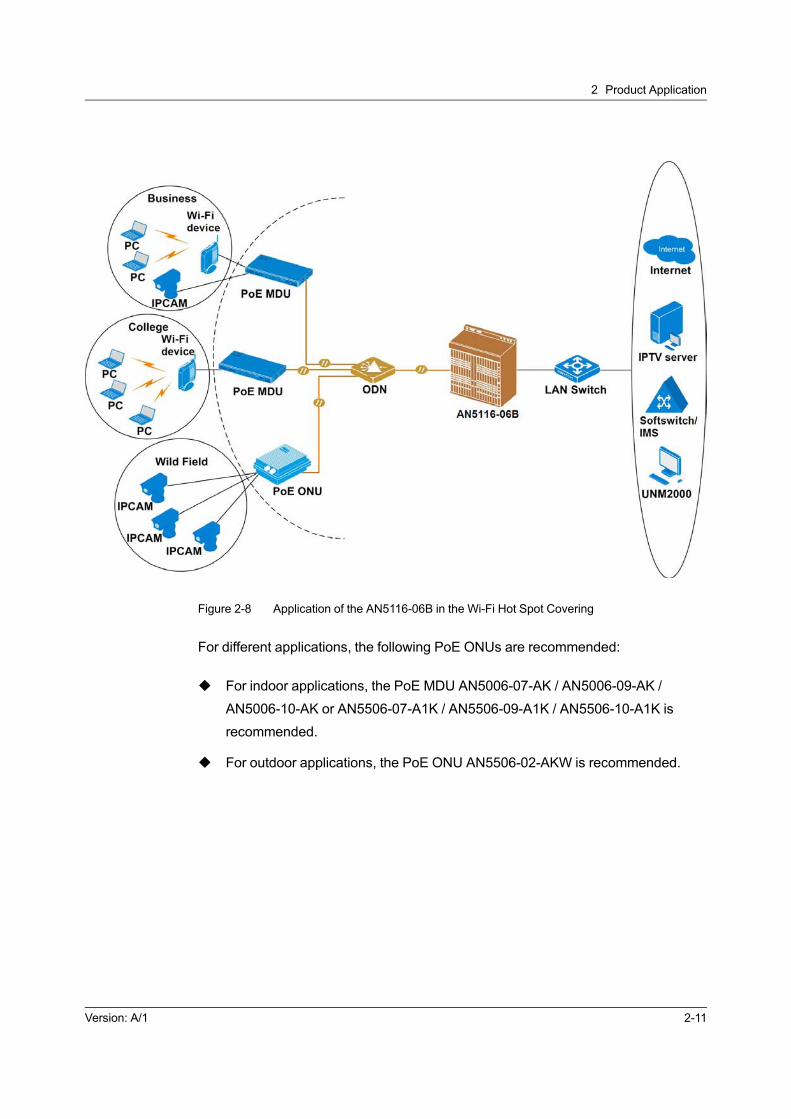
2.2.7 Wi-Fi Hot Spot Covering Application
The equipment provides the power supply for the Wi-Fi equipment and monitoring
equipment in some special circumstances via the PoE ONU, so as to solve the
problem of power supply difficulties in places such as the department stores,
communities and fields, where it is hard to arrange the Wi-Fi equipment. Compared
with the traditional local power supply mode, the equipment provides a power
supply measure which is cheap, flexible in deployment, and reliable. This can speed
up the progress of network construction, and enable rapid deployment of services.
The equipment supports the PoE ONUs of various types, and can be applied as
follows:
u By providing the power supply for the Wi-Fi equipment via the PoE ONU,
covers the public areas such as the department stores and community, and
supports the wireless access of the terminal devices such as the portable
computer and the mobile phone.
u By providing the power supply for the monitoring equipment via the PoE ONU,
implements the remote security monitoring. The collected monitoring data are
transmitted to the monitoring center via the equipment.
See Figure 2-8 for the network of the Wi-Fi hot spot covering application.
2-10 Version: A/1
2 Product Application
Figure 2-8 Application of the AN5116-06B in the Wi-Fi Hot Spot Covering
For different applications, the following PoE ONUs are recommended:
u For indoor applications, the PoE MDU AN5006-07-AK / AN5006-09-AK /
AN5006-10-AK or AN5506-07-A1K / AN5506-09-A1K / AN5506-10-A1K is
recommended.
u For outdoor applications, the PoE ONU AN5506-02-AKW is recommended.
Version: A/1 2-11


3 Product Composition
The following introduces the logical architecture, hardware structure, and software
architecture of the AN5116-06B.
Logical Architecture
Hardware Structure
Software Architecture
Version: A/1 3-1
AN5116-06B Optical Line Terminal Equipment Product Description
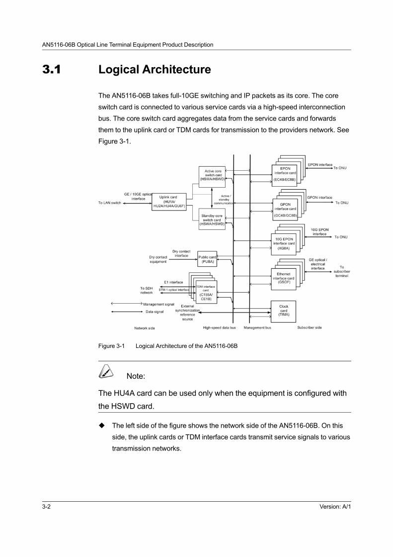
3.1 Logical Architecture
The AN5116-06B takes full-10GE switching and IP packets as its core. The core
switch card is connected to various service cards via a high-speed interconnection
bus. The core switch card aggregates data from the service cards and forwards
them to the uplink card or TDM cards for transmission to the providers network. See
Figure 3-1.
Figure 3-1 Logical Architecture of the AN5116-06B
Note:
The HU4A card can be used only when the equipment is configured with
the HSWD card.
u The left side of the figure shows the network side of the AN5116-06B. On this
side, the uplink cards or TDM interface cards transmit service signals to various
transmission networks.
3-2 Version: A/1
3 Product Composition
u The right side of the figure shows the subscriber side of the AN5116-06B. On
this side, the EPON / GPON / 10G EPON interface cards connect with the
ONUs via the ODN; and the Ethernet interface cards connect with the
subscriber or other Ethernet equipment sets via the cascade interfaces.
u The core switch cards manage other cards through the management bus.
3.2 Hardware Structure
The following introduces the hardware structure of the cabinet, PDP, subrack and
cards.
3.2.1 19-inch Cabinet
The following introduces the 19-inch cabinet used by the AN5116-06B.
3.2.1.1 Appearance
See Figure 3-2 for the appearance of the 19-inch cabinet.
Version: A/1 3-3

AN5116-06B Optical Line Terminal Equipment Product Description
Figure 3-2 Appearance of a 19-inch Cabinet
3.2.1.2 Dimension
The dimensions of a 19-inch cabinet are described as follows in terms of Height (H)
× Width (W) × Depth (D):
u 1600mm×600mm×600mm
u 2000mm×600mm×600mm
u 2200mm×600mm×600mm
u 2600mm×600mm×600mm
3-4 Version: A/1

3 Product Composition
3.2.1.3 Equipment Layout
According to their heights, the 19-inch cabinets can be classified into four types:
2600 mm cabinet, 2200 mm cabinet, 2000 mm cabinet, and 1600 mm cabinet. See
Figure 3-3 for the typical configurations of them respectively (unit: mm).
Figure 3-3 Typical Layout of a 19-inch Cabinet
Note:
If a cabinet is not fully configured, users should arrange the subracks
from the top down and reserve the space in the lower part for capacity
expansion in the future.
3.2.2 21-inch Cabinet (without the Anti-dust Screen)
The following introduces the 21-inch cabinet (without the anti-dust screen) used by
the AN5116-06B.
Version: A/1 3-5

AN5116-06B Optical Line Terminal Equipment Product Description
3.2.2.1 Appearance
The appearance of a 21-inch cabinet (without the anti-dust screen) is shown in
Figure 3-4.
Figure 3-4 Appearance of a 21-inch Cabinet (without the Anti-dust Screen)
3.2.2.2 Dimensions
The dimensions of 19-inch cabinets are described as follows in terms of Height (H)
× Width (W) × Depth (D):
u 1600mm × 600 mm × 300mm
u 2000 mm × 600 mm × 300mm
u 2200mm × 600 mm × 300mm
u 2600mm × 600 mm × 300mm
3-6 Version: A/1

3 Product Composition
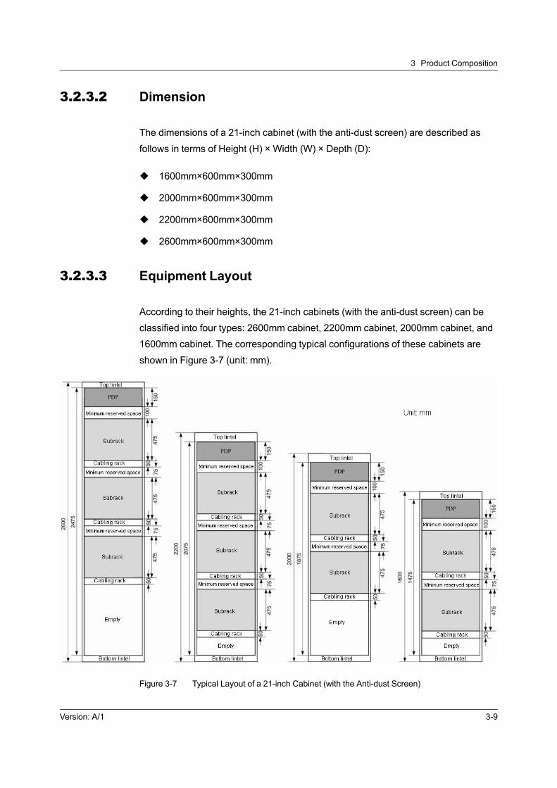
3.2.2.3 Equipment Layout
According to their heights, the 21-inch cabinets (without the anti-dust screen) can be
classified into four types: 2600mm cabinet, 2200mm cabinet, 2000mm cabinet, and
1600mm cabinet. The corresponding typical configurations of these cabinets are
shown in Figure 3-5 (unit: mm).
Figure 3-5 Typical Layout of a 21-inch Cabinet (without the Anti-dust Screen)
Note:
If a cabinet is not fully configured, users should arrange the subracks
from the top down and reserve the space in the lower part for capacity
expansion in the future.
Version: A/1 3-7
AN5116-06B Optical Line Terminal Equipment Product Description
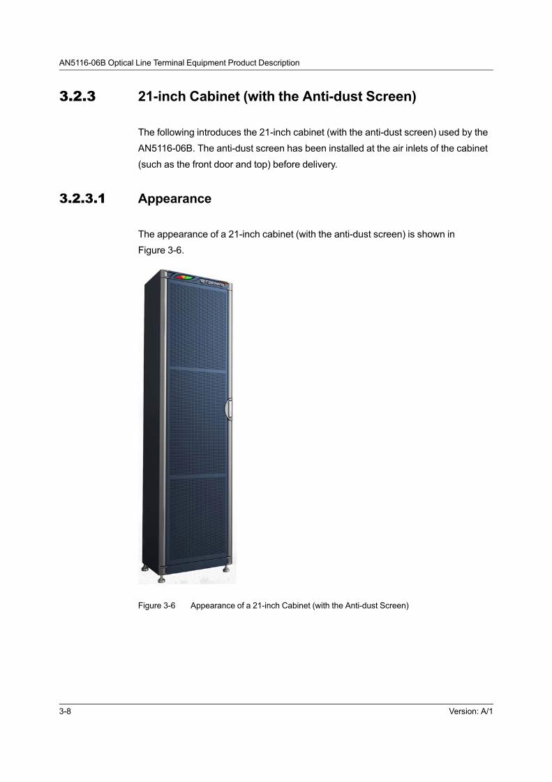
3.2.3 21-inch Cabinet (with the Anti-dust Screen)
The following introduces the 21-inch cabinet (with the anti-dust screen) used by the
AN5116-06B. The anti-dust screen has been installed at the air inlets of the cabinet
(such as the front door and top) before delivery.
3.2.3.1 Appearance
The appearance of a 21-inch cabinet (with the anti-dust screen) is shown in
Figure 3-6.
Figure 3-6 Appearance of a 21-inch Cabinet (with the Anti-dust Screen)
3-8 Version: A/1
3 Product Composition
3.2.3.2 Dimension
The dimensions of a 21-inch cabinet (with the anti-dust screen) are described as
follows in terms of Height (H) × Width (W) × Depth (D):
u 1600mm×600mm×300mm
u 2000mm×600mm×300mm
u 2200mm×600mm×300mm
u 2600mm×600mm×300mm
3.2.3.3 Equipment Layout
According to their heights, the 21-inch cabinets (with the anti-dust screen) can be
classified into four types: 2600mm cabinet, 2200mm cabinet, 2000mm cabinet, and
1600mm cabinet. The corresponding typical configurations of these cabinets are
shown in Figure 3-7 (unit: mm).
Figure 3-7 Typical Layout of a 21-inch Cabinet (with the Anti-dust Screen)
Version: A/1 3-9

AN5116-06B Optical Line Terminal Equipment Product Description
Note:
If a cabinet is not fully configured, users should arrange the subracks
from the top down and reserve the space in the lower part for capacity
expansion in the future.
3.2.4 PDP
The AN5116-06B uses the PDP of the following types for the corresponding
cabinets to provide eight branches of power supply (four active and four standby) for
the equipment.
u For a 19-inch cabinet, the PDP 3000064-1FHR1AA is used.
u For a 21-inch cabinet, the PDP 3000064-2FHR1AA is used.
3.2.4.1 Function
The PDP is used to perform the following functions:
u Power distribution function: Inducts eight channels of DC -48 V power (active
and standby) from the external (e.g. the power cabinet) and provides four sets
of redundant branch power rails (eight branch power rails in total). The
maximum output current of a single channel is 50 A.
u Alarm signal processing function: The PDP collects the alarm information from
the corresponding equipment via the four alarm convergence connectors,
provides corresponding audible alarm signals, illuminates the cabinet top
indicator LEDs, and outputs the alarm signals to higher-level equipment (such
as the head of row cabinet).
u Lightning protection module alarm reporting function: When the lightning
protection module fails, the PDP outputs the lightning protection failure alarm,
and then reports it to the network management system via the equipment.
u Lightning protection function: The PDP can effectively withstand surge current
of common mode 4kV / differential mode 2kV (1.2/50 us to 8/20 us hybrid wave)
on the power line.
3-10 Version: A/1

3 Product Composition
3.2.4.2 Appearance
See Figure 3-8 for the appearance of the PDP.
Figure 3-8 Appearance of the PDP
3.2.5 Subrack
The following introduces the appearance, structure, and layout of the subrack.
3.2.5.1 Appearance
The backplane of the AN5116-06B is located in the rear of the subrack. All cards of
the equipment are plugged from the front of the subrack and the front wiring mode is
used. Figure 3-9 shows the structure and components of the subrack.
Version: A/1 3-11

AN5116-06B Optical Line Terminal Equipment Product Description
(1) Mounting ear (2) Fan unit (3) Backplane
Figure 3-9 Subrack Structure
See Table 3-1 for description of each component of the subrack.
Table 3-1 Description of Subrack Structure
Number Description Function
(1) Mounting ear Secures the subrack in a 19-inch cabinet.
(2) Fan unit Facilitates air cooling for the equipment.
(3) BackplaneConnects each module and performs the function of
bus.
3.2.5.2 Slot Allocation and Typical Configuration
See Figure 3-10 for the slot allocation and typical configuration of the AN5116-06B
subrack.
3-12 Version: A/1

3 Product Composition
Figure 3-10 Subrack Slot Allocation and Typical Configuration
The AN5116-06B subrack has a total of 20 vertical slots.
u Slots 1 to 8 and 11 to 18 are for various service cards such as EPON interface
cards, 10G EPON interface cards, GPON interface cards, TDM interface cards,
and Ethernet interface cards.
u Slots 9 and 10 are slightly wider and are for core switch cards.
u Slots 19 and 20 are on the rightmost part of the subrack. Half as high as other
slots, the two slots are designed for uplink cards.
Version: A/1 3-13

AN5116-06B Optical Line Terminal Equipment Product Description
3.2.6 Card
The AN5116-06B card functions are shown in Table 3-2 .
Table 3-2 Card Function List
Card Type Card Name Function Description
Uplink card
HU1A
Uplinks the signals in the EPON / GPON system;
provides four GE uplink optical / electrical interfaces
and one 10GE uplink optical interface.
HU1B
Uplinks the signals in the EPON / GPON system and
enables Ethernet clock synchronization; provides four
GE uplink optical / electrical interfaces and one 10GE
uplink optical interface.
HU2A
Uplinks the signals in the EPON / GPON system;
provides two GE uplink optical / electrical interfaces
and two 10GE uplink optical interfaces.
GU6FUplinks the signals in the EPON / GPON system;
provides six GE uplink optical / electrical interfaces.
GU6B
Uplinks the signals in the EPON / GPON system and
enables Ethernet clock synchronization; provides six
GE uplink optical / electrical interfaces.
HU4AUplinks the signals in the EPON / GPON system;
provides four 10GE / GE uplink optical interfaces.
EPON interface
card
EC4B
Accesses subscriber services; provides four EPON
service interfaces. Supports the split ratio up to 1:64
within the limits of the optical power budget.
EC8B
Accesses subscriber services; provides eight EPON
service interfaces. Supports the split ratio up to 1:64
within the limits of the optical power budget.
ECOB
Accesses subscriber services; provides 16 EPON
service interfaces. Supports the split ratio up to 1:64
within the limits of the optical power budget.
10G EPON
interface cardXG8A
Accesses subscriber services; provides eight 10G
EPON service interfaces. Supports the split ratio up to
1:128 within the limits of the optical power budget.
GPON interface
cardGC4B
Accesses subscriber services; provides four GPON
service interfaces. Supports the split ratio up to 1:128
within the limits of the optical power budget.
3-14 Version: A/1

3 Product Composition
Table 3-2 Card Function List (Continued)
Card Type Card Name Function Description
GC8B
Accesses subscriber services; provides eight GPON
service interfaces. Supports the split ratio up to 1:128
within the limits of the optical power budget.
GCOB
Accesses subscriber services; provides 16 GPON
service interfaces. Supports the split ratio up to 1:128
within the limits of the optical power budget.
TDM interface
card
CE1BUplinks the TDM service signals; supports uplinking of
32 E1 signals.
C155AUplinks the TDM service signals; supports uplinking of
one STM-1 signal.
Ethernet
interface cardGSOF
Uplinks or cascades the Ethernet service signals;
provides 16 GE optical / electrical interfaces.
Clock card TIMA
Inputs and outputs various clock synchronization
signals, including input and output of one 1PPS+TOD
signal, input of one 1588V2 signal, input of two BITS
clock signals and output of one BITS clock signal.
Core switch card
HSWA
Aggregates, switches and manages service flows in
the EPON / GPON / 10G EPON system; processes
Layer 2 and Layer 3 protocols; provides fault
management, configuration management, and
performance management for the equipment.
Provides a Console interface for local management.
HSWD
Aggregates, switches and manages service flows in
the EPON / GPON / 10G EPON system; processes
Layer 2 and Layer 3 protocols; provides fault
management, configuration management, and
performance management for the equipment.
Supports large capacity data exchange. Provides a
Console interface for local management.
3.3 Software Architecture
The AN5116-06B’s software module is composed of the core switch software, the
service interface card software, the uplink card software, and the network
management software. See Figure 3-11.
Version: A/1 3-15
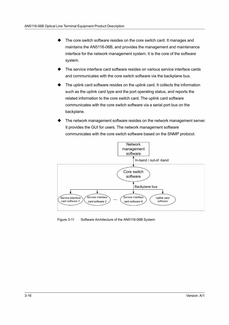
AN5116-06B Optical Line Terminal Equipment Product Description
u The core switch software resides on the core switch card. It manages and
maintains the AN5116-06B, and provides the management and maintenance
interface for the network management system. It is the core of the software
system.
u The service interface card software resides on various service interface cards
and communicates with the core switch software via the backplane bus.
u The uplink card software resides on the uplink card. It collects the information
such as the uplink card type and the port operating status, and reports the
related information to the core switch card. The uplink card software
communicates with the core switch software via a serial port bus on the
backplane.
u The network management software resides on the network management server.
It provides the GUI for users. The network management software
communicates with the core switch software based on the SNMP protocol.
Figure 3-11 Software Architecture of the AN5116-06B System
3-16 Version: A/1

4 System Management
The following introduces the system management mode of the AN5116-06B.
Management Mode
CLI Network Management System
The UNM2000
Version: A/1 4-1

AN5116-06B Optical Line Terminal Equipment Product Description
4.1 Management Mode
The AN5116-06B supports various management modes for equipment maintenance
and monitoring, and includes the following modes:
u According to whether the network management system is connected with the
equipment network interface, the management modes can be classified as
follows.
4 In the local management mode, the network management system
computer is directly connected with the managed equipment via its
network management interface, so as to manage the equipment. The
HSWA / HSWD card’s Console port is the port used in the local
management mode.
4 In the remote management mode, the network management system
computer is connected with the equipment via the LAN or the Internet, so
as to manage the equipment. The GE or 10GE interfaces or the EMS out-
of-band network interface of the uplink card are the Telnet remote
management interfaces.
u According to whether the management path and the service path are isolated
physically, the management modes can be classified as follows.
4 In the out-of-band mode, the management information is transported via
an independent physical path and does not use the subscriber service
path.
4 In the in-band mode, the management information is transported via the
subscriber service path provided by the managed equipment.
u According to whether the management system uses a GUI, the management
modes can be classified as follows.
4 The GUI mode provides GUIs for operators. It is easy to understand and
operate.
4 The CLI mode uses the CLI. This may be too complex for the casual or
occasional operators.
4-2 Version: A/1
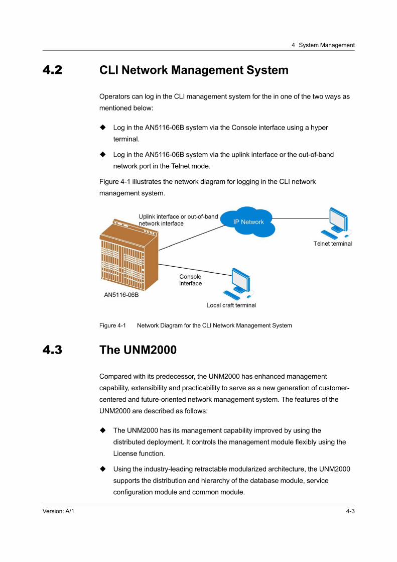
4 System Management
4.2 CLI Network Management System
Operators can log in the CLI management system for the in one of the two ways as
mentioned below:
u Log in the AN5116-06B system via the Console interface using a hyper
terminal.
u Log in the AN5116-06B system via the uplink interface or the out-of-band
network port in the Telnet mode.
Figure 4-1 illustrates the network diagram for logging in the CLI network
management system.
Figure 4-1 Network Diagram for the CLI Network Management System
4.3 The UNM2000
Compared with its predecessor, the UNM2000 has enhanced management
capability, extensibility and practicability to serve as a new generation of customer-
centered and future-oriented network management system. The features of the
UNM2000 are described as follows:
u The UNM2000 has its management capability improved by using the
distributed deployment. It controls the management module flexibly using the
License function.
u Using the industry-leading retractable modularized architecture, the UNM2000
supports the distribution and hierarchy of the database module, service
configuration module and common module.
Version: A/1 4-3
AN5116-06B Optical Line Terminal Equipment Product Description
u As a new generation of network management system, the UNM2000 aims to
provide users with customer-centered experience.
u As an independent application program, the UNM2000 can be installed in
various operating systems based on different databases. That is, it is
compatible with multiple operating systems.
u The UNM2000 can provide both superior solutions for large-scale networks and
low-cost solutions for small and medium-sized networks.
u The UNM2000 can be run on the Windows, Linux and Solaris operating
systems. The performance of the client end and server end of the UNM2000 is
irrelevant to the operating system used.
4.3.1 Function
Configuration Management
The UNM2000 manages the configurations of all the equipment in the network, and
users can configure various items for the equipment via the UNM2000. The
UNM2000 provides a universal configuration GUI for all services. Users can
configure various services such as data, voice, IPTV and CATV services collectively
on the UNM2000, which greatly enhances the efficiency of configuration.
Topology Management
In the topology management, the state of connection between the managed NEs is
displayed in form of topograph, and users can learn about the network condition of
the entire network in a real time manner and monitor the operation state by viewing
the topology view.
Alarm Management
The system can monitor the faults and abnormalities that occur during the operation
of the equipment in a real time manner using the alarm management function.
Meanwhile, it provides detailed information about the alarms and analyzing
measures to assistant in fault isolation and troubleshooting.
4-4 Version: A/1

4 System Management
Event Management
Events occur during the normal operation of the system, and they act as active
notices to users. The UNM2000 divides the events into four levels based on the
order of severity: urgent, major, minor and prompt.
Performance Management
The UNM2000 supports viewing the real-time performance data and comprehensive
management performance data. It can monitor the real-time performance of relevant
equipment in the access network and compare the instant performance, which
helps users to learn of the current operation state and basic performance of the
network, prevent network accidents and plan the operation network appropriately.
Security Management
The purpose of security management is to prevent illegal users from logging in the
network management system and prevent legal users from operating the network
management system beyond their authorization, so as to guarantee the safe
operation of the network. The UNM2000 provides a sound security management
mechanism to guarantee the network security by means of authorization and
domain division, access control, log management, and so on.
4.3.2 Operating Environment
Server End
The hardware configuration requirements for the UNM2000 server varies with the
network scale. See Table 4-1 for the details.
Table 4-1 Hardware Configuration Requirement for the Server End
Network Scale CPU Clock Rate CPU Quantity Memory Size Hard Disk Space
Equivalent to more
than 1000 OLTs, with
fully-configured
ONUs under them.
Intel E7-8837 (8-
core), 2.6GHZ4 64G 4*600GB
Equivalent to 500 to
1000 OLTs, with fully-
configured ONUs
under them.
Intel XeonE7-
4610V2 (8-core), 2.
3GHZ
4 32G 4*600GB
Version: A/1 4-5

AN5116-06B Optical Line Terminal Equipment Product Description
Table 4-1 Hardware Configuration Requirement for the Server End (Continued)
Network Scale CPU Clock Rate CPU Quantity Memory Size Hard Disk Space
Equivalent to 100 to
500 OLTs, with fully-
configured ONUs
under them.
Intel XeonE5-
2667V2 (8-core), 3.
3GHZ
2 32G 2*600GB
Equivalent to less
than 100 OLTs, with
fully-configured
ONUs under them.
Intel XeonE5-
2430V2 (6-core) 2.
5GHz
2 16G 2*600GB
Table 4-2 lists the software requirements for the network management system
server computer.
Table 4-2 Software Configuration Requirements for the Server End
Configuration Item Requirement
Operating System
Windows Server 2008 R2 Standard 64-bit
Linux Enterprise11 64-bit
Solaris 11 64-bit
Database SQL Server 2008 R2
JRE JRE 1.6.0
Client End
Table 4-3 presents the hardware configuration requirements for the UNM2000 client
end.
Table 4-3 Hardware Configuration Requirement for the Client End
Network Scale CPU Clock Rate CPU Quantity Memory Size Hard Disk Space
Equivalent to more
than 1000 OLTs, with
fully-configured
ONUs under them.
Intel XeonE5-
2637V2 (4-core), 3.
5GHZ
1 8G 2*500GB
Equivalent to 500 to
1000 OLTs, with fully-
configured ONUs
under them.
Intel XeonE5-
2637V2 (4-core), 3.
5GHZ
1 8G 2*500GB
4-6 Version: A/1
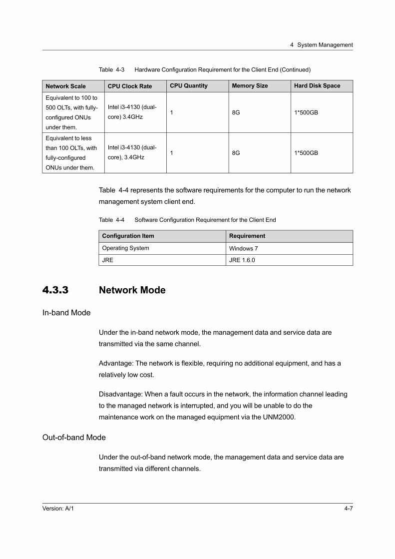
4 System Management
Table 4-3 Hardware Configuration Requirement for the Client End (Continued)
Network Scale CPU Clock Rate CPU Quantity Memory Size Hard Disk Space
Equivalent to 100 to
500 OLTs, with fully-
configured ONUs
under them.
Intel i3-4130 (dual-
core) 3.4GHz1 8G 1*500GB
Equivalent to less
than 100 OLTs, with
fully-configured
ONUs under them.
Intel i3-4130 (dual-
core), 3.4GHz1 8G 1*500GB
Table 4-4 represents the software requirements for the computer to run the network
management system client end.
Table 4-4 Software Configuration Requirement for the Client End
Configuration Item Requirement
Operating System Windows 7
JRE JRE 1.6.0
4.3.3 Network Mode
In-band Mode
Under the in-band network mode, the management data and service data are
transmitted via the same channel.
Advantage: The network is flexible, requiring no additional equipment, and has a
relatively low cost.
Disadvantage: When a fault occurs in the network, the information channel leading
to the managed network is interrupted, and you will be unable to do the
maintenance work on the managed equipment via the UNM2000.
Out-of-band Mode
Under the out-of-band network mode, the management data and service data are
transmitted via different channels.
Version: A/1 4-7

AN5116-06B Optical Line Terminal Equipment Product Description
Advantage: The management data channel is independent from the service data
channel, and the management is not restricted by the state of the service data
channel. Compared with the in-band mode, the out-of-band network mode can
provide a more reliable equipment management channel. When a fault occurs in the
managed equipment, the UNM2000 can identify the equipment information in a
timely manner for real-time monitoring.
Disadvantage: Under the out-of-band network mode, an independent channel
should be set up for the UNM2000 to manage the equipment in the network. The
maintenance channel independent from the service channel should be provided.
Accordingly, the network construction cost is relatively high.
Network Example
The typical network mode for the UNM2000 is characterized by collective
deployment with a single host. The UNM2000 is connected with the NEs in the out-
of-band mode. See Figure 4-2 for the network diagram.
Figure 4-2 Network Example
4-8 Version: A/1

5 Technical Specification and Standard
The following introduces the equipment’s technical specifications and applicable
standards.
Performance Parameter
Interface Specifications
Mechanical Dimensions and Weight
Power Supply and Power Consumption
Equipment Room Requirement
Standard and Protocol
Version: A/1 5-1

AN5116-06B Optical Line Terminal Equipment Product Description
5.1 Performance Parameter
The following introduces related performance parameters of the AN5116-06B.
5.1.1 Overall Performance
Table 5-1 The Overall Performance of the Equipment
Item Specification
Core switch card capacity408Gbit/s (equipped with the HSWA card)
960Gbit/s (equipped with the HSWD card)
Backplane bus capacity 5.12Tbit/s
Maximum transmission distance 20km
Maximum split ratio of EPON 1:64
Maximum split ratio of 10G EPON 1:128
Maximum split ratio of GPON 1:128
Core switch card active / standby switching
time<50ms
Active/standby switching time for the uplink
card<50ms
Optical protection switching time (TYPEB /
TYPEC / TYPED)<50ms
Table 5-2 The DBA Performance of the Equipment
Item Specification
Minimum bandwidth allocation granularity ≤256kbit/s
Minimum configurable bandwidth ≥512kbit/s
Accuracy Better than ±5%
Table 5-3 The Ethernet Service Performance of the Equipment
Item Specification
Through-
put
EPON system
Uplink throughput: ≥ 900 Mbit/s (the packet length is between 64-
byte and 1518-byte; the split ratio is 1:32)
Downlink throughput: ≥ 950 Mbit/s (any packet length)
GPON
system
Uplink throughput: ≥ 1100 Mbit/s
Downlink throughput: ≥ 2400 Mbit/s
5-2 Version: A/1

5 Technical Specification and Standard
Table 5-3 The Ethernet Service Performance of the Equipment (Continued)
Item Specification
10G EPON
system
When the 10G / 1G-EPON interface only accesses the 10G / 1G-
EPON ONU, the downlink throughput is ≥ 8.3 Gbit/s, and the
uplink throughput is ≥ 900 Mbit/s.
When the 10G / 10G-EPON interface only accesses the 10G /
10G-EPON ONU, the downlink throughput is ≥ 8.3 Gbit/s, and the
uplink throughput is ≥ 8 Gbit/s.
Latency
EPON /
GPON
system
The uplink mean transmission latency (when traffic flow is no
more than 90% of the system throughput) is less than 1.5 ms
under the split ratio of 1:32 (the packet length is between 64-byte
and 1518-byte).
The downlink mean transmission latency (when traffic flow is no
more than 90% of the system throughput) is less than 1 ms (any
packet length)
10G EPON
system
The uplink mean transmission latency (when traffic flow is no
more than 90% of the PON interface throughput) is less than 1.5
ms under the split ratio of 1:32.
The downlink mean transmission latency (when traffic flow is no
more than 90% of the PON interface throughput) is less than 1
ms.
Packet
loss rate
EPON /
GPON
system
The uplink packet loss rate under the split ratio 1:32 (the uplink
and downlink traffic both being 1 Gbit/s) is less than 10% (any
packet length).
The downlink packet loss rate (the uplink and downlink traffic both
being 1 Gbit/s) is less than 5% (any packet length).
10G EPON
system
When the 10G / 10G-EPON interface only accesses the 10G /
10G-EPON ONU under the split ratio 1:32 (the uplink and
downlink traffic both being 10 Gbit/s), the PON interface uplink
packet loss rate is less than 10%, and the PON interface downlink
packet loss rate is less than 17%.
When the 10G / 10G-EPON interface only accesses the 10G /
10G-EPON ONU under the split ratio 1:32 (the uplink and
downlink traffic being 1Gbit/s and 10 Gbit/s respectively), the
PON interface uplink packet loss rate is less than 20%, and the
PON interface downlink packet loss rate is less than 17%.
Long-term packet loss rateUnder a certain traffic flow (90% of the throughput), the long-term
(24 hours) packet loss rate of Ethernet service is 0.
Version: A/1 5-3

AN5116-06B Optical Line Terminal Equipment Product Description
Table 5-4 The Voice Service Performance of the Equipment
Item Specification
Voice encoding dynamic
switching period<60ms
Voice interruption and
jitter occurrence0
Objective evaluation of
voice
Under very good network condition: PSQM average value < 1.5
Under bad network condition (packet loss rate = 1%, jitter = 20 ms,
delay = 100 ms): PSQM average value < 1.8
Under very bad network condition (packet loss rate = 5%, jitter =
60 ms, delay = 400 ms): PSQM average value < 2.0
Subjective evaluation of
voice
Under very good network condition: The packaging interval of G.
711A RTP packets is 20 ms; MOS > 4.0
Under bad network condition (packet loss rate = 1%, jitter = 20 ms,
delay = 100 ms): The packaging interval of G.711A RTP packets is
20 ms; MOS > 3.5
Under very bad network condition (packet loss rate = 5%, jitter =
60 ms, delay = 400 ms), the packaging interval of G.711A RTP
packets is 20 ms; MOS > 3.0.
Encoding rate
For G.711, the encoding rate = 64 kbit/s
For G.729a, the encoding rate < 18 kbit/s
For G.723.1 (5.3), the encoding rate < 18 kbit/s
For G.723.1 (6.3), the encoding rate < 15 kbit/s
Loopback delayFor G.729a, the loopback delay < 150 ms
For G.723.1, the loopback delay < 200 ms
Call loss rate The call lost rate is less than 0.01%.
Table 5-5 The TDM Service Performance of the Equipment
Item Specification
Bit error ratio Under normal condition, BER of an E1 path in 24 hours is 0.
Latency (EPON system)Under the normal condition, the latency from the ONU's E1
interface to the OLT's E1 uplink port is less than 1.5 ms.
Latency (GPON system)Under the normal condition, the latency from the ONU's E1
interface to the OLT's E1 uplink port is less than 1.5 ms.
Jitter transmission
features
When 0 Hz ≤ f ≤ 40 Hz, the gain is equal to 0.5 dB.
When 40 Hz ≤ f ≤ 400Hz, the gain decreases as frequency
increases.
When f ≥ 400 Hz, the gain is equal to -19.5 dB.
5-4 Version: A/1
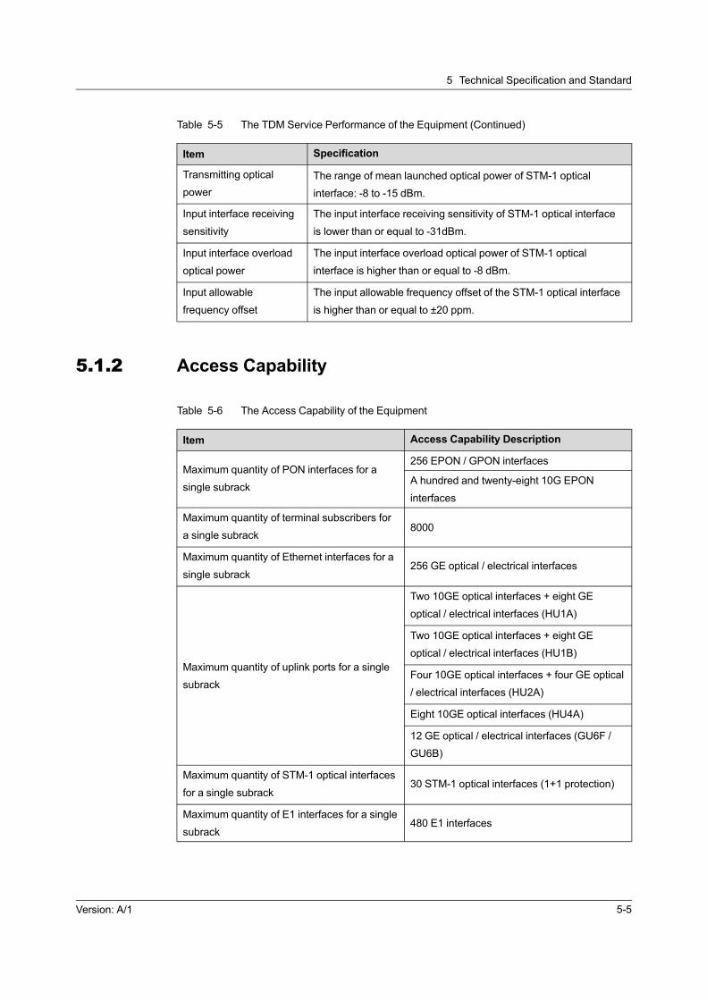
5 Technical Specification and Standard
Table 5-5 The TDM Service Performance of the Equipment (Continued)
Item Specification
Transmitting optical
power
The range of mean launched optical power of STM-1 optical
interface: -8 to -15 dBm.
Input interface receiving
sensitivity
The input interface receiving sensitivity of STM-1 optical interface
is lower than or equal to -31dBm.
Input interface overload
optical power
The input interface overload optical power of STM-1 optical
interface is higher than or equal to -8 dBm.
Input allowable
frequency offset
The input allowable frequency offset of the STM-1 optical interface
is higher than or equal to ±20 ppm.
5.1.2 Access Capability
Table 5-6 The Access Capability of the Equipment
Item Access Capability Description
Maximum quantity of PON interfaces for a
single subrack
256 EPON / GPON interfaces
A hundred and twenty-eight 10G EPON
interfaces
Maximum quantity of terminal subscribers for
a single subrack8000
Maximum quantity of Ethernet interfaces for a
single subrack256 GE optical / electrical interfaces
Maximum quantity of uplink ports for a single
subrack
Two 10GE optical interfaces + eight GE
optical / electrical interfaces (HU1A)
Two 10GE optical interfaces + eight GE
optical / electrical interfaces (HU1B)
Four 10GE optical interfaces + four GE optical
/ electrical interfaces (HU2A)
Eight 10GE optical interfaces (HU4A)
12 GE optical / electrical interfaces (GU6F /
GU6B)
Maximum quantity of STM-1 optical interfaces
for a single subrack30 STM-1 optical interfaces (1+1 protection)
Maximum quantity of E1 interfaces for a single
subrack480 E1 interfaces
Version: A/1 5-5

AN5116-06B Optical Line Terminal Equipment Product Description
5.1.3 Reliability Specifications
See Table 5-7 for the card reliability specifications; see Table 5-8 for the equipment
reliability specifications.
Table 5-7 The Card Reliability Specifications
Card MTBF (hour) MTBF (year) Failure Rate (ppm)
HSWA 148037.24 16.90 6.755
HSWD 148037.24 16.90 6.755
HU1A 339725.81 38.78 2.944
HU1B 327412.37 37.37 3.054
HU2A 339274.78 38.73 2.947
HU4A 339968.27 38.91 2.942
GU6F 358163.67 40.89 2.792
GU6B 312578.24 35.68 3.199
EC4B 149971.26 17.12 6.668
EC8B 150966.18 17.23 6.624
ECOB 150865.43 17.21 6.701
GC4B 146411.36 16.71 6.830
GC8B 146606.07 16.74 6.821
GCOB 146738.59 16.76 6.811
XG8A 150847.2 17.22 6.63
C155A 147353.56 16.89 6.790
TIMA 146503.37 16.73 6.818
CE1B 143050.78 16.33 6.990
GSOF 181156.80 20.68 5.520
Note 1: The MTTR (mean time to repair) of each card is 0.5 hour.
Table 5-8 The Equipment Reliability Specifications
Configuration
ModelMTBF (hour) MTBF (year)
Failure Rate
(ppm)Availability
IP uplink, 4096
lines125906.76 14.37 7.942 0.99999205
Note 1: The MTTR (mean time to repair) of the entire system is 0.5 hour.
5-6 Version: A/1

5 Technical Specification and Standard
5.2 Interface Specifications
The following introduces the specifications of the interfaces on the equipment.
5.2.1 Specifications of Interfaces on the EC4B / EC8B /ECOB Card
Table 5-9 Specifications of Interfaces on the EC4B / EC8B / ECOB Card
Item 1.25Gbit/s EPON Interface
Interface type SC / PC
Transmitter
Nominal bit rate 1.25 Gbit/s ± 100 ppm
Wavelength range 1480 nm to 1500 nm
Mean launched power (maximum) +7 dBm
Mean launched power (minimum) +2 dBm
Average launched power of OFF
transmitter-39 dBm
Extinction ratio (minimum) +9 dB
Receiver
Nominal bit rate 1.25 Gbit/s ± 100 ppm
Wavelength range 1260 nm to 1360 nm
Receiver sensitivity (maximum) -27 dBm
Minimum overload power -3 dBm
5.2.2 Specifications of Interface on the XG8A Card
Table 5-10 Specifications of Interface on the XG8A Card
Item1.25 Gbit/s 10G EPON
Interface
10 Gbit/s 10G EPON
Interface
Interface type SC / PC SC / PC
Transmitter
Nominal bit rate 1.25 Gbit/s ± 100 ppm 10 Gbit/s ± 100 ppm
Wavelength range 1480 nm to 1500 nm 1574 nm to 1580 nm
Mean launched
power (maximum)+5 dBm +5 dBm
Mean launched
power (minimum)+2 dBm +2 dBm
Version: A/1 5-7
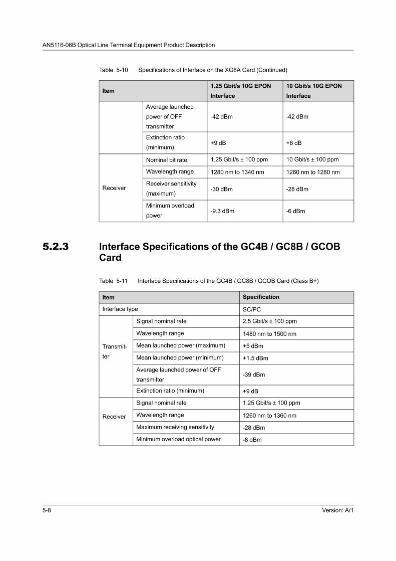
AN5116-06B Optical Line Terminal Equipment Product Description
Table 5-10 Specifications of Interface on the XG8A Card (Continued)
Item1.25 Gbit/s 10G EPON
Interface
10 Gbit/s 10G EPON
Interface
Average launched
power of OFF
transmitter
-42 dBm -42 dBm
Extinction ratio
(minimum)+9 dB +6 dB
Receiver
Nominal bit rate 1.25 Gbit/s ± 100 ppm 10 Gbit/s ± 100 ppm
Wavelength range 1280 nm to 1340 nm 1260 nm to 1280 nm
Receiver sensitivity
(maximum)-30 dBm -28 dBm
Minimum overload
power-9.3 dBm -6 dBm
5.2.3 Interface Specifications of the GC4B / GC8B / GCOBCard
Table 5-11 Interface Specifications of the GC4B / GC8B / GCOB Card (Class B+)
Item Specification
Interface type SC/PC
Transmit-
ter
Signal nominal rate 2.5 Gbit/s ± 100 ppm
Wavelength range 1480 nm to 1500 nm
Mean launched power (maximum) +5 dBm
Mean launched power (minimum) +1.5 dBm
Average launched power of OFF
transmitter-39 dBm
Extinction ratio (minimum) +9 dB
Receiver
Signal nominal rate 1.25 Gbit/s ± 100 ppm
Wavelength range 1260 nm to 1360 nm
Maximum receiving sensitivity -28 dBm
Minimum overload optical power -8 dBm
5-8 Version: A/1
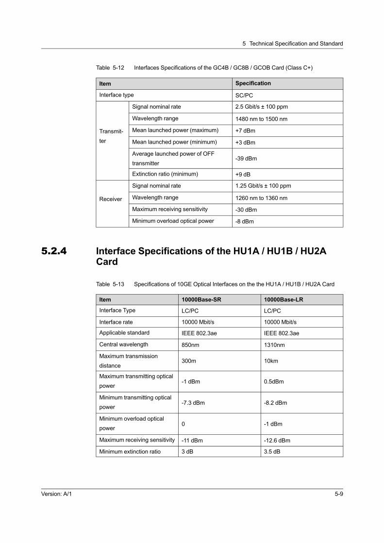
5 Technical Specification and Standard
Table 5-12 Interfaces Specifications of the GC4B / GC8B / GCOB Card (Class C+)
Item Specification
Interface type SC/PC
Transmit-
ter
Signal nominal rate 2.5 Gbit/s ± 100 ppm
Wavelength range 1480 nm to 1500 nm
Mean launched power (maximum) +7 dBm
Mean launched power (minimum) +3 dBm
Average launched power of OFF
transmitter-39 dBm
Extinction ratio (minimum) +9 dB
Receiver
Signal nominal rate 1.25 Gbit/s ± 100 ppm
Wavelength range 1260 nm to 1360 nm
Maximum receiving sensitivity -30 dBm
Minimum overload optical power -8 dBm
5.2.4 Interface Specifications of the HU1A / HU1B / HU2ACard
Table 5-13 Specifications of 10GE Optical Interfaces on the the HU1A / HU1B / HU2A Card
Item 10000Base-SR 10000Base-LR
Interface Type LC/PC LC/PC
Interface rate 10000 Mbit/s 10000 Mbit/s
Applicable standard IEEE 802.3ae IEEE 802.3ae
Central wavelength 850nm 1310nm
Maximum transmission
distance300m 10km
Maximum transmitting optical
power-1 dBm 0.5dBm
Minimum transmitting optical
power-7.3 dBm -8.2 dBm
Minimum overload optical
power0 -1 dBm
Maximum receiving sensitivity -11 dBm -12.6 dBm
Minimum extinction ratio 3 dB 3.5 dB
Version: A/1 5-9

AN5116-06B Optical Line Terminal Equipment Product Description
Table 5-14 Specifications of GE Optical Interfaces on the the HU1A / HU1B / HU2A Card
Item 1000Base-SX 1000Base-LX
Interface Type LC/PC LC/PC
Interface rate 1000 Mbit/s 1000 Mbit/s
Applicable standard IEEE 802.3z IEEE 802.3z
Central wavelength 850nm 1310nm
Maximum transmission
distance500m 20km
Maximum transmitting optical
power-4 dBm -3 dBm
Minimum transmitting optical
power-9.5 dBm -11.5 dBm
Minimum overload optical
power0 -3 dBm
Maximum receiving sensitivity -17 dBm -19 dBm
Minimum extinction ratio 9 dB 9 dB
Table 5-15 Specifications of Ethernet Electrical Interfaces on the the HU1A / HU1B / HU2A
Card
Item 10/100/1000Base-T
Interface Type RJ-45
Interface rate Auto-negotiated to 10 / 100 / 1000 Mbit/s
Transmission media CAT-5
Applicable standard IEEE 802.3-2005
Transmission distance 100m
5.2.5 Interface Specifications of the HU4A Card
Table 5-16 Ethernet Optical Interface Specifications of the HU4A Card
Item 10000Base-SR
Interface Type LC/PC
Interface rate 10000 Mbit/s
Applicable standard IEEE 802.3ae
Central wavelength 850 nm
Maximum transmission distance 300m
Maximum transmitting optical power -1 dBm
5-10 Version: A/1

5 Technical Specification and Standard
Table 5-16 Ethernet Optical Interface Specifications of the HU4A Card (Continued)
Item 10000Base-SR
Minimum transmitting optical power -6 dBm
Minimum overload optical power 0
Maximum receiving sensitivity -11 dBm
Minimum extinction ratio 3 dB
5.2.6 Interface Specifications of the GU6F / GU6B / GSOFCard
Table 5-17 Specifications of Ethernet Optical Interfaces on the GU6F / GU6B / GSOF Card
Item 1000Base-SX 1000Base-LX
Interface Type LC/PC LC/PC
Interface rate 1000 Mbit/s 1000 Mbit/s
Applicable standard IEEE 802.3z IEEE 802.3z
Central wavelength 850 nm 1310 nm
Maximum transmission
distance500m 20km
Maximum transmitting optical
power-4 dBm -3 dBm
Minimum transmitting optical
power-9.5 dBm -11.5 dBm
Minimum overload optical
power0 -3 dBm
Maximum receiving sensitivity -17 dBm -19 dBm
Minimum extinction ratio 9 dB 9 dB
Table 5-18 Specifications of Ethernet Electrical Interfaces on the GU6F / GU6B / GSOF Card
Item 10/100/1000Base-T
Interface Type RJ-45
Interface rate Auto-negotiated to 10 / 100 / 1000 Mbit/s
Transmission media CAT-5
Applicable standard IEEE 802.3-2005
Transmission distance 100m
Version: A/1 5-11

AN5116-06B Optical Line Terminal Equipment Product Description
5.2.7 Interface Specifications of the CE1B Card
Table 5-19 Interface Specifications of the CE1B Card
Item Specification
Pulse shapeAll marks of effective signals comply with pulse mask in Figure 5-
1.
Nominal frequency 2048 kbit/s ± 50 ppm
Pairs per directionThe outer conductor of the input port and output port of the coaxial
pair is connected to ground.
Test load impedance 75 Ω, resistive 120 Ω, resistive
Nominal peak voltage of amask (pulse) 2.37V 3V
Nominal peak voltage of amask (no pulse) 0±0.237V 0±0.3V
Nominal pulse width 244 ns
Ratio of the amplitudes of positive and negative
pulses at the centre of the pulse interval0.95 to 1.05
Ratio of the widths of positive and negative
pulses at the nominal half amplitude0.95 to 1.05
Code type HDB3
5.2.8 Interface Specifications of the C155A Card
Table 5-20 Interface Specifications of the C155A Card
Item Specification
Interface type SC/PC
Nominal bit rate 155 520 kbit/s
Application code S-1.1 L-1.1 L-1.2
Operating wavelength range1261 nm to
1360 nm1263 nm to 1360 nm
1480 nm to
1580 nm
Transmitter at
reference point
S
Source type MLM MLM SLM SLM
Maximum RMS width (s) 7.7 nm 3 nm - -
Maximum -20 dB width - - 1 nm 1 nm
Minimum side mode
suppression ratio- - 30 dB 30 dB
Maximum mean launched
power-8 dBm 0 0
5-12 Version: A/1

5 Technical Specification and Standard
Table 5-20 Interface Specifications of the C155A Card (Continued)
Item Specification
Minimum mean launched
power-15 dBm -5 dBm -5 dBm
Minimum extinction ratio 8.2 dB 10 dB 10 dB
Optical path
between S and
R
Attenuation range 0 to 12 dB 10 dB to 28 dB 10 dB to 28 dB
Maximum dispersion 96 ps/nm 246 ps/nm NA NA
Minimum optical return loss
of cable plant at S NA NA 20 dB
, including any connectors
Maximum discrete
reflectance between S and
R
NA NA -25 dB
Receiver at
reference point
R
Minimum sensitivity (BER
≤10-12)-28 dBm -34 dBm -34 dBm
Minimum overload (BER ≤
10-12)-8 dBm -10 dBm -10 dBm
Maximum optical path
penalty1 dB 1 dB 1 dB
maximum reflectance of
receiver, measured at RNA NA -25
5.2.9 Interface Specifications of the HSWA Card
Table 5-21 Interface Specifications of the HSWA Card
Item Specification
Interface type RJ-45
Interface standard Asynchronous EIA / TIA-232
Rate 9600 bit/s
Version: A/1 5-13
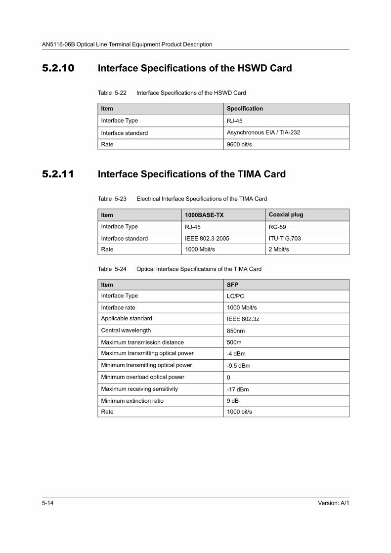
AN5116-06B Optical Line Terminal Equipment Product Description
5.2.10 Interface Specifications of the HSWD Card
Table 5-22 Interface Specifications of the HSWD Card
Item Specification
Interface Type RJ-45
Interface standard Asynchronous EIA / TIA-232
Rate 9600 bit/s
5.2.11 Interface Specifications of the TIMA Card
Table 5-23 Electrical Interface Specifications of the TIMA Card
Item 1000BASE-TX Coaxial plug
Interface Type RJ-45 RG-59
Interface standard IEEE 802.3-2005 ITU-T G.703
Rate 1000 Mbit/s 2 Mbit/s
Table 5-24 Optical Interface Specifications of the TIMA Card
Item SFP
Interface Type LC/PC
Interface rate 1000 Mbit/s
Applicable standard IEEE 802.3z
Central wavelength 850nm
Maximum transmission distance 500m
Maximum transmitting optical power -4 dBm
Minimum transmitting optical power -9.5 dBm
Minimum overload optical power 0
Maximum receiving sensitivity -17 dBm
Minimum extinction ratio 9 dB
Rate 1000 bit/s
5-14 Version: A/1

5 Technical Specification and Standard
5.3 Mechanical Dimensions and Weight
Table 5-25 Mechanical Dimensions and Weight of the Equipment
Item Dimensions (Height × Width × Depth) Weight
Cabinet
2600mm × 600 mm × 600mm 134kg
2200mm × 600 mm × 600mm 117kg
2000mm × 600 mm × 600mm 109kg
1600mm × 600 mm × 600mm 94kg
2600mm × 600 mm × 300mm 85kg
2200mm × 600 mm × 300mm 74kg
2000mm × 600 mm × 300mm 69kg
1600mm × 600 mm × 300mm 58kg
Empty subrack (including
the fan)471.65mm × 480.8mm × 262.7mm 20kg
Subrack (fully configured) 471.65mm × 480.8mm × 262.7mm 30kg
5.4 Power Supply and Power Consumption
See Table 5-26 for the power consumption of the AN5116-06B's cards under the
-48V DC power supply.
Table 5-26 Power Consumption of the Equipment's Cards
CardPower
ConsumptionCard
Power
Consumption
HSWA ≤40W C155A ≤ 40 W
HSWD ≤160W GU6F ≤ 10W
EC4B ≤ 40W HU1A ≤ 10W
ECOB ≤58W HU1B ≤20W
GC4B ≤ 40W HU2A ≤ 10W
EC8B ≤ 60W HU4A ≤20W
GC8B ≤ 50W GSOF ≤30W
GCOB ≤80W TIMA ≤10W
XG8A ≤108W Fan unit ≤ 196W
CE1B ≤ 40W GU6B ≤20W
Version: A/1 5-15

AN5116-06B Optical Line Terminal Equipment Product Description
5.5 Equipment Room Requirement
The following introduces the requirements on the equipment room for the AN5116-
06B.
5.5.1 Power Supply Requirement
u Equipment room voltage: -48 V DC (-40 V to -57 V).
u The equipment room should be equipped with the UPS power supply that can
run at least 8 hours continuously.
5.5.2 Working Environment
u Ground bearing of the equipment room:>600 kg/m2.
u No corrosive and solvent gas, and no dust in the atmosphere; no strong
electromagnetic field nearby.
u The dust in the environment should be non-conductive of both electricity and
magnetism, and noncorrosive; the dust (diameter > 5 μm) concentration index
should be ≤ 3×10⁴/m3.
u Grounding resistance: < 10 Ω.
u Atmospheric pressure: 86 kPa to 106 kPa
u Operating temperature: 0℃ to 45℃
u Storage temperature: -30℃ to 60℃
5.6 Standard and Protocol
The following introduces the standards and protocols that the equipment complies
with.
5-16 Version: A/1

5 Technical Specification and Standard
5.6.1 Environment Standard
Standard Number Name
ANSI/UL 94-2006Tests for Flammability of Plastic Materials for Parts in Devices and
Appliances (Proposal dated March 17, 2006)
BS EN 60950-1-2006Information technology equipment - Safety - General
requirements
BS EN 60950-22-2006Information technology equipment - Safety - Equipment installed
outdoors
ETSI EN 300 019-1-3
Environmental Engineering (EE); Environmental conditions and
environmental tests for telecommunications equipment; Part 1-3:
Classification of environmental conditions; Stationary use at
weatherprotected locations
IEC 60917-1Modular order for the development of mechanical structures for
electronic equipment practices - Part 1: Generic standard
IEC 60917-1-amd1
Amendment 1 - Modular order for the development of mechanical
structures for electronic equipment practices - Part 1: Generic
standard
IEC 60917-2
Modular order for the development of mechanical structures for
electronic equipment practices - Part 2: Sectional specification -
Interface co-ordination dimensions for the 25 mm equipment
practice
IEC 60917-2-1
Modular order for the development of mechanical structures for
electronic equipment practices - Part 2: Sectional specification -
Interface co-ordination dimensions for the 25 mm equipment
practice - Section 1: Detail specification - Dimensions for cabinets
and racks
IEC 60917-2-2
Modular order for the development of mechanical structures for
electronic equipment practices - Part 2: Sectional specification -
Interface co-ordination dimensions for the 25 mm equipment
practice - Section 2: Detail specification - Dimensions for
subracks, chassis, backplanes, front panels and plug-in units
IEC 60917-2-3
Modular order for the development of mechanical structures for
electronic equipment practices - Part 2-3: Sectional specification -
Interface co-ordination dimensions for the 25 mm equipment
practice - Extended detail specification - Dimensions for subracks,
chassis, backplanes, front panels and plug-in units
IEC 60950-22-2005Information technology equipment - Safety - Part 22: Equipment
to be installed outdoors
Version: A/1 5-17

AN5116-06B Optical Line Terminal Equipment Product Description
Standard Number Name
IEC 61587-1-2007
Mechanical structures for electronic equipment - Tests for IEC
60917 and IEC 60297 - Part 1: Climatic, mechanical tests and
safety aspects for cabinets, racks, subracks and chassis
IEC 61587-2-2000
Mechanical structures for electronic equipment - Tests for IEC
60917 and IEC 60297 - Part 2: Seismic tests for cabinets and
racks
IEC 61587-3-2006
Mechanical structures for electronic equipment - Tests for IEC
60917 and IEC 60297 - Part 3: Electromagnetic shielding
performance tests for cabinets, racks and subracks
UL 94-1996UL Standard for Safety Test for Flammability of Plastic Materials
for Parts in Devices and Appliances Fifth Edition
5.6.2 Electromagnetic Compatibility Standard
Standard Number Name
CISPR 22Information technology equipment – Radio Disturbance
characteristics – Limits and methods of measurement
CISPR 24Information technology equipment - Immunity characteristics -
Limits and methods of measurement
EN 300 386
Electromagnetic compatibility and Radio spectrum Matters
(ERM); Telecommunication network equipment; Electromagnetic
Compatibility (EMC) requirements
EN 55022Information technology equipment - Radio disturbance
characteristics - Limits and methods of measurement
EN 55024Information technology equipment - Immunity characteristics -
Limits and methods of measurement
EN 61000-4-2Electromagnetic compatibility (EMC) - Part 4 - 2: Electrostatic
discharge immunity test
EN 61000-4-3
Electromagnetic compatibility (EMC) - Part 4 - 3: Testing and
measurement techniques-Radiated, radio-frequency,
electromagnetic field immunity test
EN 61000-4-4
Electromagnetic compatibility (EMC) - Part 4 - 4: Testing and
measurement techniques-Electrical fast transient/burst immunity
test
EN 61000-4-5Electromagnetic compatibility (EMC) - Part4 - 5: Testing and
measurement techniques-Surge immunity test
EN 61000-4-6
Electromagnetic compatibility (EMC) - Part 4 - 5: Testing and
measurement techniques-Immunity to conducted disturbances,
induced by radio-frequency fields
5-18 Version: A/1
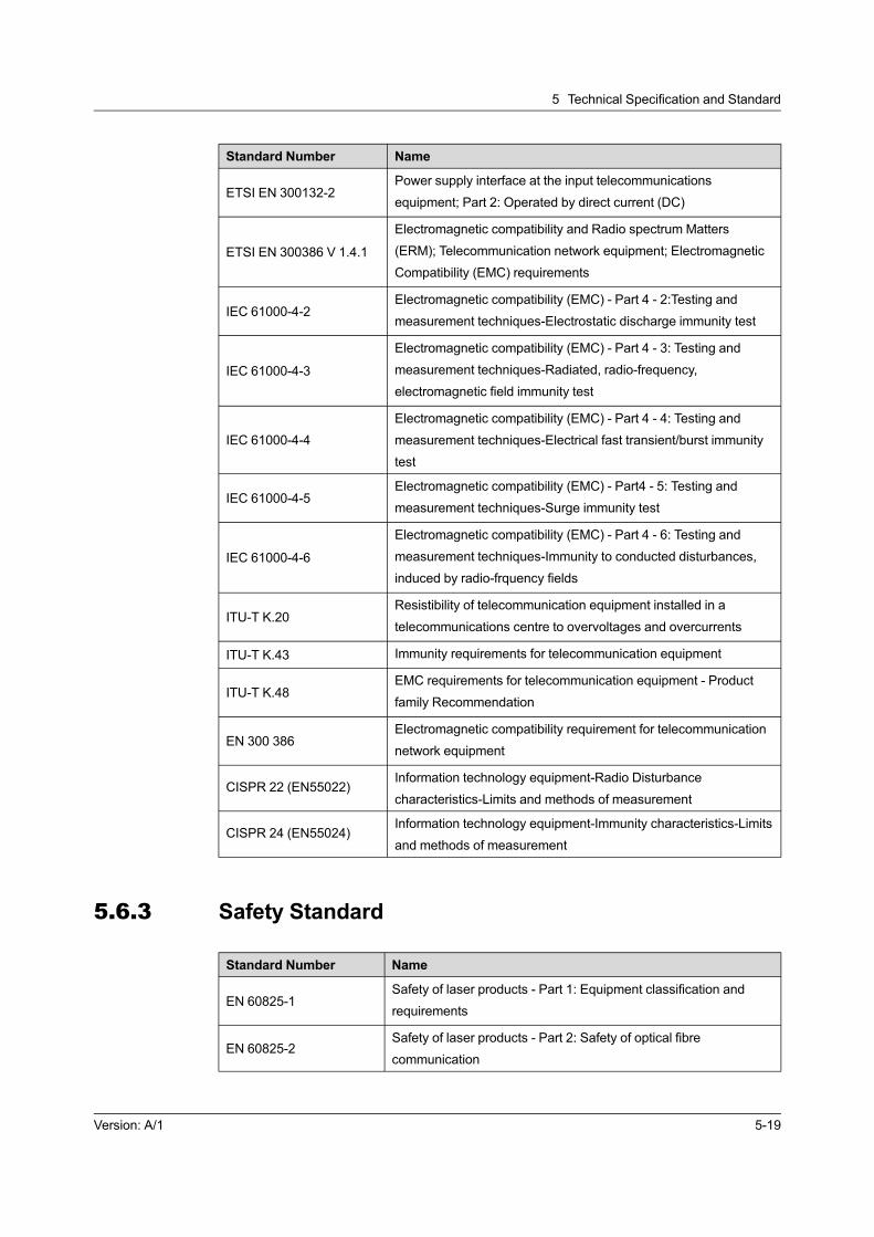
5 Technical Specification and Standard
Standard Number Name
ETSI EN 300132-2Power supply interface at the input telecommunications
equipment; Part 2: Operated by direct current (DC)
ETSI EN 300386 V 1.4.1
Electromagnetic compatibility and Radio spectrum Matters
(ERM); Telecommunication network equipment; Electromagnetic
Compatibility (EMC) requirements
IEC 61000-4-2Electromagnetic compatibility (EMC) - Part 4 - 2:Testing and
measurement techniques-Electrostatic discharge immunity test
IEC 61000-4-3
Electromagnetic compatibility (EMC) - Part 4 - 3: Testing and
measurement techniques-Radiated, radio-frequency,
electromagnetic field immunity test
IEC 61000-4-4
Electromagnetic compatibility (EMC) - Part 4 - 4: Testing and
measurement techniques-Electrical fast transient/burst immunity
test
IEC 61000-4-5Electromagnetic compatibility (EMC) - Part4 - 5: Testing and
measurement techniques-Surge immunity test
IEC 61000-4-6
Electromagnetic compatibility (EMC) - Part 4 - 6: Testing and
measurement techniques-Immunity to conducted disturbances,
induced by radio-frquency fields
ITU-T K.20Resistibility of telecommunication equipment installed in a
telecommunications centre to overvoltages and overcurrents
ITU-T K.43 Immunity requirements for telecommunication equipment
ITU-T K.48EMC requirements for telecommunication equipment - Product
family Recommendation
EN 300 386Electromagnetic compatibility requirement for telecommunication
network equipment
CISPR 22 (EN55022)Information technology equipment-Radio Disturbance
characteristics-Limits and methods of measurement
CISPR 24 (EN55024)Information technology equipment-Immunity characteristics-Limits
and methods of measurement
5.6.3 Safety Standard
Standard Number Name
EN 60825-1Safety of laser products - Part 1: Equipment classification and
requirements
EN 60825-2Safety of laser products - Part 2: Safety of optical fibre
communication
Version: A/1 5-19
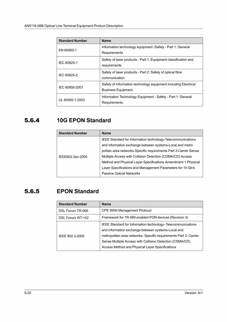
AN5116-06B Optical Line Terminal Equipment Product Description
Standard Number Name
EN 60950-1Information technology equipment -Safety - Part 1: General
Requirements
IEC 60825-1Safety of laser products - Part 1: Equipment classification and
requirements
IEC 60825-2Safety of laser products - Part 2: Safety of optical fibre
communication
IEC 60950-2001Safety of Information technology equipment including Electrical
Business Equipment
UL 60950-1:2003Information Technology Equipment - Safety - Part 1: General
Requirements
5.6.4 10G EPON Standard
Standard Number Name
IEEE802.3av-2009
IEEE Standard for Information technology-Telecommunications
and information exchange between systems-Local and metro
politan area networks-Specific requirements Part 3:Carrier Sense
Multiple Access with Collision Detection (CDMA/CD) Access
Method and Physical Layer Specifications Amendment 1:Physical
Layer Specifications and Management Parameters for 10 Gb/s
Passive Optical Networks
5.6.5 EPON Standard
Standard Number Name
DSL Forum TR-069 CPE WAN Management Protocol
DSL Forum WT-142 Framework for TR-069 enabled PON devices (Revision 3)
IEEE 802.3-2005
IEEE Standard for Information technology–Telecommunications
and information exchange between systems-Local and
metropolitan area networks- Specific requirements Part 3: Carrier
Sense Multiple Access with Collision Detection (CSMA/CD)
Access Method and Physical Layer Specifications
5-20 Version: A/1
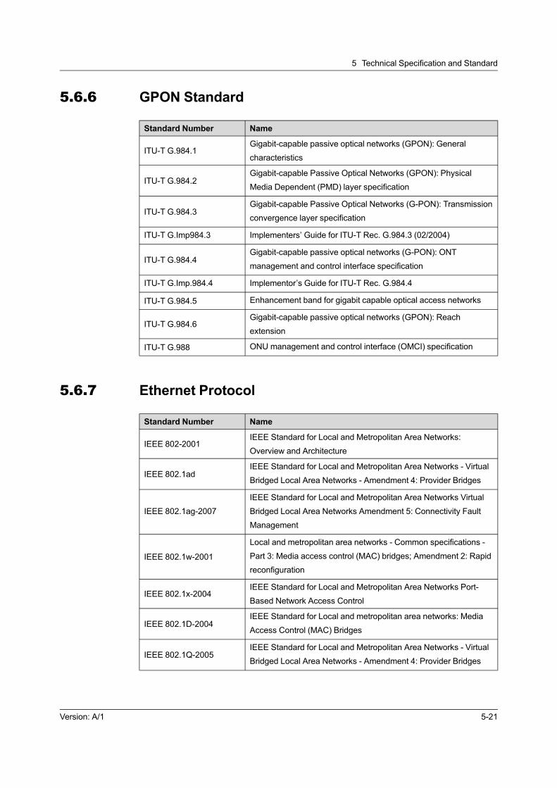
5 Technical Specification and Standard
5.6.6 GPON Standard
Standard Number Name
ITU-T G.984.1Gigabit-capable passive optical networks (GPON): General
characteristics
ITU-T G.984.2Gigabit-capable Passive Optical Networks (GPON): Physical
Media Dependent (PMD) layer specification
ITU-T G.984.3Gigabit-capable Passive Optical Networks (G-PON): Transmission
convergence layer specification
ITU-T G.Imp984.3 Implementers’ Guide for ITU-T Rec. G.984.3 (02/2004)
ITU-T G.984.4Gigabit-capable passive optical networks (G-PON): ONT
management and control interface specification
ITU-T G.Imp.984.4 Implementor’s Guide for ITU-T Rec. G.984.4
ITU-T G.984.5 Enhancement band for gigabit capable optical access networks
ITU-T G.984.6Gigabit-capable passive optical networks (GPON): Reach
extension
ITU-T G.988 ONU management and control interface (OMCI) specification
5.6.7 Ethernet Protocol
Standard Number Name
IEEE 802-2001IEEE Standard for Local and Metropolitan Area Networks:
Overview and Architecture
IEEE 802.1adIEEE Standard for Local and Metropolitan Area Networks - Virtual
Bridged Local Area Networks - Amendment 4: Provider Bridges
IEEE 802.1ag-2007
IEEE Standard for Local and Metropolitan Area Networks Virtual
Bridged Local Area Networks Amendment 5: Connectivity Fault
Management
IEEE 802.1w-2001
Local and metropolitan area networks - Common specifications -
Part 3: Media access control (MAC) bridges; Amendment 2: Rapid
reconfiguration
IEEE 802.1x-2004IEEE Standard for Local and Metropolitan Area Networks Port-
Based Network Access Control
IEEE 802.1D-2004IEEE Standard for Local and metropolitan area networks: Media
Access Control (MAC) Bridges
IEEE 802.1Q-2005IEEE Standard for Local and Metropolitan Area Networks - Virtual
Bridged Local Area Networks - Amendment 4: Provider Bridges
Version: A/1 5-21

AN5116-06B Optical Line Terminal Equipment Product Description
Standard Number Name
IEEE 802.3ah
IEEE Standard for Information technology- Telecommunications
and information exchange between systems- Local and
metropolitan area networks- Specific requirements Part 3: Carrier
Sense Multiple Access with Collision Detection (CSMA/CD)
Access Method and Physical Layer Specifications Amendment:
Media Access Control Parameters, Physical Layers, and
Management Parameters for Subscriber Access Networks
IEEE 802.1s-2002
IEEE Standards for Local and metropolitan area networks - Virtual
Bridged Local Area Networks - Amendment 3: Multiple Spanning
Trees
ITU-T Y.1291An architectural framework for support of Quality of Service in
packet networks
ITU-T Y.1730Requirements for OAM functions in Ethernet-based networks and
Ethernet services
TR-101 Migration to Ethernet-Based DSL Aggregation
5.6.8 Routing Protocol
Standard Number Name
IETF RFC 2362 Protocol Independent Multicast-Sparse Mode
IETF RFC 1723 RIP Version 2 Carrying Additional Information
IETF RFC 2453 RIP Version 2
5.6.9 NGN Protocol
Standard Number Name
IETF RFC 3435 RFC 3435- Media Gateway Control Protocol (MGCP) Version 1.0
ITU-T G.711 Pulse code modulation (PCM) of voice frequencies
ITU-T G.711.1 Wideband embedded extension for G.711 pulse code modulation
ITU-T G.723.1Dual rate speech coder for multimedia communications
transmitting at 5.3 and 6.3 kbit/s
ITU-T G.729Coding of speech at 8 kbit/s using conjugate-structure algebraic-
code-excited linear prediction (CS-ACELP)
ITU-T G.729.1G.729 based Embedded Variable bit-rate coder: An 8-32 kbit/s
scalable wideband coder bitstream interoperable with G.729
ITU-T G.Imp 729Implementers' Guide for G.729 Annexes B, F, G, I and C+ (Coding
of speech at 8 kbit/s using CS-ACELP)
5-22 Version: A/1

5 Technical Specification and Standard
5.6.10 IMS Protocol
Standard Number Name
3GPP TS 23.228 IP Multimedia Subsystem (IMS)
3GPPTS24.228Signaling flows for the IP multimedia call control based on SIP
and SDP
3GPP TS 24.229 IP Multimedia Call Control Protocol based on SIP and SDP
RFC3261 SIP: Session Initiation Protocol
5.6.11 TDM Service Standard
Standard Number Name
IETF RFC3985 (2005) PWE3 Architecture
IETF RFC4197 (2005)Requirements for Edge-to-Edge Emulation of Time Division
Multiplexed (TDM) Circuits over Packet Switching Networks
IETF RFC4553 (2006)Structure-Agnostic Time Division Multiplexing (TDM) over Packet
(SAToP)
ITU-T G.703 Physical/electrical characteristics of hierarchical digital interfaces
ITU-T G.812Timing requirements of slave clocks suitable for use as node clocks
in synchronization networks
ITU-T G.813 Timing characteristics of SDH equipment slave clocks (SEC)
ITU-T G.823The control of jitter and wander within digital networks which are
based on the 2048 kbit/s hierarchy
ITU-T G.824The control of jitter and wander within digital networks which are
based on the 1544 kbit/s hierarchy
ITU-T G.8261 Timing and synchronization aspects in packet networks
TelcordiaGR-1244-
CORE/GR-253Clocks for the Synchronized Network: Common Generic Criteria
5.6.12 Time Standard
Standard Number Name
IEEE 1588-2008IEEE Standard for a Precision Clock Synchronization Protocol for
Networked Measurement and Control Systems
IETF RFC 1305Network Time Protocol (Version 3) Specification, Implementation
and Analysis
IETF RFC 2030Simple Network Time Protocol (SNTP) Version 4 for IPv4, IPv6
and OSI
Version: A/1 5-23

AN5116-06B Optical Line Terminal Equipment Product Description
5.6.13 Other Standard and Protocol
Standard Number Name
IETF RFC 2284 PPP Extensible Authentication Protocol (EAP)
SFF-8472Specification for Diagnostic Monitoring Interface for Optical
Transceivers (Rev 10.3 Dec.1, 2007)
5-24 Version: A/1

Appendix A Abbreviations
ACL Access Control List
ARP Address Resolution Protocol
ARPU Average Revenue Per User
BRAS Broadband Remote Access Server
BSC Base Station Controller
CATV Cable Antenna Television
CDR Call Detail Record
CLI Command Line Interface
CoS Class of Service
DBA Dynamic Bandwidth Allocation
DHCP Dynamic Host Configuration Protocol
DSL Digital Subscriber Line
DSLAM Digital Subscriber Line Access Multiplexer
EMC Electro Magnetic Compatibility
EPON Ethernet Passive Optical Network
FDB Forwarding Database
FEC Forward Error Correction
FoIP Fax over IP
FTTB Fiber To The Building
FTTC Fiber To The Curb
FTTH Fiber To The Home
FTTM Fiber To The Mobile
FTTO Fiber To The Office
FTTV Fiber To The Village
GEM GPON Encapsulation Mode
GPON Gigabit-capable Passive Optical Network
GUI Graphical User Interface
ICMP Internet Control Message Protocol
IGMP Internet Group Management Protocol
IMS IP Multimedia Subsystem
IP Internet Protocol
LAN Local Area Network
MAC Medium Access Control
Version: A/1 A-1

AN5116-06B Optical Line Terminal Equipment Product Description
MGC Media Gateway Controller
MGCP Media Gateway Control Protocol
MoIP Modem over IP
MTBF Mean Time Between Failure
NGN Next Generation Network
OAM Operation, Administration And Maintenance
ODN Optical Distribution Network
OLT Optical Line Termination
ONU Optical Network Unit
OSPF Open Shortest Path First
P2MP Point to Multiple Point
PDH Plesynchronous Digital Hierarchy
PDP Power Distribution Panel
PoE Power over Ethernet
PON Passive Optical Network
POTS Plain Old Telephone Service
ppm parts per million
QoS Quality of Service
RIP Routing Information Protocol
RNC Radio Network Controller
SBA Static Bandwidth Allocation
SCB Single Copy Broadcast
SDH Synchronous Digital Hierarchy
SFP Small Form-factor Pluggable transceiver
SIP Session Initiation Protocol
SNI Service Node Interface
SNMP Simple Network Management Protocol
SP Strict Priority
STB Set Top Box
STM Synchronous Transport Module
TCP Transmission Control Protocol
TDM Time Division Multiplex
TG Trunk Gate Way
ToS Type of Service
UDP User Datagram Protocol
UNI User-Network Interface
A-2 Version: A/1

Appendix A Abbreviations
VDN Video Distribution Network
VLAN Virtual Local Area Network
VoIP Voice over Internet Protocol
WRR Weighted Round Robin
Version: A/1 A-3


Product Documentation Customer Satisfaction Survery
Thank you for reading and using the product documentation provided by FiberHome. Please take a moment to
complete this survey. Your answers will help us to improve the documentation and better suit your needs. Your
responses will be confidential and given serious consideration. The personal information requested is used for
no other purposes than to respond to your feedback.
Name
Phone Number
Email Address
Company
To help us better understand your needs, please focus your answers on a single documentation or a complete
documentation set.
Documentation Name
Code and Version
Usage of the product documentation:
1. How often do you use the documentation?
□ Frequently □ Rarely □ Never □ Other (please specify)
2. When do you use the documentation?
□ in starting up a project □ in installing the product □ in daily maintenance □ in trouble
shooting □ Other (please specify)
3. What is the percentage of the operations on the product for which you can get instruction from the
documentation?
□ 100% □ 80% □ 50% □ 0% □ Other (please specify)
4. Are you satisfied with the promptness with which we update the documentation?
□ Satisfied □ Unsatisfied (your advice)
5.Which documentation form do you prefer?
□ Print edition □ Electronic edition □ Other (please specify)
Quality of the product documentation:
1. Is the information organized and presented clearly?
□ Very □ Somewhat □ Not at all (your advice)
2. How do you like the language style of the documentation?
□ Good □ Normal □ Poor (please specify)
3. Are any contents in the documentation inconsistent with the product?

4. Is the information complete in the documentation?
□ Yes
□ No (Please specify)
5. Are the product working principles and the relevant technologies covered in the documentation sufficient for
you to get known and use the product?
□ Yes
□ No (Please specify)
6. Can you successfully implement a task following the operation steps given in the documentation?
□ Yes (Please give an example)
□ No (Please specify the reason)
7.Which parts of the documentation are you satisfied with?
8.Which parts of the documentation are you unsatisfied with?Why?
9.What is your opinion on the Figures in the documentation?
□ Beautiful □ Unbeautiful (your advice)
□ Practical □ Unpractical (your advice)
10.What is your opinion on the layout of the documentation?
□ Beautiful □ Unbeautiful (your advice)
11. Thinking of the documentations you have ever read offered by other companies, how would you compare
our documentation to them?
Product documentations from other companies:
Satisfied (please specify)
Unsatisfied (please specify)
12. Additional comments about our documentation or suggestions on how we can improve:
Thank you for your assistance. Please fax or send the completed survey to us at the contact information
included in the documentation. If you have any questions or concerns about this survey please email at