Embed Size (px)
Citation preview

Analog Instrument Synthesizer
University Of Central Florida
G e o r g e C o m p t o n
C h r i s S u a r e z
K e n d a l l M u r p h e y
G r o u p # 6
Senior Design Documentation Fall 2012 – Spring 2013

Chris Suarez, Kendall Murphey, George Compton Analog Instrument Synthesizer
1
Table of Contents Chapter 1: Introduction 1.1 – Executive Summary 3 1.2 – Motivation 4 1.3 – Objectives for functionalities 5 1.4 - Objectives for Design 8
Chapter 2: Specifications 2.1 – Input 9 2.2 – Output 11 2.3 – Power 12 2.4 – Housing 12 2.5 – Budget 13
Chapter 3: Functionality Design 3.1 – Overall Design 14 3.2 – Distortion Design 16 3.3 – Square Wave Design 18 3.4 – Rectifier Design 22 3.5 – Triangle Wave Design 24 3.6 – Saw Tooth Wave Design 29 3.7 – Koviak Distortion Design 31 3.8 – Shark Fin Wave Design 33 3.9 – Chopper Design 35 3.10 – Hamonicizer Design 36 3.11 – Octave Booster Design 40 3.12 – Oscillator Design 41 3.13 – Tremolo Design 46 3.14 – Phaser Design 47 3.15 – Variable Delay Design 48 3.16 – Flanger Design 50 3.17 – Chorus Design 51 3.18 – Reverb Design 52 3.19 – Housing Design 53 3.20 – Power Design 56 3.21 – Pedi-ergonomic Design 64 Chapter 4: Construction 4.1 – Parts List 65

Chris Suarez, Kendall Murphey, George Compton Analog Instrument Synthesizer
2
4.2 – Printed Circuit Boards 68 4.3 – Housing 69
Chapter 5: Testing and Usage 5.1 – Survivability 69 5.2 – Robustness 70 5.3 – Stress Testing 71 5.3.1 – Electrical 71 5.3.2 – Mechanical 74
Chapter 6: Conclusion 6.1 – Obstacles overcame 74 6.2 – Ideal vs. Non-Ideal testing 76 6.3 – Final Discussion 78
Appendices: A.1 – Block Diagrams 80 A.2 – Schematics 81 A.3 – Bibliography 86 A.4 – Index 87

Chris Suarez, Kendall Murphey, George Compton Analog Instrument Synthesizer
3
Chapter 1: Introduction 1.1 Executive Summary Music is an interesting phenomenon that has occurred in the evolutions of humans and the way they use their ears to interact with their environment. It first started with singing to use some ones voice to aid in telling a story and to convey emotions. The next evolution in music has been in the use of various percussion instruments such as different types of drums to keep rhythms that could be heard over large distances and enjoyed by more people. Next the use of instruments that could play different notes to stay in different key signatures was used so that they could use the notes to convey an emotion without the use of words was used. This mode of musical implementations has been used up until recently where there has been a new surge of using MIDI samples that can be found on the internet then through different distortions that are available on music production software.
This new type of music has spawned new types of sounds that are no long limited by the abilities of a musician, or their instrument. These type of artist have been doing very well in the Grammy’s the last couple of years, increasing number of record sales, and continue to have more top 40 chart placements.
What if a device could be made that could imitate a lot of these sounds created by these computer programs such as Reason, FL Studios, Appleton or any other production software. This device would have to be able to attach to an instrument and be able to distort the sound enough that it could make the instrument sound like those unique settings used by producers and DJ’s alike however you would still want it to be recognizable as the instrument that you’re playing and not want it to sound like just another computer simulated waveform.
For a device like this to be practical it would have to work with the current methods of implementing distortions for instruments. If people couldn’t just plug and play then this device would be a failure. It would be extremely expensive for someone to already buy a new amplification and sound system just for this device, especially since musicians look at their playing of music not only as a hobby but almost as a lifestyle. Professionally and amateurs alike have spent years to perfect their equipment choices from guitars, to amplifiers, to speakers, even down to the brand of strings they use. Therefore, a device like this to be implemented its functionality with the preexisting technology and implementation methods are a must. Also the device must be designed in a way to be implemented while using your feet, this may sound obvious to some and abstract to others. However, this is one of the most important functionalities of this device because then the device can be implemented while the hands are busy playing the instrument.
What if a device that could implement this could be made? Would it be a popular device? How would this be implemented? There have been recent attempts at a

Chris Suarez, Kendall Murphey, George Compton Analog Instrument Synthesizer
4
device like this so far from companies like Korg, and Boss however they haven’t really come close enough to something functional yet. That shows that these big companies at least believe that if they could make the device there would be a demand for it. I believe that if there was a way to implement this kind of music it would be the first bridge between the electric music subset and the more traditional instrument and band lead version of music.
1.2 Motivation The main motivation for this project is to bridge the gap between the effects produced in electronic music and bring them to realization while using an instrument.
It might seem redundant for a device that can implement what a computer can already do. However the current method of producing these sounds does have a common downfall. The live shows are lack luster in comparison to the thrill of seeing a live band. In a club atmosphere or on an IPod it’s alright to just hit play on a computer to enjoy the music. But if this musician is playing a concert in front of a crowd that had paid money to see an artist it would be unacceptable if they just walked up to their computer and just pushed play on windows media player and that was the concert. This is where this gap needs to be bridged which will end up adding elements to both electronic music and the traditional bands playing instruments.
There is believed to be a demand for this type of device because there have been attempts from companies such as Korg and Boss to implement a device like this. However, they have failed for many reasons. They have either made the device too complicated, too expensive, or something so impractical that would need to be connected to a computer interface, which would defeat the whole purpose of the device using instruments instead of a computer. This is for the live show so it is needed for the technology to do what can be implemented in software. However, at the same time it must not be a device so intrusive that people will play the device not the instrument.
This device must also be adaptive to the current methods of playing instruments in a live show setting. This is also a main downfall of using a laptop and the production software, it isn’t meant to be used in live settings. They are for carefully configuring the signal after it is recorded. So this device needs to just be able to plug-and-play the instrument to it without changing the instrumentalist current set up. This is for price, convenience, and practicality of the device. If it is too expensive then the device will have some of the same problems as the higher end devices that are out there right now and no progress would have been made by this device. There also needs to be the convenience of a portable device and it needs to be practical in a way that it can be implemented while not interfering with the users hands. The hands need to be free so this device will not

Chris Suarez, Kendall Murphey, George Compton Analog Instrument Synthesizer
5
be a hindrance of the ability to play the instrument, another area the laptop software falls short of. The most logical conclusion is to have the feet implement be the catalyst for which distortions are chosen.
1.3 Objectives for Functionality Whenever creating new device thoughts need to be organized as far as what you would like the device to do, and how it will be planned to implement this. Only after this is created then you are able to find the specifications that can be implemented and how to design these specifications. This section is to cover some of the basic specifications that will be implemented by this pedal.
This device will be modeled for an electric guitar, which will be the starting point for all design procedure. This will mean that the device will have to be able to take in the standard inputs from an electric guitar and will have to use the same basic outputs for the guitar to the amplifier and to the speaker systems. This means the device as a whole must have as close to a unity-gain as possible. Otherwise when the device is off the amplitude of the guitar signal will either be too quiet or overpower the device when it is on, which must be avoided. There are guitar effect devices that are called “stomp-boxes” these devices are a class of synthesizer devices that remain off until the user steps on it. These devices are small, portable and relatively inexpensive and our device will be something that can take this “stomp-box” to the next level. These types of devices also are all capable of being run off of batteries and have a common power supply input that is universal. It would be beneficial to use a power supply that can match these other devices for convenience of the instrumentalist that will use this device. These devices have also set the standard for how an instrument effect should work. They will take the instrument through a stereo jack and also have a stereo jack as an output. Then any instrument that uses stereo jacks to transport the signal, which is almost any instrument, can be distorted in this fashion.
Since there are almost endless variations of what the different computer sound modulation software are capable it would be senseless to try and imitate them all. The best way would be to find what those sounds are that they use and break them up into separate blocks that can be layered on to each other and dynamically controlled until the user can find the sound that they like. Below is a list of some of the basic effects that should be implemented in this device for it to produce the desired sound.
First sound needs to be the standard overdrive rock and blues distortion that most people associate with the electric guitar. No effect pedal would ever be complete unless it came complete with an overdriven “distortion” setting. This makes the high notes more pronounced on the instrument, while making the lower notes a little “muddier” sounding. This adds warmth to rhythm guitar riffs while adding brightness to any solos. These effects are also called fuzz because
Chris Suarez, Kendall Murphey, George Compton Analog Instrument Synthesizer
6
they can make the note sound a little fuzzy. This classic sound has been around since the 60’s and is still implemented in every type of guitar led music and if the guitar effect pedal didn’t have this setting no one would ever want it.
Now there have been many distortion pedals made in the past that might seem a little redundant but that will be the only commonality of our pedal versus the ones of the past. Those were just a single distortion ours will do much more. The only purpose of the distortion in our stomp-box is more of an ode to the more traditional pedals and to add familiarity to people that is not comfortable with this pedal yet.
The next few distortions are distortions that will definitely separate this pedal from other mainstream distortions. First we are also going to take in the wave form a guitar which is almost a sine wave and output that as a triangle wave, or a square wave. The triangle wave will give it a much distorted sound when one note is played or when a chord is played that will give a very harsh sound. This will definitely make the pedal sound very unique. Next, will be a square wave modulator that will give this pedal a very extremely distorted sound. When the chords are played the separate notes will be almost indistinguishable to the ear but the root note will be in key and able to be distinguished by the ear.
Next is a distortion that was found online in a guitar forum while researching the topics. The pedal had a very clear but still uniquely overdriven tone. The output wave form was shown on this schematic however it used vacuum tubes and the original schematic was wrong. There was correction to the schematic on another site by the original engineer that built the device but it was in Danish, so it was little help. This distortion was neat so it was thought best to incorporate this design in another fashion in the pedal. Since there is not much information on this it must be implemented in another way than the schematic shown.
Next there are rectifier implementations of the sound waves that when using a positive wave rectifier that would give the pedal more of a buzzing sound and while using a negative rectifier then we attain more of a zooming kind of sound.
Next we will have a circuit inside of the pedal that can add harmonics to the original wave and the output will be a rough sounding distortion that will have be almost like a growling sound.
The next distortions we will have are the saw tooth and inverted saw tooth wave forms. These waves are a must, since people have been messing around with the electronic implementations of creating music they have used the waves. These waves give off eerie sounds that sound like they should be in an alien science fiction movie. They definitely sound out of this world and not out of a guitar.
There is a distortion that was named the “shark fin” wave, this has also been a popular distortion used by DJ’s on their computer. This wave form gets its name by the shape resembling a shark where only its fin is above the surface. This

Chris Suarez, Kendall Murphey, George Compton Analog Instrument Synthesizer
7
wave has a gritty sound that has the crunch of a distortion while still maintaining the ability to interact with other harmonics cleanly. In English you can say that if you just play one note it sounds good, and if you play a chord it still sounds good.
The above wave forms are wave form distortions that only take in a wave and leave it at the same phase and frequency. They only change the shape of the wave and have no periodic effect on pitch, amplitude or phase. The next few wave form modulations are modulations that work a little bit differently.
The first of these is a reverb distortion. This effect is very subtle however sometimes it can make a huge difference in the tone of an instrument. This effect will take the sound a guitar makes and play back a very slight echo right after it. This echoing effect ideally mimics the sound of the instrument played in a small room. This effect actually is sometimes used to clean out some of the dirtier side effects of the distortions.
The next distortion is a chorus effect. This will make any note you’re playing sound like there are 2 guitarists playing in perfect unison. The idea behind this is there is a slight delay right at the threshold of what the human ear is capable of discerning. So it will sound like a regular note is played but there is a small extra variance that gives this sound a little extra flavor. This is another effect that is used to clean out some of the harsher tones cause by distorting the sound wave and can give the guitar a mellower and brighter sound.
Next would be a different class of delays. Another modulation that would be great to implement is if there was a variable delay that could be implemented. This delay would allow the user to set the period in between delays and the amplitude of the next delay. These sound effects are used in more abstract forms of music.
On top of the delays another type of effect that would be ideal to implement would to be a tremolo effect. This effect simulates a guitarist playing a note, then letting the note ring out and shaking the note a little bit. This will give the guitar the sound effect of the note being played coming in and out of audibility.
The next type of distortion we would like to add is a flanger, this works by mixing a varying delayed signal which is usually from less than a millisecond to a few times that. This will make the signal cut out at certain points spread out harmonically along the frequency spectrum. The delay is too short for the human ear to perceive as an echo. Sometimes it makes the guitar sound like a jet engine. However we would like to have a variable resonance control, which adds emphasis by applying internal feedback. This would take the sound to a more subtle effect.
The next type of distortion that would be implemented that is very similar to a flanger is the phaser. This effect works by taking the signal and repeatedly putting it in and out of phase with the original signal, hence the name phaser. This effect plays tricks on the human ear because phase detection is how the ear detects a movement of a sound in relation to the ear. However, the amplitude of

Chris Suarez, Kendall Murphey, George Compton Analog Instrument Synthesizer
8
the noise sounds the same. The ear is less sensitive to the effects of phasing when it comes to low frequencies verse high frequencies. The spectrum of a guitar is all in a range that this won’t affect the pedal much however if one was to use this effect on another instrument such as a bass this effect might not be as pronounced. This effect creates a washy spacy sound that would be a great addition to the pedal.
The last but definitely not least effect that will be implemented doesn’t have a name yet. This effect is the most popular effect right now that is used by DJ’s that has yet to be emulated on an instrument and is also the inspiration of this project as a whole. This is a low frequency oscillation on the frequency spectrum from -20Hz to 20Hz. This will gradually bring the signal from the original frequency to 20Hz faster, then slower. This will slowly oscillate the pitch higher and lower. This gives the instrument a “womp womp” sound that has become a staple of electronic music that has been impossible to imitate until now.
These are the separate types of functionality objectives that would ideally be attained by the construction of this distortion pedal device. There are however these objectives are not enough for the device. There needs to also be strict design criteria as well for an effective pedal design which will be discussed in the next section. Each of these effects and their implementations will be described in greater detail in the functionality section of this report.
1.4 Objectives for Design The above objectives were about how the pedal should sound. Next there needs to be some objectives as far as the overall design.
The first and most important objective is it needs to be durable. The switches need to be able to take continuous stomping without any signs of wearing down or breaking. This means the strength needs to also be in the outer shell so that the attachment areas of the switches aren’t in danger of breaking either. Also the device needs to be durable so that a guitarist traveling on the road can take it and not have to worry about it breaking under normal traveling conditions.
Also since this is modeled after the guitar industry it must comply with the industry standards. The pedal must be able to be battery operated and a wall power supply as well. This will have to be interchangeable with the current types of power inputs.
Since it must be low voltage and durability is a must and obviously the best sound possible then they must be created using analog devices. There are many instrumentalists that would not buy a part that was using sampling and programming so as many devices that can be implemented in the analog world the better.

Chris Suarez, Kendall Murphey, George Compton Analog Instrument Synthesizer
9
This will still leave another question, should the device use vacuum tubes or solid state devices. The tubes create natural harmonics that adds warmth to the sound. However they are fragile, conduct a lot of heat, and are expensive. This was an executive decision to go with the idea of using just solid state devices because the heat can affect the other parts. There are more durable when mounted than a tube would be. They are far less expensive. They also use a lot less power. And they are much more accurate, the vacuum tubes need to be offset and the current operational amplifiers are so accurate that for our purposes there is no need to offset it. The op amps are also much smaller than the vacuum tubes. The vacuum tubes have a limited life time of about 10,000 hours or so. The executive decision was made that the increased sound quality that could be attained by using vacuum tubes was not worth some of the negative side effects that could have been onset by that decision.
The last part of the design specification that must be met is the ability for the device to be implemented while playing the instrument of choice. The most logical solution is for the pedal to be able to switch between distortions with the feet. However some of the distortions and tone modulations that are available with this pedal might have negative consequences if played at the same time. The board must be designed in a way that the distortions that can complement each other can be layered however the series of modulations that have negative consequences are unable to be used at the same time. This is so that not only will the pedal always sound its best but this can also prevent the chance for an accidental misstep to affect the sound in a way that might negatively affect a live concert.
These are some of the basic design specifications that was believed to be necessary to make the pedal as robust and as practical as possible. Also, this device must also be an interchange able with the other interface standards that are already on the market. These specifications will be discussed in more detail in the following design specification section.
Chapter 2: Specifications 2.1 Input This device will mainly be manufactured with the end objective to be that any instrument will be able to just plug and play with this device. The easiest instrument to amplify using electronic circuits is the electric guitar. The waveforms that are fed into the pedal will be very clear waveforms, that are almost a pure sine wave and almost free of noise. There are certain instances where there can be an exception to this rule and that must be dealt with.
To first understand where the noise comes from in an electric guitar one must first understand how the guitar works. The electric guitar is a machine that

Chris Suarez, Kendall Murphey, George Compton Analog Instrument Synthesizer
10
transfers vibrations into a voltage signal. The method that most electric guitar manufactures implement this is without any microphones. Instead they use an array of six ferromagnets, which are wrapped with a copper wire. The metal string moving over the ferromagnet acts as a transducer, which converts the vibrational energy from the string into a signal in the copper coil. This method of creating a signal using the ferromagnetic properties was first implemented in the early 30’s and is still the most common method. These transducers that convert the vibrations of the metal string to a voltage signal are called “pick-ups.” These elements are passive and do not need a supply voltage for them to function properly. This has also been one of the advantages to this type of input versus some of the more modern pre-amplifier circuits that run off of batteries which might run out during a show, worst case scenario. However, these old fashion inputs aren’t without flaws. Since they are constructed out of an exposed metallic material they are especially susceptible to the photoelectric effect. This effect is usually so minuscule most electronic devices can usually ignore this. When looking at the life cycle of the electric guitar it is obvious why this is not the case. When being used in front of an audience the production staff will use very high power lights of many different colors to light up the stage. This will cause noise in the pick-ups. This type of noise creates a small hum that in smaller venue settings can be ignored but on a bigger venue the photoelectric noise can actually drown out the original signal.
The next type of noise that will need to be taken into account when designing this device is a term called feedback in the music industry. This is an instance where the jargon of musicians and the jargon of electronics professionals differ. Anybody with a background in electronics would look at the schematic and say that the whole effect pedal is based off feedback and that’s why it attains the sounds that are desired. However from a musician perspective feedback has a different meaning. For musicians feedback is when the instrument pickups start to pick up the sound of the amplifier. This starts to create an undesired feedback loop that actually increases in pitch and amplitude very quickly. There has been much advancement in the way pick-ups are implemented to prevent this side effect without sacrificing the sound of the instrument. One of them has been to add an extra array of six ferromagnets in parallel to the original and this is there to just offset any noise that might be taken in. These types of pick-ups are called humbuckers and the first type is called dimebuckers. The humbuckers are much less susceptible to the high frequency feed backs and are used in almost any instrument with a range of higher pitches such as a violin. For instruments whose range is on the lower frequencies the dime buckers are used almost extensively because they make the deep sounds a little brighter such as on a bass guitar. The common six stringed electric guitar however falls somewhere in the median of these instruments. Some people prefer the more control they have over the music without feedback, while some people think that the dimebuckers give a better more wild representation of how an electric guitar should sound. Since this pedal is modeled to fit any guitar this must be taken into consideration. There needs to be protocols set to avoid the chance of any negative feedback.

Chris Suarez, Kendall Murphey, George Compton Analog Instrument Synthesizer
11
Also the input is going to match with the industry standard of using a quarter inch mono jack to transmit the signal. This is to allow the pedal to have just a simple “plug-n-play” feel to it. Since almost every instrument uses this sort of cable to carry its signal over short distances this would be the ideal input.
2.2 Output This pedal will have many different output modulations that the pedal can achieve. Each of these modulation outputs will be discussed in more detail Chapter 3, in the design specifications aspect of the pedal. The output must use a quarter inch mono instrument jack. This is the standard for most musical applications involving effect boxes. The input from the instrument will be about one and a half volts peak to peak. Most effects pedals have just one effect that they accomplish, especially for distortion. Then they have a setting to adjust the gain of the output. This adds a lot of control to the musician so that when they feel the need to click on the pedal. This also cranks up the sound of the song, making their music more dynamic. The pedal that is currently being constructed will instead implement many different sound effects. If each of these effects that this pedal is able to model has a variable gain then the whole effect box would be full of knobs. That would be impractical and cumbersome. A better solution was found that if every distortion was made to be at a unity gain, then there could be a gain knob at the very end of the pedal to increase the amplitude of the pedal as a whole to the desired sounds.
Another reason behind this unity gain until the end would be that if a musician that had never used this pedal before set the gain of every effect to its maximum when it reached the output the culmination of all those gains would compound to a very high value. At that point clipping by the operational amplifiers and maybe even damaging to the internal components is a possibility. Also many of the amplifiers and speaker boxes that musicians own are very expensive. The last reputation an instrument effect company would like to earn would be a reputation of blowing musician’s amplifiers or speakers.
The last aspect of the output of this pedal is that ideally this pedal will offer the musician that decides to use it a very wide range of tones through layering effects. Some of the tones are more classic tones that any musician would be comfortable and they would feel at ease with. These tones are more common on some high end products. These types of effects will modulate the sound, pitch, frequency, and other timbres of the guitar, but when they are used it will still keep enough of the guitar sound that it would be apparent to audiences that this sound was produced with a guitar. The next type of distortions and modulations that is available for this effect box is the class of distortions and modulations that will do nothing to preserve the timbres of the original instrumental input signal. These will add an interesting dynamic and essentially turn the instrument into a synthesizer. There is a balance so that the user will be able to choose whichever path they want their input instrument signal to go, relinquishing the power of choice to the hands, or feet of the instrumentalist.

Chris Suarez, Kendall Murphey, George Compton Analog Instrument Synthesizer
12
2.3 Power All together the pedal should require a minimal amount of power. The design of the pedal is to use a DC voltage to power all the components that make up the device. Throughout the design it will be required to power various operational amplifiers, 555 timer ICs, an Arduino Uno board, and the led display for each oscillation design. In order to meet these demands the power system for the pedal will be comprised of two major parts.
The device will have the option to either be battery powered or plugged into a conventional wall outlet. This is so the pedal will have mobility when needed. This will be accomplished through AC to DC conversion as well as DC to DC conversion. A dual rail system will be implemented to give a positive and negative 9 volts for the system. Each component will have its own unique restraints for the power system which will be addresses later in the design section of power.
While using an AC outlet the pedal will be designed to charge the batteries in the DC section. A protective circuit will be designed to protect the batteries from overcharging and exploding as well as allow the battery source to become the prime power source if and when the pedal is unplugged.
2.4 Housing The housing for this device will obviously need to be big enough to house all of the components, without any excessive space. It is likely to be a very large device, as it is housing analog circuitry for several different functions. A typical pedal that is built for one purpose is about 35 cubic inches, which includes the pedal, the knobs, the battery housing, and the actual circuitry. They are relatively compact, and for our purposes each contains redundant features. The device will need enough circuit space for about 16 different effects, but it will only need one main power source, a small amount of pedals (2 or 3), and a fair amount of general purpose knobs. Below in Table # 1 are the housing specifications.

Chris Suarez, Kendall Murphey, George Compton Analog Instrument Synthesizer
13
Generalized specifications:
Size Mid-sized computer tower. 2000-3000 in3 Material Aluminum. Typical housing material of modern pedals Non-slip rubber feet Cooling Power heat sink + 1-2 fans Partitions Power User interface Modulation User Interface 5-10 knobs 2 foot pedals, 1 dual-mode expression pedal LED light array Input 1/4 Mono audio jack Output 1/4 Mono audio jack 1/8 Stereo headphone jack
Table # 1 – Housing Specifications
2.5 Budget Several of the ICs being used to build this device are being obtained for free, through Texas Instrument’s free sample system. There may come a time when these components will need to be purchased, but until then they will not cost anything. The real cost will likely be in the fabrication of the PCBs used in the device. If the PCB were to be made, it could cost maybe $50 a professionally manufactured set of PCBs will be far more expensive, possibly in the $100 - $150 range. Which fabrication method is chosen will simply be dependent on how much time is available to build and test this device. For the sake of the budget table, the most expensive options will be approximated. A total of all foreseeable costs are shown below in the budget summary (table # 2).
Housing $50.00 PCB $150.00 Components $50.00 Custom Pedal $35.00 Tools $50.00 Total $335.00
Table # 2 – Budget summary
About $350 is a decent price point for the entire device. It will likely cost less, but otherwise it should be not a terribly large sum of money to build this.

Chris Suarez, Kendall Murphey, George Compton Analog Instrument Synthesizer
14
Chapter 3: Functionality Design 3.1 Overall Design This section of the design summary is going to go in more detail about every single aspect of the different functionality portion of the circuit designs in the device made. This section will briefly discuss the different designs and their methods of operation. There is this device will have many different design features which will allow the musician to have a lot of power in their hands to implement many different waves that were mainly unable to be attained before now. However there will be many different choices the musician can implement one of the most important design aspects of the pedal is that effects that will have an adverse effect on each other should be implemented in parallel so that there is no way that they can be used at the same time. This will keep the product sounding great when in the hands of a seasoned effects aficionado or a novice and this is his first instrument pedal. Also this will help to ease the learning curve of a first time user so that the first time they use it, they don’t have to even really know what each effect does. They just can’t go wrong while using the pedal. There is reasoning behind this logic of effect implementation, this effect stomp box is created to help implement songs with electronic sounding qualities but in a live setting. If something happens and the wrong effect is accidentally stepped on, which happens every now and then in live concerts, the “show must go on” or so to say. These musicians would have to keep going and improvise with the mistake. This will help take out some human error that might occur when using this pedal, so that at least the effects will be clear and desirable even if they aren’t the way the musician initially wrote the song.
The wide range of effects for this device can be broken up into essentially three types of effects. There are the distortion effects, the wave effects, and the frequency effects. One of each effect type can be used at once, or any two, or any one, or none at all. The order in which the input signal is modified is quite crucial. If distortion were to be done as the last phase, it would be selective in what it decides to clip, distorting only the higher amplitude portions of the oscillator-effect-driven waveform. If it were done as the first phase, then the wave effects would not be representing a true transformation from sinusoidal to the desired wave. The order in which the effects need to be processed sequentially is wave effect, then distortion effect, then frequency effect.
That being said this is the most basic layout that would be necessary to implement this in a predictable and user-friendly fashion.
The first stage will contort the wave shape in order to change it from a natural sinusoid to one of the previously mentioned synthesized wave shapes. This stage is first because the device simply needs an unaltered, pure signal in order to work. As already mentioned, if the distortion stage were to happen prior to this stage, the contorted waveform would not represent an accurate transformation.

Chris Suarez, Kendall Murphey, George Compton Analog Instrument Synthesizer
15
The user can choose to isolate this effect type from the other two if only a pure wave transformation is required for the music. Several distortions that altered the wave form would have to be all in parallel because these effects can’t be layered in a predictable way. And even some of them would null the effect of the other. The first level of distortions that wouldn’t be able to be layered is the distortion design mentioned in section 3.2, the square wave distortion, the saw tooth distortion, the Koviak distortion, the shark fin distortion, and last the Octave Booster design. The first stage will contort the wave shape in order to change it from a natural sinusoid to one of the previously mentioned synthesized wave shapes. This stage is first because the device simply needs an unaltered, pure signal in order to work. As already mentioned, if the distortion stage were to happen prior to this stage, the contorted waveform would not represent an accurate transformation. The user can choose to isolate this effect type from the other two if only a pure wave transformation is required for the music.
Next block that should be implemented would be the harmonicizer, no that is not a misspelling and it will be further discussed in section 3.9 which deals with this effect. This will essentially make the current waveform “dirty” giving it a much fuller, saturated sound. As explained before, the distortion effects are used for achieving a more aggressive tone, and are used widely in that sense. Combining the transformed wave with the distortion effect should produce a hybrid sound of synthesized and organic noise, providing unique musical opportunities. As with the first effect, the option to isolate this stage exists.
The next block will have to be a design that uses the LFO to implement low frequency pitch modulations. This will then be fed into two types of effects in parallel the flanger and the chorus will have to be in parallel. The output of this block will go to the phaser, which will then go to the tremolo. Here there would be another effect that might end up on the box and it would be called the chopper. It would use the 555 timer as a clock with a potentiometer to set the duty cycle. This will switch between the modulations of the LFO and after, then back to the original distorted sound. This device is a work in progress and might not be implemented in the final design, which is why it doesn’t have its own section dedicated to it. Then the last effect that the instrument will be fed through is the reverb which will help clean up the entire sound and make it not sound as muddled. Using this method of design the pedal will be able to account for mistakes on the part of the user, by either lack of knowledge of how each distortion affects the wave form or accidental implementations of undesired effects.
Because each of these stages is capable of being isolated, each one of them will require some form of post-gain control before the signal is sent on to the rest of the device. This will ensure that no matter what combination of effects are used, the output of the waveform stays at a constant desired level.

Chris Suarez, Kendall Murphey, George Compton Analog Instrument Synthesizer
16
3.2 Distortion Design This section is about the distortion design aspect of the pedal. All of the different design aspects in the functionality design that deal with wave form manipulations and modulations are distortions but this type is a term used by instrumentalist as distortion. For the rest of this section we will just refer to this part of the pedal as just “distortion.”
This type of distortion is the type that almost every music aficionado can recognize. This is actually the easiest to implement. This class of sound was first developed by marshal. It was after the band the kinks released their hit song “You Really Got Me.” They had a rough and gritty guitar sound in this song that was never heard of before this song. They achieved this sound by actually taking razor blades to the cones of their Marshall Guitar amplifier speaker boxes and slashing slits in the cones. Once Marshall heard that this is what the kinks were doing to their speakers, Marshall quickly insisted that they would get a new set of marshal amplifiers and a pedal box that would mimic those sounds and they would never need to slash the speakers again. Marshall quickly dialed up their engineers and put them to work to create a pedal that would mimic this sound. The sound engineers were presented with an interesting predicament they had spent their whole careers trying to maximize the clarity of the tones of the guitar. Now, their job was to take a guitar and make it sound more fuzzy and muddled. After research they found that since a guitar signal is very close to a sine wave they could implement a clipping function and when played back in the amplifier it sounded very similar to the gritty, fuzzy sound that the kinks stumble across by slashing their speakers. This gave birth to a new mentality when creating this sound distorting device the engineers at Marshall figured out that they could add a way to control how much of this fuzzy effect was implemented by controlling how clipped the wave actually got. However this added a small predicament the engineers the more the signal was clipped the smaller the amplitude and the new effects were quiet compared to the original signal. The engineers came up with and ingenious decision. They decided that they could put the control in the hands of the player. There would be two separate knobs for the player to control. The player can control the amount of clipping and the amplitude gain afterwards and leave those set preferences that can be left while not in use. This adds a dynamic ability to allow the song to build up and get quieter to emphasize certain parts of the song. This class of pedals has been dubbed as booster pedals, for their ability to make their sounds louder. Other names that have been used to describe these pedals are fuzz pedals for their warm fuzzy sound that they produce. The final and most common name for this type of pedal is just called a distortion pedal.
These pedals pioneered the sound distortion technology they had actually tried its best to make a square wave but at the time they used tube amps to realize this distortion. The problem, which ended up being a positive of the tubes were that they are unable realize a sharp flat edge while clipping a sine wave. This ended up giving the distortion a mellower sound than intended. This also had a

Chris Suarez, Kendall Murphey, George Compton Analog Instrument Synthesizer
17
positive side effect when a perfect square wave signal has harmonics added to the signal, the signal becomes very muddled and it is difficult to separate the different signals. This might seem like a very insignificant issue but this would mean if a single note was played then the note would be easily distinguishable by the human ear, however if more than one note at a time was played in unison the human ear cannot separate the different notes. This can leave a less than pleasant sound for the ear. This was a phenomenon that wasn’t realized until advancement in solid state devices was made.
The advancements in diodes, transistors, and operational amplifiers revolutionized the technology used in guitar pedals. These new devices were much smaller, used less power, had much smaller offset voltages, and didn’t have the problems associate with heat that the older, bulky vacuum tubes created. The sound engineers were now finally able to create an almost perfect square wave. They used the same schematic and modeling methods that were implemented while using a vacuum tube and the clipping methods were almost perfect squares. These new devices did very poorly in the market because of the problems stated above. Most of the guitarist actually stayed loyal to their older vacuum tube pedals and they became a commodity once they were discontinued because of their superior sound quality. The engineers went back to the drawing boards and since the 70’s they have been trying to find a happy medium between the harsh clipping of the diodes, transistors, and operational amplifiers. And the smooth curves of the tube distortions.
This has presented a conundrum when designing the device. The rounded edges sound much cleaner when the device is implemented. However the executive decision was made to use the solid state devices. This might sound illogical however with a short explanation it is easy to see that this was the most logical decision. First, the tubes use so much heat that it would be very difficult to control, the solid state devices when used the way that was implemented in the pedal it would give off a negligible amount of heat. Next the tubes needed to be offset by a high voltage and the solid state devices are so accurate now that the inherent offset is negligible. The amount of power used by the solid state devices is very low in comparison that makes it easy to power using just batteries. The price is also a factor, Texas instruments has been supportive of the senior design process so they have donated TL084 operational amplifiers for the students to use. These are the ideal operational amplifiers to use for this project because of their ease of use, reliability, low power usage, and accuracy. The diodes used were 4148n signal diodes they were superior to a vacuum tube realization because they were also donated to the University of Central Florida, their predictability is very high, and heat dissipation is almost nothing. Also both of these parts are a lot more durable than their vacuum tube counterparts. The durability of the device is definitely a must.
It was difficult to try implementing a method of realizing this softer clipping without the use of tubes. After creative planning the TL084 would amplify the sound tremendously then it would be clipped by the diodes in parallel to a

Chris Suarez, Kendall Murphey, George Compton Analog Instrument Synthesizer
18
capacitor to slow down the clipping and round out the edges. There was a problem when the operational amplifier was amplified very much it created some extra high frequency noise. This was removed by adding a resistor and capacitor to the circuit to act as a low pass filter. This cleaned out the noise. The diode made the amplitude of the signal drop to a point that was unacceptable for our purposes so there was an amplifier added to the output to bring the gain of the circuit as a whole as close to unity as possible. Shown below in figure # 1, is a simulation of the input guitar signal (blue) and the output of the distortion signal (green).
Figure # 1 – Distortion wave
The values of the resistors and capacitors had to be tuned once plugged into the guitar so that it would reach the desired output sound. However the chosen values for resistors and capacitors had led to a great medium between harsh almost square wave clipping and a rounded tubular style of clipping.
3.3 Square Wave Design This next type of distortion is a type of distortions that any synthesizing pedal wouldn’t be complete without. This next design will be the heart of the type of synthesis. This block of the guitar effects device will implement a pure square wave. The reason this is in the pedal is to give the instrument that will have its sound modulated to have a completely digital sound, which might be a desired effect by the musician.
The effect of this will be universal for any instrument that will be modulated using this pedal. This will give a pure square wave. Any instrument modulated through this will be indistinguishable from the other. This will have some of the similar sound qualities of the effect mentioned above with the distortion. However it will also sound like a cleaner, brighter and sharper sound. This sound will not sound muddled when chords are played with it.
Since this wave form will output as near perfect square waves as possible then almost any instrument using this square wave form distortion will sound identical. The distortion above still allowed some of the timbre and natural resonance of the instrument to still pass into the output wave. This circuit will not allow that.

Chris Suarez, Kendall Murphey, George Compton Analog Instrument Synthesizer
19
The timbre is what allows the human ear to distinguish sounds not characterized by pitch (frequency) or loudness (amplitude). If two separate noises have a timbre difference of 12.9 then studies have shown that most human ears can distinguish the difference between the two signals even if they have the same pitch and amplitude. The goal of this section was to create a type of square distortion that was relentless to any timbre and would maintain the square wave pitch and set amplitude no matter the input signal.
This criterion would essentially bring the timbre difference down to zero between different modulated inputs and make this pedal a true synthesizer. There are certain tonal qualities that affect the timbre.
The first tonal quality that affects the timbre is the enveloping. There are two separate types of enveloping. The first is the spectral envelope. This will be unified since all the outputs will be a pure square wave, thus nulling any enveloping effects that might be added by different spectral densities. The next type of enveloping that occurs with musical instruments involves amplitude of a note and how it rings out. How sharp the note reaches its peak amplitude is known as the attack. How long the instrument is able to maintain the peak amplitude of the tone played is known as sustain. The last characteristic of this type of enveloping is how fast the note goes from the peak value to zero which is known at the decay. The combination of these enveloping characteristics will be minimalized by the square wave generator only sending a signal when the wave hits a certain threshold voltage. This way the only difference in the timber of a note will be how long it last which will vary from instrument to instrument but that will not be enough to reach the timbre difference of 12.9 for most instruments. It will just be a time difference in how long the modulator will hold a note which will be the only difference between timbres.
The next main characteristic of the timbre of an instrument, that is independent of volume and pitch, is the resonance of an instrument. The resonance is more of a physical characteristic of the atomic structure of the building materials used in the instrument. Such as the guitar is only made out of certain types of wood because those are the types that have the best natural resonances for the purpose of creating music. The sound waves generated by the strings are then amplified by the natural vibrations of the wood chosen to build the guitar. These resonance frequencies of the atoms are at harmonics that match the notes played and will amplify the sound however if a wood is chosen that doesn’t contain these natural resonances then it might even work to null the sound. These resonance properties of the guitar will give certain types of guitars more value as well as any other type of instrument. The guitar output signal is close to a sine wave however it has small vibrations in the actual sine wave of the guitar and this is related to the resonance and it can’t be taken out using a low pass filter without sacrificing the range of the instrument. These natural resonant frequencies make such a difference in timbre and allow the human ear to distinguish between string instruments, drums, woodwind, and brass instruments with ease.

Chris Suarez, Kendall Murphey, George Compton Analog Instrument Synthesizer
20
This class of square wave distortion will break down those barriers between the instruments and all the instruments modulated with have the same tone, the only difference will be the length that the instrument can hold that tone.
The process of creating a suitable square wave was a more daunting task that initially imagined. Since the guitar output is almost a sine wave it is impossible to create a perfect square wave from it. Below are some of the methods that were experimented with to design a clear output square waveform.
The first thought was, to achieve a simulated square wave the rise time must be extremely fast. In most applications the best way to achieve this is an extremely under-damped system. This under damping gave rise to a large impulse. Which was expected and to get the results wanted it was needed to test on the system on the highest frequency that the guitar would output and work from there. If the system could form a reasonable amount of settling time at 1200 Hz, which is a little bit higher frequency than the highest tone in range of the guitar. Then, the system could settle in enough time for any note along the guitar neck. This system was actually very capable of achieving the predicted outputs using dual Sallen-Key configurations to compile a fourth order system. At first this system seemed like the answer after the simulations in LTSpice gave output waves that seemed desirable. Once in the senior design lab the oscilloscope read the same outputs. The output wave seemed really clean with a fast settling time and had a relatively small max overshoot and a great rise time. When given the last and most important test, the guitar and ear test however it didn’t perform so well. The output wave was actually a great sounding distortion that sounded almost as good as the distortion described in section 3.3, however, this type of distortion was not the desired effect. It allowed the natural timbers of the guitar through. The overshoot actually added a nice flavor to the sound but it was not the desired sound effect. The thought was that adding a low pass filter after the over damp system would help take out some of the added harmonics however this didn’t have the desired effect instead they just took the life and brightness out of the tone and made it sound dull and flat. Clearly this was not an appropriate solution to the problem, so a new solution had to be devised.
The next possible solution was to use an under damp system so that it wouldn’t have any overshoot. The thought was that maybe this would make the wave more like a square because it would have no rippling effect for the settling time. The main problem with using this method to implement a square wave is the slow rise time. The fast rise time but with an undesirable overshoot was traded out for a slow rise time but with no overshoot. The solution to this problem was to just increase the order of the filter. When a 10th order under damped system was implemented the simulations from LTSpice looked as if they were going to work. When built in the lab even though this circuit was almost 3 times as cumbersome as the 4th order system it was believed that as long as it functioned properly that it was worth it. When simulated on the oscilloscope the filter did a great job of taking out any resonances and looked almost like a square wave when simulated on the high ends with just the front corner a little bit rounded but a sharp back

Chris Suarez, Kendall Murphey, George Compton Analog Instrument Synthesizer
21
corner. On the lower frequencies it looked exactly like the desired wave it as impossible to tell that it wasn’t an actual square. However this was another case where the simulations didn’t match the ear. This wave sounded dull and flat as well. On the lower notes it sounded decent, but on the high noted the tone was so lackluster that there was no way that it would ever be implemented in the device.
Then came the thought that maybe this was the wrong way of implementing this output and that damping systems weren’t the proper way of achieving this function. The method of the distortion above involved using a TL084 with a gain so high that the circuit clipped at the rails, cutting off the wave. Then this wave could be clipped by diodes and voltage dividers to make the corners sharper. Last the signal could get amplified again back to the original amplitude so that the system as a whole would be at a unity gain. The only problem with this circuit was the gain wasn’t high enough to give a sharp rise time to create a square looking wave. So the gain was increased by using a one mega ohm resistor as the negative feedback loop with a one kilo ohm resistor as the negative input. The result was an almost perfect square when simulated in LTSpice. However, when taken to the lab and hooked to the oscilloscope the signal was very noisy. This was too much gain for the operational amplifier to make a clear signal. A low pass filter was connected to the circuit in different configurations however the noise couldn’t be taken out without sacrificing the range of the guitar. It was thought maybe the problem is the operational amplifier and not the circuit logic itself. The TL084 was replaced with an OPA270 by Burr-Brown however this amplifier was indeed less noisy, however the noise levels were unacceptable at this range. Since there was an improvement among the operational amplifiers a third amplifier was used the LM351 which actually worked the best but was still too noisy, so it needed a low pass filter as well. There were ranges that the signal was still clean it was worth a try to at least see how it sounded on the guitar to see if this was close to the intended sound. After testing it was concluded that at the ranges that were unaffected by the low pass filter the signal was clean and sounded great on the guitar. This seemed like it was on the right track however not the right method because there was no way of cleaning out the noise without sacrificing the range of the guitar or making it sound flat.
This led to the last method attempted at building this distortion. This idea was that maybe using amplification and clipping as a method for modeling a square wave was the wrong approach to an accurate square. Then the idea to use an LM393 comparator with the power supply as positive and negative power supply and the negative input going to ground, this would make the output a positive nine volts while the signal is positive and a negative nine volts when the signal is negative. This comparator circuit created an almost perfect square wave, with the fastest rise time of all the circuits and the quickest settling time and sharpest edges of the waves. However the amplitude was too high for our purposes so a unity gain buffer using a LM351was attached after the comparator circuit followed by a voltage divider to get the amplitude down to a unity gain for the total circuit. This realization ended up being the most accurate implementation of the square

Chris Suarez, Kendall Murphey, George Compton Analog Instrument Synthesizer
22
wave. This circuit realization also had the smallest amount of parts. When built in the lab this circuit was the easiest to implement and trouble shoot because of the simplicity. Last, all the simulations are great however the most important is the sound test. The desired was a clean and bright sound however this sound was to be completely void of any variations to the sound that add different timbres. This is the most important simulation of a circuit and this was the area that this circuit outperformed all the others by far. Below, in figure # 2, is a LTSpice simulation of the input (green) verse output (blue) of this circuit.
Figure # 2 – Square wave
This is the final output of the square waveform generator that the device would be able to make. Completely free of the original input waveform the only similarities are the pitch and how long the tone is able to be held. Another benefit of implementing this design is that this wave could be used later to help realize more complicated forms of distortions.
3.4 Rectifier Design This next set of distortions will be labeled as the buzz and zoom on the outer casing of the guitar effects box. This is to give the musicians that use this device a more intuitive feel for the box because there are more than a few instrumentalists that will understand what it means to have a rectifying circuit. Not only that this isn’t even a true rectifying circuit so to label it on the pedal board as a rectifier would to be misleading to the instrumentalist that have an electronics back ground.
The reason this must remain clear is in case there is an instrumentalist that had an electronics background that would like to us this device, there can’t be any misleading assumptions made by a name. If they would like to then feed the output signal through another device that would work with a truly rectified circuit then this wave might have an adverse reaction with their circuit or even cause harm to their circuit which must be avoided at all cost for the safety of the user and any devices that they use.
Since the human ear is sensitive to asymmetrical waveforms some distortion pedals in production use this to their advantage. Many of the types of distortions in blues are used have a much mellower sound in comparison to the distortion

Chris Suarez, Kendall Murphey, George Compton Analog Instrument Synthesizer
23
that was constructed in section 3.3, this sound is achieved by an asymmetrical clipping technique. The engineers at Fender and at Gibson will actually take the waveform output from the guitar and clip the negative voltage side of the wave twice as much as the positive side. This gives the wave a closer representation to a sine wave on the positive side of the wave and a harsher, closer to a square waveform on the negative side of the spectrum. Then it is amplified back to unity gain for the pedal on the positive side. However since the negative side was clipped twice as much, the amplitude of the negative side of the wave form is half of the positive side.
This allows the final output to be as clear as a subtle clipping circuit would allow, however it still has some of the harmonic muddling effects that a harsh clipping would allow, but since the muddling is half as audible the total output is fairly clean. That thought was taken that since the ear is sensitive to the actual symmetry of the wave form. Then, how would it sound for a completely asymmetrical wave that resembled no symmetry along the positive x axis.
This was where the idea for some sort of rectifying circuit that still preserved the natural timbre of the input wave form came in. This distortion will have a different effect on which ever instrument is modulated. This circuit was fairly simply made. There are many well studied full wave rectifying circuits for low voltage applications. Which worked perfectly in this application since this device is to work with a positive/negative nine volts as VCC and the input signal will rarely exceed one and a half volts from peak to peak. The design that was finally decided to be implemented contained two 10 kilo ohm resistors, a 20 kilo ohm resistor, a TL084 operational amplifier and two 1n4148 signal diodes. When simulated this circuit worked perfectly and the same for the oscilloscope readings when in the lab. The oscilloscope read outs were as predicted for every frequency and they were consistent for every frequency within the range of the guitar.
There was a problem with this signal, the output was only on the positive end of the x axis, when the circuit was used to modulate the guitar the output was most likely accurate however the ear couldn’t distinguish separate tones when using this form of modulation. When this was realized the first thought was that the reason behind this tone was that for the ear to accurately tell the difference in tones there needed to be a fuller waveform. This meant the wave form would have to be doubled in amplitude then offset by half of the peak voltage, which is how the final wave form was implemented. The positive was called the buzz because that was very similar to the sound made by this circuit. Also if this same circuit was inverted since the positive side of the wave form was pointy and the negative side was rounder this gave the guitar a more zooming sound. This is the origin of the names that will be displayed on the outer housing of the pedal board.
This is one of the areas where switching design is just as important as the effect itself. The switching circuit must be able to be implemented in a way that only one of these effects can be used at a time otherwise this would lead to sound

Chris Suarez, Kendall Murphey, George Compton Analog Instrument Synthesizer
24
issues. Also the option for a full and half wave rectifying would be ideal in addition to the switching between positive and negative. Below, in figure # 3, is the output of the positive rectifier and the half wave right next to it, these will be labeled half and full zoom on the board. The input is green and the output is blue.
Figure # 3 – Rectifier wave
3.5 Triangle Wave Design The triangle waveform is used today in modern music to simulate “retro” music with softer tones than other harsher waveforms, such as the square and sawtooth waves. Triangle waves were used in earlier electronic audio devices as a very simple way to synthesize music and sounds, as it is roughly similar to the sinusoidal waveform (which represents natural sounds) and is easy to produce. The triangle wave features a much softer sound to it than some because of the lack of abrupt signal changes and built-in harmonics featured in some of the other synthesized waveforms, and is suitable at the full range of frequencies. From personal experience, it is very useful at higher frequencies as the necessity of soft tones increases as you increase the pitch of the note. An example of this waveform is shown below in figure # 4.
Figure # 4 – Triangle wave
The steps in logic to produce a triangle wave are relatively simple. First, the natural sinusoid needs to be converted into a square wave. This is explained in the square wave section, but to reiterate; the sinusoid is run through a series of two comparators with a reference voltage at 0V to produce the square wave. The quality of the square wave is important as it is directly related to the quality of the resulting triangle wave. The edges of the square wave need to be as close to a

Chris Suarez, Kendall Murphey, George Compton Analog Instrument Synthesizer
25
ninety degree angle as possible in order to ensure that the points of the triangle wave are as sharp as possible; the sharper the point, the higher the sound fidelity. To produce the triangle from the square, 2 processes are needed. First the square wave needs to be run through an integrator amplifier circuit, which creates the desired set of ramps. Next, the wave needs to be scaled so that its output amplitude matches the relative input amplitude.
The first step is done simply, and only requires a slight modification in order to produce the desired triangle. If the square wave were to be pushed through the integrator with no modification, its output would swing from 0 to twice the max amplitude, which is not desired. The waveform needs to be centered about 0V, so that it swings from negative max amplitude to positive max amplitude. A resistor is placed in parallel with the capacitor across the operational amplifier terminals in order to ensure that the signal remains zeroed. In addition to being off-centered, the wave can occasionally grow exponentially, making it incredibly unstable.
The second step is much trickier. The first step produces a triangle wave that has a fixed slope, regardless of the frequency of the input signal. This is a problem because it will create an inconsistency in the amplitude of the triangle that is dependent on frequency. At lower frequencies, the wave will have a higher cycle time, meaning there is more time for the wave to “build up” and produce a taller ramp. At higher frequencies the opposite is true, as there is very little room between cycles for the ramp to increase. Thus a form of scaling needs to be done to insure that the output voltage matches that of the input.
There are a few designs that are being considered. Two will involve a frequency to voltage converter and an NMOS component. The frequency to voltage converter will produce a voltage that is dependent on the frequency of the input wave, meaning at higher frequencies the output voltage will be greater and vice versa. The NMOS will behave as a voltage controlled resistor, and steps will be taken to make sure that the gate voltage is not high enough to reach saturation levels. Because we want the NMOS to increase its resistance with higher frequencies, we will need to “flip” the gate voltage on the NMOS by using a difference amplifier circuit so that it behaves in its desired way.

Chris Suarez, Kendall Murphey, George Compton Analog Instrument Synthesizer
26
Figure # 5 - Block diagram for first triangle wave design
The first design we have, shown above in figure # 5, uses the NMOS as a gain controller within the integrator amplifier circuit. In addition to a normal resistor that lies in front of the amplifier, there will also be the NMOS that accepts the modified f to V voltage as its gate voltage, opening up and closing its n channel to create less or more resistance, and thus controlling the gain of the circuit. The gain of the circuit is essentially a multiplier, so it will multiply the output circuit by a certain amount to ensure that the voltage never swings too much or too little.
Figure # 6 - Block diagram for second triangle wave design
The second design, shown above in figure # 6, simply breaks up the two processes of making the triangle and scaling it. The triangle is produced with no scaling, and then is run through a voltage divider. The benefit of using this circuit is that the gate voltage no longer has to be flipped as it did in the first design. The voltage divider will use the NMOS as the “top” resistor, and a normal resistor will be the “bottom” resistance. The output voltage will simply be a measure of the voltage of that normal resistor. As frequency increases, so does the gate voltage on the NMOS, resulting in a lower resistance. This means that most of the

Chris Suarez, Kendall Murphey, George Compton Analog Instrument Synthesizer
27
voltage is being dropped across the natural resistor, resulting in a higher net gain of the whole circuit.
A third method that is being considered involves using two NMOS components and a capacitor, all sharing a node. The centered triangle wave is sent through a parallel network of buffers; one is inverted and the other is non-inverted and both have a gain magnitude of one. After bring pushed through the buffers, each branch runs through a comparator circuit with a low Vref of about 0.3V. Then, the resultant waveforms (which should each look similar to a half-wave rectified square wave) are run into the gate terminals of the two NMOS components. The original centered triangle wave will be pushed through the source and drain terminals of the two NMOS components in series, and its constant voltage will be ensured by bypass capacitor that shares the node between the two NMOSs. The entire purpose of this subcircuit is to behave like a frequency controlled resistor; the higher the frequency, the higher the net impedance of the subcircuit. The NMOS subcircuit will behave as the R1 value in a non-inverting amplifier. An increase in R1 will result in a smaller gain, and a decrease in R1 will result in a greater gain. The gain will be scaled just so that the triangle wave will be compensated and it will constantly maintain an amplitude of 1 – 1.2V. An example of the subcircuit is show in figure # 7.
Figure # 7 - NMOS subcircuit design
One issue that was dealt with while simulating this subcircuit involves the square wave signals on the NMOS gates. To keep the circuit cheap, the square wave that was used to create the triangle wave was run through the same aforementioned buffer pair, and then into the NMOS gates, making the NMOS channels alternate; when one NMOS is open, the other is off. Then the first NMOS in the series is turned on, the capacitor attached to the node is charging. When the NMOS channels switch, the capacitor then discharges. The issue that was being experience in the early stages of simulation was the fact that the square waves were overlapping. When the squares overlap both of the NMOS channels are opened up, creating a short from the triangle wave to the opamp. This was fixed by using the previously mentioned comparators. By setting the Vref at a value greater than 0, the time when one square wave switches off is before the time when the other square switches on. This will prevent any overlap and should provide the subcircuit with a somewhat constant value to scale with.
One important thing to consider when attempting to translate from sinusoid to triangle is that the sinusoid may be a composite of several frequencies. The

Chris Suarez, Kendall Murphey, George Compton Analog Instrument Synthesizer
28
guitar is capable of outputting 6 different frequencies at once, one for each string, so we will have to pick one out of the six to be our dominant frequency to use in our f to V converter. The lowest frequency will be chosen, for two reasons.
The first reason is that the wave needs to not be clipped and needs to remain a pure triangle. If the high frequencies were to be chosen as the dominant frequency, the lower frequency signals would continue to ramp up beyond the desired output voltage and would eventually get clipped off, producing a wave that is, simply put, not a triangle. If the lowest frequency is chosen, then the worst that will happen is that the higher frequency notes will simply go unheard because of the strong dominance of the lower frequencies. It will, however, still remain a composite triangle wave.
The second reason is because of musical reasons. If more than one note is being played on the guitar, then the player is intending to play a chord (technically, at least three notes are required to be a chord but it is common in the guitar world to call a pair of notes a chord). With every chord, there is a root note that designates the key of the chord. This root note is almost always the lowest note of the chord, and is essentially the dominant note of the bunch. In addition, the style of music that this device is intended for is not known for using chords frequently and thus will not require that every note be appreciated within a chord. Certainly it would be nice to have a fully robust triangle wave converter, but it would be far too costly, and would have little use in this device. So the lowest frequency will be chosen to go through the f to V converter in order to control the ramping speed of the triangle waves, and a consistent output will be created so that the player need not worry about the amount of attack needed for each range of notes.
The exact method on how frequency dependent voltage will be produced is still being designed. There are a few parts that can do this, and they are being considered for the job. The first one being considered is the LM2907, which is a strict frequency to voltage converter. For this devices application, it would require a fair amount of extra components in order to obtain what is necessary. The output of the component however is exactly what is necessary to power the NMOS in order to have a voltage controlled resistor. Another method being considered is the Baxandall tone control circuit. Instead of using a component to produce a frequency dependent voltage that is then run into an NMOS, the Baxandall circuit can be used by itself as a way of adjusting the net gain of the triangle wave converter. This circuit could potentially cut a lot of cost out of the triangle wave circuit and could be used in several other places within the device. Further research and testing will be needed to asses if this is a reliable circuit, but it would be the most desirable option if it does work.

Chris Suarez, Kendall Murphey, George Compton Analog Instrument Synthesizer
29
3.6 Saw-tooth Wave Design The saw-tooth or saw wave is seen as a happy medium between the triangle wave and the square wave, exhibiting qualities of both. It has the smooth ramp of the triangle, followed by the abrupt shift of the square, making the signal sound smooth and dirty at the same time. The saw is very commonly used in modern music, creating a somewhat aggressive tone for similarly styled music.
Figure # 8 - Saw-tooth wave
The primary way for a saw wave to be generated from scratch is using a capacitor charge/discharge method. The capacitor is charged over a relatively long period of time, and then is shorted out as to empty the capacitor very quickly. This method, however, is not applicable to the devices needs because it needs to be able to convert a sine wave into a saw and have its frequency adjusted as such. An example of this waveform is shown above in figure # 8. So a new design is to be created in order to translate from sine to saw. There are currently 3 designs being considered.
The first design, shown in figure # 9, requires both the square wave and the un-centered triangle wave as inputs, both of them in phase with each other. First a desired slope is chosen, in this case a positive one. Then every negative slope on the triangle wave is inverted so that it has a positive slope, and is then allowed a DC boost so that the original ramp is made continuous. Then the whole wave is centered about 0V and scaled down, similar to how it was done with the triangle wave. The square wave is used to help determine when the slope of the triangle is positive or negative without having to recalculate it using differential amplifiers. When the square wave is at its positive value, the triangle wave is allowed to pass through as it normally does. When the square wave is negative, the ramp is inverted and then shifted to prevent the wave from being discontinuous.
This method is not likely to be used as it is overly complex. It requires a DC shift, meaning that there will be circuitry required to dictate just how much DC to offset it by. After the first shift, a second one will be required after the wave is constructed in order to center the wave about 0V.

Chris Suarez, Kendall Murphey, George Compton Analog Instrument Synthesizer
30
Figure # 9 - Block diagram for first saw-tooth circuit.
The second design uses a similar method as the first, in that it uses both the square and triangle waves to drive it. In this circuit, however, the negative slope will be used. When the un-centered triangle wave is formed, it is formed on the positive side swinging from 0V to twice the maximum positive voltage. So when the voltage slope on the triangle is positive (and thus, the square wave amplitude is positive), the portion of the wave will be flipped about the time axis by simply using an inverter circuit. The result is a centered saw wave, with its magnitude dependent on the input frequency. Similar methods used in the triangle wave converter will be needed in order to scale the wave back down to its desired output levels.
This design is the most likely to be used. It may require some digital logic controllers, but the signal will remain analog. It should be fairly cheap and straightforward to fabricate and test.

Chris Suarez, Kendall Murphey, George Compton Analog Instrument Synthesizer
31
Figure # 10 - Block diagram for second saw-tooth circuit
The third design, given above in figure # 10, uses the original method of generating a saw from scratch, by using a charge/discharge design. The slope of the saw would be dictated by the value of the capacitor used, so a voltage divider would be needed to control the net gain (and thus, slope) of the overall converter. This design will accept only the square wave in order to produce the saw. The square wave will be driving an edge trigger which is what will be telling the capacitor to discharge, and a low power operational amplifier will be controlling the saw so that it does not reach too high a voltage while not in use. The capacitor will be charging at all times so that it is constantly ramping up in voltage, and the positive edge of the square will trigger the discharge of that capacitor. The output of the converter will be the voltage across the capacitor.
This design is likely to not be used, as it is potentially unstable and could cause excessive heat at very low frequencies (below audible range or DC).
3.7 Koviak Distortion Design This next distortion is a little bit more abstract than the others mentioned before. Most of these signal modifications are, at least conceptually, straightforward and easy to visualize what their final intention should be.
This sound was actually found during the research process. There was a Danish man that claimed his friend that is an electrical engineer made him a custom guitar distortion pedal. There were YouTube posts of him playing on this unique

Chris Suarez, Kendall Murphey, George Compton Analog Instrument Synthesizer
32
pedal. The sound was impressive, had the fuzziness of a standard distortion however when a chord was played the harmonic interference that usually muddles the sound wasn’t there on this effect. Each note was clear and easily distinguishable. This pedal was truly innovative. After more research a schematic of the pedal was able to be uncovered. This was a great breakthrough with the research because it would be amazing to put this distortion effect in the hands of the instrumentalist that were using the final product of this senior design project. The ability to reproduce a similar sound was certainly a lustrous goal for any instrumentalist that wanted the benefits of the overdriven distortion with just a little bit more clarity when using harmonic tones in unison.
It seemed that maybe just using that same schematic would have been the ideal method of creating this pedal. However, this wasn’t the case. The design was unpatented which meant that we were free to use it, this was a benefit. However the engineer who’s this distortion was his brain child, was an instrumentalist purist. The meaning behind that statement was that this man believed that music effects should be implemented with vacuum tubes, on the schematic there was even a note stating “REAL ENGINEERS USE TUBES.” This created a problem since there was to be no tubes in the device being built for safety reasons, cost, heat, and power supply problems. However, even if there are no tubes in the current design being built, the old schematic could at least be used as a guideline for the logic of the new design that will be implemented in the effects box under construction. Oscilloscope readout of the input versus output was attained after some more research on this topic. The oscilloscope readout didn’t match the output of the schematic once simulated using LTSpice. It was later found out that the original schematic had a few problems with it and there was a supplemental page explaining the issues with the schematic and how to fix them. This was an aggravation because the supplemental page on how to fix the schematic was all in Danish.
Since engineers are not linguist the executive decision was made to just try and match the output wave form using a guitar as the input wave and seeing where it could be taken from there. Below, in figure # 11, is a picture of the output wave in blue versus the input wave in green over time.
Figure # 11 – Koviak wave
This at first seemed like an extremely daunting task, but after further examination of the output it is easy to see that there were three main components to this wave. First there was a half wave positive rectified wave, a negative positive

Chris Suarez, Kendall Murphey, George Compton Analog Instrument Synthesizer
33
rectified wave, and a square wave at the amplitude of the input wave. This was starting to seem like a much more manageable task one the wave form was broken down to its key components. First the wave would go through 2 separate rectifiers in parallel. One rectifier would be for the positive half wave part of the input and the other one for the negative half wave portion of the input wave. The next part of this wave form would also be in parallel with the input and this would use an inverted square wave. This method of creating a square wave differed from the method used in section 3.3, using the LM393 created a small delay that affected the wave characteristics in an unpredictable way. The method of creating this square wave was to just put two clipping operations amplifiers in series using TL084, and then amplifying the wave back to the original amplitude. All three of these different modulations of the input wave form were then inputted in a summing amplifier. The amplification of this amplifier was twice as much for the rectified parts of the input as the square wave. This ensured that there would be a consistent peak to peak voltage. This was able to create an almost perfect LTSpice oscilloscope output. Once taken to the design lab there was an issue with the size of resistors being used to control gain, these numbers had to be tuned to make the breadboard and oscilloscope outputs match the simulations from LTSpice. Once these testing procedures were complete, it was time for the sound test which this actually preformed much better than expected. This distortion would definitely be a coveted distortion for any instrumentalist using this pedal. This was also named the Koviak in honor of David Koviak, the Danish engineer that originally came up with the idea for this effect.
3.8 Shark Fin Wave Design This next effect is a wave form that is familiar to almost anybody that has had any electronics background. This signal was called the shark fin wave because it resembles the shape of the fin of a shark when it is just above the water’s edge. Almost anybody that has taken electronics class would be able to tell you that wave form would resemble the charge and discharge of a capacitor when the voltage is measured across it.
There might be a question about the motivation for making this effect. This is a synthesis of a guitar that definitely hasn’t been dabbled into and would destroy the original timbres of the instrument that is inputted into the circuit. The answer might be surprising for the motivation.
There was a song by the DJ Skrillex, named “Scary Monsters and Nice Sprites,” which won a Grammy and the album with the same name won another Grammy. In this song there are tones modulated those were very unusual and unique. Some people hated this really harsh very synthetic tone modulation that was done using computer software, but apparently enough people liked it to earn him a Grammy.

Chris Suarez, Kendall Murphey, George Compton Analog Instrument Synthesizer
34
During the research of this device this was a tone that seemed like a great starting point to bridge the gap between the more pure guitar distortions that everyone knows and has come to appreciate and the new digital sounds that were being implemented with these different songs. However, just listening to a sound it is impossible to guess what the output wave form is. So during the research part of the pedal construction there were tutorials of how to create these tones using FL Studios 10. This was extremely convenient because FL Studios 10 also had a built in oscilloscope. After following this tutorial it was discovered that these unique tones that we definitely not from any instrument in the midi catalog they were in fact in the shape of this shark fin wave design.
Now that the waveform was discovered the next part was to figure out how to implement this. Using a resistor and capacitor logic circuit with just the input over the resistor and the output voltage measured across the capacitor to ground. This circuit would work great, at one frequency and not really at any of the high frequencies and the low frequencies will have added harmonics. This is certainly not an acceptable approach to this problem.
After looking at the failed attempt above it was speculated that maybe this was the wrong way to implement a design like this. The next idea was to maybe change the input waveform to a square wave and use an under damped system that would reach steady state right as half the frequency was complete to make this modulated shark fin shape. This method was much more accurate than the method mentioned above. This would give out the wave form that was desired over a wider range of frequencies than the method implemented before. However this method still wasn’t perfect either.
This method had some fatal flaws. This design wasn’t completely consistent throughout the whole range of frequencies that the guitar can offer. In the middle frequencies it produced the desired output but on the low ends it sounded just like a square wave. When the distortion was treated with high frequencies it was even worse than the low frequencies. These would act almost like a triangle wave but it also had a loss of amplitude. Since the circuit used to implement this was a second order Sallen-Key layout with the resistors and capacitors being the same it was possible to create a bump in the upper frequencies to combat this lack of amplitude. This was achieved by altering the quality factor, and the gain on the positive feedback loop. Since the gain was altered another operational amplifier circuit was put in series after the Sallen-Key to bring the total circuit back to unity. This fixed the amplified part of the circuit’s short comings however it didn’t fix the inconsistencies along the frequency spectrum of the guitar. After many headaches it was obvious that this circuit would never be the circuit that could be used to implement this waveform.
At first it seemed impossible to create this wave in a consistent manor across every frequency in the range of the guitar. Then the idea came that maybe instead of using dampening or the charge of components a brute force method could be used to implement this circuit. The thought was that the digital square wave implemented earlier would be perfect for this design to use as a timer then

Chris Suarez, Kendall Murphey, George Compton Analog Instrument Synthesizer
35
the sine wave could be rectified into the positive and negative spectrum of the voltage and ran in parallel. Then there could be a peak voltage detector that would measure the upward slope while the timer from the square wave is at positive voltages then stay at the peak voltage until the square wave goes negative and then uses that same method for the negative side of the guitar signal waveform. This was able to give a consistent method across all frequencies of the output wave all across the neck of the guitar. Also this allowed some of the natural timbre of the guitar to be preserved on the rise time of the peak detector but then had a very digital sound for the second quarter of the sound wave. This was by far the most superior method of constructing this wave because it was so consistent throughout every frequency in such a predicable manner. Also it maintained the original decaying envelope of each note played by the guitar. This was the perfect balance between a true guitar effect and a modulated synthesized sound. Below is an input versus output of this waveform. The simulation below shows the output in green and the output in blue.
Figure # 12 – Shark fin wave
3.9 Chopper Design The chopper effect is essentially the same as the tremolo, except that instead of using a sinusoidal wave we use a square wave to modulate the signal. The tremolo will produce a much smoother transition while the chopper will have a much choppier sound to it, making the original signal cut in and out sharply. This is not a widely used effect for most modern music, and at best will be used in short bursts to accent certain parts of a riff.
Figure # 13 - Chopper effect

Chris Suarez, Kendall Murphey, George Compton Analog Instrument Synthesizer
36
The design for the chopper is simple as it just uses a standard 555 timer circuit. It differs because one of the resistors is replaced with a potentiometer driven by the expression pedal to control the frequency, without affecting duty cycle. The resulting square wave is then added to the input signal using a summing amplifier, which is then half-wave rectified. The original output of the 555 circuit has also been half wave rectified, but with the opposite polarity. This resulting half-wave is added to the already rectified and shifted input using another summing amplifier, forcing the resulting wave to center itself about 0V. The resulting waveform is the original input, except that it is periodically silenced, forming that choppy sound as expected.
As with the tremolo circuitry, special care is needed to ensure that the larger waveforms of the 555 circuit do not have frequencies that cross into the normal frequency spectrum for the guitar. If it were to be too high, it could end up being the dominant frequency in the waveform and thus dominating the sound with its frequency. The only thing that should be controlling pitch within the device is the guitar and the oscillator, not any of the tremolos. As with the tremolo effect, the user will have access to a knob for controlling the depth. If a user didn’t want to have the signal completely cut out, the depth knob could be turned low.
3.10 Harmonicizer Design When looking at the title of this waveform distortion the reader at first might think that the name is a misspelling. This is the correct way to spell this waveform alteration.
This wave form alteration was another brain child of using the FL Studios 10 to mimic a sound that was implemented in a song. This was actually a more complicated process than the process implemented to achieve the shark fin wave. This distortion would be able to be implemented with any of the other waveform distortions but would have to be implemented before the echoing and phasing effects otherwise it wouldn’t be a clean. The ideal location of this circuit on the path of the signal wave form would be for this to be right after the parallel wave form shaping distortions.
The idea to use this tone was from listening to a song named “Stay Crunchy,” by the artist Ronald Jenkees. This song had a smooth synth tone however there was some sort of effect that was added to the sound to manipulate it in a way that would give it a little bit of a “crunchier” sound, hence the name of the song. This effect however didn’t affect the enveloping of the notes fed into the synth. After some brief research it was found that the tone was modulated using computer software to add harmonics to the original sound. Then, all that had to be done was to find a tutorial online on how this sound was modulated to create these tones. Unfortunately, there was no such tutorial. Well if there wasn’t a

Chris Suarez, Kendall Murphey, George Compton Analog Instrument Synthesizer
37
tutorial, then maybe it was possible to find a way to play the song in a way that it could be read in an oscilloscope. Since FL Studios 10 had a built in oscilloscope it seemed like the most logical method of implementing this goal was to download the song. Then once ownership of the song was attained, FL Studios 10 has a function that would let the user splice a recording. The recording was played until a long and clear note was played using the desired tone. Then the song would be spliced and saved as another file. This new tone file would be sent through a “looper” which is a device that will repeat the input until noted otherwise. This “looper” function was instrumental in the ability to hold the tone long enough for the oscilloscope inside of FL Studios 10 to attain a clear read out. This process was repeated a few times to make sure accuracy for multiple notes and multiple frequencies to find what this modulation effect was doing to the output waveform.
When looked at through an oscilloscope it was found that the wave form actually had a harmonic frequency added to the wave. This added frequency was ten times the frequency of the original signal. This added harmonic worked similar to a amplitude modulation circuit but on a very low frequency, and was only one sided, when most amplitude modulation circuits work as a double sided modulation. This modulation would take the input sine signal and take it from its original amplitude down to ground. This was different from other types of amplitude modulations that have an almost symmetric look about the x-axis.
This modulation was different from any of the other distortions that have been implemented so far. The main difference trying to design this circuit and trying to implement the other circuits this circuit will have to make a modulation based on the input frequency of the guitar. This is the first time that a modulation has had to change its modulation based on the frequency of the circuit. This added new a new dynamic to the design process.
The first step of the design was to figure out the block diagram of what this section of the synthesizer would do. Then, the design of each block with actual circuitry would be the ideal method of breaking this design apart to make it seem less daunting. The first block would double the frequency. The second block would then double the frequency again. The third block will take the doubled frequency and put it through a half wave rectifier. The last block will take the original signal and multiply this signal with the rectified signal. This will give the waveform the harmonic drops that were hoping to be achieved.
The first and second blocks are the same. So they can naturally use the same design. This block ended up having some difficulties as discussed below.
At first it was attempted to use log and antilog logic to implement a multiplying circuit. This design uses a resistor on the input terminal and a diode on the negative feedback loop of an operational amplifier. Two of those circuits would be connected in parallel, then after that they would go through a summing amplifier. Since multiplication of numerals is the same as addition of logs this should be equivalent. Then there is an antilog circuit design following the

Chris Suarez, Kendall Murphey, George Compton Analog Instrument Synthesizer
38
summing amplifier. This antilog Design is a diode on the input terminal followed by a resistor on the negative feedback loop. This circuit worked in the simulation as a circuit that would double the frequency. When this design was tested in the lab this circuit didn’t work properly, this was most likely due to the sensitivity of the diodes to heat.
If heat was a problem, then maybe an integrated circuit package could be purchased. There are packages that have built in heat offsets. The model that was decided to use was the MPY634 by Texas Instruments. This multiplier is made to be a wide bandwidth, high accuracy, low noise signal multiplier. This multiplier was intended to be simple to use and even came with a schematic to double the frequency in the datasheet. This seemed like the perfect part to use. However there was a problem this device worked great on the higher ranges but it wasn’t intended to be used at low frequencies. So at about five hundred hertz and below the amplitude would drop down by about a factor of 20. This was a user error that could have been avoided by carefully reading the datasheet.
The next method of trying to implement this design was to use the NA555 timer to create a triangle wave at about 20 Kilo Hertz. Then feed this into the positive terminal of an operational amplifier and have the input from the guitar on the negative input of the operational amplifier the output of this operational amplifier was then fed into a circuit containing a P-channel MOSFET and an N-channel MOSFET. This circuit made a pulse width modulator. Pulse width modulated signal could then be multiplied with itself using a very complicated circuit then that multiplication could then be transformed back into the original signal. The benefit of this design was that the first and second blocks could be implemented in the same step however this circuit was very large and complicated. Then the waveform would need to then be demodulated. Then the output was large and was needed to be toned back down to the original amplitude of the input. This seemed like it was a very complicated method to implement this feature. The results however were very accurate and definitely acted in a very predicable method. After the demodulation a low pass filter was added to make the wave even cleaner. This circuit gave great results but due to the complexity of this circuit it was thought that it would be best to not implement this method unless there was no other option.
Also with the pulse width modulator circuit design some of the parts might be able to be cut out with the use of a pulse width modulator IC. A few of pulse width modulators that were made by Texas Instrument were attained. These are the UC2843AN model of a current controlled pulse width modulator. In the lab these modulator circuits weren’t shown to work in the way that was understood by the datasheet. This might just be a misunderstanding of the datasheet and how to properly implement these products. Also the circuits shown with the datasheet are pretty large. Also the error caused the circuit realization was due to using a 555 timer in Astable-Operational form. A duty cycle of 50% was needed to generate a pure triangle wave however the duty cycle attained was closer to 53% which is still really close however this led to small amplitude difference that was

Chris Suarez, Kendall Murphey, George Compton Analog Instrument Synthesizer
39
still needed to be accounted for when preforming mathematical operations on the pulse width modulation.
Another use of the 555 timer integrated circuit is that it is possible to use this device as a pulse width modulator. This is implemented by using a signal with a DC offset in the trigger. Pin one is connected to ground. Pin number three is the output. Pin four is connected to the positive terminal of the nine volt battery. Pin eight is connected to the positive terminal of the nine volt battery. Pin seven is connected in series between the positive terminal of the power supply, a resistor, and pin number five is connected in parallel to pin six. Which is then in series with a capacitor that is grounded. This design implementation gives a pulse modulated signal that has a small DC offset that is later taken into account and offset. This schematic gives the most accurate duty cycle but it has a more complicated multiplication function. Either way it’s the accuracy in the duty cycle that is scarified or the complexity in the mathematical formulas.
There was maybe an easier way to implement this circuit than using the pulse width modulation technique described. There is another multiplier integrated circuit that is built by Analog Devices it is the AD633. It should work in the range from 10 hertz to 1 Mega Hertz. This device is even simpler in design than the MPY634 from Texas instruments. This part has been ordered but has not arrived yet. It is tough to say if it will perform the way that would be needed for this circuit. This has worked on the simulator however sometimes that isn’t always the case.
The third block in this effect would be to implement a rectifying circuit on the now quadrupled frequency. This would then bring the frequency up to eight times the original speed of the input waveform from the guitar. This would be implemented using resistors, diodes, and operational amplifiers such as described before to implement a full wave positive rectifier.
Then the last block would have to take the original wave form and multiply it by the rectified wave that has eight times the frequency. This section will be implemented using whichever multiplication method ends up being decided as the best, either the pulse width modulation multiplying circuit, or hopefully by the AD633 if it works in a reliable way across every frequency that our circuit should be capable of implementing.
The original sound had a harmonic added to it that was ten times the frequency of the original wave. Ours had a harmonic frequency that was only eight times the original wave but the final output sounded so much like the original wave that it was thought that the difference between the harmonics was negligible. The output wave had a very crunchy sound that still kept the original enveloping of the input guitar wave. This effect succeeded in that aspect of the sound modulation. This effect will be a great addition to the pedal and it will be interesting to see how it interacts with some of the other waveforms such as the saw tooth and triangle waves. This should give it a very screechy, and growling

Chris Suarez, Kendall Murphey, George Compton Analog Instrument Synthesizer
40
sound respectively. This is based off simulations that have been done in FL Studios 10.
3.11 Octave Booster Design One of the main aspects of electronic music is the use of the deep synthesized bass to really add a much more dynamic feel to the song. It is obvious why for anybody that has ever been to a live concert or taken a ride in a car that has a nice bass audio system. When played at very large amplitudes these sounds have a tendency to resonate with every object around and it takes the music to not only an auditory sensation but a tactile sensation as well.
This pedal was designed so that any instrument input would be able to use this analog synthesizer, but the main focus was for it to be utilized by the guitar. If it is only implemented by the guitar then there would be no way for the natural range of the guitar to hit the lower frequencies that a bass guitar can. Well it was thought wouldn’t it be nice if this instrument effect could take in the input of a guitar and with just the push of a button, or a tap of a toe, change the tone to that of a bass. The instrumentalist armed with this device could be a one man band.
After some research it was found that bass music is written in the bass cleft position of the musical spectrum. While the guitar is written on the treble cleft. There are seven major notes in a scale A, B, C, D, E, F, and G. These notes compose the lines and free spaces between the notes. Guitar when written in music is actually written two full scales higher than the actual tone of the guitar relative to middle C, which is the standard for all music theory and it’s at about 440 hertz. This means that the guitar sheet music is written two scales higher than the music is actually intended to sound. This is done just for ease of reading. When looking at the lowest note, which is low E on a guitar it is about four scales higher than the lowest note that the bass can reach on the bass cleft. This being said, simple subtraction can lead to the deduction that the bass guitar has the same notes just two major scales apart. Now to relate that in a discrete value that could be used in this circuit. Well two notes that are eight major notes apart are called an octave. These are actually given the same name because the scale has only seven notes. This eighth note would be given the same note just they are an octave apart. The term octave is the same in music theory as it is in signal processing. An octave is when the frequency is doubled or cut in half, for higher octaves or lower octaves respectively. If that is the case then to make a note on guitar sound the same as it would in the same position the frequency would have to be cut in half for each octave drop. Thus the output would have to be one quarter the frequency of the original signal.
Since these sorts of sounds have no interest in preserving the natural timbre of the guitar there is no need to preserve the signal, pitch is the only concern with this distortion in the analog synthesizer. Actually the more synthesized sound the

Chris Suarez, Kendall Murphey, George Compton Analog Instrument Synthesizer
41
more ideal in this aspect. This style of circuit design added some peculiar design conflicts that had to be overcome and they are described below.
The first way that was thought to implement this method was to use a voltage peak detector then to use a toggle that would follow the next side of the sine wave. This would be similar to the Shark fin realization except it would hold the tone until it got to the next peak. This was implemented with a clock timer and peak detectors. This circuit ended up being much better in theory than in practice. The tone might have sounded good if it was able to be implemented in a predictable manor however it was so wildly inaccurate that this method couldn’t be accurately implements. When it worked it sounded like a bass tone than had a very subtle overdrive clipping to it. However sometimes it wouldn’t switch correctly or just put out a hum.
The next method that was implemented ended up being much more reliable and had much more accurate response. The input signal was turned into a square wave using the comparator circuit described earlier. Then a toggle flip-flop was implemented using a D-latch, with the comparator signal as a clock. One part of this circuit was that an operational amplifier that had to be put between the comparator and a voltage drop to make the signal more accurate. Each toggle flip flop cut the frequency in half. There were two flip flops used in series to make this distortion a reality. Below are the input in blue and the output signal in green of the simulation. This sound gave very predictable outputs that could be implemented on every part of the fret board accurately.
3.12 Oscillator Design Frequency modulation is also known as phase modulation when the carrier phase modulation is the time integral of the FM signal. The idea behind frequency modulation is to have a carrier have transmit a specific signal. This is done while maintaining the amplitude and changing the pitch of the sound. In the case of the project modulation of the signal will be an integral component for the whole process.
In terms of modulation there is the carrier wave, the wave to be transmitted, and then the final resultant wave. First the waveform will be selected by the user using the stomp-box. Once the waveform is selected it will be modulated into the carrier wave. The carrier wave in this instance will be a waveform that will be created by an oscillator. More than likely this will require a sinusoidal wave to give a unique sound. As the carrier wave, said to be sinusoidal in this case, is positive the frequency of the wave being carried (the waveform chosen by the user) will increase. Inversely, as the carrier wave is negative the wave being carried will decrease its frequency.
A couple different circuits will be considered to create the sinusoidal carrier wave. One such circuit to be researched is the wein bridge oscillator. Another oscillator

Chris Suarez, Kendall Murphey, George Compton Analog Instrument Synthesizer
42
to be considered, even with a square wave output, is the Schmitt trigger oscillator. Another option would be to use either the triangle or square waveform that is generated from a VCO circuit. This is a voltage controlled oscillator that implements a 555 timer. Although it would be more ideal to use a sine wave the modulated signal may have a more interesting effect if the triangle or square wave were used in modulation.
The wein bridge oscillator is a sine wave generator that is able to produce sine wave oscillations without having a sinusoidal input. This uses the initial voltages of it’s capacitors to create such an output. See figure #14 below.
The wein bridge will be implement in order to oscillate any of the waveforms generated. This will be achieved by multiplying one of the waveforms with the output of the wein bridge oscillator. The wein bridge tends to have a slight delay to actually begin oscillations. This will be corrected by placing an n-type mosfet in parallel with the first resistor. This mosfet component’s gate lead will be powered by the pedal. When the pedal is pressed voltage will flow across the gate and open the channel for the mosfet device. This will give the wein bridge the “push” that is needed for an earlier start time for the oscillations. Once the oscillations begin one of the waveforms, predetermined by the user of the pedal, will be multiplied using a simple multiplier operational amplifier circuit. This will give an oscillation of a waveform.
As long as the gain is as close to 3 as possible and all the R and C components are equal to each other and proportional a steady sine wave output should be seen. As stated before, if the specification for the oscillation circuit are followed correctly, this oscillation will take a little time to implement so the wein bridge will be fitted with an n-type mosfet that is connected to a pedal in the device to push start the oscillation.
Figure # 14 Wein Bridge oscillator

Chris Suarez, Kendall Murphey, George Compton Analog Instrument Synthesizer
43
Another oscillator to be considered as a modulating wave for our input signal is the Schmitt trigger. As stated previously this input will be a predetermined setting applied by the user of the guitar pedal.
The basic idea behind the Schmitt trigger is to apply a positive feedback so that the loop gain will be greater than one. This positive feedback is applied to the input via the output voltage. If implemented properly the trigger will take an input and give out a square wave output. This is less than ideal since the oscillator of the pedal is expected to see more of a sinusoidal output. Although the square wave would make for an interesting modulation wave further testing will be needed to see if there is a better option.
At it’s birth the 555 timer IC was noted as the IC Time Machine. It was the first commercial timer IC available. The 555 timer IC is a very versatile device which can be implemented in a variety of timer, pulse generation, and oscillator applications. Depending on the design of this user friendly timer IC it has multiple modes that are what gives it such a versatile nature. The three modes are monostable, astable, and bistable. In the guitar pedal we will utilize the timer as a astable multivibrator which creates time delays giving it the ability to act as an oscillator. It will output a continuous rectangle off-on pulses that switches between two voltage levels. Frequency and duty cycle of the output are dependent on the RC network values. We use this time constant formula to derive this. See figure and equations below. This equation was used to determine values for our voltage controlled oscillator. A timer will be implemented in order to take a generated signal and oscillate them to make a specific output. A potentiometer will be place in the RC network so the user could change frequency and duty cycle as desired. The design needed for an astable 555 timer is relatively small and should physically have no adverse affects to the pedal. This VCO is found below in figure # 15.
Figure # 15 – 555 timer as VCO

Chris Suarez, Kendall Murphey, George Compton Analog Instrument Synthesizer
44
Positive time interval T1 = 0.693*(R1+R2)*C1
Equation # 1
Negative time interval T2 = 0693*R2*C1
Equation # 2
Frequency = 1.44/(R1+R2+R2)*C1
Equation # 3
In the above figure we implemented the diode to operate as a diode flasher. For proper completion we left the led for a visual reference during the testing stages of the experiment. The input voltage for this circuit can range from 4.5 volts to 15 volts. For the pedal it will more likely be inputting around 4.5 volts based on our split rail circuit.
Still utilizing the astable multivibrator we can create a couple types of oscillators. The two oscillators that will be considered is a low frequency oscillator (LFO) and a voltage controlled oscillator (VCO). The VCO, as the name suggests, will be effected by the amount of voltage fed to pin 5 (control voltage). The second option is to configure a LFO utilizing a potentiometer, a transistor, along with a couple of diodes. These components when assembled correctly will provide a nice steady square wave output.
The basic idea behind the oscillator design is that the circuit will modulate a selected wave using the guitar input as the carrier wave. In order to accomplish this we will have to sum the input signal with the output of a VCO circuit. The VCO acts as a voltage to frequency converter by using a variable reactor. Across this where the reactance will vary with the voltage across it. This is part of a timing circuit which ultimately sets the frequency of the VCO. Once the signal is modulated it is sent to the phase-locked loop where the signal will be demodulated leaving only the message signal behind. Both of the phases from the input and from the feedback are compared. Once they are compared it is the phase-locked loop’s job to ensure that the phase difference between the two signals will equal zero.
Another option would be to use the LM331as a voltage to frequency converter. The input would be applied to this component and summed just as it would be with the VCO. This should modulate the signal in the same fashion as the VCO. Once the signal is modulated it would go through phase-locked loop as previously discussed to demodulate and reveal the message signal.
The LM331 can operate on a 5 volt supply which will not be hard to accommodate and will consume 15 milliwatts in power. This is a promising component as it has a full frequency range from 1 Hertz to 100 kilohertz. Not only is this an efficient part but it will be of low cost. This makes it an acceptable

Chris Suarez, Kendall Murphey, George Compton Analog Instrument Synthesizer
45
option because it can be purchased and tested against a VCO circuit. More than likely the VCO will be used from the 555 timer schematic.
For the phase-locked loop we will implement the CD4046B this will be used to demodulate the signal given from the VCO. This component also consumes little power. It is rated to consume 70 microwatts while the VCO has a center frequency of 10 kilohertz. The supply range for voltage can reach anywhere from 3 volts to 18 volts.
Finally, one last consideration for a VCO is the one shown below in figure # 16. Please note that while the figure is hard to read it is meant for a general understanding and outlook on the potential circuit and its uses to the guitar pedal. This will take the input of a guitar and convert it from a frequency to a voltage. This voltage is then fed to the rest of the circuit. At the input a various amount of operational amplifiers, comparators, and ICs are used to shape various oscillations. The voltage is sent through an integrator operational amplifier in order to give a triangle waveform. This same wave is sent through a difference amplifier which is then sent through a series of mosfets which will then give shape to the sawtooth. Once inverted with operational amplifiers we will also get the inverted sawtooth waveform as well. In total this VCO will be able to output 4 different waveform oscillations. This will make the VCO a very versatile and useful oscillator should it be chosen for the project.
Figure # 16 VCO Multi-Output
The oscillator will serve as the backbone for the project. It will manipulate the custom waveforms generated by the pedal. It will effectively modulate and demodulate these signals without affecting the amplitude.

Chris Suarez, Kendall Murphey, George Compton Analog Instrument Synthesizer
46
3.13 Tremolo Design The tremolo effect is quite simple to implement. It involves the creation of a low frequency sinusoidal wave form, which is multiplied by the original (or modified) guitar signal. The resultant wave form will sound like the original wave, but pulsed in and out to create that pivotal “dubstep wobble” sound. The best way to produce a low frequency sinusoidal oscillation is with the Wein Bridge Oscillator. It is a relatively simply built oscillator that uses a TL084 operational amplifier and an incandescent bulb. The incandescent bulb is used as a way of “kick starting” the oscillator. When the bulb is introduced to a current, it lights up and generates heat. As it generates heat, its resistance increases and triggers the oscillation to start cycling.
For the device, a light bulb will not be used. It will generate too much heat, and there really is no use for the light. Instead, the device will be using the heel portion of the expression pedal to help trigger the beginning of the oscillations. The heel portion of the expression pedal is already going to be used to turn the oscillator on and off, so it would only make sense for it to also kick-start the oscillator when needed. The rising edge of the pedal depression will send a voltage impulse to an NMOS that runs in parallel with the R1 resistor. As the impulse hits the NMOS, the resistance of it decreases, resulting in a smaller resistance in the pair of resistors, this simulates the light bulb in its off state. Then as the impulse decays, the net resistance increases, similar to how the bulb resistance increased with its heat dissipation. As the net resistance approaches R2, the oscillator kicks on and begins its oscillation indefinitely, until its opamp Vcc is removed (in order to conserve power). The frequency of the oscillation is controlled by the relative values of R and C, and the R of the circuit can come straight from the expression pedal, allowing the user to directly control the frequency of the oscillations with the foot.
Figure # 17 - Example tremolo effect
The next step in creating the effect is multiplying the low frequency sinusoidal oscillation with the incoming signal of the guitar. There are two common methods for multiplication, one cheaper method and one more compact method. The compact method is simply the implementation of the MPY634 integrated circuit.

Chris Suarez, Kendall Murphey, George Compton Analog Instrument Synthesizer
47
The component simply takes in two signals and multiplies them together. After some extensive testing, it was found that the downside to using this part is that it is incapable of working at some of the frequencies that are needed for the low end of some guitar signals. Unfortunately this method will have to be thrown out. Another common and more brute force method of doing multiplication is by performing logarithmic addition. The two signals, the guitar signal and the LFO signal, are both run through separate logarithmic amplifier circuits. Then the two are combined in a summing amplifier. Special care is taken to ensure that the amplitude of the two signals are equal, scaling them using the resistors in series with the output of their respective logarithmic amplifiers. Then, once they’ve been summed up together the resultant waveform is run through an exponential amplifier circuit. The result will be a waveform similar to the following picture.
The settings that the user can control on typical tremolo pedals are depth, rate, symmetry, and slope. Because this device will be implementing a large array of effects, the amount of knobs allowed on the surface of the device needs to be at a minimum. The only things that should be necessary for the user for this devices needs are the depth and rate. Rate, as discussed earlier, will be controlled by the expression pedal. The depth of the oscillations can be controlled simply by a knob. The depth parameter of the tremolo effect is simply a measure of the difference between the maximum value and the minimum value of the LFO signal. For a very wide sweep, a larger depth value is used.power
3.14 Phaser Design Another way to affect the audio signal would be by using an audio signal processing technique known as phasing. This splits a signal into two paths the first is the original signal and the second path uses a series of all pass filters to keep the amplitude and changes the phase. After running through these filters the signal will pretty much be the same it will just be slightly out of step. Once the two paths are recombined the signals cancel each other out and create a group of peaks and troughs, or notches, in the frequency spectrum. In order to change the location of these peaks and troughs most phasers make use of a low frequency oscillator.
The number of these notches depends on the number of all pass filters also know as stages in a phaser. For example, an eight stage phaser will produce 4 notches. Another design method considered in phasers is adding a feedback from the output to the input of the filters. This creates sharper peaks between the notches giving it a more distinct sound. If implemented correctly the phaser effect will give a whooshing, sweeping noise.
Phaser controls will generally be affected by a rate knob. This knob will allow the user to adjust the speed and depth of the LFO. Most of the time, the speed of the

Chris Suarez, Kendall Murphey, George Compton Analog Instrument Synthesizer
48
LFO will only be a few hertz. The actual depth of the LFO will affect the amplitude of the signal and set the highest and lowest frequencies that will be swept by the oscillator.
Of the phaser family many variations can be applied to this technique. These include a mono phaser, stereo phaser, and a surround phaser. A mono phaser will have one input or summation of inputs that will pass through the single modulated delay. For the case of guitar pedals most phasers are mono phasers.
Another variation would be the stereo phaser. This applies the effect to both the left and right of a stereo input or a duplicated mono input. This is done by using a two separate chains of all-pass filters. These two chains can share the same LFO but are typically modulated 180 degrees out of phase from one another. This phasing is applied so that when one channel’s notches and peaks are being swept up the other channel’s notches and peaks are being swept down. This will create the a better stereo effect for the phaser.
The final common variation of the phaser would be referred to as the surround phaser. This effect would be applied to each surround channel. As the effected is added each channel would also have its own independent chain of all-pass filters. This variation would also allow each channel to be share the same LFO as long as each channel are out of phase. This will create a better surround effect.
3.15 Variable Delay Design The variable delay pedal is an integral part to any musician’s collection of pedals if they are interested in creating spacy or futuristic sounds. These sounds effects have been around since the early 50’s for mass production. These types of circuits are well understood and commonly implemented. However when utilized correctly these devices can help to create other worldly sounds.
This effect works by taking a sample of the signal, recording it, and then playing it back at amplitude that is slightly less than the original input. This gives it a sort of echoing effect. And this is an effect that any futuristic analog modeling device wouldn’t be complete without.
Now it was the part where actually making one of the devices for personal use was to be implemented. When looking at the schematics of some current versions of this effect they were very large and many of them used Digital Signal Processing Chips that had very complicated algorithms programed inside of computer chips. Also a lot of these devices had microcontrollers that processed all the enveloping variables and many other controls. These devices were very impressive with their implementations using digital signals however this isn’t the method that was preferred for this almost entirely analog device. There needed to be another way to implement this design.
It was decided to look at more vintage examples of implementing this to maybe use some of the more classic mechanisms of delay implementations. It was

Chris Suarez, Kendall Murphey, George Compton Analog Instrument Synthesizer
49
found that these devices certainly didn’t have the complex digital aspects used to implement these sounds. These devices utilized an even more complicated form of sampling by actually recording the sound on to a magnetic tape. Then to drop the amplitude the heads that would read the tapes would mechanically move away from the tape to make it softer sounding. These circuits were ridiculously impractical and had a very high noise, and extremely low efficiency due to all the mechanical motors inside of the device. This was certainly not the way that this guitar synthesizer was about to implement this delay.
There had to be a medium between the extremely complicated analog tape devices and these extremely complicated digital devices. It was decided to look at the devices from the late seventies and eighties. These devices used very primitive digital integrated circuits for sampling. These were much easier to implement while still maintaining a low amount of noise and still keeping a great amount of the sound. These archaic devices were a great starting point for research on implementation however most of the processors and sampling circuits were obsolete by now, but they served as a starting point. When looking as a more modern approach to implementing one of these older delays it was chosen to use the PT2339 Echo Processor IC. This device was specifically made for musical instruments. That being said it worked in the range of frequencies of the range of the guitar. This was a huge consideration against other sampling processors. As experienced while designing modulation effects, sometimes products say that they offer a wide band of frequencies and there really isn’t anything in their datasheet to indicate otherwise but they don’t work very well with the slower frequencies. This processor had a schematic in the datasheet that would actually show how to create a delay effect that could be tuned to which ever instrument and how to control it by changing the resistor and capacitor values. These schematics worked great however careful considerations had to be made to connecting digital grounds and analog grounds. One of the pins if misconnected could actually break the component. Fortunately this didn’t happen in the designing process and while simulate in the lab on the oscilloscope and gave the expected results. After the oscilloscope was preformed it was hooked up to the guitar and some of the resistor and capacitor values were tuned to optimize the desired effects.
When making a delay effect there were a couple features that the resistor and capacitors needed to tune. The first characteristic that was tuned was the level of the delay. This affects the amplitude and will make the first output of the recording either just as loud as the input, all the way to very quiet and subtle. This was tuned in a way that it was loud so that this effect was more apparent. The next characteristic is the feedback of the delay. This is another instance where musicians and the electronic community have very different jargon. Feedback is the speed of the play back of the sample. Since this effect is usually not preferred this was left to almost no feedback. The characteristic that was tuned was the delay time. This is actually the rate of time between playbacks and samples. This was left to be in the hands of the user. The max and minimum time that could be used was tuned in the lab, there was a linear potentiometer used to

Chris Suarez, Kendall Murphey, George Compton Analog Instrument Synthesizer
50
allow the user to switch back and forth depending on the rate that they would prefer. The next characteristic is named the range. It is based on the amplitude envelope of each echo I succession. This determines the drop off in amplitude after how many echoes. This tuned to be fairly high to give this pedal a very dramatic effect. The last effect is the hold, which works to increase the sustainability of a note. This was left fairly low to keep this echoing device true to the original signal.
Mentioned above is the most practical implementation that could be thought of for this effect. Most musicians would like to have control over all the characteristics that were tuned above. However if this synthesizer box had potentiometers for every characteristic that the instrumentalist would like to have control of this box would be huge. And that would defeat the original idea of practicality. The executive decision was made to have one tuning knob available for this device and nothing else to keep the size of the device down.
3.16 Flanger Design This effect was invented in the 1950’s by Les Paul using two tape recorders. Flanging is another audio effect that combines two signals. One signal is delayed, usually done using a low frequency oscillator, slightly then combined with the original signal. Typically, this delay time is anywhere from 0.5 to 10 milliseconds. Usually a feedback is also implemented for greater effect. This effect will create a resonance effect which further enhances the peaks and troughs.
A flanger will produce a pulsating, almost “swirling” or “woosh” sound. This is comparable to the sound of a jet passing by overhead. Also it is to be noted that if one were to invert the phase of the fed-back signal one could create another variation of the flanger effect. If the original signal is combined with the new mixed signal the waveforms will cancel each other out creating a silence wherever the delay time is 0. A block diagram of the effect can be seen below in figure # 18.
Adjustable options on a flanger pedal itself would allow the user to have a variety of knobs that will alter different aspects of the effect. Typically these knobs include manual, width, speed, and regen.
The manual knob allows you to place the effect anywhere physically on the frequency spectrum. Width allows the user to alter the shape of the effect by increasing or decreasing the delay time. The speed knob will change the frequency at which the signal is oscillated. The regen knob is also referred to as the intensity knob. This will feed some of the delay output back into the input. It is sometimes considered that this knob was added to speed up the signal up ahead of the original and then slowing the signal so it was able to pass through the zero delay time. This was probably done to mimic the flanger deck capabilities that were used in previous versions. This knob is also the only one that does not

Chris Suarez, Kendall Murphey, George Compton Analog Instrument Synthesizer
51
affect or deal with the LFO. Due to space restrictions and simplicity on the pedal itself it has been decided to remove this knob and have a fixed setting for the regen knob. Sometimes when using the pedal less options to set and deal with is a better option.
Figure # 18 - Flanger
3.17 Chorus Design A Chorus effect if very similar in design to the Flanger. This will also split the same signal and delay one path, this time about 10 to 20 more milliseconds longer than the flanger. This is accomplished through another LFO set for a larger delay time. Once the signal is delayed it is added with the original signal and together they form the output.
The major difference here is that there will be no feedback to the input. For better visual you can reference figure # 18 keep in mind that there will be no feedback line. The idea is to have one input and yet when played the output will sound as though a group of input were implemented. For example, if the proper effect is achieved a single input, such as the guitar being played, will be applied and it will sound as though several are being played together. While this input will be the same each time the signal is delayed it is expected that the pitch will also vary. This will provide a rich sound for the output, which is a combination of all the delayed signals plus the original. To add movement to the effect the delay time of the LFO is altered and this causes the pitch to shift a little.
Most of these effects have knobs to adjust the LFO speed and depth which ultimately just changes the period and amplitude respectively. As stated before the intensity option will be taken out and fixed into the LFO to create simplicity for both the user and the board layout.
Similar to that of the phaser there can be different audio variations of the chorus. Amongst these, variations include mono chorus, stereo chorus, and surround chorus. A mono chorus uses a single input or a summation of multiple inputs before running them through one modulated delay. This consequently produces a stereo output. Usually this variation is the type used in guitar pedals and is the variation that will be seen in this project.

Chris Suarez, Kendall Murphey, George Compton Analog Instrument Synthesizer
52
A stereo chorus is the second variation. As its name may imply, this variation applies the chorus effect to both the left and right of a stereo input. This may also be done by duplicating a single mono input using two independent delays. These delays can share the same but will be modulated 180 degrees out of phase. This will cause the left and right channels to complement one another. This means as one channel is cycling down the other will be cycling up creating a richer chorus and a more wide stereo image.
The last type of variation would be called a surround chorus. This applies the effect to each of the surround channel using independent delays for each. Similar to that of the stereo chorus, this variation can use the same LFO for the delays as long as each delay is modulated out of phase. 3.18 Reverb Design The reverberation, or reverb, guitar effect simulates the soft echo of the inside of a closed structure, and is typically used in music to create a more “full” sound, saturating the signal with extra, though musical, noise. The most common form of reverb is the spring reverb, which literally uses a spring in order to simulate the harmonic motions of echo. The spring is highly underdamped and requires a relatively long period of time to decay out of the signal. The way spring reverbs work is through inductors “feeling out” the vibrations in the spring caused by the shaking of the guitar amplifier’s speaker. This can be shown below in figure # 19.
Figure # 19 - Example response from reverb spring
Unfortunately for this device, a natural spring reverb is unachievable. Because this device lacks a speaker, there are no vibrations for the spring to pick up on, and thus no reverb effect. After hours of research it can be determined that reverb will be unable to be integrated into the device without a speaker. It may be possible to have an internal speaker drive the spring, but the spring will be susceptible to interference from the speaker, and the resultant effect will only be

Chris Suarez, Kendall Murphey, George Compton Analog Instrument Synthesizer
53
a shadow of what should be good reverb. It would be in the device integrity’s interest to not include the effect.
An idea that still needs some brainstorming involves using an electromagnetic field to simulate the effect of the vibrations of an attached speaker. The electromagnetic field could pulse at the same frequency as the output to physically push the spring around to create the reverb circuit. One major issue in doing this would be the effect of the electromagnetic radiation on the rest of the circuit. A possible solution to the issue would be to house the EMF emitter and spring in a shielded case to avoid unwanted interference in the rest of the device. Unfortunately, to do all of this will likely be costly as several custom parts will need to be fabricated in order to implement this as desired.
Typical reverb pedals have 2 user defined settings, level and decay. Level is simply the amplitude of the echoed effect relative to the amplitude of the natural signal. The decay, as its name implies, is the speed at which the echo decays. For a quick “slap back” reverb a short decay is used, while a long decay will simulate a large amphitheater echo. In the interest of keeping the number of knobs a minimum, it is likely that only the level will be user defined. The speed of decay is very simple to keep constant, and not all reverb pedals come equipped with such a setting anyways.
3.19 Housing Design There are several different ways to arrange the housing of this device. The cost of the housing is hardly a concern, as it will likely be the cheapest component to this device, so it can be as large as is necessary. Given all the potential functionality of this device it is not likely that all of the device will be able to fit within a typical foot pedal-sized housing. It may be necessary to have two separate housings, one for the user interface portion of the device, and one for the rest.
A typical footpedal design for a multi-effect pedal will have 2 regular foot pedals for switching in-between effects, and a single expression pedal for actively modulating certain effects. This device will be implementing such a system as well, though the expression pedal will be constructed differently as explained later in “Pedi-ergonomic Design.” The following effects will require the use of the expression pedal:
• Oscillator • Chopper • Phaser • Flanger • Chorus
The above effects are all driven by the implemented low frequency oscillator, and the frequency of that oscillator is determined by the expression pedal. Expression

Chris Suarez, Kendall Murphey, George Compton Analog Instrument Synthesizer
54
pedals differ from normal foot pedals in that they are not digital switches, but more like a potentiometer that is operated with a foot. Further depressing of the expression pedal increases the voltage drop across the pedals potentiometer, and adjusts the frequency of the low frequency oscillator accordingly.
Some expression pedals that are used in wah-wah effect pedals are spring loaded, so that the pedal is always trying to return to its lowest value. This device will not benefit from having a spring loaded design due to its nature. Typical expression pedals control the amplitude of something, whereas this device’s pedal will be controlling the frequency of the change in amplitude of something and it will be necessary for the device to hold that value constantly for a given length of time. If anything, the device will need to be built so that it somewhat resistant to change by giving it a high static friction.
The other two pedals on the device will need to be basic digital buttons, as they will be used to switch between the different effects on the pedal. There are a couple proposed methods on how this should be designed. The first design involves breaking up the effects into three different types: Distortion, Wave, and Oscillatory. This design will actually need another pedal to toggle the distortion separate from everything else. Then the other two pedals will be assigned to the other two modulation types. Each pedal will be attached to a digital state counter (mono-directional) that iterates through the different effect types, and allows all three effect types to be used at the same time. Within each state sequence there will also be a “bypass” state that allows the signal to ignore any given effect type, potentially allowing the pure signal to pass through the entire device unaltered. This design allows the user to select a given set of effects with the least amount of input, but it could potentially difficult to use the three pedals to change effects within a song while playing.
Figure # 20 - Potential “3 pedal” design
Another potential method of switching between effect sets would be to have savable presets. This would require a fair amount of digital circuitry, as we would need a form of EPROM and state switching. An FPGA, likely an Arduino, will be used for reading and writing to the memory in order to save presets that the user has specified. The user will be able to select one of each of the different types of

Chris Suarez, Kendall Murphey, George Compton Analog Instrument Synthesizer
55
effects (as previously mentioned) using a set of buttons that behave as the pedals do in the first design. The buttons would select one of each type, and then a separate button would be used to save the state of all the combined effects onto the onboard ROM. The footpedals would be used to walk through the different saved presets. The current occupied preset would use a number designation and would have the state number displayed on a screen on the device. When a footpedal is pressed, the current preset is either increased or decreased by one. The current preset is then wiped without saving and the new current preset is loaded instantly. In addition to having the seven-segment display, there will be LEDs, one for each effect type. As the user cycles through the different effects a light representing each one will turn on, to show the user which effects are being used. The benefits of having such a design is that switching between presets is very fast, and is useful for switching around mid-song. The downside is that it will require the user to use his hands to program the different presets. In addition, steps will need to be taken in order to make sure there is no data loss or corruption.
The following effects will require knobs in order to fine tune their settings:
• Distortion • Shark fin wave • Phaser • Flanger • Chorus • Reverb • Delay
Most of these should only require one knob each; however reverb and delay will both require two knobs. They will both need one knob for the volume of the echo, and one for the duration. Beyond the effects there will need to be general purpose knobs, ones that control the overall performance of the device. There will need to be three knobs for a three band equalizer, and there will need to be another knob for overall volume control.
As already mentioned it is likely that the user interface side of the device will need to be in a separate housing from the rest of it. If such a design is to be implemented, the UI section of the device will contain all of the preset switching circuitry, in addition to volume levels and equalization. The two devices will be connected with a USB which will be used to transfer the different effect information from the UI side of the device to the rest. There will also be a 1/4 mono cable that will deliver the audio output to the guitar amplifier. There will also be an option to listen to the output of the device with headphones through a 1/8 stereo audio jack on the non-UI portion on the device.
Another option for the device housing would be to place everything within one large housing. The advantage is clear in that there is no need for the USB connectivity, but the disadvantage is that pedals will have to sit atop a relatively

Chris Suarez, Kendall Murphey, George Compton Analog Instrument Synthesizer
56
large box high off of the ground. This will make it uncomfortable for the user as it will be quite bulky.
3.20 Power Design Two types of conversions are used when dealing with a power design. We will explore the AC to DC conversion and DC to DC conversion. AC to DC with take the alternating form of a wall input and flatten it out to a steady DC source. DC to DC conversion can be used to step down and or regulate an input.
This method will convert an AC input, most likely sourced from a wall outlet, into a DC input. This is achieved through the use of a step down transformer in order bring down input voltage into a more manageable measurement. The lowered voltage is then sent through a bridge rectifier to clip the alternating input. Once the input is then clipped it is set across a capacitor where here the charge and discharge of the component gives a more constant voltage output. This gives us our DC voltage source. Problems with using this method for an audio device would be the noise it gives to the circuit. Although the input has been converted to a DC source it will never be a steady and as quiet as say a battery input.
This type of conversion takes a battery input, or any other DC source, then converts the output voltage to either a higher or lower magnitude. There are three kinds regulators that provide such a function. Each regulator, depending on individual design, has its own efficiency of conversion. The one selected will be on the specific needs of the power supply required. There will be a couple different types of regulators to consider.
Linear regulators are implemented in a circuit in order to maintain and output a specific voltage. This is achieved by acting as a variable resistor which acts as a load resistor in a voltage divider network. The load resistance is the changed as needed to provide the proper output voltage. A linear design will have the cleanest output so the least amount of noise will be given to the input voltage. These also are cheaper when need at lower levels of power. Another advantage to a linear regulator is its size. Out of the other regulators this will take the least amount of space on the PCB board.
Although this is an ideal choice for a regulator, there are some drawbacks. The difference between the input and the regulated output voltage is dissipated from an internal transistor as heat. As this difference between voltages in and out change, so will the amount of energy wasted as heat. Wasted power can be determined by taking this difference voltage and multiply it by the amount of current needed by the regulator.
Switching voltage regulators rapidly shut off and on in order to maintain a specific voltage. Each time the device shuts off and on it takes some of the input voltage and moves it to the output. The duty cycle of the switch is what sets how much charge is then giving to the load. Losses taken from this regulator are relatively small giving it a higher efficiency rate than that of a linear regulator. Different

Chris Suarez, Kendall Murphey, George Compton Analog Instrument Synthesizer
57
variations of a switch regulator can be found depending on specific requirements for a project.
A buck switch regulator, also known as a step-down regulator, is a type of switching regulator that actually allows one to maintain a lower output voltage than the input. This is done by utilizing an inductor as a storage device. As the regulator is switched on and off from a DC power source, the inductor acts as a new source each time the switch is opened and opposes the change creating the appearance of a lower output voltage across the load. These by far are the most efficient switching regulators.
Essentially this is same concept of a buck regulator. The only difference between the two is the placement of the switch and the diode. In the boost switching regulator will charge as the switch is closed. Once the switch is opened both the inductor and the DC source are “on” at the same time creating a higher combined output voltage across the load than the initial input source.
Table # 3 - Regulators
A buck boost regulator, as the name hints, this is a regulator containing abilities of both the buck and boost regulator. A single inductor is place in the circuit so that no matter the state of the switch it will act as part of the buck or boost regulator’s inductor. This means that the output voltage has the ability to be either lower or higher than the input voltage.
A charge pump basically is a type of DC to DC conversion that utilizes a switch network to charge and discharge two or more capacitors. One capacitor, also known as the flying capacitor, will release its charge which is then stored into the reservoir capacitor, the other capacitor(s), and filters out an output voltage. It is
Linear Switching Function Only steps down; VI >
VO
Step up, step down, inverts
Efficiency Low to medium; higher if VI-VO is smaller
High, low at low load < IQ
Heat High, if average load and/or Vi/Vo difference is high
Low, components are cool when power level <10W
Size Small to medium in portable designs
Typically larger and low power requirements
Noise Low noise, better noise rejection
Medium to High. Ripple at switching rate.
Complexity Low, usually only regulator and bypass capacitors
Medium to High, requires inductor, diode, filter capacitors plus IC

Chris Suarez, Kendall Murphey, George Compton Analog Instrument Synthesizer
58
possible to add more flying capacitors and switching relays to achieve multiple voltage gains.
Another option for power would be a DC source. Since AC would introduce some hum or noise to the output the optimal choice would be battery power. This will provide a clean stable input to our pedal. There are different varieties of batteries to be considered. Each is fabricated differently and has different efficiencies and uses depending on the task at hand.
The first type to be considered would be the alkaline battery and is the most commonly used. This battery makes up for around 80% of batteries manufactured in the US alone. If added to a low drain device a alkaline battery may last for quite some time and lasts for months of non-use. One drawback is that these types of batteries are not able to be recharged. An example of an alkaline battery would be a typical 9 volt battery. This non-rechargeable battery is constructed of six individual 1.5 volt LR61 cells connected in series. Different brands have different techniques for connecting the cells. Some either use welded tabs or may press foil strips on the end in order to make such a connection.
Another battery type to consider would be a lithium battery. These stand apart due to their long shelf life, sometimes for 15 or more years, and higher cost. Depending on chemical make up the cells in lithium batteries can produce anywhere from 1.5 volts to 3.7 volts. Most of this battery type is used in portable consumer electronic devices. These batteries can be used in place of an alkaline battery. Despite the larger cost most are used as instead of alkaline in order to provide a longer battery usage and consequently reducing the need for battery replacement.
The lithium-ion battery is one of the most popular rechargeable batteries. This is popular due to their high energy density, absence of memory effect, and a slow charge loss when not in use. Depending on the battery’s makeup many attributes can be affected. This would include the voltage, capacity, life, and even the safety factor of the battery. While in use lithium ions carry the current from the negative to the positive terminal. During the recharge stage an external electrical power source is applied that is higher than the power produced by the battery. This causes the current to pass in the opposite direction. This moves the ions from the positive terminal back to the negative terminal. Lithium ion cells are available in different formats. These include small cylindrical, large cylindrical, pouch, and lastly prismatic.
It has been decided that a design will be implemented to use rechargeable batteries. The design will be to charge the batteries off of the AC source while it is the primary input. Once this AC to DC source is removed the batteries will then take over as the primary source and begin to discharge. Special care must be taken not to overcharge the batteries or they may burst.

Chris Suarez, Kendall Murphey, George Compton Analog Instrument Synthesizer
59
In order to recharge the battery source that will be used to power the guitar pedal a couple things will have to be taken into consideration. The circuit created will have to be small enough to be combined with the AC to DC conversion circuit. This will allow the battery to recharge as long as the device is plugged into the wall. Once unplugged the battery source would cease to charge and become the primary source.
One very basic method would be a simple circuit used to recharge a primary battery. As described earlier, this would mean that the battery is usually a single use battery. Some drawbacks to this design is that it could take anywhere from 12-24 hours to recharge with no guarantee of a full charge upon completion. Another problem with recharging this type of battery is that it could be potentially dangerous. Supervision of both the circuit and the battery should be maintained at regular intervals while testing. This is because some batteries may overcharge and explode. Under testing phases this should be done in a safe guarded or open environment. For a better visual representation reference the figure # 21 below.
Figure # 21 – Recharge Circuit
Another circuit can be implemented with a LT1512 in order to keep the battery from overcharging.
The LT1512 is a 500kHz current mode switching regulator that when implemented correctly will allow us to create a constant-current/constant-voltage battery charger. This circuit will even allow charging if the input voltage is higher, equal to, or lower than the battery voltage. Maximum switch current for this component is 1.5A. This will allow for battery charging currents up to 1A for a single lithium-ion battery. This charging current can be modified in order to accommodate all battery types. This can charge multiple cells up to 30 volts. This gives a 1% voltage accuracy for rechargeable lithium batteries. The battery charging can also be directly grounded. Please note that there is a limitation to the maximum input voltage. The equation to solve for this is below in equation #4.
Maximum Vi = 40 volts - Vbattery
Equation # 4 – Max Vi

Chris Suarez, Kendall Murphey, George Compton Analog Instrument Synthesizer
60
A more suitable approach may be to use the LT1510. This component is also a constant-voltage/constant-current battery charger similar to the LT1512. If implemented right it can charge lithium-ion batteries. This was the battery type selected for the rechargeable battery section of the project. Efficiency for recharging at 1.3A with be greater than 87% This has a 0.5% voltage reference for overvoltage protection, the current sensing can be modified to be tested at either terminal of the battery, and has a low drain current of 3uA.
The LT1510 current mode PWM battery charger is the smallest, most efficient way to fast charge secondary batteries of which includes lithium-ion batteries. This component will be able to charge batteries ranging anywhere from 2V to 20V. Variations of the component include a 12-pin fused lead power SO package, an 8-pin SO, and a 16 PDIP. For use on the PCB inside the pedal, if selected, it will be decided to go with the 16 PDIP model.
Due to its ability to rapid charge the lithium-ion battery type, simplicity, and it’s ability to recharge a wide range of voltages for a battery the LT1510 will be component to use. This component will be implemented in the power system design in order to charge the batteries off of the AC to DC conversion.
In order to have the option of using either a wall outlet or a battery for an input to the device a method referred to as diode ORing will be implemented. Since the design of the guitar pedal is not to combine multiple input voltages diode ORing will be the most effective method to accomplish the requirements for a guitar pedal.
While multiple inputs may be plugged into a system it is important not to have these combine while still having the ability to run off any supply at a given moment. This is accomplished by creating a bus system of redundant input supplies. The method of ORing protects the buses yet selects the bus with the highest voltage to operate the load while the diode(s) are ignored. While selecting diodes for this section it will be important to use schottky diodes for their low forward voltage drop. Voltage drop for the schottky diode is anywhere from .41 volts to 1 volt. For diodes 1N4001 through 1N4007 the forward voltage drop is 1 volt. Also, after selecting these diodes they must be rated for 1.5x the peak voltage and current for its specific branch. Below is a very basic representation. Another great aspect of this circuit is that the higher voltage will not flow back into the lower voltage branch(es). Silicon diodes can be used in this circuit unless larger amounts of current. Schottky diodes have the lower voltage drop and give off less power and heat. During the testing phase the isolation diode will be closely monitored for overheating. Even while not active the schottky diodes still dissapate around 80 millivolts of heat.

Chris Suarez, Kendall Murphey, George Compton Analog Instrument Synthesizer
61
Figure # 22 - Diode ORing
As seen above in figure # 22 Input 1 will represent the AC source and Input 2 will represent the battery source. If batteries are serving as an input and the AC source is also plugged in the higher voltage of the AC source will overpower the diode system and take over as primary source. If the AC source were to be unplugged then the DC source will then be the higher of the two sources and take over as primary source. This will also be helpful when the batteries start to lose their charge. If the batteries die out then it would be easy for the AC source to just take over as primary source for the pedal. The same holds true in the opposite case. If both sources are plugged in and the AC source was to lose power then the battery source will take over. This will serve as a redundant power system so the power to the pedal will remain uninterrupted.
If we find that the diode ORing circuit is not suitable for the device we will then look into other methods for a switching power supply circuit.
Another alternative to using the schottky rectifier is to replace is with a power mosfet. This could be used for its lower forward drop than the schottky diode. Drawbacks to this are that it has a slower turnoff time and requires drive circuitry. The turn off time speaks for itself, but the drive circuitry is referring to the fact that the FET device will require an external voltage in order for it to operate.
The main perk to the guitar pedal would be its mobility. The power supply on the device is designed to have the ability to be plugged into the wall or to run off of batteries. Since we wanted the least power consumption possible with this particular section it has been decided to use linear regulators. Most of the circuitry has been designed to run off of no more than 9V. As described previously the pedal will either use voltage drawn in and converted from the wall or a couple of batteries to give a constant 9V. We will implement two types of 9 voltage regulators. The LM7809 and the LM7909 will be used in order to give us a positive and negative 9 volt rail. This is required to power some of the op amps and other devices throughout the circuitry as done so in experimentation. It is to be expected that this will be the best way to do a split voltage with minimal noise.
LM7809
The input voltage required for this device will be roughly 11.5V. Meeting the requirement should not be a problem. If from one source, we use power from the wall the transformer will feed the 7809 a constant 12V. The second option for

Chris Suarez, Kendall Murphey, George Compton Analog Instrument Synthesizer
62
power would be the output voltage of the batteries. The positive rail from the slit rail supply that was designed will be fed into the LM7809. If the DC source should fall below the required voltage, the regulator will fail to work letting the user know that it is time to switch out the battery source. This regulator, no matter the input given, will give a fixed positive 9V output along with a 1A output current. Given that the more heat is dissipated with the greater difference between the input voltage and the output voltage it is important that we keep this difference as low as possible. Power consumption of this device will roughly be 180mv. Preliminary testing will be required on the heat sink to ensure it will enough to deal with heat dissipation. If not a bigger more efficient heat sink will have to be modified onto the regulator.
LM7909
The maximum input voltage rated for this component is -15 volts which is more than enough for the pedal. From this component we can expect anywhere from -8.7 volts to -9.3 volts although typically -9 volts will be seen as an output from this device. From the AC to DC conversion input this regulator will see about -12 volts which will be well within the input range for the regulator. With the planned DC input it expected to see Load regulation will be about 12 millivolts. The LM7909 will also have to be tested for heat dissipation.
As previously discussed in the AC to DC conversion method a transformer will be used to step down the voltage to about 12 volts or so. From here the voltage is rectified in a full bridge rectifier. Once sent through the rectifier the signal will charge and discharge a capacitor to give the more steady voltage of a DC source. The negative and positive branch of the bridge rectifier, which is shared by a capacitor, is then inputted into the LM7909 and the LM7809 respectively. This gives us our negative and positive 9 volt rails to power our device. It is important to note that the first part of the diode OR, for the AC source, will be placed in between the capacitor and regulator for both the positive and negative rail.
Similarly for our DC to DC conversion we need to have the dual rail power supply while only using a single rail DC source. A circuit has been modeled to do this exact thing. Using this small circuit will be a cheap fix to the rail issue we are faced with. This circuit will create a virtual ground right in the middle of the voltage range while both the negative and positive rails are buffered for maximum stability. We input a source, for example 9 volts, and this circuit will give us a positive and negative rail of 4.5 volts and a virtual ground at 0 volts. Once the rails are created each voltage will be followed by a diode to complete our diode OR system. These rails are then fed into either the LM7909 or the LM7809 depending on if the output from the split rail circuit is either the negative or positive rail.
Another option that is to be considered is to utilize zener diodes in order to regulate a constant voltage output rather than use a linear regulator. If implemented correctly this circuit will output a positive and negative rail
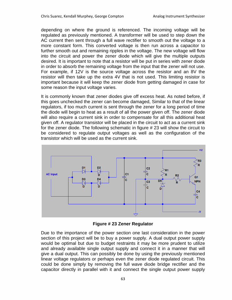
Chris Suarez, Kendall Murphey, George Compton Analog Instrument Synthesizer
63
depending on where the ground is referenced. The incoming voltage will be regulated as previously mentioned. A transformer will be used to step down the AC current then sent through a full wave rectifier to smooth out the voltage to a more constant form. This converted voltage is then run across a capacitor to further smooth out and remaining ripples in the voltage. The new voltage will flow into the circuit and power the zener diode which will give the multiple outputs desired. It is important to note that a resistor will be put in series with zener diode in order to absorb the remaining voltage from the input that the zener will not use. For example, if 12V is the source voltage across the resistor and an 8V the resistor will then take up the extra 4V that is not used. This limiting resistor is important because it will keep the zener diode from getting damaged in case for some reason the input voltage varies.
It is commonly known that zener diodes give off excess heat. As noted before, if this goes unchecked the zener can become damaged, Similar to that of the linear regulators, if too much current is sent through the zener for a long period of time the diode will begin to heat as a result of all the power given off. The zener diode will also require a current sink in order to compensate for all this additional heat given off. A regulator transistor will be placed in the circuit to act as a current sink for the zener diode. The following schematic in figure # 23 will show the circuit to be considered to regulate output voltages as well as the configuration of the transistor which will be used as the current sink.
Figure # 23 Zener Regulator
Due to the importance of the power section one last consideration in the power section of this project will be to buy a power supply. A dual output power supply would be optimal but due to budget restraints it may be more prudent to utilize and already available single output supply and connect it in a manner that will give a dual output. This can possibly be done by using the previously mentioned linear voltage regulators or perhaps even the zener diode regulated circuit. This could be done simply by removing the full wave diode bridge rectifier and the capacitor directly in parallel with it and connect the single output power supply

Chris Suarez, Kendall Murphey, George Compton Analog Instrument Synthesizer
64
directly to either circuit. This would remove any or most of the potential human error in regulating the AC current. The SOLA power supply at hand when wired for the proper 220V input will give an output of 24V @ 2.4A this has found to be sufficient and may act as a proper back up in case other attempts at the power regulation fail.
3.21 Pedi-Ergonomic Design There are a few common methods of implementing expression pedals in modern day guitar effects pedals. There are two distinct ones and an original design that are being considered for this devices expression pedal.
The first design requires a toggle button or foot pedal in addition to the analog expression pedal. The button will toggle the oscillator that drives all of the oscillator related effects, turning it on and off. The expression pedal will then control the frequency of the oscillations depending on how far it is depressed. The advantage of this pedal design is that it allows the user to save the selected frequency and toggle it on and off with the button. The disadvantage of the design is the fact that it requires two pedals, and that only one of them can be used at once.
The second design just uses the expression pedal by itself. The expression pedal is spring loaded so that it strives to be in the upright-most position. While there is no pressure on the pedal, the oscillator is turned off and the effect is simply bypassed. Once pressure is placed onto the pedal, the oscillator kicks on, and the frequency is decided by the distance the expression pedal is depressed by as normal. To turn the oscillator back off, the user then stops applying pressure on the pedal to allow it to return to its upright off state. The advantage on this design is that there is only one pedal, meaning fewer things for the user to have to think about while playing. The disadvantage is that the user has to start and stop oscillating at the same frequency every time. The user will be unable to start or stop immediately at a higher frequency and will have to wade through all of the lower frequencies to stop oscillating. There are several models of expression pedals that include functionality for both this option and the first, all within the two pedals of first option. The Ibanez Weeping Demon is a terrific example of this. Its default mode allows the user to implement the first suggested design, and then with the flip of a lever it engages the spring and the second suggested design is activated. For the scope of this device, a “double action” implementation of the expression pedal will likely be difficult to construct and not terribly useful. The second design, simply put, is just not an appropriate way to handle the frequency modulation for this devices needs.

Chris Suarez, Kendall Murphey, George Compton Analog Instrument Synthesizer
65
Figure # 24 - Side-view of third pedal design.
The third, original design is to combine the two ideas. There will be a spring loaded expression pedal and another digital pedal. The digital pedal will be placed so that it lies under the heel of the foot as it is using the expression pedal. The heel of the foot will be able to depress the pedal to switch the oscillator on and off, while the toes of the foot will be able to select a frequency for the oscillator. This will allow the user to gain the advantages of both previous designs with none of their drawbacks. There is one minor drawback to the design, being that it may require a fair amount of practice to get the desired effects. The user is already coordinated enough to play guitar, so it can be seen as a non-issue.
Chapter 4: Construction 4.1 Parts List Integrated Circuits
• AD633 o Low cost analog multiplier. Features four-quadrant multiplication
with no external components required. Chosen as a cheap means of implementing the various multiplier circuits within the device.
• MPY634 o Wide bandwidth precision analog multiplier. Features four-
quadrant multiplication with a wide bandwidth of 10MHz. Another option for multiplying circuits within the device. Proved to be unusable for the devices specific needs, in addition to being rather expensive.
• LM393 o Dual differential comparators. Designed to operate from a single
power supply over a wide range of voltages. Used within the device for managing digital selector circuitry and square wave transformation.

Chris Suarez, Kendall Murphey, George Compton Analog Instrument Synthesizer
66
• 1N4148 o High speed diode. Features a maximum switching speed of 4 ns
with a maximum reverse voltage of 100V. Used extensively through the device as a sort of general purpose diode.
• NA555/NE555 o Precision timer. Features timing from microseconds to hours and
adjustable duty cycles. Used for implementing the chopper guitar effect in addition to providing a clock pulse for various other oscillators.
• TL084 o JFET-input operational amplifier. Features low power consumption
and output short circuit protection. General purpose opamp used throughout the entire device.
• LF351 o JFET-input operational amplifier. Similar in behavior to the TL084,
but comes in a single package instead of the 4 package. Used when a circuit calls for fewer than 4 opamps.
• OPA277 o High precision operation amplifier. Features a very low offset
voltage of 1µV and a very high open loop gain. Necessary for circuits that require higher precision within the device.
• 1N914 o Fast switching diode. Used as a possible alternative to the 1N4148
within the circuit as a general use diode. Will require lab testing to prove which is more suitable for the device’s needs.
• UC2843 o Current mode pulse width modulator controller. Optimized for off-
line and DC to DC conversions and a low startup current. For use within the oscillator circuit to adjust pitch of guitar signal.
• LM324 o Quadruple operation amplifier. Features four high gain frequency
compensated operational amplifiers designed to operate from a single supply. Possible alternative to the TL084, will require lab testing.
• LM2907 o Frequency to voltage converter. For use within the circuit as a
tachometer for scaling gain, used in the triangle wave transformation circuit.
• LM7907/LM7809 o Negative fixed voltage regulator. Features current limiting and
thermal shutdown as fail safes. For use within the power circuitry to help provide consistent power to all of the ICs in the device.
• TPS54810PWP

Chris Suarez, Kendall Murphey, George Compton Analog Instrument Synthesizer
67
o Output synchronous Buck pulse width modulator switcher with integrated FETs. Used for AC to DC conversion to step down the higher voltages. Only to be used if the alternative is too inefficient, will require testing.
• 1N5711 o Small signal Schottky diode. Features a high breakdown and low
turn-on voltage, with ultrafast switching. Used for low voltage drops within the power circuitry, and for diode O-Ring.
• LT1512 o Constant-current/constant-voltage battery charger. Regulates
power for charging batteries up to 30V. Will be used within the device to charge rechargeable batteries for “wireless” use.
• Heat sink o Possibly necessary for cooling the power circuitry. Will require
testing to determine if heat load is too high without them. • Arduino Uno
o Prebuilt programmable microcontroller. Used for managing the digital selector circuitry for the user interface.
• PT2399 o The PT2399 is an echo audio processing integrated circuit. This
circuit utilizes CMOS technology. This chip was chosen because of its low price and the ease of use. This chip samples signals and gives appropriate outputs.
• LM331 o Precision voltage-to-frequency converter. Wide range of
frequencies that encompass audible frequencies. May be used to drive oscillatory circuits.
Tools
• Function Generator : AFG3022B o Used in a lab environment to help simulate guitar inputs in a
controlled setting. Also useful for simulating signals mid-stage for fine-tuning the circuitry.
• Bread board o Standard prototype breadboard. Used as a platform for testing
prototypes designs. • Oscilloscope: DPO 4034B Mixed Signal
o Used in conjunction with the function generator to observe steady responses to steady sinusoidal inputs. When testing for the particular sounds of a circuit, the oscilloscope will not be used.

Chris Suarez, Kendall Murphey, George Compton Analog Instrument Synthesizer
68
4.2 Printed Circuit Board Design The entirety of our project to be constructed is compromised of through hole components. Each of these oscillatory designs and the power system will have to be correctly soldered together. We can choose to preorder a printed circuit board based on design specifications or a printed circuit board could be made at home.
If chosen to make our own circuit board it is made possible using common house hold items. Using PCB software such as eagle will allow the ability to compose a layout of a schematic of the s circuit design. After the design for the pedal is established it will be printed, using a laser printer, onto a cheap glossy paper such as the type used for magazines and junk mail. Be careful to help feed the paper into the printer since this is not the intended paper type for it.
After the layout is printed onto the paper one must prepare the raw PCB material. For cutting the board the best way is to use either a blade or a glass cutter in order to etch out a groove into the material. Once this etch is deep enough the next part is a simple as breaking the board by hand.
Now that the board is roughly broken to size it is important to clean the board and remove any grease that may have collected on its surface. Using an abrasive sponge and soap should do the trick for this step. Make sure to rinse this copper surface until clean and shiny. After it has been thoroughly cleaned one just will have to rinse and dry the copper surface with a clean cloth or paper towel.
Next is to transfer this printed design onto the copper plate. We cut the magazine paper to size with enough room to fix the paper to a flat surface. This surface must be a heat resistant material. Once mounted to a proper surface the printed paper is then ironed onto the copper plate. This is accomplished by setting a household iron to its highest setting and pressing the iron down onto the material long enough for the printed circuit design to transfer over onto the copper plate. After the transfer has been completed let the board cool down.
After the board is cool enough to touch soak the board for about a minute in water until the remaining paper is wet enough to rub it off of the board. The toner should not scratch as it should bond to the copper fairly well.
The best way to etch away at the copper board is to soak it in an etching material such as ferric chloride and let it set for roughly 15 minutes. Stir the board around in the liquid to ensure a nice even coating across the board.
After the board is properly etched rinse it with a lot of water. Once rinsed and dried apply a small amount of thinner, or nail polish remover, onto a cotton ball and remover any remainder of the printer toner. This step should bring back the copper surface. Rinse again, very carefully, with water and dry with a clean cloth or paper towel. Sand and resize the board to desired specifications and then end result is a homemade printed circuit board.

Chris Suarez, Kendall Murphey, George Compton Analog Instrument Synthesizer
69
The homemade approach maybe more feasible since the pedal project will require a large amount of PCB. As stated previously most of the required materials should be located around the house with exception to the ferric acid and board material.
If it is determined that this is not the route to go the circuit layout will carefully be put together and sent to a company to have the board fabricated professionally.
4.3 Housing The construction of the housing for the device is going to require a fair amount of handiwork, at least with the casing that contains all of the pedals and knobs. The main bulk of the device can be housed within a computer tower, so the only construction needed there is mounts for the various printed circuit boards. For aesthetic reasons, there is likely going to be plates of the case removed in order to be replaced by plexiglass. The plexiglass will allow anyone to look inside the unit without having to take anything apart. There will also likely be colored LEDs, again for aesthetic reasons, placed within the device to turn on and off with the signal. This could potentially prove to be useful if LEDs could be placed to match the output of any low frequency oscillators currently in use.
For the pedalboard itself, it will require constructing an ergonomic layout that has user interface properties. A series of buttons, knobs, and pedals will need to be installed into the pedalboard, in addition to a possible display for the user. The switches themselves should not be terribly hard to obtain as they are commonly used in many if not all modern pedals. The chassis for the pedalboard will need to be constructed out of a light yet strong material, likely aluminum. It will either need to be constructed in a box shape using flat sheets or will need to be shaped and rounded. Both ideas are still up in the air as it stands.
Chapter 5: Testing & Usage 5.1 Survivability The survivability of this project will not be that extensive. This device is designed to rest flat on the ground leaving it vulnerable in some instances. The device itself will be stepped or stomped on as is the very nature of a guitar pedal. It will have to handle the effects of forces being pressed down on the housing, the

Chris Suarez, Kendall Murphey, George Compton Analog Instrument Synthesizer
70
pedals, and the buttons themselves. It will be attempted to have the knobs recessed enough into the casing that they will be protected from being stepped on. Certain precautions will have to be taken with the housing to ensure that the device cannot be easily damaged during transfer of the device. Also, since the device could stand alone and operate it has to be taken into consideration that the device should not be easily kicked or knocked over and possibly damage the device. Reinforcements should also be made to the power system that will handle the AC to DC conversion. If the cord to the pedal is stepped on, pulled, or kicked the integrity of the inner components must be maintained.
Due to the possible heating problems of the power system it will be required to maintain a safe temperature for all circuitry within the housing. This may require some heat sinking techniques as discussed previously. Any holes cut into the housing to allow the circuitry to “breathe” must be placed in a way so that dust and foreign objects cannot make their way into the pedal and possibly shorting the device.
Vibrations from the actual music being played also will be considered. When building the housing and installing the printed circuit board. While most vibration levels may not be so extreme, it may still be important to look at some of the different techniques used to protect against damage from vibrations. There are a couple of ways to reduce vibrations.
One such method is using foam to encase sensitive circuitry and isolate it from possible vibrations. Problems with foam are the foam, if improperly chosen, can allow the device to overheat by cutting off air flow or insulating heat given off by the very circuits that are being protected. Some new foams that have been developed to protect a circuit would be black neoprene foam, silicon foam, and vinyl foam.
Other damage may not be to the electrical components of the device. Sometimes damage can be caused to the actual hardware of a device. The most common damage from vibration is to screws and other fasteners. In order to prevent such damage one can ensure that these are made of thermoplastic material.
5.2 Robustness The robustness of the guitar pedal will not be so extensive. In general most pedals are pretty straight forward. The one in this design will have one actual input from the guitar and the output will be lead into an amplifier. The device itself will have two pedals.
One is to control the oscillation of the output and the second will allow the user to select what type of waveform will be implemented. Next to the pedals will be the switches to add the actual effect to the waveform. Each one will be pushed and

Chris Suarez, Kendall Murphey, George Compton Analog Instrument Synthesizer
71
used one at a time. LEDs will be fixed to each switch to indicate which has been selected.
5.3 Stress Testing Physical stress will be a big factor for this project. Due to its very nature the pedal box itself will have to withstand being stepped and stomped on while the user is changing certain attributes of the pedal. This will require a sturdy casing, knobs, and switches. Since the outer casing will more than likely be homemade and not professionally done some special care will need to be taken when testing the outer housing for any weaknesses to stress. Please note that before even beginning this process that the test on the box will be done while it is empty. For obvious reasons, this is if in case the box was to fail nothing else will be damaged. Preliminary testing of the box or the pedal will not be as extensive as it will be required to withstand around 250 pounds. This will be achieved by placing someone, or a set of weights, of a predetermined weight and having the stand on various sections of the pedal. This will test for possible weak points in the enclosure. For every time that the guitar pedal passes weights will be added to increase the amount of pressure added to the enclosure. This will be repeated until we reach the desired amount of weight to be tested. Materials to be considered for makeup of this enclosure would be a plexiglass enclosure reinforced with a steel frame. This would be a relatively cheap material for it durability and easier to work with while building it at home.
5.3.1 Stress Testing (Electrical) Given the length of time the pedal will be plugged in it will be important to test the voltage regulators to ensure that the heat sink fitted on them will meet requirements. This is done by calculating the amount of power which is dissipated from inside the regulator. This is done by following equation # 5.
Pdissipated=(VIn-Vout)*Iin
Equation # 5
To ensure the device will not overheat it may be required that holes are drilled into the enclosure to ensure that the device will have a decently controlled ambient temperature. Another design is the actual heat sink of the voltage regulator. It is important to check the temperature constraints on the datasheet for each regulator against the heat expected to be dissipated.
In the event that the heat dissipated by the regulator or the device in general it will be important to implement a type of heat sink. What type is used is dependent on the constraints given by the pedal design. There are two different types of heat sinks.

Chris Suarez, Kendall Murphey, George Compton Analog Instrument Synthesizer
72
Active heat sinks are powered by the device and only add to the overall load that the power system has to handle. This may not be a suitable solution to the pedal. If an active sink is chosen this normally would consist of a can used to pull cooler air into the device to lower the ambient temperature and/or utilize a second fan to act as an exhaust to remove hot air from the internal workings of the device. This not only provides more of a power drain on the power system design, but it will also add to space issues to an already large pedal design.
Passive heat sinks are the more reliable option that will require no power. These sinks are normally made up of aluminum and designed with fins that will conductively dissipate heat. Even though these are more reliable it is recommended that a steady air flow move across the fins in order to help with dissipation. Although this method will not add to the power system constraints, a passive filter will still require some room on the PCB and this will have to be taken into account.
Another consideration for testing the equipment is to take precautions from condensation. Due to holes located in the coating there is also danger of the device getting wet from the environment around it. Dust and dirt may also be able to collect inside the device due to these holes requiring another preventative measure. One measure against corrosion on the leads would be conformal coating.
Conformal coating is a technique used to protect a printed circuit board from harsh environments. This will prevent damage and/or failure of the electric components. Another plus to this technique is that if the proper type of material is chosen for the coating it may actually prove to reduce the effects of mechanical stress, have a certain resistance to higher temperatures, and any vibrations introduced to the circuit.
Application of the conformal can be applied a number of ways. This can be applied by brushing, spraying, dipping, or even using a robotic arm to coat the printed circuit board. Selection of the method depends on the substrate that is to be coated, the performance of the actual coating, and the throughput requirements of the actual board. Once coated there are also different methods of curing and drying depending on the material used.
Brushing the conformal coating is an application used for low volume purposes, finishing of the coating, and general repair. This is an inferior method cosmetically and can open the potential to future defects such as bubbles. If applied improperly the overall quality of the coating may not be consistent and can be thicker in general.
Spray application can be applied with a spray aerosol or a spray booth fitted with a spray gun. This application is a good option for low and medium volume processing. This method has the best surface finish and, if done appropriately, will have no defect issues.
Chris Suarez, Kendall Murphey, George Compton Analog Instrument Synthesizer
73
Dipping is a very effective and repeatable process that can prove to be the highest volume technique. This coating method will penetrate everywhere including underneath the device. This requires that if there is any 3D effects that must be masked it must be done perfectly in order to prevent leakage. Due to the construction of the PCB some boards maybe prove unsuitable for the dipping process. Some of the coating material can become uneven around edges. This can be remedied by double dipping the printed circuit board or even spraying layers of material to give better coverage.
Lastly the robotic application is addressed. This is done by needle and atomized spray, non-atomised spray or ultrasonic valve technologies. These hang just about the circuit board and will dispense and/or spray the coating material in selective areas. Different flow rates and viscosity of various conformal materials are programmed into a computer system. The computer takes this data and uses it to control the applicator so the desired level of thickness of the material is maintained. Even though this method can be a very precise way to coat the board it will only be high volume method if the circuit boards are actually designed for this application process. Limitations to robotic application are that low profile connectors can get coating taken away from the printed circuit board.
Depending on the type of conformal coating there is a specific drying method that is applied. For the standard solvent based acrylics simple air drying will suffice except when under time constraints. If under such a time crunch it is also typical to use batch or inline ovens with cure profiles to get efficient curing. Water based coatings are treated the same way. The only thing to be concerned with these solvents is the application of heat due to slower drying times.
A growing curing method is the UV curing of conformal coating. This method has become popular for higher volume users. This has become such a popular coating type due to its rapid cure speed, ease of the processing level, environmentally friendly, and thermal cycling resistance.
Interference from radio signals can also get into a signal and create unwanted noise in the output of the pedal. This sometimes can be the wiring to the outlet that the pedal is powered to. If not properly the wiring in the house is not grounded completely this interference signals can travel from the ground through the wiring of a house or building and to the pedal. If the wire connecting to the ground is not mounted properly or loosened this is cause for a poor ground. The other factor could be that the metal is not connecting to the ground properly. Either way, if the interference is from an improper ground there is a fix for this.
Even though some pedals may already have this feature a vast majority still come without. The key to this issue is to filter out the noise before it is able to enter the pedal. Running the input signal through a passive low pass filter will allow only the music being played to pass through and remove radio interference. Initial testing will be made to the pedal to see if a passive box, otherwise known as the filter, is needed.

Chris Suarez, Kendall Murphey, George Compton Analog Instrument Synthesizer
74
A more physical aspect to testing the electrical portion of the pedal is to make sure that the inputs to the pedal will hold the jacks from the cable firmly in place. The inputs themselves will be reinforced on the housing to make sure that no physical damage will occur if the cables were pulled or tugged on. Secondly, the inputs should be fitted with a rubber gasket to ensure the jack will grasp and fit snuggly.
5.3.2 Stress Testing (Mechanical) The pedals are a key part and one of the few mechanical aspects that will have to be tested. The pedals should be able to handle a single force being pushed against them. Proper reinforcements will have to be made ensure the right sturdy material is used to ensure lasting durability. An attempt at building two pedals will be made. If testing proves that the construction of the pedals is not feasible then it will be considered to use a pre-fabricated from another pedal box.
The knobs on the guitar pedal itself will have to be tested as well. Since the housing is being built, certain reinforcements will have to be made where the knobs are fitted into the box. These will also receive single concentrated amounts applied to them. It is important that this applied pressure does not compromise the box or the knob design.
Chapter 6: Conclusion 6.1 Obstacles Overcame There have been many obstacles overcame in the design of this box and there are sure to be more in the next semester when the final design should be completed.
First one of the major obstacles has been an understanding of grounding. It wasn’t understood before this project that there is a complete difference between analog and digital ground. The analog ground was the one that was most comfortable and it was at the node between the dual nine volt batteries, while preforming small voltage test in the lab. This part of the circuit was familiar because of the analog labs that are offered at UCF. However once there was a digital aspect introduced in this mix circuit design this was completely uncharted

Chris Suarez, Kendall Murphey, George Compton Analog Instrument Synthesizer
75
territory. This subtle difference was actually the difference between some of the parts working and not making a desirable noise at all. This was something that wasn’t in any of the class that has been taken so far. Where was this noise coming from? Were separate power systems necessary to solve this problem? At first that was actually the decision that was decided as a group. However in the lab a break through happened from accidentally misconnecting the separate power sources. The analog parts and the digital parts were connected to the same source however the power system acted like a barrier between them. After more research it was found that this was actually a common way of preventing the digital noise from affecting the analog devices. After more research it was found that this is actually a common and very efficient method filtering out the digital noise.
One major obstacle that was encountered was with the reverb effect. The way that analog reverb is created is through the vibrations of the speakers in a guitar amplifier. The speakers vibrate the cab that houses all of the electronics, and in the electronics is a spring. The spring ends up picking up the vibrations of the speaker and oscillates for a relatively long period of time. Inductors sense the disturbance in the spring and generate a voltage that is also oscillatory and used to manipulate the original input signal. The resulting sound is a mild echo, and is largely sought after amongst most musicians. Unfortunately reverb cannot be replicated in this device because there is no speaker built into the device. Thus, there is nothing for the spring to pick up on. Modern devices simulate the reverb effect by using digital networks, artificially adding the echo sound to the circuit. Because the effects processing performed by this pedal are purely done in analog, adding an FPGA just for this one minor effect would be far too costly.
For the triangle wave, there were a handful of obstacles that were hit. The main one was the lack of a spice model for the LM2907 component, which is necessary for producing a voltage that is dependent on frequency. Because of the lack of the spice model, this part was unable to be simulated, and thus the triangle wave design was unable to be fully implemented. The part will need to be either purchased or received as a free sample and then tested within a lab environment to fully try to implement the frequency to voltage conversion used to scale the gain on the triangle wave circuit. It may not be necessary, but it is still worth looking into. In either case, some form of very reliable and consistent frequency to voltage conversion is going to be necessary for any of the ramp related waves, namely the triangle wave and the saw wave.
Another obstacle that was hit for the triangle wave was attempting to implement a form of frequency dependent resistance. The overall goal of the part was to use it as a gain controller, so that the subcircuit could be used as one of the resistors in a non-inverting amplifier. When the subcircuit produced a lower resistance, the gain would increase and vice versa. The primary design chosen was to use two NMOS components and a very small capacitor, all sharing the same node. The capacitor is tied to ground, while the source and drain terminals of the NMOS components are subjected to the unscaled triangle wave. The gate terminals of

Chris Suarez, Kendall Murphey, George Compton Analog Instrument Synthesizer
76
the NMOS components are connected to two square waves that are 180 degrees out of phase to each other. The obstacle that was hit was that this circuit was not working at all like planned, behaving almost erratically. The obstacle was overcome when it was determined that the square waves can never overlap each other. Because when the squares overlap, the 2 NMOS components are opened up and a short is created, ruining the waveform. Now that the subcircuit is behaving correctly, it can be added to the list of potential designs for the triangle wave circuitry, and indirectly the sawtooth wave circuitry.
When dealing with the design of the power system one has to deal with is attempting to modify a rechargeable circuit that has the capability to recharge a battery while preventing it from overcharging. The rapid charge circuit involving the LT1510 will all be done while being attached to the AC to DC conversion in a way that will use its transformer to power the recharging of the battery.
While there are common practices that do this very thing this project will require certain modifications. This recharging circuit must not only prevent from overcharge but be able to allow the battery to stay in place and power a dual rail circuit that will in turn power the pedal.
6.2 Ideal vs. Non-Ideal Testing The next one of the major obstacles that were needed be overcame was problems using LTSpice as a simulator. Overall this product is a great product. But there were some difficulties that were needed to be overcome.
LTSpice was made by linear technologies, so it only has either ideal parts or parts made by linear technologies. Since this device has parts that are made by more than just linear technologies then this is would definitely cause problems when trying to use this simulator. The design of this simulator was so that 3rd party models can be coded into a spice model. And any part that has been coded into a model spice can be implemented in this circuit. There this was a very useful feature to this program. This useful feature was actually very, very difficult to implement. There were many types of spice models and some were intuitive and could be implemented simply by downloading a spice model to a library and taking the ideal form of the circuit and renaming the parameter.
However, some were not this simple to implement and they needed a lot of altering in the computer. This was especially difficult when using the computer labs on campus because they wouldn’t allow the users to download certain types of files and certain folders couldn’t be altered which made simulations of third party devices difficult while on campus. The best idea was to use the linear technologies substitutes for these types of devices. This method ended up working well for most the parts with minor variations from the simulation of the actual spice model which was usually negligible.

Chris Suarez, Kendall Murphey, George Compton Analog Instrument Synthesizer
77
Linear Technology makes a wide variety of integrated circuits, so for almost any of their competitor’s circuits they usually have a part is similar. However this would cause problems when using a device such as the AD633 or MPY634. These are analog multiplying devices. Linear technologies didn’t make an analog multiplier so it was unable to be implemented using the simulator on campus. Also, there was no working spice model of the MPY634 available. At the time simulations were being performed on the multiplying circuits it was thought that the AD633 was a viable substitute. In most applications this would definitely be the case, both the MPY 634 and the AD633 were designed to be used in a wide frequency range. However the MPY634’s definition of a wide frequency range was very different than the AD633’s definition of a wide range. The MPY634 was designed to work at a range of 10 kHz and above which is way out of the audible range of any instruments. The AD633’s spice model however indicated that this device would work perfectly in the applications that were simulated. Now, not only was there possible difference between parts that needed to be accounted for, there were also the differences between real and the simulated spice model parts.
When taken to the lab it was discovered that the MPY634 didn’t begin to start acting in a predictable fashion until at about the 1 kilo hertz range. At lower frequencies it lost gain and also became very muddled. This was a definite problem when dealing with a schematic that only works on a quarter of the notes on the guitar neck. There were a couple methods implemented to try and offset this problem however none of them really preformed that well. The first attempt was a voltage controlled amplifier this actually worked just like in the simulator but when hooked up the output was very muddled on the low ends and completely unacceptable. A switching capacitor circuit was also attempted this circuit wasn’t able to be implanted in the spice correctly but it worked in the final design as an amplification. The reason this was even attempted where the other amplifier failed was the use of the capacitor and other bypass capacitors was thought that maybe this could clean up the noise that was modulated on the low end of the fret board. But this was to no avail. The MPY634 was clearly not the device for this job.
The AD633 on the other hand worked amazingly and when implemented in the lab gave very clear outputs that matched the modeling of the 3rd party spice model. This was a case of not only modulation problems but the right tools to complete the task correctly.
Some difficulties in the lab also arose from the inability to find coherent spice models for some of the parts used for them or any of their counterparts. Below are a few examples and some of the headaches that were caused and some of the fixes that were used.
The first one of the most basic of parts that is in every single one of our blocks in the block diagrams that isn’t capable of implementation in LTSpice is the potentiometer. This is one of the most fundamental devices when it comes to integrated circuits. It is in almost every design and yet there wasn’t a function for

Chris Suarez, Kendall Murphey, George Compton Analog Instrument Synthesizer
78
this to be implemented in the simulator LTSpice. Actually, after some research it was found that one of the engineers that designed the software felt so adamantly about the ability to use a potentiometer he wanted to make sure the other designers didn’t put this device in LTSpice. He wanted everybody to use only two resistors in voltage divider formations. This seemed very odd however he was the software engineer that designed LTSpice so apparently every user of his technology was at his mercy.
While looking for spice models for 3rd party operational amplifiers it was discovered that there was a model of a potentiometer that someone had made online but this device had to be synthesized in the design a part portion of LTSpice then the spice file had to be downloaded. This wasn’t bad if it only had to be done once but every time a new computer opened up a file with this part in the schematic this process had to be repeated. It ended up being way too redundant and the executive decision was made not to use it in any of the schematics that were to be implemented. There were a few problems with this however it made it less clear which portions of the designs were actual voltage dividers and which devices were just a simulation of a potentiometer. Also, while simulating it was more convenient to just slide the potentiometer instead of adjusting the values of two separate resistor values.
The next headache came when implementing certain types of relaxation circuits. There were many diagrams shown online of these relaxation circuits that might make useful low frequency oscillators using different operational amplifiers, resistor, and capacitor logics. When these were simulated none of them worked. It was thought that maybe these were functions that worked more in theory but needed heat compensation or some sort of input, and that it was probably best to stay with integrated circuits. The 555 timer was able to fill most of these needs but the circuits had to be adjusted and were much more cumbersome than what was preferred. It was discovered shortly after that these oscillating devices weren’t working simply because an initial conditions box wasn’t checked in the pop up box of the edit command simulator. This was definitely very aggravating after this was discovered these oscillators worked much like the simulations, but circuits were already constructed using the 555 timer so it was decided to just leave it for now.
Overall LTSpice has proven to be very good software but some of these headaches would have been very nice to avoid. For most applications everything was very accurate and the results from the lab matched the results in the spice. There were minor differences in some of the resistor values and capacitor values but this was probably dude to errors in the components themselves.
6.3 Final Discussion This has been a very labor intensive project so far. This has just been mostly the design portion of this project but it won’t be easier from here. Some of the distortions and modulations have proven to be a little more difficult than

Chris Suarez, Kendall Murphey, George Compton Analog Instrument Synthesizer
79
previously expected. The oscillators proved to be especially difficult to control. Also the wobbling effect that preforms pitch modulation is very difficult to perform. There are many circuits and integrated circuits that preform this on a higher frequency range, but on our frequency range it’s proven to be difficult.
However some of the waveform shape modulations that were thought to be very difficult ended up not taking as much time as though. The goal is to have every part simulated and implemented on the proto boarded by the end of January.
This will allow us enough time to design a final PCB board and order it. While waiting on the PCB to ship this time could be utilized designing housing structures. The size of the PCB will have a large impact on how the final housing will be implemented.
The PCB will be expected to be finished by the end of February. At this time the housing and layout will be the focus of the project. This is expected to be finished by March. This should leave enough time to finish the final write up in time to focus on finals.

Chris Suarez, Kendall Murphey, George Compton Analog Instrument Synthesizer
80
Appendices
A.1 Block Diagrams

Chris Suarez, Kendall Murphey, George Compton Analog Instrument Synthesizer
81
Final Working Schematics
A.2 Distortion Schematic

Chris Suarez, Kendall Murphey, George Compton Analog Instrument Synthesizer
82
Koviak Schematic

Chris Suarez, Kendall Murphey, George Compton Analog Instrument Synthesizer
83
Square Wave Generator

Chris Suarez, Kendall Murphey, George Compton Analog Instrument Synthesizer
84
Octave booster Schematic

Chris Suarez, Kendall Murphey, George Compton Analog Instrument Synthesizer
85
Chopper Schematic

Chris Suarez, Kendall Murphey, George Compton Analog Instrument Synthesizer
86
A. 3 Bibliography Analog Devices, “Low Cost Analog Multiplier,” AD633 datasheet, 1999
Burr-Brown Products from Texas Instruments, “High Precision Operational Amplifier,” OPA277 datasheet, March 1990 [revised April 2005]
Burr-Brown Products from Texas Instruments, “Wide Bandwidth Precision Analog Multiplier,” MPY634 datasheet, December1995 [revised December 2004]
Design of analog filters Rolf Schaumann - Valkenburg M. E.Van - Valkenburg M. E.Van - Oxford University Press - 2010
Microelectronics: circuit analysis and design Donald A.Neamen - McGraw-Hill - 2010
National Semiconductor, “Wide Bandwidth JFET Input Operational Amplifier,” LF351 datasheet, April 1998
NXP Semiconductors, “High-Speed Diodes,” 1N4148 datasheet, Aug 2004
Texas Instruments, “Current Mode PWM Controller,” UC2843 datasheet, Apr 1997 [revised June 2007]
Texas Instruments, “JFET-Input Operational Amplifiers,” TL084 datasheet, Feb 1977 [revised Sept 2004]
Texas Instruments, “Low Power Low Offset Voltage Dual Comparators,” LM393 datasheet, May 2004
Texas Instruments, “Precision Timers,” NA555/NE555 datasheet, Sept 1973 [revised June 2010]
Texas Instruments, “Quadruple Operational Amplifiers,” LM324 datasheet, Sept 1975 [revised March 2010]
The art of electronics Paul Horowitz - Winfield Hill - Cambridge University Press - 1989
Vishay, “Fast Switching Diode,” 1N914 datasheet, Feb 04

Chris Suarez, Kendall Murphey, George Compton Analog Instrument Synthesizer
87
A.4 Index
Tables Budget Summary 13
Housing 13
Regulators 57
Equations
Frequency (VCO) 44
Time Interval (Pos/Neg) 44
Maximum Input voltage (Recharge) 59
Power Dissipation 71
Figures
Chopper 35
Diode Oring 61
Distortion 18
Flanger 51
Koviak 32
NMOS subcircuit 27
Pedal design 54
Pedal (side view) 65
Recharge circuit 59
Rectifier wave 24
Reverb 52
Saw-tooth wave 29
Saw-tooth block diagram 1 30
Saw-tooth block diagram 2 31

Chris Suarez, Kendall Murphey, George Compton Analog Instrument Synthesizer
88
Shark fin wave 35
Square wave 22
Tremolo 46
Triangle block diagram 1 26
Triangle block diagram 2 26
Triangle wave 24
VCO (555 timer) 43
VCO (Multi-Output) 45
Wein bridge circuit 42
Zener diode regulator 63


![Ece-III-Analog Electronic Ckts [10es32]-Notes](https://img.pdfslide.net/doc/110x75/55cf9da2550346d033ae7b1a/ece-iii-analog-electronic-ckts-10es32-notes.jpg)