Embed Size (px)
Citation preview
Analog Interfacing
Introduction In this module, we will consider the steps required to select and apply TI Analog components to your TI DSP system.
Objectives At the conclusion of this module you should be able to: • List various families of TI Analog that relate to DSP systems • Demonstrate how to find information on TI Analog components • List key and additional selection criteria for an ADC converter • Identify challenges in adding peripherals to a DSP design • Identify TI support to meet above design challenges • Describe the types of Analog EVMs available from TI • Create driver code with the Data Converter Plug-In • Apply Plug-in generated code to a given system
TMS320C6000 Integration Workshop - Analog Interfacing 6.5 - 1
Module Topics
Module Topics Analog Interfacing..................................................................................................................................... 6-1
Module Topics......................................................................................................................................... 6-2 TI Analog Portfolio ................................................................................................................................. 6-3 Getting Information ................................................................................................................................ 6-4 TI Data Converters ................................................................................................................................. 6-7 Selecting an Example ADC..................................................................................................................... 6-9 Development Challenges........................................................................................................................6-10 Analog EVMs .........................................................................................................................................6-11 Data Converter Plug-In .........................................................................................................................6-12 Lab 6.5: Analog Interfacing...................................................................................................................6-17
A. Selecting the optimal device .........................................................................................................6-17 B. Assembling the Hardware............................................................................................................6-18 C. Using the Data Converter Plug-in ................................................................................................6-19 D. Integrating the New Code to the Existing Project........................................................................6-20 E. Load & run the new code, observe performance..........................................................................6-21
Conclusions............................................................................................................................................6-23 Additional Information...........................................................................................................................6-24
6.5 - 2 TMS320C6000 Integration Workshop - Analog Interfacing

TI Analog Portfolio
TI Analog Portfolio
Interfacing TI DSP to TI Analog
TI Analog
ADC
Data Trans
POWERSOLUTION
DAC
OP-AMPs/Comparators/Support- High Speed Amplifiers- Low Power, RRIO Signal Amps- Instrumentation Amps- Audio Power Amps- Power Amps- Commodity Amps- Comparators- Temp Sensors- References- Special Functions
Data Converter-Standard A/D and D/A- High Resolution/Precision converters- High Speed converters- Touchscreen controllers- μ-Law/A-Law Telecom “SLAC”s- Communication, Video, & Ultrasoundoptimized converters/codecs
- Audio & Voice band converters/Codecs- Industrial converters
Data Transmission- Many standards- SERDES
STANDARDSRS232RS422RS485LVDS1394/FirewireUSBPCICANSONETGigabit EthernetGTL, BTL, etc.
Power- Power Modules- Linear Regulators/ LDOs- DC-DC controllers- PFC- Load Share- Battery Management- Charge Pumps & Boost Converters- Supervisory Circuits- Power Distribution/Hotswap- References
(Codec)
RFRF (or Wireless)
DATATRANSMISSION
DigitalMSP430TI DSP
etc
ClockingSolution
Anothersystem/
subsystem/etc.
Data Trans
Clocks• Clock Buffer & fanouts• PLL based buffers & fanouts• Multipliers & Dividers• Jitter cleaners & synchronizers• Memory specific solutions• Synthesizers• Real Time Clocks
4
TI has long been a leader in the development and production of analog ICs. With the recent acquisitions of Burr Brown, Power Trends, and Unitrode, TI’s position as the world leader in the sale of analog ICs, placing in the first three positions in all major market segments demonstrates that TI is a good place to start when looking for analog ICs to round out a DSP based system.
Interfacing TI DSP to TI Analog
TI’s High-Performance Analog Portfolio
Technical TrainingOrganization
T TO5
TMS320C6000 Integration Workshop - Analog Interfacing 6.5 - 3
Getting Information
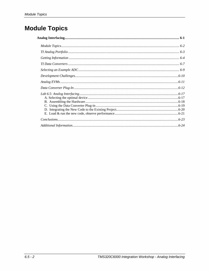
Getting Information
Interfacing TI DSP to TI Analog
http://analog.ti.com
Booklet : SSDV004NDSP Selection Guide
Booklet : SSDV004NDSP Selection Guide
8
From the home screen of the TI Analog web page, click on the element of interest and begin exploring the devices offered to best meet your needs. Also on this site is a wealth of support, from data sheets and app notes, to software development tools to help get the job done.
Interfacing TI DSP to TI Analog
On-Line Data Converter App Notes
Most contain downloadable software examples for use with CCS or Embedded Workbench!
Most contain downloadable software examples for use with CCS or Embedded Workbench!
Click on “Application Notes” from the Product Folder for links to specific devicesClick on “Application Notes” from the
Product Folder for links to specific devices
9
6.5 - 4 TMS320C6000 Integration Workshop - Analog Interfacing
Getting Information
Interfacing TI DSP to TI Analog
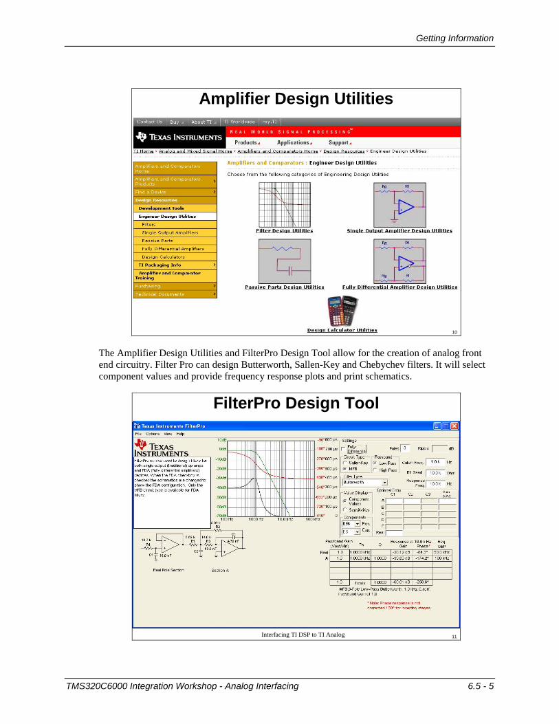
Amplifier Design Utilities
10
The Amplifier Design Utilities and FilterPro Design Tool allow for the creation of analog front end circuitry. Filter Pro can design Butterworth, Sallen-Key and Chebychev filters. It will select component values and provide frequency response plots and print schematics.
Interfacing TI DSP to TI Analog
FilterPro Design Tool
11
TMS320C6000 Integration Workshop - Analog Interfacing 6.5 - 5

Getting Information
Interfacing TI DSP to TI Analog
SWIFT Design Tool
12
SWIFT supports selection/design of TI power devices, providing values for capacitors, resistors and inductors based on the input parameters and analysis plots of current and voltage ripple of the design. The I-to-V tool is for use with current output DACS, helping in op amp selection and showing what effect the op amp they choose for doing I-to-V conversion has on DAC response.
Interfacing TI DSP to TI Analog
The I-to-V Pro Tool
13
6.5 - 6 TMS320C6000 Integration Workshop - Analog Interfacing
TI Data Converters
TI Data Converters
Interfacing TI DSP to TI Analog
Application Areas for TI Data Converters
EmbeddedHigh Perf. DSPPortable / Low PowerMicro Systems
High PrecisionMeasurementOver Sampling ?S ADCs
Precision ADCsMicro SystemsHigh Speed ADCsCurrent Input ADC’s
Touch-Screen ControllerStand-AloneIntelligentIntegrated Audio
AudioVoiceband CodecsConsumerProfessional Audio
High Speed Comm /UltrasoundPipeline ADCsCurrent Steering DACs
Industrial Control /InstrumentationSAR ADCs
High SpeedLow PowerSimultaneous SamplingBipolarData Acquisition Systems
String / R2R DACsSingle SupplyMonitor & ControlDual Supply
Technical TrainingOrganization
T TO15
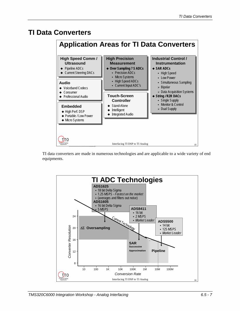
TI data converters are made in numerous technologies and are applicable to a wide variety of end equipments.
Interfacing TI DSP to TI Analog
1K10010 10K 100K 1M 10M 100M
24
20
16
12
8
Pipeline
SAR Successive Approximation
ΔΣ Oversampling
ADS162518 bit Delta Sigma1.25 MSPS - Fastest on the market(averages and filters out noise)
ADS160516 bit Delta Sigma5 MSPS ADS8411
16 bit 2 MSPSMarket Leader ADS5500
14 bit125 MSPSMarket Leader
TI ADC Technologies
Current Technology
Con
verte
r Res
olut
ion
Conversion RateTechnical Training
Organization
T TO16
TMS320C6000 Integration Workshop - Analog Interfacing 6.5 - 7
TI Data Converters
Interfacing TI DSP to TI Analog
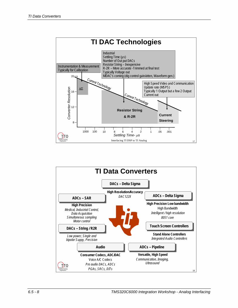
TI DAC Technologies
Settling Time- μs
20
16
12
8
Current Steering
Resistor String
& R-2R
ΔΣ
Con
verte
r Res
olut
ion
6810 4 2 1 .05 .0011001000
Current Technology
High Speed Video and CommunicationUpdate rate (MSPS)Typically 1 Output but a few 2 OutputCurrent out
IndustrialSettling Time (µs)Number of Out put DACsResistor String – InexpensiveR-2R – More accurate -Trimmed at final test Typically Voltage outMDAC’s coming (dig control gain/atten, Waveform gen.)
Instrumentation & MeasurementTypically for Calibration
Current Technology
Technical TrainingOrganization
T TO17
DACs – Delta SigmaDACs – Delta Sigma
High Resolution/AccuracyDAC122X
Touch Screen ControllersTouch Screen Controllers
Stand Alone Controllers Integrated Audio Controllers
TI Data Converters
High Precision Low bandwidthHigh Bandwidth
Intelligent / high resolution8051 core
ADCs – Delta SigmaADCs – Delta Sigma
High PrecisionMedical, Industrial Control,
Data Acquisition Simultaneous sampling
Motor control
ADCs – SARADCs – SAR
Versatile, High Speed Communication, Imaging,
Ultrasound
ADCs – PipelineADCs – Pipeline
Low power, Single and bipolar Suppy, Precision
DACs – String / R2RDACs – String / R2R
Consumer Codecs, ADC/DACVoice A/C Codecs
Pro audio DACs, ADCs PGAs, SRCs, DITs
AudioAudio
Technical TrainingOrganization
T TO18
6.5 - 8 TMS320C6000 Integration Workshop - Analog Interfacing
Selecting an Example ADC
Selecting an Example ADC
Interfacing TI DSP to TI Analog
Go to “ti.com” with your browserIn the Products box, hover over Analog and Mixed Signal & selectData Converters In the Data Converters Home box in the upper left, hover over Find a Device and select Parametric SearchPick a bit resolution and sample rate, and a list of suitable devices are displayed, comparing numerous additional parameters, including:Device name Status Resolution Sample RateArchitecture # Channels SE vs Diff’l Pwr Consumpt’nSINAD SNR SFDR ENOBVoltage ranges Bandwidth # supplies Pins/Pkg
Selecting a Device
Technical TrainingOrganization
T TO20
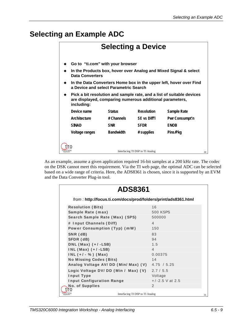
As an example, assume a given application required 16-bit samples at a 200 kHz rate. The codec on the DSK cannot meet this requirement. Via the TI web page, the optimal ADC can be selected based on a wide range of criteria. Here, the ADS8361 is chosen, since it is supported by an EVM and the Data Converter Plug-in tool.
Interfacing TI DSP to TI Analog
ADS8361from : http://focus.ti.com/docs/prod/folders/print/ads8361.html
2 No. of Supplies +/-2.5 V at 2.5 Input Configuration Range Voltage Input Type 2.7 / 5.5Logic Voltage DV/DD (Min / Max) (V)
4.75 / 5.25Analog Voltage AV/DD (Min/Max) (V) 14 No Missing Codes (Bits) 0.00375 INL (+/- %) (Max) 4 INL (Max) (+/-LSB) 1.5 DNL (Max) (+/-LSB) 94 SFDR (dB) 83 SNR (dB)
150 Power Consumption (Typ) (mW) 4 # Input Channels (Diff)
500000 Search Sample Rate (Max) (SPS) 500 KSPS Sample Rate (max) 16 Resolution (Bits)
Technical TrainingOrganization
T TO21
TMS320C6000 Integration Workshop - Analog Interfacing 6.5 - 9
Development Challenges
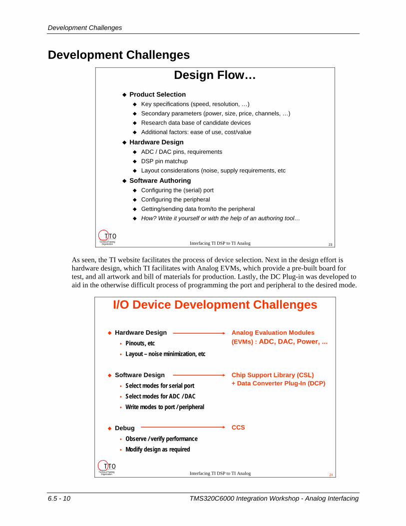
Development Challenges
Interfacing TI DSP to TI Analog
Design Flow…Product Selection
Key specifications (speed, resolution, …)Secondary parameters (power, size, price, channels, …)Research data base of candidate devicesAdditional factors: ease of use, cost/value
Hardware DesignADC / DAC pins, requirementsDSP pin matchupLayout considerations (noise, supply requirements, etc
Software AuthoringConfiguring the (serial) portConfiguring the peripheralGetting/sending data from/to the peripheralHow? Write it yourself or with the help of an authoring tool…
Technical TrainingOrganization
T TO23
As seen, the TI website facilitates the process of device selection. Next in the design effort is hardware design, which TI facilitates with Analog EVMs, which provide a pre-built board for test, and all artwork and bill of materials for production. Lastly, the DC Plug-in was developed to aid in the otherwise difficult process of programming the port and peripheral to the desired mode.
Interfacing TI DSP to TI Analog
I/O Device Development Challenges
Hardware DesignPinouts, etcLayout – noise minimization, etc
Software DesignSelect modes for serial portSelect modes for ADC / DACWrite modes to port / peripheral
DebugObserve / verify performanceModify design as required
Analog Evaluation Modules(EVMs) : ADC, DAC, Power, ...
Chip Support Library (CSL)+ Data Converter Plug-In (DCP)
CCS
Technical TrainingOrganization
T TO24
6.5 - 10 TMS320C6000 Integration Workshop - Analog Interfacing
Analog EVMs
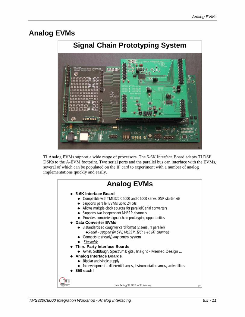
Analog EVMs
Interfacing TI DSP to TI Analog
Signal Chain Prototyping System
53
TI Analog EVMs support a wide range of processors. The 5-6K Interface Board adapts TI DSP DSKs to the A-EVM footprint. Two serial ports and the parallel bus can interface with the EVMs, several of which can be populated on the IF card to experiment with a number of analog implementations quickly and easily.
Interfacing TI DSP to TI Analog
Analog EVMs5-6K Interface Board
Compatible with TMS320 C5000 and C6000 series DSP starter kitsSupports parallel EVM’s up to 24 bitsAllows multiple clock sources for parallel/Serial converters Supports two independent McBSP channelsProvides complete signal chain prototyping opportunities
Data Converter EVMs3 standardized daughter card format (2 serial, 1 parallel)
Serial – support for SPI, McBSP, I2C; 1-16 I/O channelsConnects to (nearly) any control systemStackable
Third Party Interface BoardsAvnet, SoftBaugh, Spectrum Digital, Insight - Memec Design …
Analog Interface BoardsBipolar and single supplyIn development – differential amps, instrumentation amps, active filters
$50 each!
Technical TrainingOrganization
T TO27
TMS320C6000 Integration Workshop - Analog Interfacing 6.5 - 11

Data Converter Plug-In
Data Converter Plug-In
Interfacing TI DSP to TI Analog
Data Converter Plug-InAllows rapid application development
Automatically generates required DSP source code
Removes the necessity to learn the converter “bit by bit”
Includes help for device features
Fully integrated into Code Composer Studio (2, 5, and 6K)
29
The Data Converter Plug-in (DCP) greatly reduces the time and effort required to program a wide variety of DSP ports and analog peripherals. The plug-in can be downloaded (free of charge) from: http://www.ti.com/sc/dcplug-in.
Interfacing TI DSP to TI Analog
Launching the Data Converter Plug-In
30
6.5 - 12 TMS320C6000 Integration Workshop - Analog Interfacing
Data Converter Plug-In
Interfacing TI DSP to TI Analog
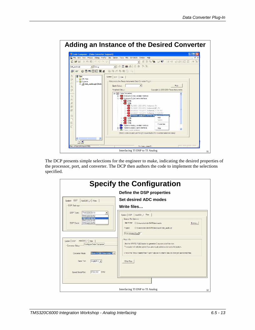
Adding an Instance of the Desired Converter
31
The DCP presents simple selections for the engineer to make, indicating the desired properties of the processor, port, and converter. The DCP then authors the code to implement the selections specified.
Interfacing TI DSP to TI Analog
Specify the ConfigurationDefine the DSP properties Set desired ADC modesWrite files…
32
TMS320C6000 Integration Workshop - Analog Interfacing 6.5 - 13
Data Converter Plug-In
Interfacing TI DSP to TI Analog
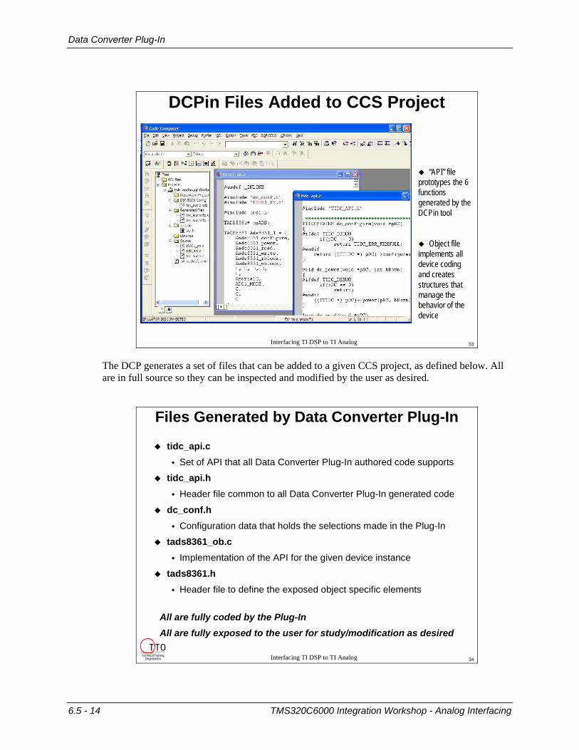
DCPin Files Added to CCS Project
“API” file prototypes the 6 functions generated by the DCPin tool
Object file implements all device coding and creates structures that manage the behavior of the device
33
The DCP generates a set of files that can be added to a given CCS project, as defined below. All are in full source so they can be inspected and modified by the user as desired.
Interfacing TI DSP to TI Analog
Files Generated by Data Converter Plug-In
tidc_api.cSet of API that all Data Converter Plug-In authored code supports
tidc_api.hHeader file common to all Data Converter Plug-In generated code
dc_conf.hConfiguration data that holds the selections made in the Plug-In
tads8361_ob.cImplementation of the API for the given device instance
tads8361.hHeader file to define the exposed object specific elements
All are fully coded by the Plug-InAll are fully exposed to the user for study/modification as desired
Technical TrainingOrganization
T TO34
6.5 - 14 TMS320C6000 Integration Workshop - Analog Interfacing
Data Converter Plug-In
Interfacing TI DSP to TI Analog
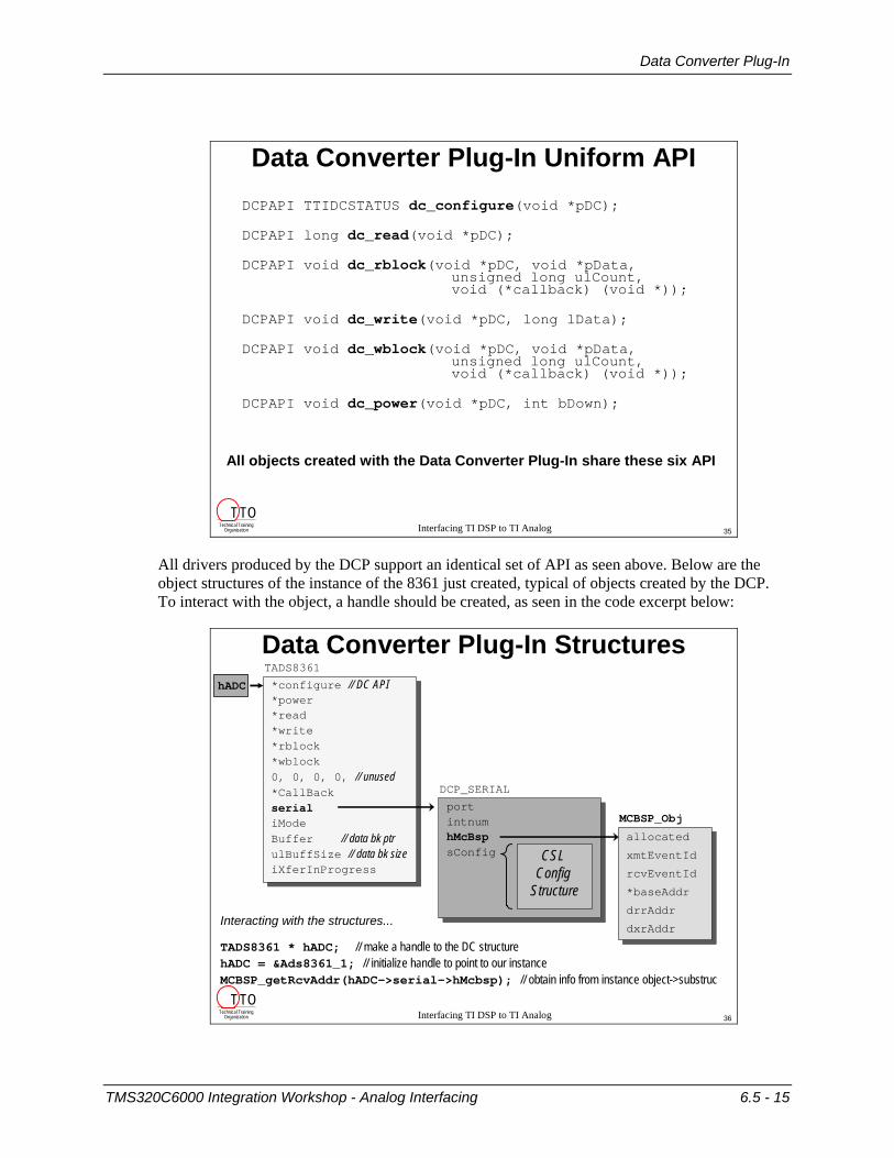
Data Converter Plug-In Uniform APIDCPAPI TTIDCSTATUS dc_configure(void *pDC);
DCPAPI long dc_read(void *pDC);
DCPAPI void dc_rblock(void *pDC, void *pData,unsigned long ulCount,void (*callback) (void *));
DCPAPI void dc_write(void *pDC, long lData);
DCPAPI void dc_wblock(void *pDC, void *pData,unsigned long ulCount, void (*callback) (void *));
DCPAPI void dc_power(void *pDC, int bDown);
All objects created with the Data Converter Plug-In share these six API
Technical TrainingOrganization
T TO35
All drivers produced by the DCP support an identical set of API as seen above. Below are the object structures of the instance of the 8361 just created, typical of objects created by the DCP. To interact with the object, a handle should be created, as seen in the code excerpt below:
Interfacing TI DSP to TI Analog
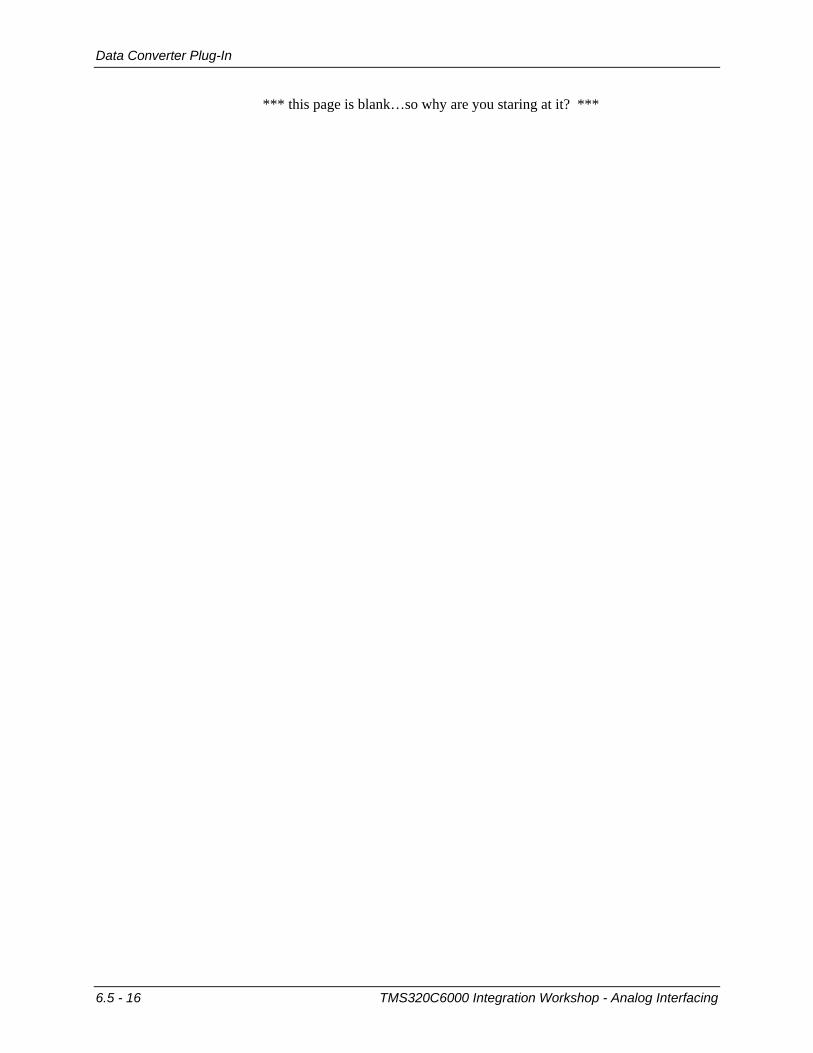
Data Converter Plug-In StructuresTADS8361
*configure // DC API*power*read*write*rblock*wblock0, 0, 0, 0, // unused*CallBackserialiModeBuffer // data bk ptrulBuffSize // data bk sizeiXferInProgress
DCP_SERIAL
portintnumhMcBspsConfig
MCBSP_Obj
allocated
xmtEventId
rcvEventId
*baseAddr
drrAddr
dxrAddr
hADC
CSL Config
Structure
Interacting with the structures...
TADS8361 * hADC; // make a handle to the DC structurehADC = &Ads8361_1; // initialize handle to point to our instanceMCBSP_getRcvAddr(hADC->serial->hMcbsp); // obtain info from instance object->substruc
Technical TrainingOrganization
T TO36
TMS320C6000 Integration Workshop - Analog Interfacing 6.5 - 15
Data Converter Plug-In
*** this page is blank…so why are you staring at it? ***
6.5 - 16 TMS320C6000 Integration Workshop - Analog Interfacing
Lab 6.5: Analog Interfacing
Lab 6.5: Analog Interfacing In this lab, all the steps described in the lecture will be performed. A few minutes will be spent looking over the TI analog website resources to locate a device that meets a given specification. Once selected, EVMs that contain the selected device will be assembled into a hardware test platform. Next, the Data Converter Plug-in (DCP) will be used to generate the code to initialize the serial port that connects to the ADC, and the API to collect data from the converter. The DCP generated code will then be integrated into the prior lab in this workshop, run and the results analyzed. This lab serves as an example of the steps taken in a real-world design, and may serve as a helpful ‘recipe’ in your future development work.
A. Selecting the optimal device Often, the first step in a design is device selection. This process is facilitated with the TI website (if you don’t have web access, skip to part B):
1. Launch Internet Explorer.
From a PC that has an on-line connection, launch Explorer and go to www.ti.com.
2. Select Data Converters.
In the Products box, hover over Analog and Mixed Signal & select Data Converters.
3. Select Parametric Search and perform a Quick Search.
In the Data Converters Home box in the upper left, hover over Find a Device and select Parametric Search.
In the central box, under Data Converters, click on the Quick Search link.
4. Select the parameters.
Select the following parameters in the table:
• In the table, click on the intersection of 16 bits and 100 to 500kSPS.
• Under # Input Channels (Diff), select 4.
• Of the three devices shown, the 8361 is the one which will operate to 200KSPS; click on the 8361 link to learn more about this device
5. View other available information, the close the browser.
Scan the information available on this page and note the many links to learn more about the device, including data sheets, app notes, and so forth. Scroll to the bottom of the page, and note the links for the ADS8361 Evaluation Module and the DCP (DCPFREETOOL). If desired, click on either to view more about them.
When satisfied, close the browser and continue with the next part of the lab…
TMS320C6000 Integration Workshop - Analog Interfacing 6.5 - 17
Lab 6.5: Analog Interfacing
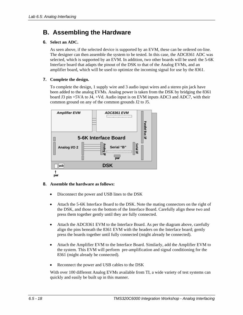
B. Assembling the Hardware 6. Select an ADC.
As seen above, if the selected device is supported by an EVM, these can be ordered on-line. The designer can then assemble the system to be tested. In this case, the ADC8361 ADC was selected, which is supported by an EVM. In addition, two other boards will be used: the 5-6K Interface board that adapts the pinout of the DSK to that of the Analog EVMs, and an amplifier board, which will be used to optimize the incoming signal for use by the 8361.
7. Complete the design.
To complete the design, 1 supply wire and 3 audio input wires and a stereo pin jack have been added to the analog EVMs. Analog power is taken from the DSK by bridging the 8361 board J3 pin +5VA to J4, +Vd. Audio input is on EVM inputs ADC3 and ADC7, with their common ground on any of the common grounds J2 to J5.
DSK
pwr
usb
5-6K Interface Board
Parallel Bus I/F
Serial “A”
Serial “B”
Analog I/O 1
Analog I/O 2
ADC8361 EVMAmplifier EVM
Serial I/F
Analog I/F
pwr
8. Assemble the hardware as follows:
• Disconnect the power and USB lines to the DSK
• Attach the 5-6K Interface Board to the DSK. Note the mating connectors on the right of the DSK, and those on the bottom of the Interface Board. Carefully align these two and press them together gently until they are fully connected.
• Attach the ADC8361 EVM to the Interface Board. As per the diagram above, carefully align the pins beneath the 8361 EVM with the headers on the Interface board; gently press the boards together until fully connected (might already be connected).
• Attach the Amplifier EVM to the Interface Board. Similarly, add the Amplifier EVM to the system. This EVM will perform pre-amplification and signal conditioning for the 8361 (might already be connected).
• Reconnect the power and USB cables to the DSK
With over 100 different Analog EVMs available from TI, a wide variety of test systems can quickly and easily be built up in this manner.
6.5 - 18 TMS320C6000 Integration Workshop - Analog Interfacing

Lab 6.5: Analog Interfacing
C. Using the Data Converter Plug-in Now that a hardware system has been assembled, the next goal will be to create code to put
the serial port in the correct mode of operation to communicate with the selected converter, and – if necessary – send commands to the converter to put it in the desired operating mode. Normally, this tends to be a tedious and confusing process, since there are a number of choices to be made, many of which may be outside the experience of most programmers and all of which take time to implement and verify. In addition, the need to carefully match up all these options with the particular bit-field of a specific port control register is often an area where mistakes get made and a lot of time is lost in debug and revision.
Given the above, TI created the Data Converter Plug-in (DCP) tool, which allows the user to specify a few key options, from which the wizard will then author the code automatically – greatly reducing coding effort and all but eliminating the need for debug and revision pains. The plug-in may be downloaded at no cost, and its use and the code generated carry no license or royalty fees.
9. If open, close CCS.
10. Download the DCP and add this plug-in to CCS.
Using Internet Explorer, download the most recent version of the DCP from: http://www.ti.com/sc/dcplug-in. It is likely that the DCP is already downloaded and installed. Check with your instructor for more information. If so, skip to step #12.
Follow the prompts to add this plug-in to CCS. Note: a number of plug-ins are available for CCS which can offer a range of abilities to the programmer – see the TI website to learn more about this in the future.
11. Run CCS, open audioapp.pjt and verify current code operation.
Open and maximize CCS. Open audioapp.pjt. Rebuild all, download and verify the audio plays as in the prior lab. Halt the code once this validated starting point is verified.
12. Run the DCP via this menu selection:
Tools Data Converter Support
13. Select DSP type and speed.
Click on the DSP tab and select the DSP type present on your DSK and its clock frequency. You can verify the DSP speed in the .cdb file under System Global Settings.
14. Add an instance for the ADS8361.
Click on the DCP’s System tab. Under the A to D serial interface folder, 16 Bit sub-folder, right click on the ADS8361 and Add an instance. Note the new tab that appears for the instance just created.
TMS320C6000 Integration Workshop - Analog Interfacing 6.5 - 19
Lab 6.5: Analog Interfacing
15. Verify mode and serial port selection.
Under the Ads8361_1 tab, verify that Mode II and McBSP 0 are selected. For this lab, the port speed selected by the DCP can be left as is.
16. Show the created files.
Under the DCP’s Files tab, select the option to show the created files and click on Write Files.
17. Tile the files.
Tile the files in the main CCS window. Close the DCP and look over the files created to your satisfaction. Close the windows when finished.
D. Integrating the New Code to the Existing Project Having created the files that will configure and interact with the serial port and converter, the
next step is to add the C source files to the project and make a few changes to the original lab 6 code to use the new code and perform a few other modifications as outlined below.
18. Note the added DCP Files.
Note that upon creation of the DCP files, that two C files (tidc_api.c and t8361_ob.c) were added to the project automatically.
19. Add include files and configure the ADS8361.
Open main.c and make the following additions to the list of inclusions at the beginning of the file:
#include "dc_conf.h" #include "t8361_fn.h“
Then add the following statement immediately after the initialization of the McBSP:
dc_configure(&Ads8361_1);
Usually, the location of the dc_configure API would be less critical, but here both serial ports were used to interact with the on-board codec – one to send/receive data, and the other to set the codec’s mode of operations.
20. Close the serial port and set a bit on the DSK’s FPGA.
Open mcbsp.c and add the following two lines just prior to the closing brace:
MCBSP_close(hMcbspControl); *((unsigned char*)0x90080006) |= 0x01;
The first line closes the port so that the CSL manager can use (open) it later with the DCP’s generated code. The second line sets a bit on the DSK’s FPGA routing Serial Port 0 pins to the external peripheral interface leading to the 8361 EVM. While the use of BSL (the Board Support Library) would have also worked, this implementation suffices here because it is only a single line.
6.5 - 20 TMS320C6000 Integration Workshop - Analog Interfacing
Lab 6.5: Analog Interfacing
21. Modify the EDMA to recognize the synchronization signals.
Since lab6 uses the EDMA to read from the serial port, the final step is to modify the EDMA to recognize synch signals and read data from serial port 0 instead of the currently specified ‘data’ port.
Open edma.c and find the line starting with hEdmaRcv = and change the first argument to:
EDMA_CHA_REVT0 To change the read address, look for the line that begins with gEdmaConfigRcv.src and change its argument from:
hMcbspData to hADC->serial->hMcbsp.
To use the above argument, the handle must be declared and initialized at the start of the initEdma function by adding the following two lines after the function’s opening brace:
TADS8361 * hADC; hADC = &Ads8361_1;
To make the data type above known to this file, add the following line to the inclusions in:
#include "t8361_fn.h"
Time permitting, peruse the DCP files to note the declaration of the TADS8361 type and the creation of the structure at address Ads8361_1
22. Finally, save the modified files and rebuild the project. A handful of warnings will be generated (the libraries are being revised to eliminate them). Just ignore the warning(s).
E. Load & run the new code, observe performance 23. Run the new code.
Disconnect the audio input cable from the LINE IN on the DSK and connect it to the stereo jack on the left side of the 5K-6K board underneath the op-amp board. Download the newly built code and run as before. Is the music being passed to the speaker as before? If not, look over the setup and see if anything is amiss. If a hint is required, ask the instructor.
24. Is the sound quality ok?
Consider the sound quality – is it the same as before? Before reading on, note any ideas you may have on what may be happening: ____________________________________________ ___________________________________________________________________________
TMS320C6000 Integration Workshop - Analog Interfacing 6.5 - 21
Lab 6.5: Analog Interfacing
25. Channel ID problem explained.
One subtle problem that yields a gross error easily observed on an oscilloscope is that the 8361, a four channel device, tags the channel ID to the MSBs of each data sample. Therefore, there is a high frequency / high amplitude error being passed into the system with the presence of these extra bits. Note any suggestions you can think of for how to remedy this problem before reading on: ___________________________________________________ ___________________________________________________________________________
Normally, these leading ID bits would likely be helpful to the user to assure the data is being correctly routed. Software could verify and then be mask off the extra bits with a simple AND operation before being used as proper data. The stripping of the channel bits could be part of the device driver or an initial part of the algorithm that consumes the data from the ADC. In either case, the effort and overhead are quite minimal.
Another way to solve the leading ID bit problem is to program the serial port to wait a few clock cycles from the frame synch before reading in data, thus ignoring the ID bits and only collecting the data bits themselves. This solution is outlined in the optional step that follows, and involves modifying the contents of a file built by the DCP. This sort of thing is actually a reasonable and normal option for ‘fine tuning’ the port behavior when optimizing the system.
26. Optional for DSK6416 Users Only: modify code by hand to resolve the leading ID bit problem • Open DCP file t8361_ob.c and make the changes below in the configure API:
pADS->serial->sConfig.rcr = 0x00000060; – change mask to 0x00010140 pADS->serial->sConfig.pcr = 0x00000504; – change mask to 0x00000A06 pADS->serial->sConfig.srgr =0x30141300 | ... – change mask to 0x30140232
• Rebuild, download, run, verify improved performance
Is the sound quality fully restored? What could be the remaining problem? Note your ideas here: _____________________________________________________________________ ___________________________________________________________________________
One other note – the new ADC uses a different sampling rate then the DAC side of the AIC on the DSK. It’s not an optimal solution, but provides the user with a method of checking out different codecs or discrete devices in hardware without worrying too much about the software side.
27. Copy project to preserve your solution.
Using Windows Explorer, copy the contents of:
c:\iw6000\labs\audioapp\*.* TO c:\iw6000\labs\lab65
6.5 - 22 TMS320C6000 Integration Workshop - Analog Interfacing

Conclusions
Conclusions
Interfacing TI DSP to TI Analog
Conclusions on TI DSP + TI Analog …
TI offers a large number of low cost analog EVMs to allow developers to ‘snap together’a signal chain for ultra-fast test and debug of proposed componentsTI provides CSL and Data Converter Plug-In to vastly reduce the effort in getting a DSP to talk to ports and peripheralsGetting to ‘signs of life’ result is now a matter of minutes instead of days/weeksFinal tuning will sometimes be required, but amounts to a manageable effort with a device already easily observed, rather than ‘groping in the dark’ as often was the case otherwise
Technical TrainingOrganization
T TO43
TMS320C6000 Integration Workshop - Analog Interfacing 6.5 - 23
Additional Information
Additional Information
Interfacing TI DSP to TI Analog
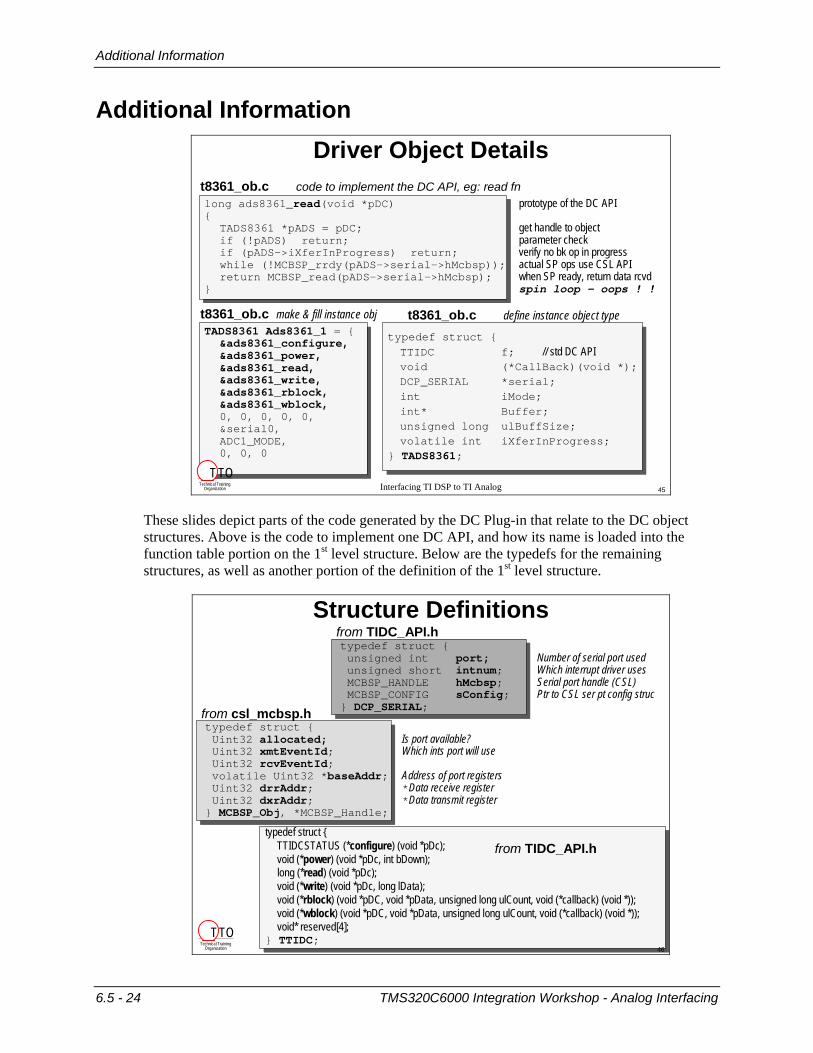
Driver Object Details
long ads8361_read(void *pDC) prototype of the DC API {
TADS8361 *pADS = pDC; get handle to objectif (!pADS) return; parameter checkif (pADS->iXferInProgress) return; verify no bk op in progresswhile (!MCBSP_rrdy(pADS->serial->hMcbsp)); actual SP ops use CSL APIreturn MCBSP_read(pADS->serial->hMcbsp); when SP ready, return data rcvd
} spin loop – oops ! !
t8361_ob.c code to implement the DC API, eg: read fn
TADS8361 Ads8361_1 = {&ads8361_configure,&ads8361_power,&ads8361_read,&ads8361_write,&ads8361_rblock,&ads8361_wblock,0, 0, 0, 0, 0, &serial0, ADC1_MODE,0, 0, 0
};
t8361_ob.c make & fill instance obj
typedef struct {TTIDC f; // std DC APIvoid (*CallBack)(void *);DCP_SERIAL *serial;int iMode;int* Buffer;unsigned long ulBuffSize;volatile int iXferInProgress;
} TADS8361;
t8361_ob.c define instance object type
Technical TrainingOrganization
T TO45
These slides depict parts of the code generated by the DC Plug-in that relate to the DC object structures. Above is the code to implement one DC API, and how its name is loaded into the function table portion on the 1st level structure. Below are the typedefs for the remaining structures, as well as another portion of the definition of the 1st level structure.
Interfacing TI DSP to TI Analog
Structure Definitionstypedef struct {unsigned int port; Number of serial port usedunsigned short intnum; Which interrupt driver usesMCBSP_HANDLE hMcbsp; Serial port handle (CSL)MCBSP_CONFIG sConfig; Ptr to CSL ser pt config struc
} DCP_SERIAL;
typedef struct {Uint32 allocated; Is port available?Uint32 xmtEventId; Which ints port will use Uint32 rcvEventId;volatile Uint32 *baseAddr; Address of port registersUint32 drrAddr; *Data receive registerUint32 dxrAddr; *Data transmit register
} MCBSP_Obj, *MCBSP_Handle;
from TIDC_API.h
from csl_mcbsp.h
typedef struct { TTIDCSTATUS (*configure) (void *pDc);void (*power) (void *pDc, int bDown);long (*read) (void *pDc);void (*write) (void *pDc, long lData); void (*rblock) (void *pDC, void *pData, unsigned long ulCount, void (*callback) (void *));void (*wblock) (void *pDC, void *pData, unsigned long ulCount, void (*callback) (void *));void* reserved[4];
} TTIDC;
from TIDC_API.h
Technical TrainingOrganization
T TO46
6.5 - 24 TMS320C6000 Integration Workshop - Analog Interfacing

Additional Information
Interfacing TI DSP to TI Analog
Analog Design Tools in DevelopmentOpAmpPro - Input data selects IC
Input data contains transfer functionInput data selects the appropriate circuitProgram enables adjustment resistor & worst case calculationsOp Amp Pro selects IC by analyzing applications and input dataCalculates error due to external component & IC tolerances
Tina-TI Spice Simulation ProgramTo be offered free on www.ti.comUses TI’s SPICE macromodelsAllows general spice circuit simulationAnalysisCircuit optimization
Technical TrainingOrganization
T TO47
New analog design tools are in development at TI, to be available on the website soon. Examples include the OpAmpPro and Tina, as described above. The diagram below demonstrates the kind of circuit TINA can help users generate.
Interfacing TI DSP to TI Analog
Example Analysis Circuit
Vcommon-mode
Vsample
Vinput
+Vsample
+ Vinput
C4
100p
C3 100p
Vout
Vreference 5
R5 40k
+Vcommon-mode
C2 25p
C1
1n
R6 100
R4
40k
V1 5
R3 100k
R2 100k R1 20k
-
+ + U1 OPA364ADS8325 16-bit1/2 lsb = 38uVtaq < 1.875uSCin = 20pf
ADS7829 12-bit1/2 lsb = 610uVtaq < 750nSCin = 25pF
ADS Reference
+/- 10V Signal Conditioning for 5V ADC's
"Flywheel"Conditioning Network analog input
Technical TrainingOrganization
T TO48
TMS320C6000 Integration Workshop - Analog Interfacing 6.5 - 25
Additional Information
*** this page is not supposed to be blank…something is missing…really ***
6.5 - 26 TMS320C6000 Integration Workshop - Analog Interfacing


![· Transducer Interfacing Handbook. ... Dan Sheingold [dan.sheingold@analog.com] ANALOG ICs POWER DIGITAL TVs At midnight on February 17, 2009, most commercial analog TV broadcasts—long](https://img.pdfslide.net/doc/110x75/5c8e7ab609d3f270788d041e/-transducer-interfacing-handbook-dan-sheingold-dansheingold-analog.jpg)