Embed Size (px)
Citation preview

Sensors Worldwide
™
BTL5-A/C/E/G_-M____-R-S32/KA__
Micropulse Linear Transducer
Analog Output/Low-Profile Housing
Technical Description / User’s Guide

™

™
28 0711 30 0762 32 0813 36 0914 40 1016
inches mm 15 0381 16 0407 18 0457 20 0508 22 0560 24 0610 26 0661
Rugged,CompactRod Style
Compact,bolt-inRod Style
Rod Style
Explosion-proofRod Style
Balluff - Linear Transducer
Generation 5
Output Type
Supply Voltage1 = 24 Vdc ±20%2 = ±15 Vdc ±2% (Not available for S, T or H outputs)
Analog Output OperationVoltage type (Output type A, B & G)1 = User selectable rising or fallingCurrent type (Output type C & E)0 = Minimum output at connector end (rising towards opposite end)7= Maximum output at connector end (falling towards opposite end)
Normal Stroke Length
Housing TypeP = Standard Profile Housing
Connection Type
S 3 2
K A 0 5
= 8-pin quick disconnect metal connector
= Cable out (5m standard; specify length in meters)
K A 0 5
=====
0 to 10Vdc-5 to +5Vdc0 to 20 mA4 to 20 mA-10 to +10 Vdc
ABCEG
0 3 0 5 = 305mm active stroke
1 2 3 4 5 6 7 8 9 10 11 12 13 14 15 16 17 18 19 20 21 22
B T L - 5 - A 1 1 - M 0 3 0 5 - R - S 3 2
Standard Stroke Lengths (consult factory for additional lengths)
inches mm 148 3759 156 3962
Electrical Stroke
inches mm 2 0051 3 0077 4 0102 5 0127 6 0152 7 0178 8 0203 9 0230 10 0254 11 0280 12 0305 13 0330
inches mm 42 1067 48 1220 50 1270 60 1524 70 1778 80 2032 90 2286 100 2540 110 2794 120 3048 130 3302 142 3606

1-800-543-8390 · WWW.BALLUFF.COM2
BTL5-A/C/E/G_ _-M/U_ _ _ _-R-S 32/KA_ _Micropulse Linear Position TransducerAnalog Output/Low-Profile Housing ™
1 Safety Advisory .............. 21.1 Proper application ........... 21.2 Qualified personnel ......... 21.3 Use and inspection ......... 21.4 Scope .............................. 22 Function and
Characteristics .............. 32.1 Characteristics ................ 32.2 Function .......................... 32.3 Available stroke lengths
and magnets ................... 33 Installation ..................... 33.1 Transducer installation .... 33.2 Floating magnets ............ 43.3 Captive magnets ............. 54 Wiring ............................. 65 Startup ........................... 7
Contents
5.1 Check connections ......... 75.2 Turning on the system ..... 75.3 Check output values ....... 75.4 Check functionality ......... 75.5 Fault conditions .............. 75.6 Noise elimination ............. 76 Versions (indicated
on part label) .................. 77 Technical Data ............... 87.1 Dimensions, weights,
ambient conditions ......... 87.2 Supply voltage (external) 87.3 Outputs ........................... 87.4 Connection to processor 87.5 Included in shipment ...... 87.6 Magnets (order separately)87.7 Accessories (optional) ..... 8
1 Safety Advisory
Read this manual before installing and operating the MicropulseTransducer.
1.1 Proper application
The BTL5 Micropulse transducer is intended to be installed in amachine or system. Together with a controller (PLC) or a processor(BTA) it comprises a position measuring system and may only beused for this purpose.
Unauthorized modifications and non-permitted usage will result inthe loss of warranty and liability claims.
1.2 Qualified personnel
This guide is intended for specialized personnel who will perform theinstallation and setup of the system.
1.3 Use and inspection
The relevant safety regulations must be followed when using thetransducer system. In particular, steps must be taken to ensure thatshould the transducer system become defective, no hazards topersons or property can result. This includes the installation ofadditional safety limit switches, emergency shutoff switches andmaintaining the permissible ambient conditions.
1.4 Scope
This guide applies to the model BTL5-A/C/E/G...R... Micropulsetransducer.
An overview of the variousmodels can be found in section 6Versions (indicated on part label)on page 7.
Note: For special versions,which are indicated by an -SU_ _ _ designation in the partnumber, other technical datamay apply (affecting calibra-tion, wiring, dimensions etc.).
The CE Mark verifies thatour products meet therequirements ofEC Directive
89/336/EEC (EMC Directive)
and the EMC Law. Testing in ourEMC Laboratory, which is accred-ited by DATech for TestingElectromagnetic Compatibility, hasconfirmed that Balluff productsmeet the EMC requirements of thefollowing Generic Standards:
•EN 50081-2 (emission)
•EN 61000-6-2 (noise immunity)
Emission tests:RF EmissionEN 55011 Group 1, Class ANoise immunity tests:Static electricity (ESD)EN 61000-4-2 Severity level 3Electromagnetic fields (RFI)EN 61000-4-3 Severity level 3Fast transients (Burst)EN 61000-4-4 Severity level 3SurgeEN 61000-4-5 Severity level 2Line-induced noise induced byhigh-frequency fieldsEN 61000-4-6 Severity level 3Magnetic fieldsEN 61000-4-8 Severity level 4
The following patentshave been granted inconnection with thisproduct:
US Patent 5 923 164Apparatus and Methodfor Automatically Tuningthe Gain of an Amplifier
WWW.BALLUFF.COM · 1-800-543-8390 3
BTL5-A/C/E/G_ _-M/U_ _ _ _-R-S 32/KA_ _Micropulse Linear Position Transducer
Analog Output/ Low-Profile Housing™
2 Function and Characteristics
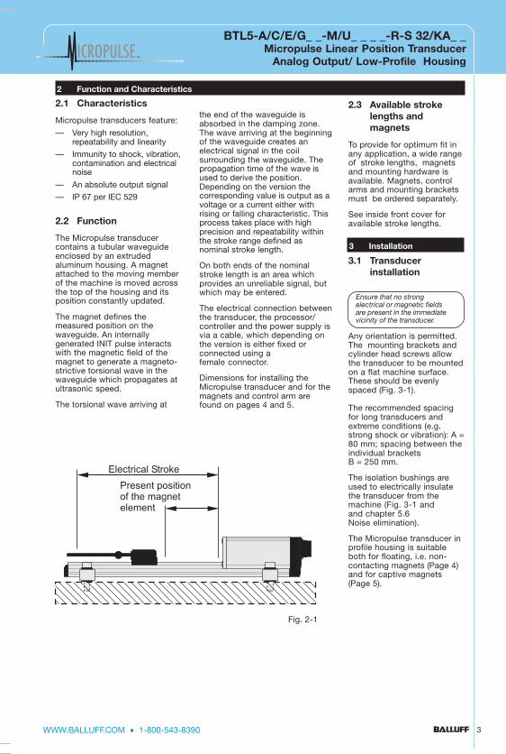
2.1 Characteristics
Micropulse transducers feature:
— Very high resolution,repeatability and linearity
— Immunity to shock, vibration,contamination and electricalnoise
— An absolute output signal
— IP 67 per IEC 529
2.2 Function
The Micropulse transducercontains a tubular waveguideenclosed by an extrudedaluminum housing. A magnetattached to the moving memberof the machine is moved acrossthe top of the housing and itsposition constantly updated.
The magnet defines themeasured position on thewaveguide. An internallygenerated INIT pulse interactswith the magnetic field of themagnet to generate a magneto-strictive torsional wave in thewaveguide which propagates atultrasonic speed.
The torsional wave arriving at
the end of the waveguide isabsorbed in the damping zone.The wave arriving at the beginningof the waveguide creates anelectrical signal in the coilsurrounding the waveguide. Thepropagation time of the wave isused to derive the position.Depending on the version thecorresponding value is output as avoltage or a current either withrising or falling characteristic. Thisprocess takes place with highprecision and repeatability withinthe stroke range defined asnominal stroke length.
On both ends of the nominalstroke length is an area whichprovides an unreliable signal, butwhich may be entered.
The electrical connection betweenthe transducer, the processor/controller and the power supply isvia a cable, which depending onthe version is either fixed orconnected using afemale connector.
Dimensions for installing theMicropulse transducer and for themagnets and control arm arefound on pages 4 and 5.
2.3 Available strokelengths andmagnets
To provide for optimum fit inany application, a wide rangeof stroke lengths, magnetsand mounting hardware isavailable. Magnets, controlarms and mounting bracketsmust be ordered separately.
See inside front cover foravailable stroke lengths.
3.1 Transducerinstallation
Any orientation is permitted.The mounting brackets andcylinder head screws allowthe transducer to be mountedon a flat machine surface.These should be evenlyspaced (Fig. 3-1).
The recommended spacingfor long transducers andextreme conditions (e.g.strong shock or vibration): A =80 mm; spacing between theindividual bracketsB = 250 mm.
The isolation bushings areused to electrically insulatethe transducer from themachine (Fig. 3-1 andand chapter 5.6Noise elimination).
The Micropulse transducer inprofile housing is suitableboth for floating, i.e. non-contacting magnets (Page 4)and for captive magnets(Page 5).
3 Installation
Ensure that no strongelectrical or magnetic fieldsare present in the immediatevicinity of the transducer.
Electrical Stroke
Present positionof the magnetelement
Fig. 2-1

1-800-543-8390 · WWW.BALLUFF.COM4
BTL5-A/C/E/G_ _-M/U_ _ _ _-R-S 32/KA_ _Micropulse Linear Position TransducerAnalog Output/Low-Profile Housing ™
3 Installation (cont.)
3.2 Floating magnets
The floating magnet (Figs. 3-2to 3-4) is attached to themoving member of the machineusing non-magnetizable screws(brass, aluminum). To ensurethe accuracy of the transducersystem, the moving membermust carry the magnet on atrack parallel tothe transducer.
The following table providesfigures in [mm] for the spacingwhich must be maintainedbetween magnet andtransducer and for thepermissible center offset:
Fig. 3-2: BTL5-P-3800-2 magnet Fig. 3-3: BTL5-P-5500-2 magnet Fig. 3-4: BTL5-P-4500-1electromagnet (24 V/100 mA)
Magnet type Distance" D "
Offset" C "
BTL5-P-3800-2 0.1 ... 4 ± 2
BTL5-P-5500-2 5 ... 15 ± 15
BTL5-P-4500-1 0.1 ... 2 ± 2
BTL5-P-4500-1 magnet, specialfeatures: Multiple magnets onthe same transducer can beturned on and off individually(PLC control signal).
The stroke range is offset 4mm towards the BTLconnector/cable (Fig. 3-4).
20
914
D
38
28
C
50
68
28
+4
Ø4.2
20
D
50
68
15
40
+10
28
55
45
C
Ø8 x 3.2 deep c-boreØ4.221
16.5
40
D
50
68
36
+2
45
25
C
Ø4.2
28
15
25
7.5
M5 x 8
50
68
1
12
46
32
15M5x22 ISO 4762
105
9570 Nominal stroke
5
35
Fig 3-1: Transducer BTL5...R Dimensions
Ensure that thedistance E betweenparts made ofmagnetizable materialand the
BTL5-P-5500-2 magnet is atleast 12 mm (Fig. 3-3).
R
R
R

WWW.BALLUFF.COM · 1-800-543-8390 5
BTL5-A/C/E/G_ _-M/U_ _ _ _-R-S 32/KA_ _Micropulse Linear Position Transducer
Analog Output/ Low-Profile Housing™
3 Installation (cont.)
3.3 Captive magnets
Lateral forces are to be avoidedwhen using captive magnets(Figs. 3-6 thru 3-8). Connectionsare required here which permitthe corresponding degree offreedom with respect to thedirection of movement of themagnet along the
stroke range. It is assumed thatthe BTL5-F-2814-1S magnet isconnected to the machinemember using a connectingrod. The BTL2-GS08...Aconnecting rod (Fig. 3-9) isavailable as an accessory(please indicate length LSwhen ordering).
Ball joint "B" DIN 71805,rotates horizontally (part ofBTL5-F-2814-1S) magnet)
Fig. 3-9: BTL2-GS08-_ _ _ _-Aconnecting rod
Swivel eye DIN 648
Jam nut DIN 934 M5
08
27 3
5
50
68
28
18
15
.523
.5
40.5 21
M5
29 3
7
50
68
28
18
15.523.5
40.5 21
M5
31
24
50
68
40
18°−18°1
4.5
70.5
40
14
.5 23
±18°
24
41
50
68
28
M5 x 10
Fig 3-5: BTL5-M-2814-15 Magnet
Fig 3-7: BTL-F-2814-15 Magnet
Fig 3-6 BTL5-N-2814-15 Magnet
Fig 3-8:BTL-R-2814-15 Magnet

1-800-543-8390 · WWW.BALLUFF.COM6
BTL5-A/C/E/G_ _-M/U_ _ _ _-R-S 32/KA_ _Micropulse Linear Position TransducerAnalog Output/Low-Profile Housing ™
4 Wiring
2 GY
3 PK
5 GN
7 BN
6 BU
8 WH
Analog common
Analog output, falling
Analog output, rising
Analog Voltage24 V (A, B, G)
+24 V
GNDGND
0117a021
1
2
3
4
5
6
7
8
View of matingconnector, wiring side
2 GY
1 YE
7 BN
6 BU
8 WH
Analog commonAnalog output
Analog Current24 V (E, C)
+24 V
GNDGND
0117a023
straightBKS-S 32M-00
right-angleBKS-S 33M-00
Cable entry(PG 9 fitting)
Fig. 4-1: Connector (optional)
When routing the cable betweenthe transducer, controller andpower supply, avoid proximity tohigh voltage lines to preventnoise coupling. Especially criticalis inductive noise caused by ACharmonics (e.g. from phase-control devices), against whichthe cable shield provides onlylimited protection.
Cable length max. 20 m; Ø 6 to8 mm. Longer lengths may beused if construction, shieldingand routing are such that externalnoise fields will have no effect onsignal integrity.
Note the following when makingelectrical connections:
System and control cabinet mustbe at the sameground potential.
To ensureelectromagnetic
compatibility (EMC), which Balluffverifies by the CE Marking, thefollowing points must bestrictly observed.
BTL transducer and theprocessor/control must beconnected using shielded cable.
Shielding: Copper filamentbraided, 80% coverage.
The shield must be tied to theconnector housing in the BKSconnector (Fig. 4-1); seeinstructions accompanying the connector.
In the cable version the cableshield is connected to thehousing in the PG fitting.
The cable shield must begrounded on the control side, i.e.,connected to theprotection ground.
Pin assignments can be foundinthe illustration above .Connections on the controllerside may vary according to thecontroller and configuration used.
Fig. 4-2: Pin assignments BKS,connector type BTL
BKS connector,view towardssolder side offemaleBKS-S 32M-00orBKS-S 33M-00
Table 4-1

WWW.BALLUFF.COM · 1-800-543-8390 7
BTL5-A/C/E/G_ _-M/U_ _ _ _-R-S 32/KA_ _Micropulse Linear Position Transducer
Analog Output/ Low-Profile Housing™
4 Wiring (cont.)
Fig. 4-3: BTL5-E10...KA _ _ with processor card/controller, wiring example
5 Startup
5.1 Check connections
Although the connections arepolarity reversal protected,components can be damagedby improper connections andovervoltage. Before you applypower, check theconnections carefully.
5.2 Turning on the system
Note that the system mayexecute uncontrolledmovements when first turned onor when the transducer is part ofa closed-loop system whoseparameters have not yet beenset. Therefore make sure that nohazards could result fromthese situations.
If there is no magnet in thestroke range, the integratedfunction monitor provides thefollowing defined output signals:
Voltage output 10 Vincreasing decreasingVA > 10 V < 0 V
Current output 20 mAincreasing decreasingIA > 20 mA 0 mA for BTL5-C...IA > 20 mA < 4 mA for BTL5-E...
5.3 Check output values
After replacing or repairing atransducer, it is advisable to verify thevalues for the start and end positionof the magnet in manual mode. Ifvalues other* than those presentbefore the replacement or repair arefound, a correction should be made.
* Transducers are subject tomodification or manufacturingtolerances.
5.4 Check functionality
The functionality of the transducersystem and all its associated com
6 Versions (indicated on part label)
Supply voltage 1 = DC 24 V, Electr. connection S32: with connector,
BTL5-A11-M0457-R-S32 KA05: with 5 m cable Profile form factor
Nom. length (4 digits), M = metric in mm
Analog interface: Voltage output A_1 = 10 ... 0 V and 0 ... 10 VG_1 = 10 ... –10 V and –10 ... 10 V
Current output C_0 = 0 ... 20 mA E_0 = 4 ... 20 mAC_7 = 20 ... 0 mA E_7 = 20 ... 4 mA
Mic
rop
ulse
Line
ar T
rans
duc
er
YE
GY
PK
GN
BU
BN
not used
GND
10...0 V
0...10 V
GND
+24 V
pro
cess
or/
cont
rolle
r w
ith a
nalo
gin
putBTL
5-A
11_-
...
ponents should be regularlychecked and recorded.
5.5 Fault conditions
When there is evidence thatthe transducer system is notoperating properly, it should betaken out of service andguarded againstunauthorized use.
5.6 Noise elimination
Any difference in potential -current flow - through thecable shield should beavoided. Therefore:
- Use the isolation bushings,and
- Make sure the controlcabinet and the system inwhich the BTL is containedare at the sameground potential.
-2: Pin assignments BKS,ector type BTL
1-800-543-8390 · WWW.BALLUFF.COM8
BTL5-A/C/E/G_ _-M/U_ _ _ _-R-S 32/KA_ _Micropulse Linear Position TransducerAnalog Output/Low-Profile Housing ™
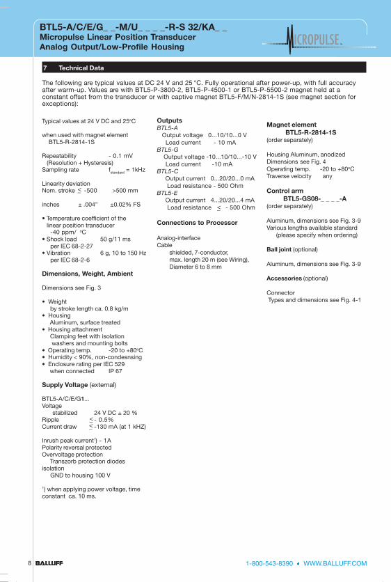
7 Technical Data
The following are typical values at DC 24 V and 25 °C. Fully operational after power-up, with full accuracyafter warm-up. Values are with BTL5-P-3800-2, BTL5-P-4500-1 or BTL5-P-5500-2 magnet held at aconstant offset from the transducer or with captive magnet BTL5-F/M/N-2814-1S (see magnet section forexceptions):
Typical values at 24 V DC and 25oC
when used with magnet element BTL5-R-2814-1S
Repeatability - 0.1 mV (Resolution + Hysteresis)Sampling rate fstandard = 1kHz
Linearity deviationNom. stroke -500 >500 mm
inches ± .004” ±0.02% FS
• Temperature coefficient of the linear position transducer
-40 ppm/ oC• Shock load 50 g/11 ms
per IEC 68-2-27• Vibration 6 g, 10 to 150 Hz
per IEC 68-2-6
Dimensions, Weight, Ambient
Dimensions see Fig. 3
• Weight by stroke length ca. 0.8 kg/m• Housing Aluminum, surface treated• Housing attachment Clamping feet with isolation washers and mounting bolts• Operating temp. -20 to +80oC• Humidity < 90%, non-condesnsing• Enclosure rating per IEC 529 when connected IP 67
Supply Voltage (external)
BTL5-A/C/E/G1...Voltage
stabilized 24 V DC ± 20 %Ripple - 0.5%Current draw -130 mA (at 1 kHZ)
Inrush peak current1) - 1APolarity reversal protectedOvervoltage protection Transzorb protection diodesisolation GND to housing 100 V
1) when applying power voltage, timeconstant ca. 10 ms.
OutputsBTL5-A Output voltage 0...10/10...0 V Load current - 10 mABTL5-G Output voltage -10...10/10...-10 V Load current -10 mABTL5-C Output current 0...20/20...0 mA Load resistance - 500 OhmBTL5-E Output current 4...20/20...4 mA
Load resistance - 500 Ohm
Connections to Processor
Analog-interfaceCable
shielded, 7-conductor,max. length 20 m (see Wiring),Diameter 6 to 8 mm
Magnet element BTL5-R-2814-1S(order separately)
Housing Aluminum, anodizedDimensions see Fig. 4Operating temp. -20 to +80oCTraverse velocity any
Control arm BTL5-GS08-_ _ _ _-A(order separately)
Aluminum, dimensions see Fig. 3-9Various lengths available standard (please specify when ordering)
Ball joint (optional)
Aluminum, dimensions see Fig. 3-9
Accessories (optional)
Connector Types and dimensions see Fig. 4-1
<_
<_<_
<_

WWW.BALLUFF.COM · 1-800-543-8390 9
BTL5-A/C/E/G_ _-M/U_ _ _ _-R-S 32/KA_ _Micropulse Linear Position Transducer
Analog Output/ Low-Profile Housing™
7 Magnet and Control Arm Diagram References
50
68
1
12
46
32
15M5x22 ISO 4762
105
9570 Nominal stroke
5
35
20
914
D
38
28
C
50
68
28
+4
Ø4.2
20
D
50
68
15
40
+10
28
55
45
C
Ø8 x 3.2 deep c-boreØ4.221
27 3
5
50
68
28
18
15.523.5
40.5 21
M5
29 3
7
50
68
28
18
15.523.5
40.5 21
M5
31
24
50
68
40
18°−18°1
4.5
70.5
40
14
.5 23
±18°
24
41
50
68
28
M5 x 10
Fig. 3-2: BTL5-P-3800-2 magnet Fig. 3-3: BTL5-P-5500-2 magnet Fig. 3-4: BTL5-P-4500-1electromagnet (24 V/100 mA)
Fig 3-1: Transducer BTL5...R Dimensions
Fig 3-5: BTL5-M-2814-15 Magnet Fig 3-7: BTL-F-2814-15 MagnetFig 3-6 BTL5-N-2814-15 Magnet
straightBKS-S 32M-00
right-angleBKS-S 33M-00Cable entry(PG 9 fitting)
Fig. 4-1: Connector (optional)
Fig. 3-8: BTL2-GS08-_ _ _ _-Aconnecting rod
Swivel eye DIN 648
Ball joint "B" DIN 71805, rotateshorizontally (part of BTL5-F-2814-1S magnet)
Jam nut DIN 934 M5
08
Fig 3-8:BTL-R-2814-15 Magnet
16
.5
40
D
50
68
36
+2
45
25
C
Ø4.2
28
15
25
7.5
M5 x 8


InductiveSensors
Connectors &Accessories
OptoelectronicSensors
MicropulseTM
Transducers
ElectromechanicalSensors
Magnetic FieldSensors
IdentificationSystems
CapacitiveSensors
GermanyGlobal HeadquartersBalluff GmbHSchurwaldstraße 973765 Neuhausen a.d.F.Telefon: +49 (0)71 58/1 73-0Telefax: +49 (0)71 58/50 10Hotline: +49 (0)71 58/1 73-370Web: www.balluff.deE-mail: [email protected]
USANorth American HeadquartersBalluff Inc.8125 Holton DriveFlorence, KY 41042Phone: (859) 727-2200Toll-free: 1-800-543-8390Fax: (859) 727-4823Web: www.balluff.comE-Mail: [email protected]
CanadaBalluff Canada, Inc.2840 Argentia Road, Unit #2Mississauga, Ontario L5N 8G4Phone: (905) 816-1494Toll-free: 1-800-927-9654Fax: (905) 816-1411Web: www.balluff.caE-mail: [email protected]
MexicoBalluff de MexicoAve. Meson del Prado #292Fracc. JuriquillaQueretaro, QRO 76230Phone: (++52-442) 234-1587Fax: (++52-442) 234-1586Web: www.balluff.com.mxE-mail: [email protected]
Complete Product Range
™
Sensors Worldwide
NO
. 000
000
• E
diti
on
0620
02 •
US
A03
90 ;
Sub
ject
to
Mo
difi
catio
n


![d btl5-aceg bz 9906 - RS Components · 2019. 10. 12. · Lage des gewinkelten BKS am BTL ... P = Position des Positionsgebers in [mm] 7.1 Maße, Gewichte, Umgebungsbedingungen Nennlänge](https://img.pdfslide.net/doc/110x75/60b4780ec5e38154102a4c9c/d-btl5-aceg-bz-9906-rs-components-2019-10-12-lage-des-gewinkelten-bks-am.jpg)