Embed Size (px)
Citation preview
153
ANALOGUE GPS REPEATER
Jarosław Magiera, Gdańsk University of Technology
Abstract
This article concerns the problem of difficulty in correct indoor Global Positioning System (GPS) signals reception due to attenuation. Radio signal repeaters are proposed as means to solve this problem.
Firstly, the GPS signal characteristics are described, emphasizing their low power in the point of reception.
In the second part, various applications of GPS signal repeater, where indoor GPS signals reception is required, are mentioned.
Afterward, types of radio signal repeaters are described.
In the fourth part, a practical realization of analogue GPS signal repeater is presented. The elements of this device are shown and described.
Next, the repeater measurement configuration and methods are described.
Following, measurements results of parameters, such as position error and carrier to noise power density ratio, are shown.
In conclusion, the possibility to use the built analogue GPS signal repeater is assessed.
1. Introduction
Global Navigation Satellite Systems (GNSS) allow users to fix the position of the receiving antenna everywhere on Earth.
Positioning is considered to be a process of calculating the position, realized by analyzing the received GNSS signals. These signals are sent form transmitters, which are placed on board satellite vehicles (SVs), going round along Earth’s orbits.
Every navigation signal contains data, necessary to calculate the SV position at the beginning of signal segment transmission. In addition, using of direct sequence spread spectrum technique makes it possible to estimate the distance between SV and receiver. Given the information about, at least, four SVs’ position and distance, one is able to estimate the receiver position in 3D.
Another advantage of using spectrum spreading is possibility to receive low power signals. Given limited power of satellite transmitters and significant propagation loss, it’s a beneficial feature. GPS signal power on receiving antenna output is about -160dBW (10-16 W), which is less than thermal noise power in equivalent bandwidth.
GPS signals power is sufficient to receive them properly through active antennas with – usually – hemispherical pattern, which are located outside, buildings with clear view of the sky.
If receiving antenna is located inside building, there’s an additional signal attenuation in walls, ceilings etc. This makes GPS signals too weak to receive them correctly.
2. GPS signals repeaters
applications
Indoor GPS receiver positioning usually isn’t possible. However, in some cases, GPS navigation signals reception in building is required.
To solve this problem, one may use a GPS signal repeater. This device receives signals through antenna placed outside building. Then, received signals are processed and fed to repeating antenna, which is located inside the room with receiver. Coordinates calculated in this receiver point the position of the receiving antenna outside the building.
An example of such situation may be an exposition of GPS receivers that takes place in a closed hall. Presented receivers are expected to have access to GPS navigation signals. That is possible, if every receiver is somehow connected to the outdoor antenna.
Using wires to establish such connection may be problematic. Firstly, due to possible large number of receivers, a complex installation would be required. Secondly, many receivers have integrated antennas, without port to connect external signal source.
Alternative way is to use a signal repeater to provide wireless indoor GPS signal source. This enables all exposed receivers to receive signals from
XII International PhD Workshop OWD 2010, 23–26 October 2010
154
common antenna, placed inside the hall. This solution is better because of shorter installation time and lower installation costs.
GPS signal repeaters may also be useful in laboratories, without direct access to satellite signals, where receivers are developed or tested.
Another situation, where repeater can be used is car fleet tracking. If a car is on a parking lot under the roof, it may still transmit (to fleet management centre) position information obtained from retransmitted GPS signals.
Other signal repeater application is uninterrupted signal access for receivers mounted in emergency vehicles. If such vehicle is in garage when emergency call is received, satellite signals cannot be tracked. Signal acquisition starts after leaving garage. Time to fix is at least 30 seconds. This wait can be skipped if there’s a repeater mounted in garage.
3. Types of signal repeaters
GPS repeater’s tasks are: navigation signal reception, regeneration and retransmission, so as to provide correct reception.
Considering method of signal processing, signal repeaters may be analogue or digital [1].
In analogue repeater received signal passes through bandpass filter in order to decrease power of noise and interference outside system frequency band. Then it is amplified and retransmitted through antenna inside building.
Block diagram of analogue repeater is shown on figure 1.
Fig. 1. Analogue signal repeater
Whereas digital signal repeater is a more complex device. Apart from amplifying the signal, it is capable of
e.g. restoring time dependencies in retransmitted signal.
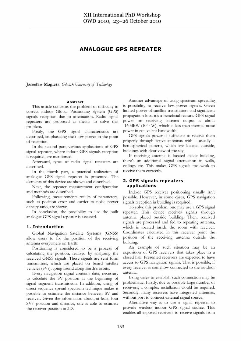
In digital generator, received signal – after passband filtering – is multiplied with local oscillator signal, in order to down convert to intermediate frequency band or baseband. Then, converted signal is baseband filtered, amplified and fed to ADC. Digital signal is then demodulated. Restored symbols are input to digital modulator. Modulated signal is converted to analog and upconverted to RF band. After passing through power amplifier it is emitted by indoor antenna.
Block diagram of analogue repeater is shown on figure 2.
An advantage of digital signal generators is that – besides amplifying the signal and restoring time dependencies – they can perform DSP algorithms. For example, channel transition characteristics compensation or error detection/correction may be done.
Fig. 2. Digital signal repeater
Realization of a digital signal repeater requires using complex digital circuits and developing dedicated software, which makes it more expensive than analogue one. What is more, in digital repeater, signal delay is more significant, due to more complex processing.
In some signal repeating cases, there is a problem of echo resulting from coupling between emitting antenna and receiving antenna. However, here this problem doesn't exist because the antennas are isolated from each other so echo cancellation isn't necessary.
4. Realization of analogue GPS
signal repeater
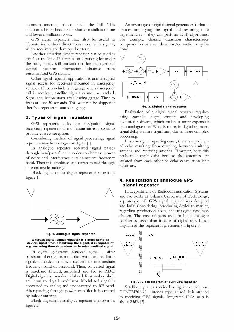
In Department of Radiocommunication Systems and Networks at Gdansk University of Technology, a prototype of GPS signal repeater was designed and built. Considering introducing device to market, regarding production costs, the analogue type was chosen. The cost of parts used to build analogue receiver is lower than in case of digital one. Block diagram of this repeater is presented on figure 3.
Fig. 3. Block diagram of built GPS repeater
Satellite signal is received using active antenna. GCNTM20A3A antenna type is used. It is attuned to receiving GPS signals. Integrated LNA gain is about 25dB [3].
155
In order to supply power to LNA, a ZFBT-4R2G+ bias-tee element is used. It is installed between receiving antenna output and amplifier input. Bias-tee has three connectors. One of them is for providing +5V DC voltage, which is passed through RF input, back to receiving antenna, so as to feed integrated LNA. On bias-tee's RF output there’s only RF signal from antenna.
Another element is a ZX60-33LN+ amplifier, which provides sufficient power of retransmitted signal. It's gain at 1500MHz is about 16dB and noise figure is about 0,95 dB[4].
Signal from the output of the amplifier is directed to the input of passive omnidirectional antenna.
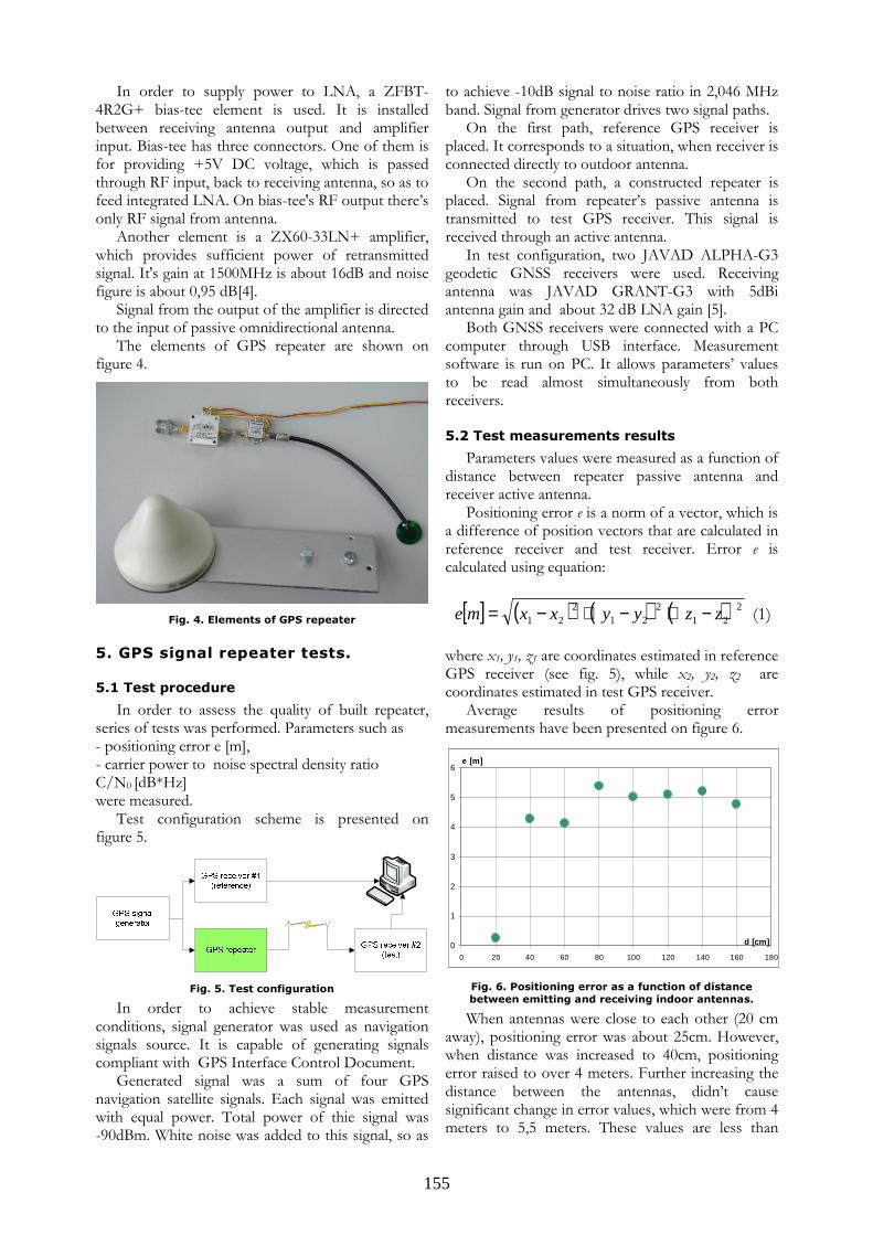
The elements of GPS repeater are shown on figure 4.
Fig. 4. Elements of GPS repeater
5. GPS signal repeater tests.
5.1 Test procedure
In order to assess the quality of built repeater, series of tests was performed. Parameters such as - positioning error e [m], - carrier power to noise spectral density ratio C/N0 [dB*Hz] were measured.
Test configuration scheme is presented on figure 5.
Fig. 5. Test configuration
In order to achieve stable measurement conditions, signal generator was used as navigation signals source. It is capable of generating signals compliant with GPS Interface Control Document.
Generated signal was a sum of four GPS navigation satellite signals. Each signal was emitted with equal power. Total power of thie signal was -90dBm. White noise was added to this signal, so as
to achieve -10dB signal to noise ratio in 2,046 MHz band. Signal from generator drives two signal paths.
On the first path, reference GPS receiver is placed. It corresponds to a situation, when receiver is connected directly to outdoor antenna.
On the second path, a constructed repeater is placed. Signal from repeater’s passive antenna is transmitted to test GPS receiver. This signal is received through an active antenna.
In test configuration, two JAVAD ALPHA-G3 geodetic GNSS receivers were used. Receiving antenna was JAVAD GRANT-G3 with 5dBi antenna gain and about 32 dB LNA gain [5].
Both GNSS receivers were connected with a PC computer through USB interface. Measurement software is run on PC. It allows parameters’ values to be read almost simultaneously from both receivers.
5.2 Test measurements results
Parameters values were measured as a function of distance between repeater passive antenna and receiver active antenna.
Positioning error e is a norm of a vector, which is a difference of position vectors that are calculated in reference receiver and test receiver. Error e is calculated using equation:
[ ] ( ) ( ) ( )221
221
221 zzyyxxme −+−+−= (1)
where x1, y1, z1 are coordinates estimated in reference GPS receiver (see fig. 5), while x2, y2, z2 are coordinates estimated in test GPS receiver.
Average results of positioning error measurements have been presented on figure 6.
0
1
2
3
4
5
6
0 20 40 60 80 100 120 140 160 180
d [cm]
e [m]
Fig. 6. Positioning error as a function of distance
between emitting and receiving indoor antennas.
When antennas were close to each other (20 cm away), positioning error was about 25cm. However, when distance was increased to 40cm, positioning error raised to over 4 meters. Further increasing the distance between the antennas, didn’t cause significant change in error values, which were from 4 meters to 5,5 meters. These values are less than
156
precision achieved in GPS’s Standard Positioning Service.
30
32
34
36
38
40
42
44
46
48
0 20 40 60 80 100 120 140 160 180
d [cm]
C/N0 [dB*Hz]
Receiver #1 (reference) Receiver #2 (test)
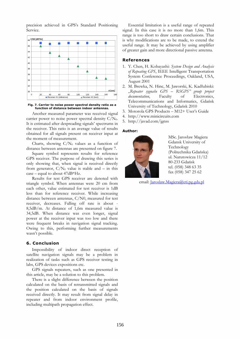
Fig. 7. Carrier to noise power spectral density ratio as a function of distance between indoor antennas.
Another measured parameter was received signal carrier power to noise power spectral density C/N0. It is estimated after despreading signals’ spectrums in the receiver. This ratio is an average value of results obtained for all signals present on receiver input at the moment of measurement.
Charts, showing C/N0 values as a function of distance between antennas are presented on figure 7.
Square symbol represents results for reference GPS receiver. The purpose of drawing this series is only showing that, when signal is received directly from generator, C/N0 value is stable and – in this case – equal to about 47dB*Hz.
Results for test GPS receiver are denoted with triangle symbol. When antennas were 20 cm from each other, value estimated for test receiver is 1dB less than for reference receiver. While increasing distance between antennas, C/N0, measured for test receiver, decreases. Falling off rate is about -8,5dB/m. At distance of 1,6m measured value is 34,5dB. When distance was even longer, signal power at the receiver input was too low and there were frequent breaks in navigation signal tracking. Owing to this, performing further measurements wasn’t possible.
6. Conclusion
Impossibility of indoor direct reception of satellite navigation signals may be a problem in realization of tasks such as GPS receiver testing in labs, GPS devices expositions etc.
GPS signals repeaters, such as one presented in this article, may be a solution to this problem.
There is a slight difference between the position calculated on the basis of retransmitted signals and the position calculated on the basis of signals received directly. It may result from signal delay in repeater and from indoor environment profile, including multipath propagation effect.
Essential limitation is a useful range of repeated signal. In this case it is no more than 1,6m. This range is too short to draw certain conclusions. That is why modifications are to be made, to extend the useful range. It may be achieved by using amplifier of greater gain and more directional passive antenna.
References
1. Y. Chen, H. Kobayashi: System Design and Analysis of Repeating GPS, IEEE Intelligent Transportation System Conference Proceedings, Oakland, USA, August 2001
2. M. Brewka, N. Hinc, M. Jaworski, K. Kadłubiski: „Repeater sygnału GPS – RSGPS” group project documentation, Faculty of Electronics, Telecommunications and Informatics, Gdańsk University of Technology, Gdańsk 2010
3. Motorola GPS Products – M12+ User’s Guide 4. http://www.minicircuits.com 5. http://javad.com/jgnss
Author:
MSc. Jarosław Magiera Gdansk University of Technology (Politechnika Gdańska) ul. Narutowicza 11/12 80-233 Gdańsk tel. (058) 348 63 35 fax (058) 347 25 62
email: [email protected]