Embed Size (px)
Citation preview
Analyses guided optimization of wide range and high efficiency turbocharger compressor
H. Sun, D. Hanna, Ford Motor Co.L. Hu, J. Zhang, Ming-Chia Lai, Wayne State Univ.
E. Krivitzky, C. Osborne, ConceptsNREC NETL Project Manager: Ralph Nine
DOE Contract: DE-FC26-07-NT43280
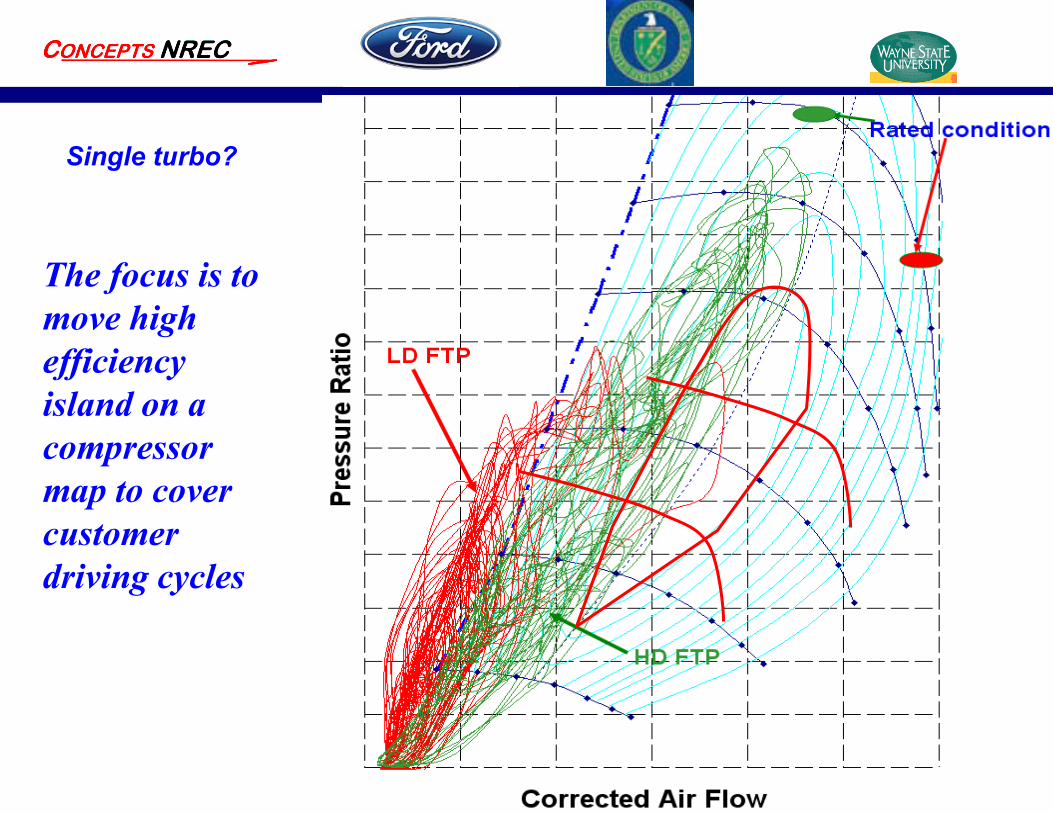
The focus is to move high efficiency island on a compressor map to cover customer driving cycles
Single turbo?
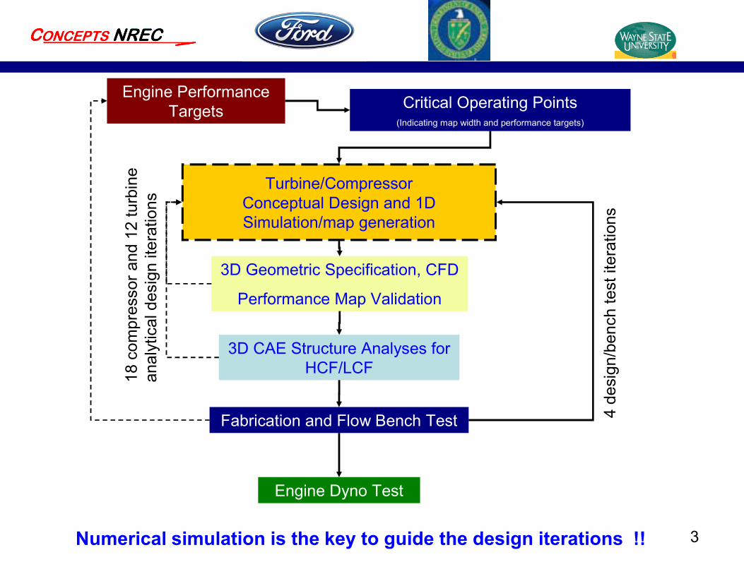
3Numerical simulation is the key to guide the design iterations !!
Engine Performance Targets Critical Operating Points
(Indicating map width and performance targets)
Turbine/Compressor Conceptual Design and 1D Simulation/map generation
3D Geometric Specification, CFD
Performance Map Validation
Fabrication and Flow Bench Test
Engine Dyno Test
3D CAE Structure Analyses for HCF/LCF18
com
pres
sor a
nd 1
2 tu
rbin
e an
alyt
ical
des
ign
itera
tions
4 de
sign
/ben
ch te
st it
erat
ions
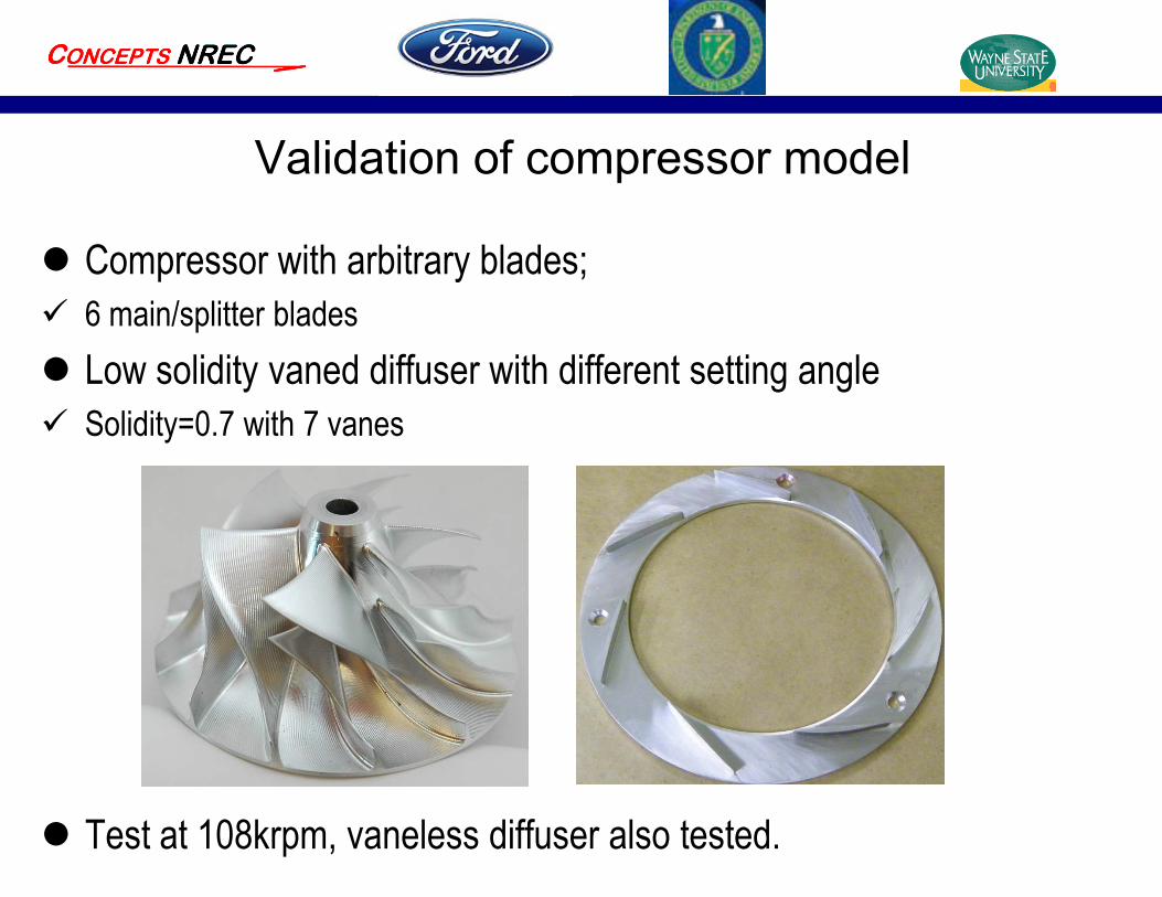
Validation of compressor model
Compressor with arbitrary blades; 6 main/splitter blades Low solidity vaned diffuser with different setting angle Solidity=0.7 with 7 vanes
Test at 108krpm, vaneless diffuser also tested.
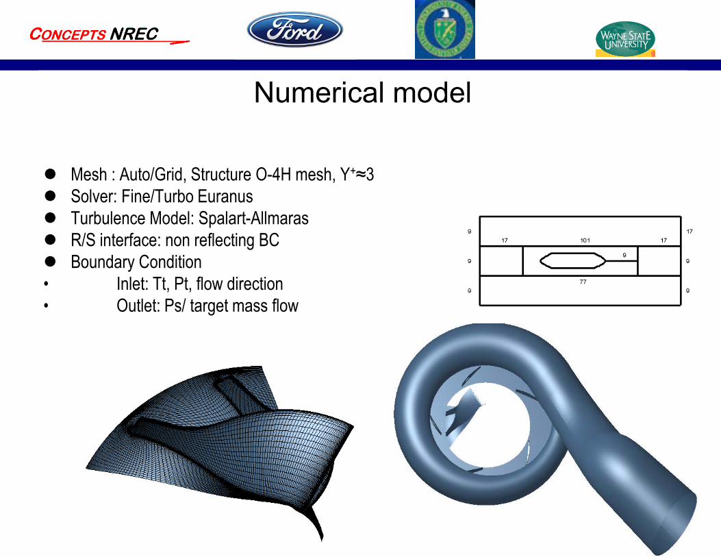
Numerical model
Mesh : Auto/Grid, Structure O-4H mesh, Y+≈3 Solver: Fine/Turbo Euranus Turbulence Model: Spalart-Allmaras R/S interface: non reflecting BC Boundary Condition• Inlet: Tt, Pt, flow direction• Outlet: Ps/ target mass flow
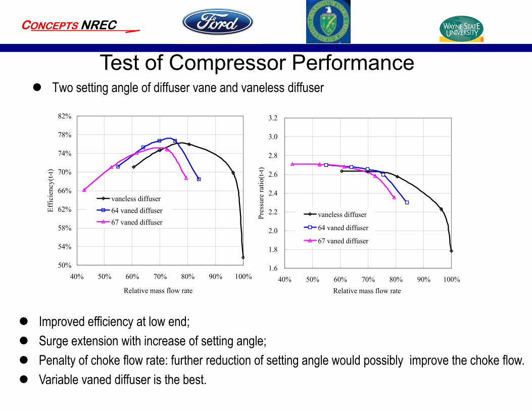
Two setting angle of diffuser vane and vaneless diffuser
50%
54%
58%
62%
66%
70%
74%
78%
82%
40% 50% 60% 70% 80% 90% 100%
Relative mass flow rate
Effic
ienc
y(t-t
)
vaneless diffuser64 vaned diffuser67 vaned diffuser
1.6
1.8
2.0
2.2
2.4
2.6
2.8
3.0
3.2
40% 50% 60% 70% 80% 90% 100%Relative mass flow rate
Pres
sure
ratio
(t-t)
vaneless diffuser
64 vaned diffuser
67 vaned diffuser
Test of Compressor Performance
Improved efficiency at low end; Surge extension with increase of setting angle; Penalty of choke flow rate: further reduction of setting angle would possibly improve the choke flow. Variable vaned diffuser is the best.
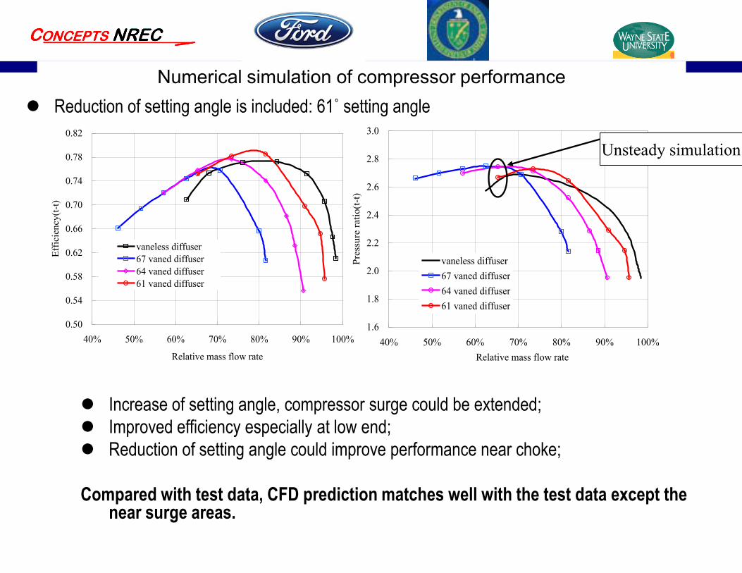
Numerical simulation of compressor performance Reduction of setting angle is included: 61˚ setting angle
0.50
0.54
0.58
0.62
0.66
0.70
0.74
0.78
0.82
40% 50% 60% 70% 80% 90% 100%
Relative mass flow rate
Effic
ienc
y(t-t
)
vaneless diffuser67 vaned diffuser64 vaned diffuser61 vaned diffuser
1.6
1.8
2.0
2.2
2.4
2.6
2.8
3.0
40% 50% 60% 70% 80% 90% 100%Relative mass flow rate
Pres
sure
ratio
(t-t)
vaneless diffuser67 vaned diffuser64 vaned diffuser61 vaned diffuser
Increase of setting angle, compressor surge could be extended; Improved efficiency especially at low end; Reduction of setting angle could improve performance near choke;
Compared with test data, CFD prediction matches well with the test data except the near surge areas.
Unsteady simulation
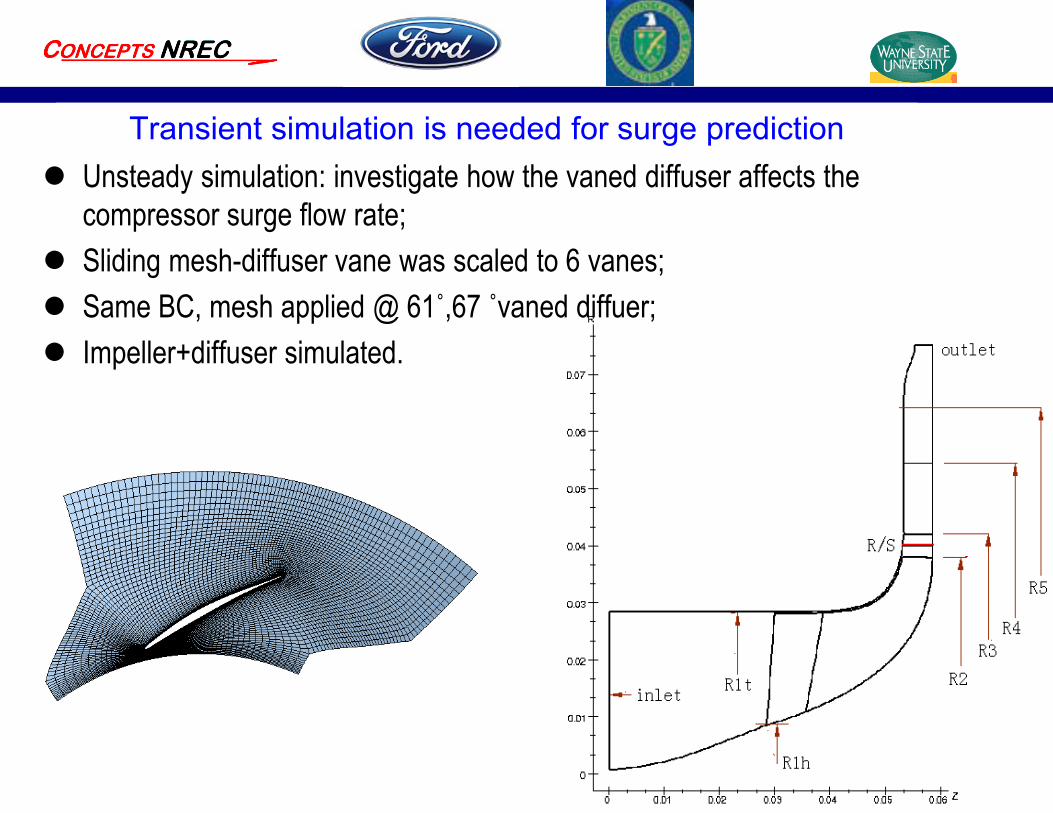
Transient simulation is needed for surge prediction Unsteady simulation: investigate how the vaned diffuser affects the
compressor surge flow rate; Sliding mesh-diffuser vane was scaled to 6 vanes; Same BC, mesh applied @ 61˚,67 ˚vaned diffuer; Impeller+diffuser simulated.
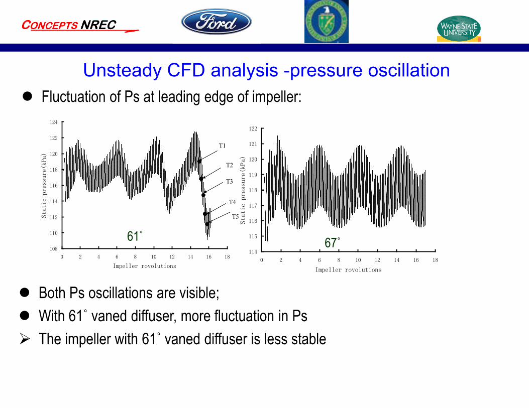
Unsteady CFD analysis -pressure oscillation Fluctuation of Ps at leading edge of impeller:
108
110
112
114
116
118
120
122
124
0 2 4 6 8 10 12 14 16 18
Impeller rovolutions
Static pressure(kPa)
T2
T1
T3
T4
T5
114
115
116
117
118
119
120
121
122
0 2 4 6 8 10 12 14 16 18
Impeller rovolutions
Static pressure(kPa)
61˚ 67˚
Both Ps oscillations are visible; With 61˚ vaned diffuser, more fluctuation in Ps The impeller with 61˚ vaned diffuser is less stable
0 10000 20000 30000 400000
500
1000
1500
2000
Magnitude
Frequency
0 10000 20000 30000 400000
500
1000
1500
2000
2500
Frequency
Magnitude
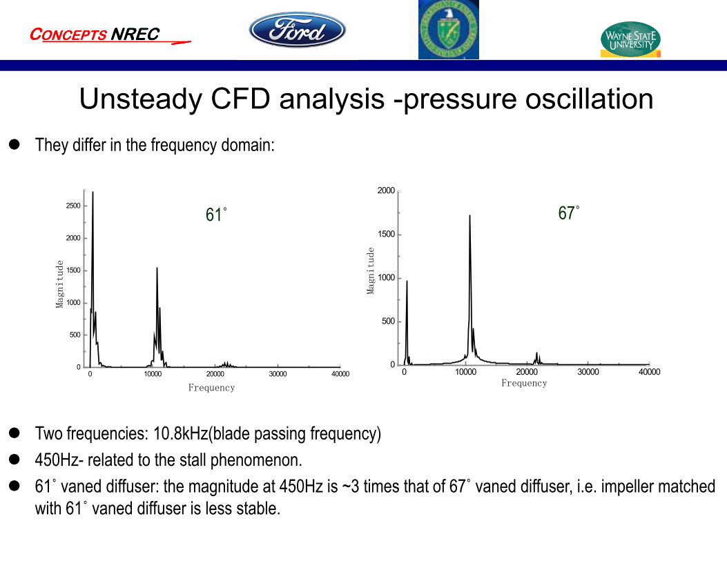
They differ in the frequency domain:
61˚ 67˚
Two frequencies: 10.8kHz(blade passing frequency) 450Hz- related to the stall phenomenon. 61˚ vaned diffuser: the magnitude at 450Hz is ~3 times that of 67˚ vaned diffuser, i.e. impeller matched
with 61˚ vaned diffuser is less stable.
Unsteady CFD analysis -pressure oscillation
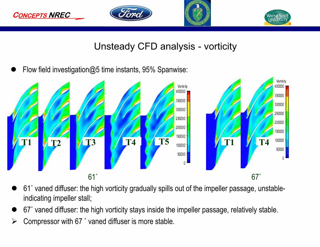
Unsteady CFD analysis - vorticity
Flow field investigation@5 time instants, 95% Spanwise:
61˚ 67˚ 61˚ vaned diffuser: the high vorticity gradually spills out of the impeller passage, unstable-
indicating impeller stall; 67˚ vaned diffuser: the high vorticity stays inside the impeller passage, relatively stable. Compressor with 67 ˚ vaned diffuser is more stable.
T1 T1T2T1 T4T3 T5 T4T1

Unsteady CFD analysis - entropy
Flow field investigation@5 time instants, 95% Spanwise:
61˚
Entropy distribution: 61˚ vaned diffuser: high entropy area gradually spills out of the impeller passage, entropy increased
– impeller unstable; 67 ˚ vaned diffuser: more stable – increased diffuser vane angle is able to stabilize impeller flow.
T1 T2 T3 T4 T5 T1 T4
67˚
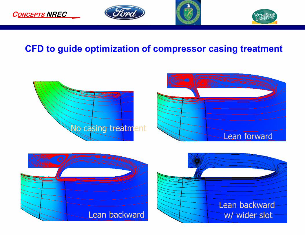
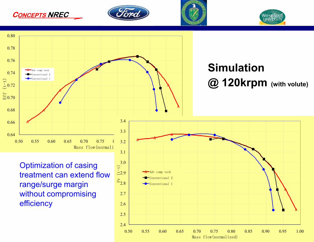
CFD to guide optimization of compressor casing treatment
Lean backward
Lean forwardNo casing treatment
Lean backward w/ wider slot
0.64
0.66
0.68
0.70
0.72
0.74
0.76
0.78
0.80
0.50 0.55 0.60 0.65 0.70 0.75 0.80 0.85 0.90 0.95 1.00Mass flow(normalized)
Eff (t-t)
Adv comp tech
Conventional 2
Conventional 1
Simulation@ 120krpm (with volute)
2.4
2.5
2.6
2.7
2.8
2.9
3.0
3.1
3.2
3.3
3.4
0.50 0.55 0.60 0.65 0.70 0.75 0.80 0.85 0.90 0.95 1.00Mass flow(normalized)
Pr (t-t)
Adv comp tech
Conventional 2
Conventional 1
Optimization of casing treatment can extend flow range/surge margin without compromising efficiency
Conclusions
CFD simulation tool (Numeca) has been demonstrated to be very effective to guide the compressor optimization (the compressor went through 18 design iterations and only 4 designs went to hardware build/test);
The accuracy of CFD tool has been validated in steady state and transient simulations for both vaned and vaneless compressors;
Variable geometry compressor can extend the flow range dramatically but may have reduced peak efficiencies;
Optimization of compressor casing treatment shows the potential of improvement in both surge margin and flow capacity without compromising of efficiency.


![MAYEKAWA Global (MYCOM) - SCV SERIES...Screw Compressor [Single Stage] Open Type 2950rpm SCV SERIES Variable Vi Mechanism (2.63-5.80 range) to Efficiently Cover Wide Temperature Range](https://img.pdfslide.net/doc/110x75/6098811fbd105955e4194530/mayekawa-global-mycom-scv-series-screw-compressor-single-stage-open-type.jpg)