Embed Size (px)
DESCRIPTION
english
Citation preview

Analysis & Design of a Simplified Patient Care Clinic System INFO 620: Information Systems Analysis and Design Spring 2011
Daniel Dzubow, Domenic Rocco, Sarah Slough 6/8/2011

1
Contents INTRODUCTION .............................................................................................................................................................................. 2
CHAPTER I: SYSTEM ANALYSIS ........................................................................................................................... 4 1. THE PROBLEM STATEMENT ................................................................................................................................................... 4 2. REQUIREMENTS ........................................................................................................................................................................ 5 2.1 Functional Requirements ............................................................................................................................................. 5 2.2 Data Requirements ......................................................................................................................................................... 6 2.3 Business Rules and Logic .............................................................................................................................................. 7 2.4 Non-‐Functional Requirements ................................................................................................................................... 8 2.5 Other Important Assumptions ................................................................................................................................... 8
3. USE CASE MODEL .................................................................................................................................................................... 9 3.1 Actors and their Goals ................................................................................................................................................... 9 3.2 Use Case Diagram ......................................................................................................................................................... 10 3.3 Overview Section of the Use Cases ......................................................................................................................... 11 3.4 Use Case Descriptions for Primary Use Cases ................................................................................................... 17 3.5 Discussion ......................................................................................................................................................................... 27
4. CLASS MODEL ....................................................................................................................................................................... 29 4.1 TCM Table ........................................................................................................................................................................ 29 4.2 Analysis Class Diagram .............................................................................................................................................. 31 4.4 Selected Association Definitions ............................................................................................................................. 32 4.5 Discussion ......................................................................................................................................................................... 33
CHAPTER 2: SYSTEM DESIGN ........................................................................................................................... 35 5. SEQUENCE DIAGRAMS .......................................................................................................................................................... 35 5.1 System Sequence Diagrams ...................................................................................................................................... 35 5.2 Sequence Diagrams and Individual Validation and Discussion ............................................................... 38 5.3 Validation and Discussion ......................................................................................................................................... 45
6. DESIGN CLASS DIAGRAM ...................................................................................................................................................... 46 6.1 Design Class Diagram ................................................................................................................................................. 46 6.2 Validation and Discussion ......................................................................................................................................... 47
CHAPTER 3: PHYSICAL DESIGN ....................................................................................................................... 48 7. RELATIONAL DATABASE SCHEMA ...................................................................................................................................... 48 7.1 Relational Database Schema ................................................................................................................................... 48 7.2 Discussion ......................................................................................................................................................................... 50
CHAPTER 4: EVALUATION OF ANALYSIS & DESIGN .................................................................................. 51 8. EVALUATION OF ANALYSIS & DESIGN ................................................................................................................................ 51 8.1 Evaluation of Project ................................................................................................................................................... 51 8.2 Evaluation of UML and Tool .................................................................................................................................... 51
REFERENCES .......................................................................................................................................................... 53 APPENDIX ............................................................................................................................................................... 54 9. APPENDIX ............................................................................................................................................................................... 54 9.1 Lessons Learned ............................................................................................................................................................ 54 9.2 Division of the work among members ................................................................................................................. 56 9.3 Unsolved problems ....................................................................................................................................................... 58
CERTIFICATION .................................................................................................................................................... 58

2
Introduction Medical information systems are notorious for being outdated, needlessly complex, redundant, disjointed and increasingly expensive. Smaller clinics with simpler needs of managing appointments, basic medical histories, payments, prescriptions and referrals cannot afford more complex systems and do not need them. We chose to analyze the needs for such a clinic and design a system that sufficiently meets the needs of the clinic without involving excessive features while maintaining a simple organizational design. Our overall plan and methodology throughout the analysis and design of the patient care clinic system was to create a system that would allow for information to be accessed, viewed and organized in different ways as outlined in our requirements. In order to do this, we consistently reevaluated those requirements, as well as our use case diagram and descriptions and our other diagrams. From our own experience using clinics and also studying healthcare systems, we observed that one of the largest problems is redundancy of information and disjointedness of patient files. As a primary goal, we sought to create unified patient information. We wanted to create a system that connected all of a patient’s information and data, so while it is easily accessible, it will reduce redundancy of information. In order to create this simple and unified system, we consistently reevaluated our progress to ensure that staff members (whether basic or medical staff), would have immediately accessible use case processes that were not overlapping, but offered enough complexity that they could search patient data from a variety of angles. For example, doctor may be able to search a patient medical history by visit or search unpaid invoices by visit, both of which would connect back to the patient and the patient’s visit. In each of our diagrams, the structure and methodology consistently reflect our requirements, which also changed as our understanding of the system evolved. While the creation of a system often involves multiple team members who complete individual tasks to contribute to the whole, it is also important that the team continuously discuss the requirements and understanding of the system, so that the individual parts interact with the whole system in the same way. In the following pages of this analysis and design, individual team members took on different tasks and also completed individual assignments, but in order for each individual section, as well as the whole, to sufficiently and completely meet the requirements and interact appropriately with various actors and with the rest of the system, it was necessary for team members to, at minimum, discuss each section as a group, offering suggestions and comparing methodology ideas. This system analysis and design will ultimately demonstrate a unified understanding of the patient clinic care system’s needs as well as a simple, but complete approach to unifying patient data for the clinic’s requirements. The use case diagram shows the primary actors in the clinic and the use cases that are expanded upon in use
3
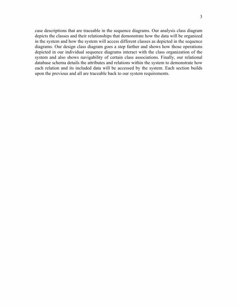
case descriptions that are traceable in the sequence diagrams. Our analysis class diagram depicts the classes and their relationships that demonstrate how the data will be organized in the system and how the system will access different classes as depicted in the sequence diagrams. Our design class diagram goes a step farther and shows how those operations depicted in our individual sequence diagrams interact with the class organization of the system and also shows navigability of certain class associations. Finally, our relational database schema details the attributes and relations within the system to demonstrate how each relation and its included data will be accessed by the system. Each section builds upon the previous and all are traceable back to our system requirements.

4
CHAPTER I: System Analysis
1. The Problem Statement
A small local clinic wants to digitally organize its patients' medical records and patient payment system. a. Context and Importance of the System
In a medical patient care setting, confidentiality and organization of patient medical records, insurance and financial information is of utmost importance. A small clinic cannot afford, nor do they require the large-scale, expensive and complicated systems used by hospitals and larger organizations. Instead, they need a medical software system that can handle their more basic needs while staying within a manageable budget. The system must handle appointment scheduling, organization of patient records, payment processing and tracking and management of medical history including appointment notes, creating diagnosis and writing prescriptions and referrals. It must also be secure and clearly viewable in many formats. Accurate tracking of patient records is crucial for effective patient care as well as for the financial viability of the clinic. b. Overall Goals of the System
The main functions of the system are to manage employee information, schedule patient appointments, maintain patient medical records and process and track patient payments. c. Scope of the Project
IN-Scope: The PCCS will include basic employee information, appointment information, patient medical records, medical history, prescriptions, diagnosis descriptions, referrals, patient payment history and invoices and reports. OUT-Scope: The PCCS will not include medical diagnosis or prescription databases to process prescriptions. Credit processing and insurance processing will be excluded, but will be recorded as payment in the system. The system will not include office activities such as payroll, staff scheduling or supply purchase orders.

5
2. Requirements
2.1 Functional Requirements The PCCS will need to allow the following functions:
1. Log in 2. Log out 3. Manage Patients
a. Add a new patient b. Edit patient information c. Archive new and updated patient forms, including HIPAA with medical
records. d. Patient Lookup
4. Find a patient and applicable information 5. View patient list, sortable by doctor and visit and appointment dates/times 6. View patient information, sortable by field 7. Manage employee users
a. Add employee b. Edit employee information c. Delete employee d. Add user login and password e. Edit employee privileges
8. Manage appointments a. Add appointments b. Edit appointment information c. Delete appointments
9. View appointments and patient visits, sortable by date or by patient 10. Add patient medical history exam date 11. Edit patient medical history
a. Add initial medical history b. Edit initial medical history c. Add appointment notes d. Edit appointment notes e. Add prescription, diagnosis or referral to visit f. Edit prescription, diagnosis or referral g. Upload patient forms h. Edit patient forms
12. View medical history by visit date 13. Search and view medical history by field (allergy, medical condition, medication,
prescriptions, diagnoses, referral, forms or appointment notes) 14. Make patient payment
a. Make payment with credit card b. Make payment with cash or check c. Submit patient insurance claim
15. View payments, sortable by patient, date, and visit

6
16. Mail invoices by printing invoices and using patient addresses to print mailing labels.
17. Generate invoices for a specific patient, all patients, or patients with outstanding balance
18. Generate Reports a. Payment history for patient b. Patients with an outstanding balance c. Patient payments with insurance claims that need to be filed d. Patient payments with insurance issues e. Monthly report
i. Total billing per month ii. Total billing per month per doctor
iii. Total payments per month iv. Total patient payments per month
f. Yearly report i. Total billing per year
ii. Total billing per year per doctor iii. Total payments per year iv. Total patient payments per year
2.2 Data Requirements
1. For patient personal information, the system will keep track of patient ID, patient last name, patient first name, birth date, address, social security number, status of current patient forms and preferred doctor. Patient phone numbers and types of phone numbers will be stored. The system will store patient emergency contact information including first name, last name, phone number, relationship to patient and the date the contact was added.
2. The system will also track initial medical history including a history ID, tobacco use, alcohol use, medications used (including over-the-counter medications), allergies and previous conditions. In order to be registered in the system, at least one phone number, at least one emergency contact, but may have zero appointments or visits.
3. Patient insurance information will include policy number, group number subscriber name and subscriber address. It will also indicate whether the patient insurance is active or not if a patient may have previous or alternative insurance policies. The insurance carrier information including carrier id, name, address, phone number and fax number will also be stored. A patient may not have insurance.
4. During the initial visit the initial medical history will be recorded including alcohol use, tobacco use, preferred doctor, descriptions of patient allergies, current patient conditions and names of current patient medications, including over the counter drugs and vitamins, will be stored along with the date they were added or updated. These fields will be confirmed and updated during subsequent appointments.

7
5. Medical history will be tracked by visit date in which the date, patient height, patient weight, blood pressure, heart rate and temperature will be recorded along with the confirmation of general medical history information including alcohol and tobacco use, allergies, medications and conditions.
6. Diagnoses, prescriptions and referrals will also be recorded by patient visit. Patient referrals by doctor will include a generated referral id, referred doctor name, referred facility, referral description and date referred. Patient prescriptions will be stored including a generated prescription id, prescription name, instructions and prescription date. Diagnoses made during visits will also be recorded with the diagnosis code, description and the date of diagnosis. Diagnosis, referral and prescription will only be associated with one doctor.
7. For employee information, the system will track employee ID, employee login, employee password, employee name, date of birth, social security number, address, primary phone number and start date.
8. For appointments, the system will track appointment ID, date, time and reason for appointment. Each appointment will be scheduled by one staff member and each visit will be supervised by one doctor and at least one nurse. An appointment or visit will only be associated with one patient. Each appointment will be associated with one visit. Each visit may or may not have an appointment. For each visit the system will track visit ID, date and time.
9. For each invoice, the system will track the invoice number, the invoice total, the invoice status and the date. Invoices will contain invoice items that will have a sequence number, a description and a price. Each patient appointment will have at least one invoice.
10. For each payment, the system will track the payment ID, the payment amount and the date. Each payment will be associated with at least on invoice. Payment method will be recorded. Credit payments will have a credit card number. Check payments will have a check number. Insurance payments will have a claim number.
2.3 Business Rules and Logic
1. Employee information and privileges will be managed by an administrator, the doctor at the clinic with highest seniority and a leadership role.
2. Basic patient information, excluding medical history, will be managed by all staff members.
3. Patient appointments will be managed by an office staff member. 4. Doctors and nurses will have access to view patient information, but will not be
able to manage users or privileges. 5. Medical staff, nurses and doctors, will be able to search medical histories, manage
appointment notes (including managing the medical history) and add an initial medical history.
6. Doctors will be able to create diagnoses and manage prescriptions and referrals. 7. Payments are applied to one invoice at a time beginning with the oldest invoice. 8. The outstanding balance of a patient will always reflect the sum of balances of all
the unpaid billable items.

8
9. All staff members are able to process payments, but this will mostly be handled by administrative staff.
10. All staff members will be able manage appointment scheduling, but doctors and nurses will be responsible for appointment exam notes.
11. Medical procedure costs are determined by outside governing medical agencies. 12. Patients will only receive invoices if they have outstanding balances. 13. Either cash, credit or check information must be entered at the time of a patient
payment. 14. An insurance co-payment will be deducted from the total billed amount. 15. Outstanding balances must reflect total owed until insurance claim is processed,
but payment may be placed on hold until claim is processed. 16. The status of billable items will either be “Un-invoiced”, “Paid-in-full”, “Paid-in-
partial” or “Insurance claim processing”. These status updates will be automatic. 17. The system must record who added, edited or updated anything in the system. 18. The system will protect patient privacy and confidentiality by preventing copying
of files, limiting need-based employee privileges and requiring frequent password changes.
19. Copies of signed patient forms, especially HIPAA, must be kept with each patient’s medical history and filed by an administrative staff member, nurse or doctor upon initial visit.
2.4 Non-‐Functional Requirements
1. The system will be a web-based intranet application (compatible with major web browsers).
2. The system is to feature a help page with user tips and procedural guidelines. 3. User authentication will be required to gain access to the system. 4. Development startup budget is not to exceed $10,000. 5. The initial analysis and design timeline before prototyping or development is
eight weeks. 6. The system will have a graphical user interface.
2.5 Other Important Assumptions
1. The system is to be built on ASP.Net 2.0+ using Microsoft Visual Studio. 2. The system's database is to be built on MSSQL. 3. Credit card processing, insurance processing and medical databases are external
to the system. 4. Employees will scan in any medical forms to include with the medical history.

9
3. Use Case Model
3.1 Actors and their Goals Staff: All staff of the clinic share goals of logging in and out of the system, managing patient, generating financial reports, managing appointments, processing payments and generating invoices. Staff includes Medical Staff as well as Administrative Staff. Medical Staff: Medical Staff are a subclass of Staff. Medical Staff members have goals of searching medical history, managing appointment notes (which comprise the medical history), adding the initial medical history for patients and managing exam notes. Medical Staff include nurses and doctors. Doctor: Doctors of the clinic are a specialization of the Staff actor. They have the unique goals of creating diagnoses, creating referrals and managing prescriptions. Administrator: The Administrator is a specialization of the Doctor actor. The Administrator has an additional goal of managing users. Credit Card Company: The credit card company is a supporting actor, an external system that has a goal of processing the clinic’s credit card payments. Insurance Company: The insurance company is a supporting actor, an external system that has a goal of processing an insurance claim submitted by the clinic.

10
3.2 Use Case Diagram
<<extend>>
Manage UsersAdministrator
Mail Invoices
<<extend>>
Create Diagnosis
Create Referral
Manage Prescriptions
Doctor
Credit Card Company
Validate Credit Card Payment
Insurance Company
Log In
Generate Reports
Manage Patient
Manage Appointments
Process Payments
Submit Insurance Claim
Generate Invoices
Staff
Add Initial Medical History
Manage Medical History
Search Medical History
Manage Exam Notes
Medical Staff

11
3.3 Overview Section of the Use Cases Use Case 1: Log In
Actor(s): All Staff Members
Purpose: To authenticate users of the system and ensure confidentiality of the clinic’s system.
Overview: “Log In” details the process of logging in and authenticating username, password and tracking of actions within the clinic system
Use Case 2: Generate Reports
Actor(s): All Staff Members
Purpose: To track financial status of the clinic and track various forms of payment in process
Overview: “Generate Reports” details the process of selecting various dates and types of financial information from payment and patient information, compiling them according to selected fields and printing, displaying or emailing them as requested.
Use Case 3: Manage Patient
Actor(s): All Staff Members
Purpose: To add, edit or look up basic patient information in the system records for purposes of contacting the patient for appointments or payment concerns and verifying identity or to access their patient file.
Overview: “Manage Patient” shows the process of adding, editing and looking up patient information and confirming that all necessary information and forms are included within the patient information.

12
Use Case 4: Manage Appointments
Actor(s): All Staff Members
Purpose: To create, edit, confirm and print daily patient appointments
Overview: “Manage Appointments” details the process of the creation of new appointments, cancelling or editing appointments and printing the daily appointment schedules for doctors and nurses.
Use Case 5: Process Payments
Actor(s): All Staff Members
Purpose: To record the patient payments
Overview: “Process Payments” details the process of an employee accepting payment from a patient for a patient visit. Types of payment accepted include cash, check, and credit card.
Use Case 6: Validate Credit Card Payment
Actor(s): All Staff Members/Credit Card Company
Purpose: To validate payments made on patient credit cards.
Overview: Balances paid on credit cards initiate this use case. Credit card information is recorded and authenticated through the external credit card payment system. A valid transaction results in payment towards the outstanding balance of an invoice.

13
Use Case 7: Submit Insurance Claim
Actor(s): All Staff Members/Insurance Company
Purpose: To submit an insurance claim for patient visit services rendered on behalf of the patient.
Overview: The “Submit Insurance Claim” process details the steps of compiling the patient visit information, cost for services rendered and all applicable information and sending it to the patient’s insurance carrier. The insurance company will approve or deny the claim.
Use Case 8: Generate Invoices
Actor(s): All Staff Members
Purpose: To compile patient payments, payment histories and insurance claims to generate invoices to be kept on record and sent to patients with outstanding balances.
Overview: The “Generate Invoices” process will detail the search process for patients, outstanding balances or other search constraints, the compilation of this information in invoice form and the display, printing or emailing of the invoices to appropriate patient or staff member.
Use Case 9: Mail Invoices
Actor(s): All Staff Members
Purpose: To automatically email or prepare invoices and mailing labels to be sent to patients
Overview: The “Mail Invoices” process is included in generating invoices as invoices will be automatically printed with mailing labels the patient has an outstanding balance.

14
Use Case 10: Manage Medical History
Actor(s): Medical Staff
Purpose: To edit or add visits and other related information to a patient’s medical history
Overview: The “Manage Medical History” use case entails the process of accessing a patient’s record, validating patient information and confirming medical history information including allergies, medications and conditions.
Use Case 11: Search Medical History
Actor(s): Medical Staff
Purpose: To search a patient’s medical history utilizing various fields.
Overview: The “Search Medical History” use case entails the process of searching a patient’s medical history by entering various fields including condition, medication, allergy, appointments, diagnoses, prescriptions or referrals.
Use Case 12: Add Initial Medical History
Actor(s): Medical Staff
Purpose: To record a patient’s existing conditions upon first visit
Overview: The “Add Initial Medical History” use case is performed once by Medical Staff during the first visit. It entails adding existing conditions, medications (including over-the-counter medications) and allergies as well as alcohol and tobacco use. This information may be updated by the “Manage Medical History” use case, but will only be added once.

15
Use Case 13: Manage Exam Notes
Actor(s): Medical Staff
Purpose: To add or edit exam notes for a patient’s appointment
Overview: The “Manage Exam Notes” use case details the process of adding the basic nurse exam information to the appointment record for a patient.
Use Case 14: Create Diagnosis
Actor(s): Doctors
Purpose: If required, to add a diagnosis to a patient medical history along with the doctor’s notes and suggested treatment
Overview: “Create Diagnosis” details the process of adding a diagnosis and a diagnosis code, if required, to a patient’s medical history associated with an appointment. It is an extending use case unique to doctors of the “Manage Medical History” use case.
Use Case 15: Create Referral
Actor(s): Doctors
Purpose: To refer a patient to another doctor or specialist for further medical needs
Overview: “Create Referral” shows the process of inputting appropriate specialists, clinics or organizations for further follow-up then displaying, printing or emailing the appropriate information. It is an extending use case unique to doctors of the “Manage Medical History” use case.

16
Use Case 16: Manage Prescriptions
Actor(s): Doctors
Purpose: To add or edit a patient’s prescriptions
Overview: Details the process of validating doctor and patient information, selecting a drug and dosage and adding it to the medical history. It is an extending use case unique to doctors of the “Manage Medical History” use case.
Use Case 17: Manage Users
Actor(s): Chief of Staff
Purpose: The head of the clinic will be able to manage user (employee) accounts and privileges to ensure the security of the clinic’s system
Overview: “Manage Users” will detail the process of adding and editing employee/user information as well as their usernames, passwords and security clearances. It will also detail the tracking/reporting of user actions, so any editing or recording of medical histories will be recorded.

17
3.4 Use Case Descriptions for Primary Use Cases
Use Case 003: Manage Patient – Dan Dzubow USE CASE # 003 USE CASE Name Manage Patient ACTOR All Staff Members Goal (1 phrase) To add or edit basic patient information in the system records for
purposes of contacting the patient for appointments or payment concerns and verifying identity.
Overview and scope “Manage Patient” shows the process of adding and editing a patient and their personal information.
Level Primary Preconditions - Staff member is logged into the system.
- Patient paperwork is completed.
Postconditions in words (write in passive and past tense)
- If patient was not currently in system, patient was assigned a unique, identifiable ID number (Patient ID)
- Patient personal information was stored (ssn, first name, last name, dob, address and preferred doctor).
- Date that the information was added/last updated was recorded.
- Patient form_status was modified. - PatientEmergencyContact was created/updated. - PatientPhoneNumber was created/updated. - PatientInsurance was created/updated. - Patient and PatientEmergencyContact was connected. - Patient and PatientPhoneNumber was connected. - Patient and PatientInsurance was connected. - InsuranceCarrier and PatientInsurance was connected.
Trigger - A patient has filled out the necessary paperwork to be
input into the system. Included Use Cases Log in Extending Use Cases None MAIN SUCCESSFUL SCENARIO in numbered sequence Reference “included use cases” in this section using
Actor Action System Action 1. Actor logs in 2. INCLUDE Log in 3. System displays GUI for main
System Interface. 4. Actor selects ‘Patients’ tab.
5. System displays main Patient Interface.
6. Actor selects ‘Add Patient’ button.
7. System populates a blank patient form.

18
INCLUDE ius_name 8. Actor enters patient information into corresponding fields.
9. Actor selects to ‘Submit’ the patient form.
10. System generates unique patientID to assign to new patient.
11. System saves patient form into database.
12. System returns to main patient interface.
OTHER SUCCESSFUL SCENARIOS (Specify any successful variations of the normal execution path, including any extension points using EXTEND eus_name)
Step Branching Action 6a. Actor enters patient name or patientID into search field.
1. System displays search results.
2. Actor choses patient. 2. System opens most current patient form for editing.
3. Continue from step 8 of Main Success Scenario.
UNSUCCESSFUL SCENARIOS (erroneous situations)
Conditions Actions *a Actor tries to submit patient form without filling in required field(s).
1. A message is displayed prompting the Actor to enter required information.
*b Actor chooses to exit form without submitting.
1. A message pops up warning the Actor that all unsaved data will be lost and asks to confirm cancellation or return to patient form. Actor will be sent to main Patient Interface upon cancellation.
Priority in scheduling Primary Frequency Approximately 10-20 times daily. Business rules and data logic
• The system must record who added, edited or updated anything in the system.
• Updated patient information forms will not overwrite existing form. They will save as a new file, uniquely identified by a timestamp of the date and time that is was submitted.
• The system will protect patient privacy and confidentiality by preventing copying of files.
• Original hardcopies of signed patient documents, especially HIPAA, must be kept with each patient’s medical history and filed by an administrative staff member, nurse or doctor upon initial visit.
19
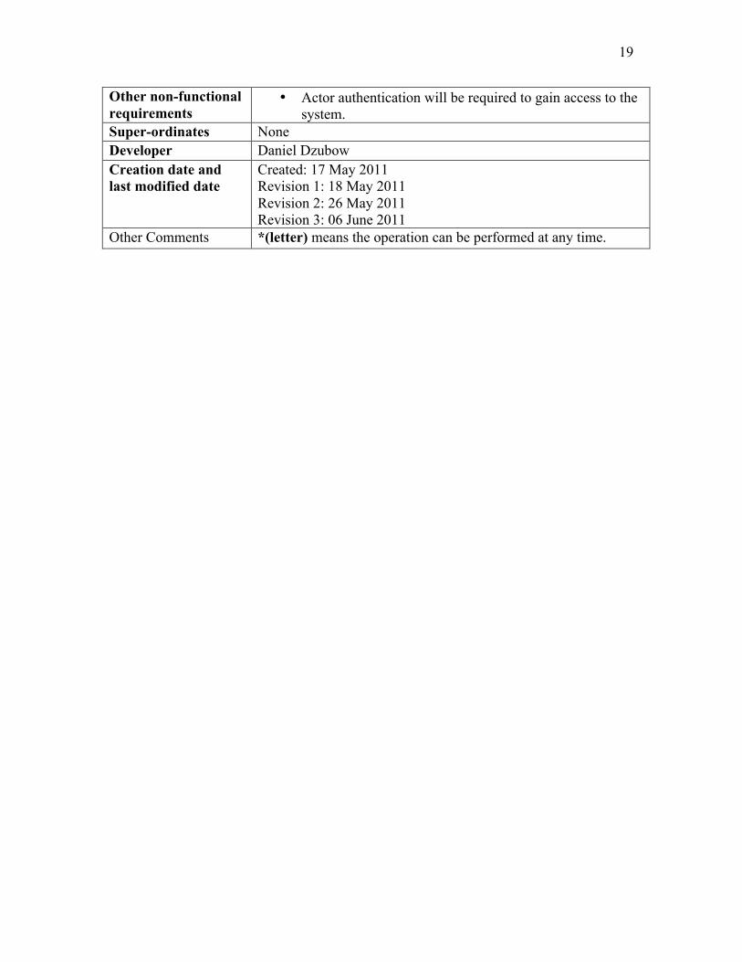
Other non-functional requirements
• Actor authentication will be required to gain access to the system.
Super-ordinates None Developer Daniel Dzubow Creation date and last modified date
Created: 17 May 2011 Revision 1: 18 May 2011 Revision 2: 26 May 2011 Revision 3: 06 June 2011
Other Comments *(letter) means the operation can be performed at any time.
20
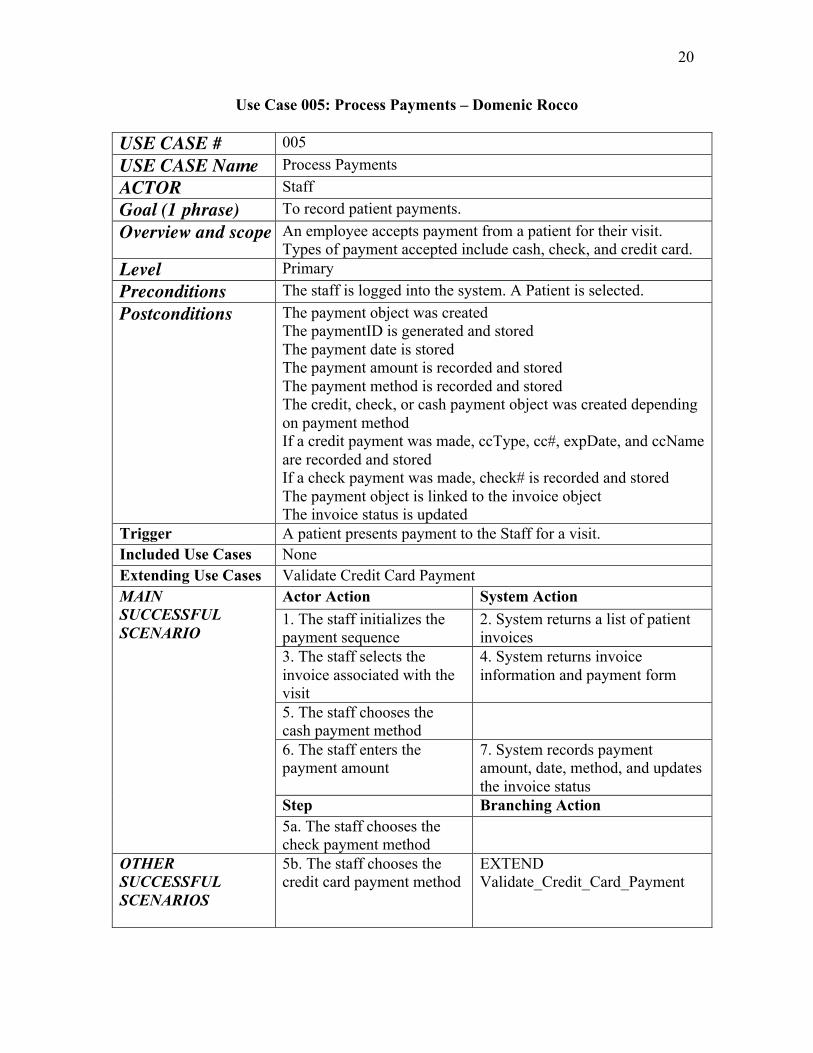
Use Case 005: Process Payments – Domenic Rocco USE CASE # 005 USE CASE Name Process Payments ACTOR Staff Goal (1 phrase) To record patient payments. Overview and scope An employee accepts payment from a patient for their visit.
Types of payment accepted include cash, check, and credit card. Level Primary Preconditions The staff is logged into the system. A Patient is selected. Postconditions The payment object was created
The paymentID is generated and stored The payment date is stored The payment amount is recorded and stored The payment method is recorded and stored The credit, check, or cash payment object was created depending on payment method If a credit payment was made, ccType, cc#, expDate, and ccName are recorded and stored If a check payment was made, check# is recorded and stored The payment object is linked to the invoice object The invoice status is updated
Trigger A patient presents payment to the Staff for a visit. Included Use Cases None Extending Use Cases Validate Credit Card Payment MAIN SUCCESSFUL SCENARIO
Actor Action System Action 1. The staff initializes the payment sequence
2. System returns a list of patient invoices
3. The staff selects the invoice associated with the visit
4. System returns invoice information and payment form
5. The staff chooses the cash payment method
6. The staff enters the payment amount
7. System records payment amount, date, method, and updates the invoice status
Step Branching Action 5a. The staff chooses the check payment method
OTHER SUCCESSFUL SCENARIOS
5b. The staff chooses the credit card payment method
EXTEND Validate_Credit_Card_Payment
21
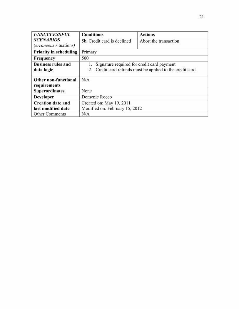
UNSUCCESSFUL SCENARIOS (erroneous situations)
Conditions Actions 5b. Credit card is declined
Abort the transaction
Priority in scheduling Primary Frequency 500 Business rules and data logic
1. Signature required for credit card payment 2. Credit card refunds must be applied to the credit card
Other non-functional requirements
N/A
Superordinates None Developer Domenic Rocco Creation date and last modified date
Created on: May 19, 2011 Modified on: February 15, 2012
Other Comments N/A

22
Use Case 006: Validate Credit Card Payment (extended) – Domenic Rocco USE CASE # 006 USE CASE Name Validate Credit Card Payment ACTOR(S) Staff, Credit Card Company Goal (1 phrase) To validate payments made on patient credit cards. Overview and scope Balances paid on credit cards initiate this use case. Credit card
information is recorded and authenticated through the external credit card payment system. A valid transaction results in payment towards the outstanding balance of an invoice.
Level Extended Preconditions The receptionist is logged into the system. A patient is selected.
An invoice is selected. The receptionist chooses the credit card payment method.
Postconditions The payment object was created The paymentID is generated and stored The payment date is stored The payment amount is recorded and stored The payment method is recorded and stored The credit payment object was created The ccType, cc#, expDate, and ccName are recorded and stored The payment object is linked to the invoice object The invoice status is updated
Trigger The staff chooses the credit card payment method when processing a patient payment towards an invoice.
Included Use Cases None Extending Use Cases None MAIN SUCCESSFUL SCENARIO
Actor Action System Action 1. The staff chooses the credit card payment method
2. The staff swipes the credit card through the credit card reader
3. System sends authentication request to credit card company system
4. System returns valid transaction OTHER SUCCESSFUL SCENARIOS
Step Branching Action 2a. The credit card reader fails to read the card
Enter the credit card type, number, and expiration date manually
2b. The credit card is not available (patient paying by phone)
Enter the credit card type, number, and expiration date manually
UNSUCCESSFUL SCENARIOS (erroneous situations)
Conditions Actions 4a. Credit card is declined
Abort the transaction
Priority in scheduling Primary
23
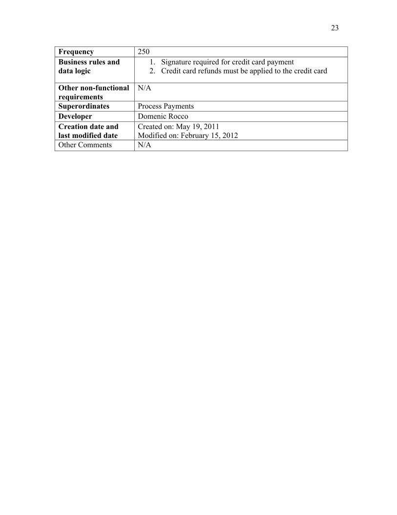
Frequency 250 Business rules and data logic
1. Signature required for credit card payment 2. Credit card refunds must be applied to the credit card
Other non-functional requirements
N/A
Superordinates Process Payments Developer Domenic Rocco Creation date and last modified date
Created on: May 19, 2011 Modified on: February 15, 2012
Other Comments N/A

24
Use Case 016: Manage Prescriptions – Sarah Slough USE CASE # 016 USE CASE Name Manage Prescriptions ACTOR Doctor Goal (1 phrase) To write a prescription for a patient and add it to the patient’s
medical history Overview and scope This use case is solely for accessing a patient visit and writing a
prescription for that patient. It includes editing prescriptions and adding prescriptions, but will not include deleting prescriptions, so to maintain all previous prescription history. It does not include accessing the patient file. The doctor will already be in the patient file when beginning the use case.
Level Primary Preconditions A doctor must be logged in.
A doctor must have selected a patient and be on a Patient Information Window.
Postconditions At prescription must be confirmed for a patient visit Instructions for prescription usage have been recorded. Date of prescription has been stored. Prescription ID has been generated by the system and stored. The patient prescription must be confirmed or updated Prescription and patient were connected Prescription and visit were connected
Trigger The patient had an visit that necessitated a prescription Included Use Cases Login, Manage Patient Extending Use Cases none MAIN SUCCESSFUL SCENARIO in numbered sequence
Actor Action System Action 1. Actor logs on. 2. INCLUDE Login 3. Actor enters patient file 4. INCLUDE Manage Patient 5. System displays available
options to doctor (Manage Referrals, Manage Prescriptions, Create Diagnosis)
6. Actor selects Manage Prescriptions
7. System displays available patient visits.
8. Actor selects a patient visit.
9. Systems prescription options including Edit Prescription and Add Prescription.
10. Actor selects add new prescription
11. System displays new prescription form.
12. Actor enters prescription information.
13. System displays prescription information

25
14. Actor confirms prescription
15. System confirms prescription and displays information with generated ID number.
OTHER SUCCESSFUL SCENARIOS (Specify any successful variations of the normal execution path, including any extension points using EXTEND eus_name)
Step Branching Action 10 a. Actor selects edit prescriptions
System displays prescriptions available for editing
12 a Actor does not enter in prescription information
A message is displayed prompts the actor to enter prescription information.
UNSUCCESSFUL SCENARIOS (erroneous situations)
Conditions Actions *a Actor chooses cancel
Aborts the manage prescription transaction, displays cancellation message and returns to doctor’s main login page.
13a Actor tries returning to main page without confirming prescription
A message pops up warning the doctor that the prescription has not been confirmed and will be deleted if he/she proceeds.
12a Actor tries writing in a prescription that is already on file for the patient.
System warns actor that it is a duplicate prescription and offers to take the actor to edit the similar prescription.
Priority in scheduling Primary Frequency Approximately 10 times a day. Business rules and data logic
The system must be able to handle any number of prescriptions per patient. Prescriptions are automatically associated with the appointment date unless updated later. Prescriptions are automatically associated with the patient for the corresponding appointment selected. The system will track all prescriptions ever written for a patient, so prescriptions cannot be deleted.
Other non-functional requirements
The Appointments page will list appointments for the logged in doctor only.
Superordinates none Developer Sarah Slough Creation date and last modified date
Created 5/20/2011 Last modified 6/7/2011
Other Comments I considered detailing the process of accessing a patient’s
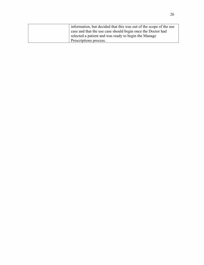
26
information, but decided that this was out of the scope of the use case and that the use case should begin once the Doctor had selected a patient and was ready to begin the Manage Prescriptions process.

27
3.5 Discussion
We went through many iterations of our Use Case Diagram throughout the course of the project. Our first step was to decide on actors. We obviously wanted to include the Medical Staff. We decided to include doctor as a specialization of Medical Staff. All Medical Staff have the basic medical system goals of searching and managing medical history, managing exam notes and adding an initial medical history, but Doctors have the additional goals of creating diagnoses and referrals and managing prescriptions. The Administrator, a Doctor, will also have a goal of managing users and privileges. All Staff members share the basic use cases as shown in the diagram and the description.
We debated several points in the creation of our use case diagram. We considered
having “Search Medical History” be an included use case in “Manage Medical History”, but decided that this may be done separately as a primary use case. We also considered including or extending “Add Initial Medical History” in “Manage Medical History”, but decided against this because it will entail a separate process and may be done separately. “Manage Medical History” will frequently occur without adding an Initial Medical History. We also considered making “Create Diagnosis”, “Create Referral” and “Manage Prescriptions” extended use cases of “Manage Medical History”, but decided that Doctors will likely just access these through patient and then patient visit instead of first looking at a whole patient history. “Manage Medical History”, as we envision it, is for viewing patient history and editing their initial medical history, not for creating prescriptions, referrals and diagnoses, though these may be viewed in the medical history. Prescriptions, referrals and diagnoses will be stored with patient visits, so will come up when searching patient history, but history does not need to be accessed in order to perform their use cases. We also considered adding a use case “Patient Lookup”, but decided that this is actually a part of the “Manage Patient” use case. While “Manage Patient” is a primary use case, it is also an included use case in many other use cases, including “Create Diagnosis”, “Create Referral”, “Manage Prescriptions”, “Process Payments, and “Submit Insurance Claim”. For those use cases for which we did a complete use case description, we included “Manage Patient” as a precondition. We initially had lines including “Manage Patient” and “Login”, but since they are primary use cases, we only cited them in preconditions for our individual use case descriptions. We also considered making insurance a form of payment, but decided that “Submit Insurance Claim” would be a separate use case because it did not involve processing a patient payment. Finally, we considered adding a separate staff specialization, “Office Staff” that handled all of the administrative use cases but decided that any other staff member should be able to share these as goals as well. We also considered adding a staff actor “Nurse” since nurses will primarily handle exam notes, but decided that this use case would also occasionally be handled by a Doctor, so included it as a use case for all Medical Staff.
Our many debates aside, we were united on making the use cases as simple and
unified as possible. We did not users to have to go through different sequences of actions to perform slightly different tasks in a patient file or in a payment screen. To eliminate redundancy and ensure friendly user interface, we decided that “Manage Patient” would

28
be the way to access most other steps. We allowed for most staff to be able to do most of the basic use cases with only doctors and medical staff, with higher privileges, to make changes to patient medical history. In addition to simple user interface, we also wanted data to be able to be accessed from multiple “routes” (through Patient or through Visit, for example), so we created general use cases that would allow for multiple class interaction once we began on the Class Diagram.
29
4. Class Model
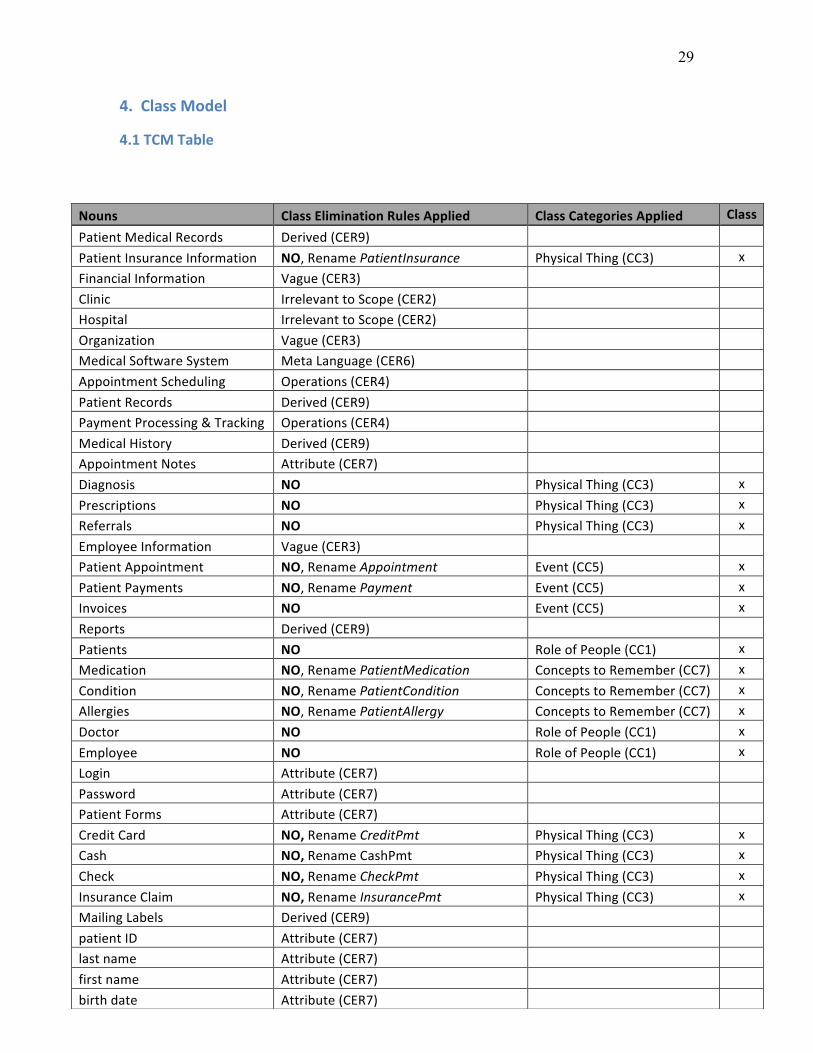
4.1 TCM Table
Nouns Class Elimination Rules Applied Class Categories Applied Class
Patient Medical Records Derived (CER9) Patient Insurance Information NO, Rename PatientInsurance Physical Thing (CC3) x Financial Information Vague (CER3) Clinic Irrelevant to Scope (CER2) Hospital Irrelevant to Scope (CER2) Organization Vague (CER3) Medical Software System Meta Language (CER6) Appointment Scheduling Operations (CER4) Patient Records Derived (CER9) Payment Processing & Tracking Operations (CER4) Medical History Derived (CER9) Appointment Notes Attribute (CER7) Diagnosis NO Physical Thing (CC3) x Prescriptions NO Physical Thing (CC3) x Referrals NO Physical Thing (CC3) x Employee Information Vague (CER3) Patient Appointment NO, Rename Appointment Event (CC5) x Patient Payments NO, Rename Payment Event (CC5) x Invoices NO Event (CC5) x Reports Derived (CER9) Patients NO Role of People (CC1) x Medication NO, Rename PatientMedication Concepts to Remember (CC7) x Condition NO, Rename PatientCondition Concepts to Remember (CC7) x Allergies NO, Rename PatientAllergy Concepts to Remember (CC7) x Doctor NO Role of People (CC1) x Employee NO Role of People (CC1) x Login Attribute (CER7) Password Attribute (CER7) Patient Forms Attribute (CER7) Credit Card NO, Rename CreditPmt Physical Thing (CC3) x Cash NO, Rename CashPmt Physical Thing (CC3) x Check NO, Rename CheckPmt Physical Thing (CC3) x Insurance Claim NO, Rename InsurancePmt Physical Thing (CC3) x Mailing Labels Derived (CER9) patient ID Attribute (CER7) last name Attribute (CER7) first name Attribute (CER7) birth date Attribute (CER7)
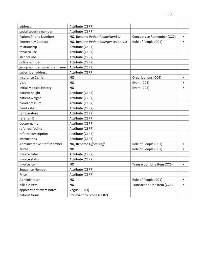
30
address Attribute (CER7) social security number Attribute (CER7) Patient Phone Numbers NO, Rename PatientPhoneNumber Concepts to Remember (CC7) x Emergency Contact NO, Rename PatientEmergencyContact Role of People (CC1) x relationship Attribute (CER7) tabacco use Attribute (CER7) alcohol use Attribute (CER7) policy number Attribute (CER7) group number subscriber name Attribute (CER7) subscriber address Attribute (CER7) Insurance Carrier NO Organizations (CC4) x Visit NO Event (CC5) x Initial Medical History NO Event (CC5) x patient height Attribute (CER7) patient weight Attribute (CER7) blood pressure Attribute (CER7) heart rate Attribute (CER7) temparature Attribute (CER7) referral ID Attribute (CER7) doctor name Attribute (CER7) referred facility Attribute (CER7) referral description Attribute (CER7) instructions Attribute (CER7) Administrative Staff Member NO, Rename OfficeStaff Role of People (CC1) x Nurse NO Role of People (CC1) x Invoice total Attribute (CER7) Invoice status Attribute (CER7) Invoice Item NO Transaction Line Item (CC6) x Sequence Number Attribute (CER7) Price Attribute (CER7) Administrator NO Role of People (CC1) x billable item NO Transaction Line Item (CC6) x appointment exam notes Vague (CER3) patient forms Irrelevant to Scope (CER2)

31
4.2 Analysis Class Diagram
4.3 Selected Class Definitions Selected Class Definitions Referral: Referral is a patient referral to an outside doctor or to an outside facility. This may be done when special services or specialists are needed. Prescription: Patient prescriptions are written by doctors. They include the medicine name and specific instructions for use as well as the date prescribed. Prescriptions are different from medication because they are only prescriptions written by the clinic and do not include previous medications, medications prescribed by other doctors or over-the-counter medications taken by the patient. Diagnosis: Diagnoses are created by the doctor using diagnosis codes, date and description of diagnosis. These differ from patient conditions because they are only diagnoses created by the clinic.

32
InitialMedicalHistory: Initial Medical History is gathered at the time of the patient’s first visit, but may be updated at later visits if information has changed. It includes a historyID, current tobacco use, alcohol use, drug use and the related classes PatientCondition, PatientMedication and PatientAllergy. PatientCondition: These are any condition provided by the patient that existed prior to visiting the clinic or that have been observed or diagnoses by other doctors. PatientCondition does not include diagnoses by the clinic. PatientMedication: PatientMedications include over-the-counter medications and any other medicine prescribed for the patient by an outside doctor. PatientAllergy: PatientAllergy is any allergy the patient may have. It is provided during the Initial Medical History, but may be updated later. Visit: Visit is the actual patient visit, with or without an appointment along with the basic exam notes. “Time” is a date/time attribute. Appointment: Appointment is the “reservation” for the patient visit. Insurance Payment: Insurance Payment acts differently than the other types of payments. It is not included in the Process Payment use case because that scope is restricted to patient payments. Insurance claims are submitted and payment is received later. Patient Insurance: Patient insurance is the data for the patient’s insurance policy. It also includes whether the insurance policy is active since a patient may have previous or alternative insurance policies.
4.4 Selected Association Definitions Referral/Prescription/Diagnosis:Patient, Doctor and Visit: Each patient and patient visit may have zero or many referrals, prescriptions and diagnoses. Each referral/prescription/diagnosis will only belong to one patient. Visit:Invoice: A visit will have at least one invoice, but may have many if different types of services were rendered. An invoice will only be for one visit. Payment:Invoice A payment will be for at least for one invoice, but may be for many if there are may unpaid invoices.
33
4.5 Discussion
Our initial approach to developing our class diagram began with a group discussion of the conceptual classes. Using the project requirements and use case diagram, we were able to establish the more obvious classes – people (Employee, Administrator, Doctor, Nurse, OfficeStaff, Patient and PatientEmergencyContact), transactions/events (Appointment, Payment, Invoice and InitialExam) and physical items (PatientInsurance, Diagnosis, Prescription, Referral, Credit Card, Cash, Check and Insurance). These classes constituted the majority of the classes within our diagram. Once we had established the body of the class diagram, we added the associated attributes. Any multi-valued attributes were converted to classes, such as PatientPhoneNumber, PatientAllergy, PatientCondition and PatientMedication. Next, we identified the less obvious classes by “walking-through” the use case scenarios. We were able to establish two additional classes, InsuranceCarrier and InvoiceItem, which had to be derived from their respective parent classes, PatientInsurance and Invoice. We chose to include these two classes because they included extended information that couldn’t be represented in their parent classes. BillableItem was a class that was further derived from InvoiceItem in a later iteration as the invoicing process was further explored.
As a secondary measure, we followed up our discussion by working through the
class identification and elimination procedures outlined by the TCM methodology. No additional classes were found through the TCM process; however it did affirm our original class designations. The table is included at the end of this discussion.
One of the difficulties we ran into during the class modeling process was deriving
classes from the use case diagram. The process of thinking about the use cases in terms of classes and their relationships brought on a lengthy group discussion how and where particular class attributes would be accessed from the system. In some instances, the use cases (e.g. Manage Patient) would entail attributes being pulled from multiple classes. This led to some initial confusion about how the classes related to each other. We overcame this obstacle by running through the scenario step by step to establish the progression of information through the system. In reviewing our class diagram after its initial submission, we also decided to add the “Visit” class, so that “Appointment” would be designated as the “reservation” for a visit. We also had considerable discussion about whether the actors in our use case diagram needed to match the classes in our class diagram. Ultimately, we decided that while we had more general actors in our use case diagram, in our class diagram, we would further specify employee classes since we wanted certain employee subclasses to be specifically associated with other classes even if other staff members were technically able to execute the use case. For example, an Office Staff member will process a payment or make an appointment, even though other staff members are able to perform this role according to our use case diagram.
Another challenge that our team faced was limiting the scope of the system. We
found that it was easy to add classes that may not be necessary. It became tempting to add classes rather than limiting them to attributes. Our group used the general rules for

34
class identification to distinguish the items which stood out enough to be considered their own class and which were better kept as attributes.
The approach that our team took to develop this class diagram was successful in
our opinion. We enjoyed first thinking about scenarios and their attributes from a conceptual perspective and then following up our discussion by "checking" our results with the more analytical TCM methodology. By combining the two approaches, we were able to gain both a broad and narrow view of the PCCS system.
As a suggestion, we believe the methodology could be improved upon if there
could be some sort of rule of scope. The system boundaries are generally vague and it is easy to see the scope size creep larger and larger with every class in question. While we constantly referred back to the requirements, we felt that we could use some more strict rules to limit scope creep.
35
CHAPTER 2: System Design
5. Sequence Diagrams
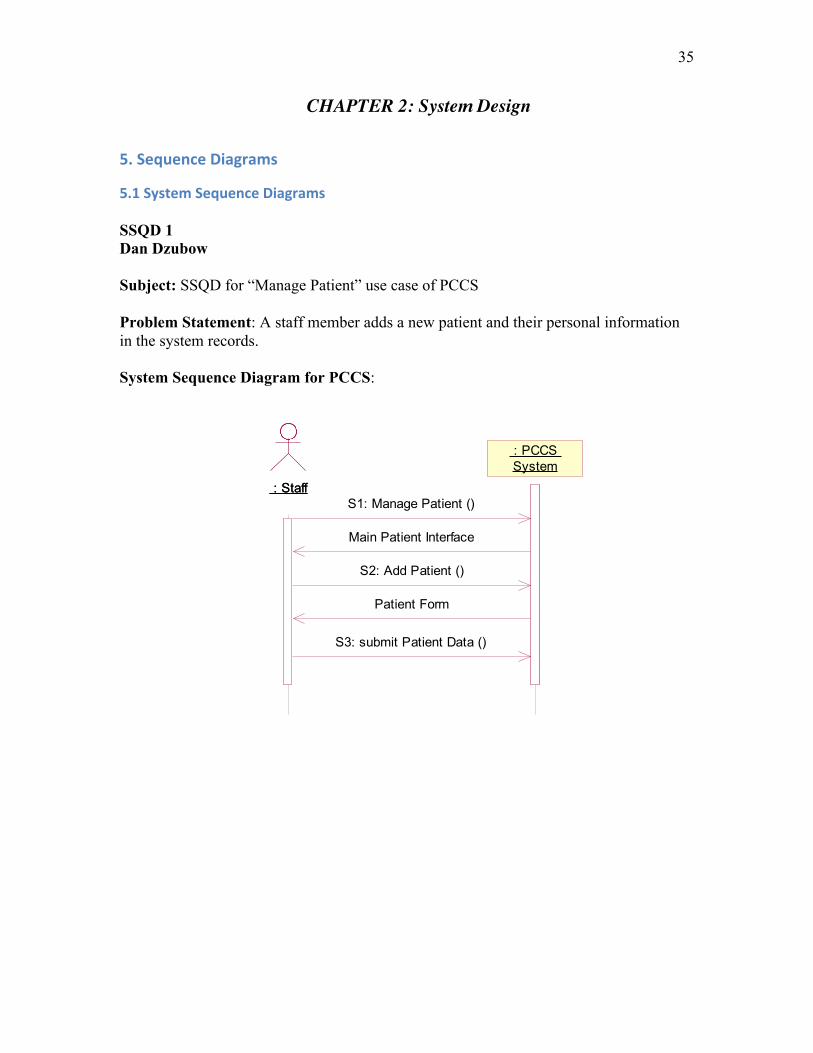
5.1 System Sequence Diagrams SSQD 1 Dan Dzubow Subject: SSQD for “Manage Patient” use case of PCCS
Problem Statement: A staff member adds a new patient and their personal information in the system records.
System Sequence Diagram for PCCS:
: Staff : Staff
: PCCS System : PCCS System
S1: Manage Patient ()
S2: Add Patient ()
Patient Form
S3: submit Patient Data ()
Main Patient Interface

36
SSQD 2 Domenic Rocco
Subject: SSQD for “Process Payments” use case of PCCS
Problem Statement: The staff receives a cash payment from a patient for their visit.
System Sequence Diagram for PCCS:
: Staff : Staff : PCCS System : PCCS System
S1. initPaymentSequence()
patient invoice list
S2. selectInvoice()
invoice data
payment form
S3. enterPaymentData()
payment result

37
SSQD 3 Sarah Slough
Subject: SSQD for “Manage Prescriptions” use case of PCCS
Problem Statement: A doctor adds a new prescription to a patient visit
System Sequence Diagram for PCCS:
confirmed prescription ID()
: Doctor : Doctor
:PCCS:PCCS
S1: manage prescriptions()
available patient visits
S2: select visit ID()
prescription options
S3: add prescription()
prescription form
S4: enter prescription data()
prescription
S5: Confirm prescription()

38
5.2 Sequence Diagrams and Individual Validation and Discussion SQD 1 Dan Dzubow Subject: SQD for “Manage Patient” use case of PCCS
Problem Statement: A staff member adds a new patient and their personal information in the system records.
Sequence Diagram for PCCS:
: Staff : Staff : System Interface : System Interface : System Handler : System Handler : Main Patient Interface : Main Patient Interface
: Patient Handler : Patient Handler
: Patient Form Window : Patient Form Window
: Patient Form Handler : Patient Form Handler : Patient : Patient
: Patient Emergency Contact
: Patient Emergency Contact
: Patient Phone Number : Patient Phone Number : Patient Insurance : Patient Insurance : Insurance Carrier : Insurance Carrier
S2: add Patient ()
S1: ManagePatient ()
create ()
display Main Patient Interface ( )
create ()
S3: submit Patient Data ()
diplay Patient Form ()
create ()
save Patient ()
modify last_update (time, date)
create ()
createPatientEmContact ()
createPatientPhoneNo ()
createPatientInsurance ()
display Patient Data ()
getInsuranceCarrier ()

39
Manage Patient Validation and Discussion
- The first step in the process would be to login to the PCCS System (INCLUDE Use Case Login). This would be done by entering the username and password and clicking the ‘Login’ button. The user would be taken to the main System Interface.
- S1. On the main System Interface, there would be a tab labeled ‘Patients’. The staff member would select this tab, which would bring up the main Patient Interface.
- S2. To enter a new patient into the system, the staff member would click the ‘Add Patient’ button.
o The system would respond by opening a black patient form with data fields corresponding to the patient’s personal information.
o (Alternate Scenario) The sequence diagrams reflect the course of action taken for adding a new patient into the system. Editing an existing patient is also handled in this use case, and primarily follows the same sequence. To edit an existing patient’s personal information, the Actor would select the patient after a search in the patient database (either by patient name or patientID). The most current personal form would be opened for editing.
- S3. Using the completed paperwork provided by the patient, the staff member would proceed to fill in the corresponded data fields in the patient information.
o After the staff member has completed filling in or editing the patient form, they would click the ‘Submit’ button.
Upon submission, a unique patientID would be generated to identify the patient in the system.
Simultaneously, the system will save the form along with the date and time it was created (or modified in Alternate Scenario).
The system will then return the user to the Main Patient Interface.
I found the SQD creation process to be very challenging. With little experience in the software/database development fields, I had trouble visualizing what entities, windows and messages should be included as well as the sequence in which they would be accessed or created. Although I could follow the logic behind the text and homework examples, it was a challenge to translate the process into a system I was unfamiliar with.
The initial iteration of the sequence diagram did not include the system interface or the patient form window. The classes PatientEmergencyContact, PatientPhoneNumber, PatientInsurance and InsuranceCarrier were also originally missing from the SQD, as I mistakenly included them in the physical process of entering patient data. In the final iteration, this mistake was corrected by adding these entities as objects that were created by the patient object when their corresponding data is entered into the patient form.
Another challenge that I faced in creating this diagram was what to do with the unique identifying attribute that would need to be created for each new Patient entity. I wanted to show that the system would generate the patientID when a Patient entity was

40
first created. However, I placed the patientID as part of the message to display the Patient Form. The problem with the patientID being created this early in the process was that if a patient form was begun but cancelled before being complete, the system would have created a patient entity with patient ID but nothing else. By waiting to create the PatientID when the patient entity is being submitted into the patient database, it guarantees that each PatientID will be assigned to a valid patient.
Once the substance of the diagram was in place, the final iteration of the sequence diagram involved formalizing the names of the operations in order to match the design class diagram.

41
SQD 2 Domenic Rocco Process Payment
Subject: SQD for “Process Payments” use case of PCCS
Problem Statement: The staff receives a cash payment from a patient for their visit.
Sequence Diagram for PCCS:
: Staff : Staff : Patient Window : Patient Window
: Payment Window : Payment Window : Process Payments Handler
: Process Payments Handler
: Patient Handler : Patient Handler : Visit : Visit : Invoice : Invoice : Payment : Payment : CashPmt : CashPmt
S2. selectInvoice()
getInvoice()
S1. initPaymentSequence()
create()
getVisits()
getInvoices()
calculateBalance()
getInvoiceStatus()
display invoice data
invoice loop
visit loop
displayInvoice()
S3. enterPaymentData(method, amount)
updateInvoice()
calculateBalance()
getInvoiceStatus()
display updated invoice data
create()
create()
[Payment.method = 'cash'] createCashPmt()

42
Process Payments Validation and Discussion • The process payments use case begins after the staff is already logged into the
system and a patient has already been selected. • S1. From the patient window, the staff first initiates the payment sequence by
choosing “Make a Payment” from the menu. o When the payment sequence has been initiated, the system retrieves a list
of the selected patient’s invoices. For each patient visit, data from one or more invoices that are
associated with the visit are listed on the patient window. Data listed includes the invoice number, date, balance, and status (open/paid).
• S2. The staff selects the invoice from the list that the patient wants to pay. This brings up the payment form.
• S3. The staff enters the payment method and amount and submits the form, which creates the payment object and payment type object (cash, credit, or check). The system then displays the updated invoice data.
o The sequence diagrams reflect the course of action taken for processing a payment made in cash.
o Payment by check will mostly follow the same sequence, except that the check number and the name of the bank which the check is drawn on will also be required. The checkPmt object will be created in lieu of the cashPmt object.
o Payment by credit card will also mostly follow the same sequence, except that credit card data will be required, which can be input via swiping the credit card through the credit card reader or by manual entry. The creditPmt object will be created in lieu of the cashPmt object.
Previous iterations of the sequence diagram excluded the patient window and its handler. The initialize payment sequence message (S1) was originally being sent directly to the payment window. I realized that the sequence actually began from the patient window. It is only after a patient invoice has been selected that the payment window appears. A more formal naming convention of operations was also instituted in more recent iterations, so that operation names could match those present on the design class diagram.

43
SQD 3 Sarah Slough Manage Prescriptions
Subject: SQD for “Manage Prescriptions” use case of PCCS
Problem Statement: A doctor adds a new prescription to a patient visit
Sequence Diagram for PCCS:
: Doctor : Doctor : Main Patient Window : Main Patient Window : Prescription Handler : Prescription Handler : Patient Visit Window : Patient Visit Window : Visit : Visit : Prescription Form Window : Prescription Form Window : Prescription : Prescription
S1: select manage prescript...
create()
display visit()
display visit()
S2: select visitID()
display selected visitID()
S3: add prescription()
create()
display prescription form()
S4: enter prescription data(name, instructions, date)
S5: confirm prescription()
store prescription(prescriptionID, name, instructions, date)
display confirmed prescription ID()
loop

44
Manage Prescriptions Validation and Discussion
• The Manage Prescriptions use case begins after a doctor has logged in and accessed a patient file.
• S1. From the Main Patient Window a doctor will see all options available for that patient including “Manage Prescriptions”.
o The doctor selects Manage prescriptions, which then retrieves that patient’s visits and displays the visits in the Patient Visit Window.
• S2. The doctor will select a visit ID from the list of available visits. o The displayed visit ID will show prescription options for that visit
including ‘Edit Prescriptions’ and ‘Add Prescription’. • S3. The doctor selects ‘Add Prescription’, which will then bring the doctor to
the Prescription Form Window displaying the prescription form. • S4. The doctor enters the prescription data minus the system-generated
prescription ID. o The prescription is then created. o The doctor confirms the prescription entry and the prescription is
stored with a system-generated prescription ID. o The confirmed ID and prescription are then displayed.
I went through many iterations of my sequence diagrams, especially with the SQD, which would then lead to additional changes in my SSQD. My first change was that I had initially looped the process of selecting a visit and adding a prescription. I decided to take out the loops because my scenario is only for adding one prescription. I instead added a loop around display visit() because a patient may have multiple visits that need to be displayed. I also considered showing the process of selecting a patient file, but decided that this would really be an included use case, Manage Patient. Manage Patient details the process of accessing a patient file in one scenario for patient lookup, so instead of repeating these steps in most use cases, we discussed as a group that we would make it an included use case. I also toyed with how I would show the system returning the generated prescription ID. Since the prescription ID is not an entity, I do not need to retrieve it, so instead just had it returned from the system after the prescription was stored. I decided that nothing else needed to be shown in the diagram.
Perhaps the biggest problem I faced was whether or not to include a second
handler after the Patient Visit Window. According to the ten heuristics, another control object should be created, but since I have so few entities, I decided to have the Patient Visit Window interact directly with the entities like in the Restaurant Order System example we reviewed in class.
I feel quite confident with the concepts behind the sequence diagrams, but as I
observed in comparing my diagram with my teammates’, we all have slightly different styles. I think this is something that will be found in most software development teams as people understand the system differently, but I also feel that learning best practices in diagramming will be an ongoing process. I think my diagram makes sense logically and that after my revisions it correctly shows the process of adding a patient prescription.

45
5.3 Validation and Discussion
Individual validation and discussion can be found under the individual SSQDs and SQDs. Throughout the development of our sequence diagrams, we frequently discussed our methodology with each other to ensure that we all understood the system in the same way. While each of our diagrams detailed a different use case, we wanted to be sure that we all similarly understood the steps an actor would take to access each use case. This was especially crucial for Process Payments and Manage Prescriptions since both processes begin after a patient file has been accessed. To prevent redundancy in use case descriptions and in the sequence diagrams, we decided that Manage Patient would be an included use case for many others. This helped us in our development of sequence diagrams because we did not need to include the steps to access a patient file, but instead could begin with the specific scenario. We also worked together to simplify our sequence diagrams as much as possible so that each process did not involve too many steps. We also debated when the create() step would occur in each process. We each had slightly different design styles, but learned from each other and adapted or included some styles from other team members.

46
6. Design Class Diagram
6.1 Design Class Diagram

47
6.2 Validation and Discussion
The development of the design class diagram went quite smoothly since we had all taken the class diagram into consideration in the development of our system sequence diagrams and our sequence diagrams and the operations come from these diagrams. We debated where to put getVisits() and displayVisit() depending on what point visit retrieval occurred in the Manage Prescriptions and Process Payment use cases. We decided to put getVisits() under Patient because visits for a patient are retrieved once a patient file is accessed. DisplayVisit() pulls visit attributes and displays them for the actor. We put all create() operations in the class from which the new class instance would be created. For example, Visit is accessed to Manage Prescriptions, so createPrescription() is included in the Visit class. CreateCreditPmt(), createCashPmt(), createCheckPmt() and createInsurancePmt() are all operations of the Payment class. Most of our operations for our sequence diagrams were very straightforward. Development of the design class diagram helped us “double-check” our sequence diagrams and ensure that all classes that needed to be accessed were included in the sequence diagrams. If we would have had more time we obviously would have completed more sequence diagrams and added more operations for other use cases, which may have helped us better understand how all the operations will interact, but this was not within the scope of this project.

48
CHAPTER 3: Physical Design
7. Relational Database Schema
7.1 Relational Database Schema Employee (employeeID, ssn, login, password, fName, lName, dob, street, city, state, zip,
phone#, startDate)
Doctor (employeeID*)
FK employeeID references Employee (employeeID)
Administrator (employeeID*)
FK employeeID references Doctor (employeeID)
Nurse (employeeID*)
FK employeeID references Employee (employeeID)
OfficeStaff (employeeID*)
FK employeeID references Employee (employeeID)
Referral (referralID, name, facility, description, date, doctorID *, patientID*, visitID*)
FK doctorID references Doctor (employeeID)
FK patientID references Patient (patientID)
FK visitID references Visit (visitID)
Prescription (prescriptionID, name, instructions, date, doctorID *, patientID*, visitID*)
FK doctorID references Doctor (employeeID)
FK patientID references Patient (patientID)
FK visitID references Visit (visitID)
Diagnosis (diagnosisCode, date, description, doctorID*, patientID*, visitID*)
FK doctorID references Doctor (employeeID)
FK patientID references Patient (patientID)
FK visitID references Visit (visitID)
Patient (patientID, ssn, fName, lName, dob, street, city, state, zip, preferredDr)
PatientEmergencyContact (phone#, patientID*, fName, lName, relationship)
FK patientID references Patient (patientID)
PatientPhoneNumber (phone#, patientID*, type)
FK patientID references Patient (patientID)

49
PatientInsurance (policy#, group #, subscriberName, subscriberStreet, subscriberCity,
subscriberState, subscriberZip, isActive, patientID*, carrierID*)
FK patientID references Patient (patientID)
FK carrierID references InsuranceCarrier (carrierID)
InsuranceCarrier (carrierID, name, street, city, state, zip, phone#, fax#)
InitialMedicalHistory (historyID, tobacco_use, alcohol_use, drug_use, patientID*)
FK patientID references Patient (patientID)
PatientCondition (historyID*, description)
FK historyID references InitialMedicalHistory (historyID)
PatientMedication (historyID*, name)
FK historyID references InitialMedicalHistory (historyID)
PatientAllergy (historyID*, description)
FK historyID references InitialMedicalHistory (historyID)
Appointment (appointmentID, time, reason, staffID*, visitID*)
FK staffID references OfficeStaff (employeeID)
FK visitID references Visit (visitID)
Visit (visitID, time, height, weight, blood_pressure, heart_rate, temperature, notes,
patientID*, nurseID*, doctorID*)
FK patientID references Patient (patientID)
FK nurseID references Nurse (employeeID)
FK doctorID references Doctor (employeeID)
Invoice (invoice#, visitID*, date)
FK visitID references Visit (visitID)
InvoiceItem (invoice#*, sequence#*, name*)
FK invoice# references Invoice (invoice#)
FK name references BillableItem (name)
BillableItem (name, description, price)
Payment (paymentID, invoice#*, amount, date, method)
FK invoice# references Invoice (invoice#)
CreditPmt (paymentID*, ccType, cc#, expDate, ccName)
FK paymentID references Payment (paymentID)

50
CheckPmt (paymentID*, check#, bank_name)
FK paymentID references Payment (paymentID)
CashPmt (paymentID*)
FK paymentID references Payment (paymentID)
InsurancePmt (paymentID*, claim#)
FK paymentID references Payment (paymentID)
7.2 Discussion
Since we spent the majority of our project time revising our use case, sequence, class and design class diagrams to ensure we had a complete understanding of our system’s definitions and associations, the relational database schema proved to be relatively simple. We discussed the structure of the relational database schema as we were creating our design class diagram because many of the considerations were the same for both. Since we included primary keys for most of our classes, assigning primary keys and citing foreign keys was not difficult. Since most of our problems had been addressed in previous project sections, we did not really face any problems in the creation of the relational database schema. One problem we faced, which was quickly resolved, was the addition of a historyID in the InitialMedicalHistory relation. Our InitialMedicalHistory class did not initially include an ID, but in the development of our relational database schema, we realized that it would be helpful to have a unique primary key in this class. Adding a historyID helped us define associated relations as well. We also paid careful attention to how we labeled subclasses that are also foreign keys. For example, we added doctorID to the prescription, diagnosis and referral relations, which references the employeeID of the doctor.

51
CHAPTER 4: Evaluation of Analysis & Design
8. Evaluation of Analysis & Design
8.1 Evaluation of Project
Our group felt quite confident with the selected domain. We all have had experience in previous coursework interacting with healthcare information systems. Also, we have all been users of clinics that may need this type of system so have an additional perspective on the requirements. We also were lucky to have contacts in the healthcare industry that could provide user perspectives on a system. While our problem was, generally, to create a simple patient care system for clinic, we found that simplifying a system and data and information interaction can prove to be quite complex. We constantly referred back to our requirements to ensure we were not adding unnecessary features or missing opportunities to unify classes or better detail a use case or process sequence. Because we were constantly reevaluating requirements and previously completed sections, we felt that in the end we had a project that completely and sufficiently addressed the needs of the clinic through simple, yet elegant design. We were never afraid to make changes or reconsider previous decisions, which allowed us the flexibility to improve our design.
While we felt successful in our complete project, in design and analysis of a
system, we could always use more time and our project time was definitely limited. If we had more time, we would be able to spend more time diagramming other use cases which would help us analyze our class diagrams. We would also be able to spend more time conducting research on requirements. Because we are creating a system for a clinic that does not exist, we are not working with real requirements. If we were able to further research clinics or speak with more clinic staff members, we would be able to better understand our requirements, which would undoubtedly help the design of our system.
8.2 Evaluation of UML and Tool
The Unified Modeling Language (UML) is the de facto standard diagramming notation for drawing or presenting pictures (with some text) related to software – primarily object-oriented software (Larman, 2005). Each member of our group had gained some experience with UML by developing entity relationship diagrams in a previously taken course. We found that the notation used in developing entity relationship diagrams prepared us well for modeling class diagrams – they are strikingly similar in many ways. One of the handful of differences we noticed between ERDs and class diagrams, was that multi-valued attributes were used in entity relationship diagrams only. In class diagrams, any instance where a multi-valued attribute may have been applicable would have instead been modeled as a new class.
During this course, we were also exposed to use case and sequence diagram
modeling for the first time. While the notation was drastically different than the UML

52
notation with which we had already been familiar, we found it just as easy to learn. Deciding what would constitute a use case was a more difficult exercise than actually modeling the use case diagram itself.
Although electronic modeling was a requirement of our project, each of us had
used sketching on scrap paper at times to develop early iterations of our diagrams. We felt that this approach both captured the agile true nature of UML and demonstrated its versatility. When it was time to develop our formal diagrams, we used IBM’s Rational Rose software.
Our experience with Rose was generally positive. Compared to the alternative
modeling software, Microsoft Visio, which we had used in our previous course, we found the drawing of association lines to be an improvement. The process of adding multiplicity to diagrams was also extremely simple. We did however identify a handful of opportunities for improvement within the software.
• When working on sequence diagrams, it is not possible to change the source or
destination of object messages. If a change needed to be made, the object message would have to be deleted and added again between the desired objects. This was especially cumbersome when the object message being deleted was followed by other object messages – each subsequent message would also be deleted.
• It would have been beneficial to have entity object, control object, boundary object, and actor icons available on the sequence diagram toolbar. Instead, objects would be placed on the diagram and then have their stereotypes set in a subsequent step and actors were created on a separate screen.
• Sequence diagram messages, including return messages, are automatically assigned a sequence number by default. In order to mimic the examples from our notes, the default convention was undesirable. We were only able to figure out how to disable this feature through an external resource.
• The version of Rose we had installed offered no documentation. It would have been helpful to have access to a help file within Rose and not have had to search for external resources on the web.

53
REFERENCES Dzubow, L. (2011). Personal communication with medical practice owner. IBM Rational Support Resources. Retrieved from: http://www-01.ibm.com/support/docview.wss?uid=swg27020747 Larman, C. (2005). Applying UML and Patterns, 3rd Edition. New Jersey: Prentice Hall. Song, I. (2011). Class Lectures.
54
APPENDIX
9. Appendix
9.1 Lessons Learned Daniel Dzubow
One of the most valuable lessons that I will take away from this project is that I better understand the agile methodology of development. Although I have understood its meaning and its benefits through reading the textbook, I found it more beneficial to apply it firsthand. Iterative design development feels natural and allows for the design to take shape as the team members discover what does and doesn’t work. This process also allowed me to get acclimated with all of the components involved with UML in analysis and design. I found the inter-connectivity between requirements and diagrams to be a challenge to grasp, but with time, I was able to better recognize the logical flow as the design grew from requirements and analysis to system design to physical design.
Another lesson I learned best through this exercise is the importance of
understanding your client and their needs. While we didn’t have a tangible client to interact with, we were able to use our creativity and personal experiences in medical offices to come up with realistic goals and requirements for the system. However, no amount of research can substitute for dealing with a stakeholder in person. Their knowledge of the industry and deep understanding of the intricacies of their business would help infinitely towards the design of the system. Domenic Rocco
Prior to taking this course and working on the term project, I gained some experience developing websites using ASP.Net. My knowledge of web development was acquired through individual research at my leisure, not through schooling or formal education in software development. While I was always able to come through and produce the desired result, I learned that my approach was not as agile as it could have been. After becoming more familiar with classes during this course and throughout my work on the term project, I realized that there were many opportunities for improvement in my past projects.
Through my work on these past projects, I gained an appreciation for reusability,
which as I later learned was a fundamental principle of agile methodologies. To me, reusability used to mean being able to copy and paste a code to an ASP.Net code-behind page and then editing the variables contained within. While I found this approach to be more manageable than starting from scratch, I know now that a greater level of agility could have been achieved by developing classes and classes that also included operations. In addition, I now see value in creating classes to correspond with database entities. My past projects have included web forms that enabled a site administrator to manage employee, news, and event listings, among other things on a website. Developing a class for an employee, for example, would have allowed me to specify the composition of an

55
employee and create operations that incorporated SQL insert, update, and delete commands. This approach would have allowed me to achieve a greater level of agility and to keep even more code out of web and code-behind pages that typically featured lengthy SQL commands.
Modeling with UML is also an excellent way to illustrate system requirements or the requirements of some specific procedure. The use case diagram is undoubtedly the best method I have been exposed to for showing the requirements of a system. In sequence diagrams, a use case is broken down and illustrates system input, system output, and the operations required to produce the desired result. In the future, I intend to use UML modeling to plan projects. Sarah Slough
I wish I had more time to implement all that I have learned this quarter in our PCCS project, but like any software development analysis and design project, we must adhere to a timeline. While I, of course, I technically learned about UML and object-oriented principles from our lectures and the textbook, I found the most valuable lessons learned were less tangible. While our development cycle was a bit different given due dates for homework assignments and assignment requirements, we still constantly referred back to our initial proposal and later assignments. It is quite impossible to complete all of these tasks in a linear manner. We found that after each assignment, we would go back through the remainder of the project to ensure that each section matched the requirements and had a similar organization. We also found ourselves altering the initial requirements as we learned more about our system and about potential user needs.
I also learned that while UML and object-oriented analysis and design has its
rules and methodologies, depending on an engineer’s or analyst’s perspective and style, it may be implemented in different ways. There are so many variations in a system’s development and organization that the UML diagrams and system design will vary depending on the team members. So, it is crucial that throughout the analysis and design process, team members engage in documentation of each step and each diagram to ensure that methodology and logic is understood by an outsider.
As I hope to work with digital libraries in my future career, this course has armed
me with a language and resources with which to approach analysis and design of cataloging and organizational software. Most importantly, perhaps, it has taught me how to think differently about the process of analysis and design, an invaluable skill that will translate to many projects and many different career roles.

56
9.2 Division of the work among members The following is the breakdown for task assignment for our project. While individuals led different sections, each team member had equal input on all portions of the assignment and we thoroughly discussed each section. Introduction Sarah Slough CHAPTER 1: System Analysis
(1) The Problem Statement Sarah Slough (2) Requirements
2.1 Functional Requirements Sarah Slough 2.2 Data Requirements Sarah Slough 2.3 Business Plan and Logic Dan Dzubow 2.4 Non-Functional Requirements Domenic Rocco 2.5 Other Important Assumptions Domenic Rocco
(3) Use Case Model
3.1 Actors and their Goals Sarah Slough 3.2 Use Case Diagram Sarah Slough 3.3 Overview Section of Use Cases Sarah Slough 3.4 Use Case Description for Primary Use Case All 3.5 Discussion Sarah Slough
(4) Class Model
4.1 TCM Table and Methodology Dan Dzubow 4.2 Analysis Class Diagram Domenic Rocco 4.3 Selected Class Definitions Sarah Slough 4.4 Selected Association Definitions Sarah Slough 4.5 Discussion Dan Dzubow
CHAPTER 2: System Design
(5) Sequence Diagrams
5.1 System Sequence Diagrams All 5.2 Sequence Diagrams All 5.3 Validation and Discussion Sarah Slough
(6) Design Class Diagram
6.1 Design Class Diagram Domenic Rocco 6.2 Validation and Discussion Sarah Slough

57
CHAPTER 3: Physical Design
(7) Relational Database Schema
7.1 Relational Database Schema Dan Dzubow 7.2 Discussion Sarah Slough
CHAPTER 4: Evaluation of Analysis & Design
(8) Evaluation of Analysis & Design
8.1 Evaluation of Project Sarah Slough 8.2 Evaluation of UML and Tool Domenic Rocco
References All Appendix
(9) Appendix
9.1 Lessons Learned All 9.2 Division of the work among members All 9.3 Unsolved Problems All

58
9.3 Unsolved problems
We were able to work through most of our problems by discussing them as a group and referring back to the text, reading and lectures. We felt it was important to address problems as they were discovered and to seek out answers, whether by contacting the professor or looking to other resources. While we do not have any unanswered questions as such, we all feel that understanding best practices in analysis and design is an ongoing process. The sequence diagrams were definitely the most difficult for us, but after extensive reevaluation, we felt that they were in their best form upon submission of the project. While we have no outlying questions, we continue to seek better understanding of what we’ve learned and hope to learn how our project could have been even better. CERTIFICATION We certify that:
• This assignment /paper/project/exam is entirely our own work. • We have not quoted the words of any other person from a printed source or a
website without indicating what has been quoted and providing an appropriate citation.
• We have not submitted this submission to satisfy the requirements of any other course.
Signature: Dan Dzubow, Domenic Rocco, Sarah Slough Date: 6/8/2011