Embed Size (px)
Citation preview
4/26/2013
1
ACI WEB SESSIONS
Analysis and Design Issues in Liquid-Containing Concrete
Structures
ACI Fall 2012 ConventionOctober 21 – 24, Toronto, ON
ACI WEB SESSIONS
Armin Ziari is a Structural Engineer at Candu Energy Inc., ON, Canada. He received his BSc from University of Tehran, Tehran, Iran, in 2004; and his MSc and PhD from Ryerson University in 2007 and 2011, respectively. He is a member of subcommittee N287.3, Design Requirements for Concrete Containment Structures for CANDU Nuclear
Power Plants. His research interests include crack and leakage control, and non-linear finite element modeling of RC members.
By
Armin Ziari, M. Reza Kianoush, R. ProticPresenter: Armin Ziari
Ryerson University & Candu Energy Inc.
Research Significance and Scope Proposed Crack Prediction Model Experimental Program Verification Design Guide Conclusions Acknowledgements
Serviceability: Deflection control, Leakage control, ...
Durability: Permeability reduction, Corrosion reduction, ...
Appearance
Simple loading conditions: Pure bending, pure tension,...
No reliable crack control for two‐way members
Ignoring repeated loading effects
Ignoring long term effects
4/26/2013
2
Experimentally investigating the cracking and leakage behaviour of two‐way panels
Using FE technique to understand different aspects of RC cracking
Developing a new analytical crack prediction model for two‐way panels
0
1
2
3
4
5
0 50 100 150 200 250
Wal
l Hei
ght (
)
Hoop Tension Force (k/)
0
1
2
3
4
5
-40 -30 -20 -10 0 10 20
Wal
l Hei
ght (
)
Vertical Bending Moment (k./)
T TM
M
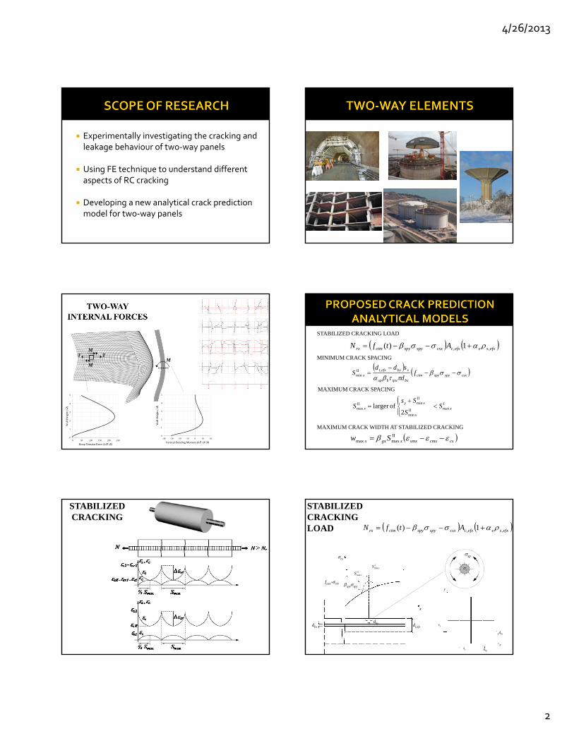
M efxseefxccsxspyspyctmrx AtfN ,, 1)(
STABILIZED CRACKING LOAD
csxspyspyctmbxtpxbsp
xbyefxtx f
d
sddS
,II
min
MINIMUM CRACK SPACING
ImaxII
min
IIminII
max 2
oflarger x
x
xy
x SS
SsS
MAXIMUM CRACK SPACING
cscmxsmxxgxx Sw IImaxmax
MAXIMUM CRACK WIDTH AT STABILIZED CRACKING
STABILIZED CRACKING
efxseefxccsxspyspyctmrx AtfN ,, 1)(
STABILIZED CRACKING LOAD
dt,efxdbx
dby
cx
x
spyspyfctm-csx
IImin xS
Imin xS r
sp
y
x
dbx
dbysy
sx
4/26/2013
3
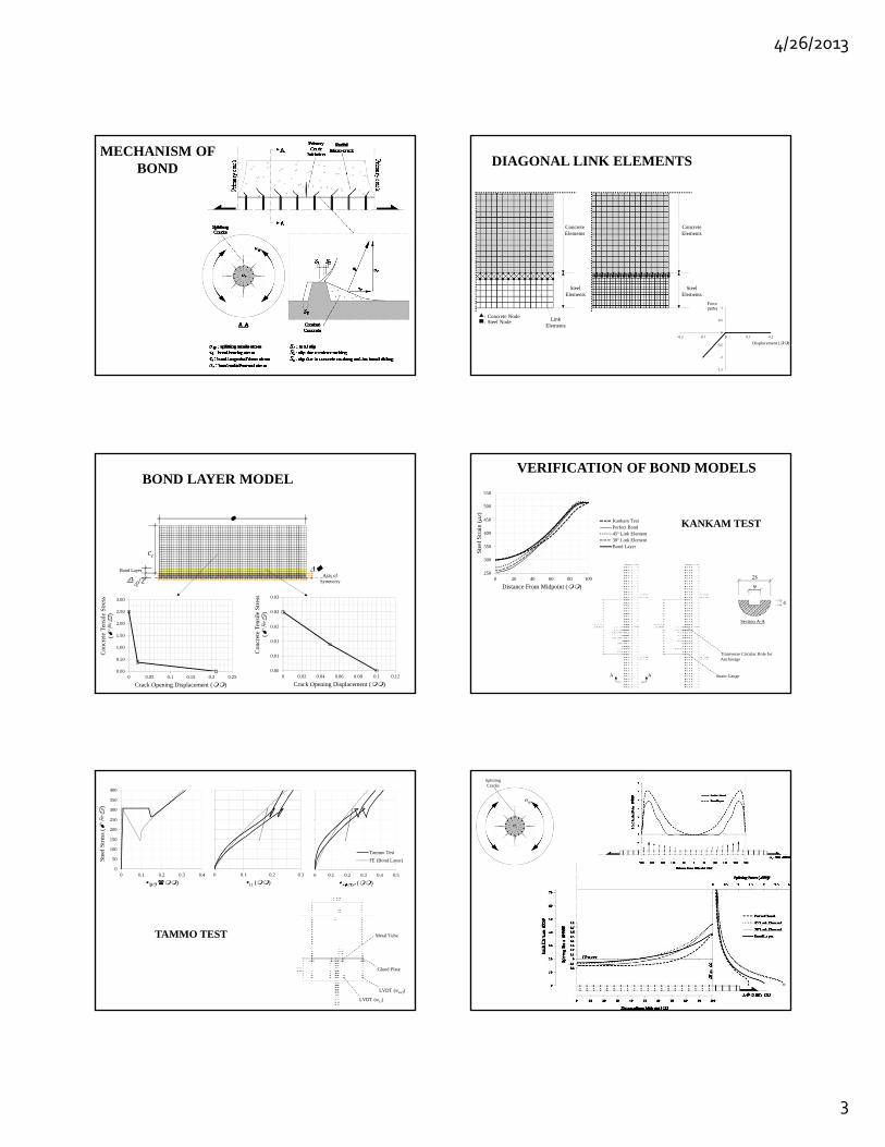
MECHANISM OF BOND
Concrete Elements
Steel Elements
Link Elements
: Concrete Node: Steel Node
Steel Elements
Concrete Elements
-1.5
-1
-0.5
0
0.5
1
-0.2 -0.1 0 0.1 0.2
Force (MN)
Displacement ()
DIAGONAL LINK ELEMENTS
0.00
0.50
1.00
1.50
2.00
2.50
3.00
0 0.05 0.1 0.15 0.2 0.25
Con
cret
e T
ensi
le S
tres
s (
)
Crack Opening Displacement ()
0.00
0.01
0.01
0.02
0.02
0.03
0 0.02 0.04 0.06 0.08 0.1 0.12
Con
cret
e T
ensi
le S
tres
s (
)
Crack Opening Displacement ()
/2
Bond Layer
Axis of
Symmetry
cc
BOND LAYER MODEL
A A
Section A-A
Strain Gauge
Transverse Circular Hole for Anchorage
250
300
350
400
450
500
550
0 20 40 60 80 100
Ste
el S
trai
n ()
Distance From Midpoint ()
Kankam TestPerfect Bond45º Link Element30º Link ElementBond Layer
VERIFICATION OF BOND MODELS
KANKAM TEST
0
50
100
150
200
250
300
350
400
0 0.1 0.2 0.3 0.4
Ste
el S
tres
s (
)
)0 0.1 0.2 0.3
11 ()0 0.1 0.2 0.3 0.4 0.5
()
Tammo Test
FE (Bond Layer)
LVDT (wsurf)
LVDT (w11)
Glued Plate
Metal TubeTAMMO TEST
r
sp
Splitting Cracks
4/26/2013
4
db/2 Bond Layer
l
uAxis of
Symmetry
cc
0
0.5
1
1.5
2
2.5
3
3.5
4
4.5
5
0 0.1 0.2 0.3 0.4 0.5 0.6 0.7 0.8 0.9 1
Rad
ial D
ista
nce
/
Splitting tensile stress /
cc = 5
100
200
300
400
-0.2
0
0.2
0.4
0.6
0.8
1
-7.5 -6 -4.5 -3 -1.5 0 1.5 3 4.5 6 7.5
Split
ting
tens
ile s
tres
s/
Bar Axis /
cc = 5
100
200
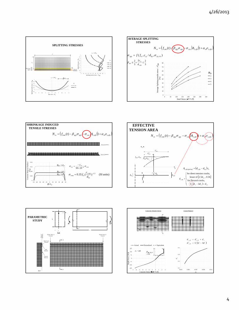
SPLITTING STRESSES
0
10
20
30
40
50
60
70
80
0 50 100 150 200 250 300 350
Ave
rage
Spl
itti
ng te
nsil
e st
ress
/
(%)
Steel Stress ()
2
3
4
5
),/,( ,crxsybycyctspy dcff
3
22
3
2
,
efxt
cyspy d
c
AVERAGE SPLITTING STRESSES
efxseefxccsxspyspyctmrx AtfN ,, 1)(
Axis of Symmetry
Axis of Symmetry
0
0.04
0.08
0.12
0.16
-50 -40 -30 -20 -10 0 10 20 30 40 50
Con
cret
e S
tres
s at
Sur
face
/
/
= 3 = 4
= 2
SHRINKAGE INDUCED TENSILE STRESSES
efxseefxccsxspyspyctmrx AtfN ,, 1)(
csoxcs
csx 61050
units) (SI )(35.0 5.1, bx
eqxcctcsox d
cf
efxseefxccsxspyspyctmrx AtfN ,, 1)(
EFFECTIVE TENSION AREA
dt,efxdbx
dby
cx
x
spyspyfctm-csx
IImin xS
Imin xS
xbyefxtefxc sddA ,bar)(per ,
cxxxtx
cxefxt
dkddk
hdd
cracks, flexuralfor
5.0 , 5.2 oflesser
cracks,sion direct tenfor
,
Bond Layer Elements
Steel Elements
Concrete Elements
A
AA-A
Pla
ne o
f S
ymm
etry Weaker Plane of
ConcreteWeaker Plane of
Concrete
PARAMETRIC STUDY
Concrete Tensile Stress Crack Pattern
A
A
kd
-225
-150
-75
0
75
150
225
-7 -6 -5 -4 -3 -2 -1 0 1 2 3
Dep
th A
xis
(
)
Concrete Stress )
Actual Normalized Equivalent
= 156
= 240
0.2
0.3
0.4
0.5
0.003 0.005 0.007 0.009 0.011
k't
s
kddkd
ddd
teft
cefteft
,
,,

4/26/2013
5
dt,efxdbx
dby
cx
x
spyspy
fctm-csx
IImin xS
Imin xS
csxspyspyctmbxtpxbsp
xbyefxtx f
d
sddS
,II
min
csxctmbxtpxbsp
xefxtx f
d
sdS
,I
min
MINIMUM CRACK SPACING
-12-10-8-6-4-202468
1012
-250 -200 -150 -100 -50 0 50 100 150 200 250
She
ar B
ond
Str
ess
(
)
Bar Axis )
FEBest Fit
uradial = 0
500
ccu
6
Axis of Symmetry
Concrete Elements
Steel Elements
Approx. 55 mm, 4-node bilinear axisymmetric quadrilateral elements
Bond Layer Elements
uradial = 0
0.00.40.81.21.62.02.42.83.23.64.04.44.85.2
0 1 2 3 4 5 6 7
t,
peak
/
ct
cc /db
100
200
300
400
s()
BOND SHEAR STRESS
dt,efxdbx
dby
cx
x
spyspy
IImin xS
IImax xS
sy
ImaxII
min
IIminII
max 2
oflarger x
x
xy
x SS
SsS
Imin
Imax
IIminII
max2
2 oflesser
xx
xy
xSS
SsS
MAXIMUM CRACK SPACING
(low probability)
(high probability)
fctm-csx
cscmxsmxxgxx Sw IImaxmax
MAXIMUM CRACK WIDTH AT STABILIZED CRACKING
CracksTension Direct 1
cracks Flexural xx
x
gx kdd
kdh
efxsesxexscmxsmx ,2 1 Shea
r B
ond
Str
ess
Con
cret
e St
rain
Bar Axis
Upper BoundaryActual DistributioinLower Boundary
e = 0.66
e = 0.33
bxs
xtpxbspsx dE
S IImax2
0
100
200
300
400
500
600
700
800
900
0 20 40 60 80 100 120 140
Ste
el S
trai
n ()
Center Jack (kN)
F3T F4Ta F5T
REDUCTION OF BOND STRENGTH DUE TO SPLITTING CRACKS
Steel Elements Bond
Layer
Concrete Elements
z
xy
z = 0
x = 0y = 0
z = 0
y = 0
x = 0
0.0
0.4
0.8
1.2
1.6
2.0
0 1.5 3 4.5 6 7.5
She
ar B
ond
Str
ess
/
Bar Axis/
= 200
without splitting crackwith splitting crack
tp
sptpsp
, c c /d b 100 200
2 15 45 603 15 58 524 15 67 574 30 49 465 30 58 55
tp,sp / tp (%)
s (MPa )
l /d b
BOND STRENGTH REDUCTION DUE TO LONGITUDINAL SPLITTING CRACKS
4/26/2013
6
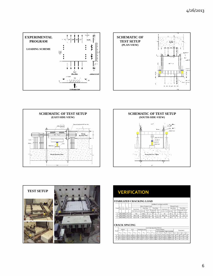
EXPERIMENTAL PROGRAM
LOADING SCHEME
SCHEMATIC OF TEST SETUP
(PLAN-VIEW)
SCHEMATIC OF TEST SETUP (EAST-SIDE-VIEW)
SCHEMATIC OF TEST SETUP (SOUTH-SIDE-VIEW)
TEST SETUP
MC90Error (%)
Proposed Model
Error (%)
MC90Error (%)
Proposed Model
Error (%)
A 200 34000 2.97 -141 756 1166 54 707 -7 92 167 82 103 12B 200 35000 2.79 -107 708 to 744 1078 45 to 52 662 -7 to -11 88 to 105 158 50 to 80 92 5 to -12C 200 33000 2.79 -113 612 to 738 1097 49 to 79 726 19 to -2 86 148 72 97 13
E s , GPa
E c , MPa
f ct , MPa
cs ,
One-WayPanel Two-Way
Flexural Crack
Stabilized Cracking Load (kN)
Experiment (total side jacks)
Direct Tension Crack
Two-WayExperiment
(center Jack)
One-Way
STABILIZED CRACKING LOAD
SII
maxx SII
maxy SII
maxx SII
maxy SII
minx SII
miny SII
maxx SII
maxy
A 677 (57) 374 (-10) 1033 (140) 365 (-12) 503 (39) 503 (64) 217 (-27) 177 (-12) 652 (52) 733 (77) 517 (20) 477 (15) 295 200 430 414B 833 (11) 478 (-12) 1231 (64) 449 (-17) 561 (11) 359 (-11) 212 (-18) 168 (-38) 641 (-15) 724 (34) 512 (-32) 468 (-13) 260 270 750 540C 677 (115) 306 (-13) 1033 (228) 337 (-4) 511 (81) 257 (-21) 237 (-5) 152 (-49) 662 (110) 716 (105) 474 (50) 452 (29) 250 300 315 350
PanelS mx S my S
IIminx S
IIminy
Low Probability High Probability
Crack Spacing (mm) (%Error)MC90 EC2 Rizk&Marzouk Proposed Model
Experiment
S maxx S maxy S maxx S maxy
CRACK SPACING
4/26/2013
7
0
0.1
0.2
0.3
0.4
0.5
0.6
0.7
0.8
0 100 200 300 400 500 600
Cra
ck W
idth
(m
m)
Each Side Jack (kN)
AC
FG
Ab
BbMC90
EC2Proposed
Panel A
0
0.1
0.2
0.3
0.4
0.5
0.6
0.7
0.8
0 100 200 300 400
Cra
ck W
idth
(m
m)
Each Side Jack (kN)
A
C
D
F
G
Ab
MC90
EC2
Proposed
Panel B
0.000.050.100.150.200.250.300.350.400.450.500.55
0 100 200 300 400
Cra
ck W
idth
(m
m)
Each Side Jack (kN)
ADEFGAbMC90EC2Proposed
Panel C
0.00
0.10
0.20
0.30
0.40
0.50
0.60
0 20 40 60 80 100 120 140
Cra
ck W
idth
(m
m)
Center Jack (kN)
E
H
MC90
EC2
Gergely-Lutz
Frosch
ACI 350-06
Nawy
Proposed
Panel A
0.00
0.10
0.20
0.30
0.40
0.50
0 20 40 60 80 100
Cra
ck W
idth
(m
m)
Center Jack (kN)
B
E
MC90
EC2
Gergely-Lutz
Frosch
ACI 350-06
Nawy
Proposed
Panel B
0.00
0.05
0.10
0.15
0.20
0.25
0.30
0 20 40 60 80 100 120
Cra
ck W
idth
(m
m)
Center Jack ()
B
MC90
EC2
Gergely-Lutz
Frosch
ACI350-06
Nawy
Proposed
Panel C
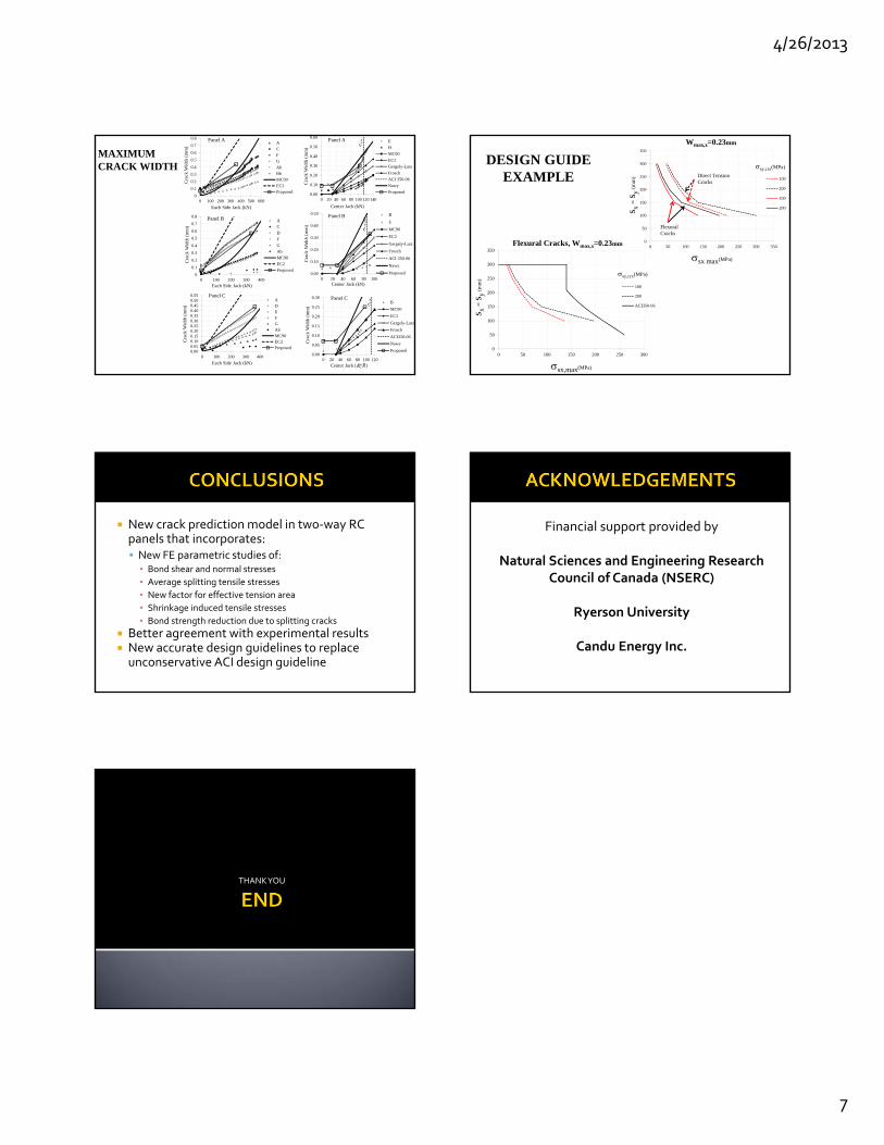
MAXIMUM CRACK WIDTH
0
50
100
150
200
250
300
350
0 50 100 150 200 250 300 350
s x=
s y(m
m)
sx,max(MPa)
Wmax,x=0.23mm
100
200
100
200
sy,crx(MPa)
Flexural Cracks
Direct Tension Cracks
0
50
100
150
200
250
300
350
0 50 100 150 200 250 300
s x=
s y(m
m)
sx,max(MPa)
Flexural Cracks, Wmax,x=0.23mm
100
200
ACI350-06
sy,crx(MPa)
DESIGN GUIDE EXAMPLE
New crack prediction model in two‐way RC panels that incorporates: New FE parametric studies of:▪ Bond shear and normal stresses
▪ Average splitting tensile stresses
▪ New factor for effective tension area
▪ Shrinkage induced tensile stresses
▪ Bond strength reduction due to splitting cracks
Better agreement with experimental results New accurate design guidelines to replace unconservative ACI design guideline
Financial support provided by
Natural Sciences and Engineering Research Council of Canada (NSERC)
Ryerson University
Candu Energy Inc.
THANK YOU


![ACI-350[1].3-06 Seismic Design of Liquid-Containing](https://img.pdfslide.net/doc/110x75/55cf9793550346d033925fad/aci-35013-06-seismic-design-of-liquid-containing.jpg)