Embed Size (px)
Citation preview

Research Article
European Journal of Technique (EJT) Vol 10, Number 2, 2020
Copyright © INESEG ISSN 2536-5010 | e-ISSN 2536-5134 http://dergipark.gov.tr/ejt
EJT
ANALYSIS AND SIMULATION OF A THREE-PHASE DELTA INVERTER FOR A STAR-
CONNECTED RL LOAD
Ahmet GÜNDOĞDU 1*, Reşat ÇELİKEL 2, Şehmus FİDAN 3
In this study, analysis and simulation of the electrical and mathematical
model of a 3-phase and 3-switch delta inverter that fed a three-phase RL
load were performed. First, the Matlab/Simulink model of the inverter was
created. In this model, an RL load of R=10Ω and L=0.005 H was fed and
various simulations were made. The simulation results were obtained using
3 step switching technique for different conduction modes. The delta inverter
that has a simpler structure and less switching elements than conventional
inverter structures can be easily realized with low-cost microcontrollers.
Key words: Power electronics, DC-AC power converters, Pulse inverters,
System analysis and design, Delta inverter.
1. Introduction
As in all areas of science and engineering, there have been also significant developments in the
field of power electronics in the last 50 years. High efficiency and small volume systems consisting of
advanced power electronics circuits have taken the place of low-efficiency, large-volume control
systems that can be carried out in classical terms. Instead of direct current motors used in variable-
speed control systems having high-dynamic-performance, advanced control methods allowing the use
of synchronous, asynchronous and newly developed motor types have been developed [1]. In parallel
with the developments in the material field, new and superior motor types have been added to existing
motor options and smaller and faster switching elements have been developed. Rapid developments
occurring in power electronics switching elements have been effective in the development of power
converters and motor drive systems that provide superior control and operation characteristics.
Power inverters are power supplies that ensuring the control of electrical energy. In all control
systems where advanced control methods are used, a controllable power supply is needed. In variable
1 Department of Electrical and Electronic Engineering, University of Batman, Batman, Turkey, ([email protected])
https://orcid.org/0000-0002-8333-3083 2 Department of Electrical and Electronic Engineering, University of Batman, Batman, Turkey, ([email protected])
https://orcid.org/0000-0002-9169-6466 3 Department of Electrical and Electronic Engineering, ,University of Batman, Batman, Turkey, ([email protected])
https://orcid.org/0000-0002-5249-7245
Received: 2 May 2020; Accepted: 23 August 2020 Doi: https://doi.org/10.36222/ejt.730792
274

European Journal of Technique (EJT) Vol 10, Number 2, 2020
Copyright © INESEG ISSN 2536-5010 | e-ISSN 2536-5134 http://dergipark.gov.tr/ejt
speed applications, the variable voltage and variable frequency required by the motors are provided by
power converters known as controlled power supply.
These converter structures used in drive systems are classified in Fig.1[2]. AC-AC converters
provide conversion from the alternating current to the alternating current that is at different amplitude
and frequency.
Figure 1. Classification of the power converters.
Depending on the type of power transfer link used between them, this conversion is done in two
different ways: i) Single-stage ac-ac conversion (direct link), ii) two-stage ac-dc-ac conversion (dc
link) [3].
High Power
Drives
Direct
Conversion
Indirect Conversion
(dc-link)
Cyclo
Converter
Matrix
Converter
Voltage
source
Current
Source
Load Commutated
Inverter
PWM
Current Source Inverter
2-level Voltage
Source Inverter
Multilevel
Inverter
Single DC
Source
Multiple DC
Source
Active Neutral
Point Clamped
Neutral Point
Clamped
Modular Cascaded
Inverter
Flying
Capacitor
Hybrid Multilevel
Inverter
Cascaded
H-Bridge Inverter
Single Delta
Bridge Cells
Single Star
Bridge Cells
Double Star
Chopper Cells
Double Star
Bridge Cells
Equal DC
Sources
Unequal
DC Sources
NPC+CHB
DC+CHB
Others
275

European Journal of Technique (EJT) Vol 10, Number 2, 2020
Copyright © INESEG ISSN 2536-5010 | e-ISSN 2536-5134 http://dergipark.gov.tr/ejt
Both types of converters require the use of a large number of semiconductor switching
elements and appropriate modulation techniques. In most motor drive systems used in industry, dc link
converters that make two-phase conversion are used. These converters are made up of two parts. First,
by rectifying the ac input voltage with the help of rectifier circuit, it is converted to the dc voltage. In
the second step, with the help of an inverter circuit, this obtained dc voltage is converted to ac voltage
at variable amplitude and frequency. According to the configuration of the used dc link, inverters are
divided into two sections, voltage source inverters (VSI) and current source inverters (CSI).
The voltage source inverters have large filter capacitors that are at the input terminals and hold
the dc link voltage constant. In these inverters, the adjustable output voltage and frequency are
independent of the load current. On the other side, the current source inverters provide a more
controlled load current with the help of large-value inductors connected in series to the input
terminals. That is, the load current is more controlled compared to the voltage. Here, the inverter
output voltage depends on the load impedance. Especially the voltage source inverters are widely used
in academic studies and industrial applications. Delta inverter, which is from the family of voltage
source inverter, was first proposed by Evans and colleagues in 1980 for variable speed drive systems
fed from off-grid insulated batteries [12].
Although there are many studies related to the power converters given in Fig. 1 in the literature,
the studies related to the delta inverter, which cannot take place in this classification, are limited. In
these studies, inverter design and harmonic analysis of it [5,7], vector control application [6], the open-
loop control of the induction motor [4,16], comparison of the delta inverter with the bridge inverter
[8], analysis of the switching techniques having 120° and 240° conduction modes [8], speed and
torque estimation of the BDCM motor [9], vector control and performance analysis of the BACM
motor [10], for large-scale PV systems, a 30 kW grid-connected delta inverter design and analysis of
it [11], self-control application of the BDCM motor with FPGA [13,18], direct torque control of the
induction motor with FPGA [14], direct torque control of the induction motor [12,15,22,23], control of
the delta inverter with SVPWM [17,19,20], and comparison of RFOC and DTC techniques [21] were
performed successfully.
In this study, the electrical and mathematical model of a 3-phase and 3-switch delta inverter that
fed a star-connected RL load was analyzed and simulated in Matlab/Simulink environment. The
simulation results obtained in different conduction modes were presented comparatively.
2. Structure of the Delta Inverter
Inverters are widely used in all areas where variable frequency and voltage are needed [24,25].
Fig. 2 shows the power circuit of the delta inverter, which is a voltage source inverter.
In its structure, there are 3 semiconductor switching elements and 3 insulated equivalent DC
sources. A switching element is connected in series with each DC source to form a leg of the inverter.
The inverter output voltage is generated with the appropriate modulation of S1, S2 and S3 switches.
Each output line voltage is generated by two switching elements.
276

European Journal of Technique (EJT) Vol 10, Number 2, 2020
Copyright © INESEG ISSN 2536-5010 | e-ISSN 2536-5134 http://dergipark.gov.tr/ejt
S3
S2
S1
A
BC
VA
VC VB
VDC
VDC
VDC
+-
+-
+-
Figure 2. Power circuit of delta inverter.
When the switches on each inverter leg enter the conduction and cutoff respectively, positive and
negative alternative voltages emerge at A, B, C points.
In order for the delta inverter to be able to generate a nominal output voltage, only 2 switching
elements must be OFF at any instant of "t" time. If one switching element is OFF and the other two are
in the ON position, the inverter cannot generate the voltage and current required for the load. If all
three switching elements are in OFF position in the same "t" instant, then the inverter is short
circuited. Short-circuit currents at high-value occur and damage the inverter. To avoid short circuit, 3
switching elements must not be in the conduction at the same time.
For the switching elements, the state of being in the conduction is expressed with 1 and the state
of being in cutoff is expressed with 0. Accordingly, SA, SB, SC switching functions can be written as
follows,
𝑆𝐴,𝐵,𝐶 = {1, 𝑆1, 𝑆2, 𝑆3 𝑂𝑁0, 𝑆1, 𝑆2, 𝑆3 𝑂𝐹𝐹
(1)
According to this definition, 23 = 8 different switching states forming the VA, VB, VC voltages
at inverter output is obtained. For each switching state, delta inverter generates 8 different voltage
vectors. Six of these voltage vectors (V1, V2, V3, V4, V5, and V6) are called as “active” voltage vector.
Among these, V1, V3, V5 vectors are called “low-amplitude”, V2, V4, V6 vectors are called “high-
amplitude” voltage vectors. Fig. 3 shows the switching states corresponding to each of the 6 active
voltage vectors generated clockwise at inverter output according to the being in conduction and cutoff
states, respectively.
The V0 vector is obtained in the case of S1=S2=S3=0 where all switching elements are in cutoff
and is called “zero” voltage vector. When the zero voltage vector is applied, the source currents and
the external circuit currents become zero.
277
European Journal of Technique (EJT) Vol 10, Number 2, 2020
Copyright © INESEG ISSN 2536-5010 | e-ISSN 2536-5134 http://dergipark.gov.tr/ejt
A’C B
S3 S2 S1
AVDC VDCVDC
+ + +- - -
VCA VBC VAB
V2 [110]
A’C B
S3 S2 S1
AVDC VDCVDC
+ + +- - -
VCA VBC VAB
V4 [011]
A’C B
S3 S2 S1
AVDC VDCVDC
+ + +- - -
VCA VBC VAB
V6 [101]
A’C B
S3 S2 S1
AVDC VDCVDC
+ + +- - -
VCA VBC VAB
V1 [100]
A’C B
S3 S2 S1
AVDC VDCVDC
+ + +- - -
VCA VBC VAB
V3 [010]
A’C B
S3 S2 S1
AVDC VDCVDC
+ + +- - -
VCA VBC VAB
V5 [001]c)
a) b)
d)
e) f)
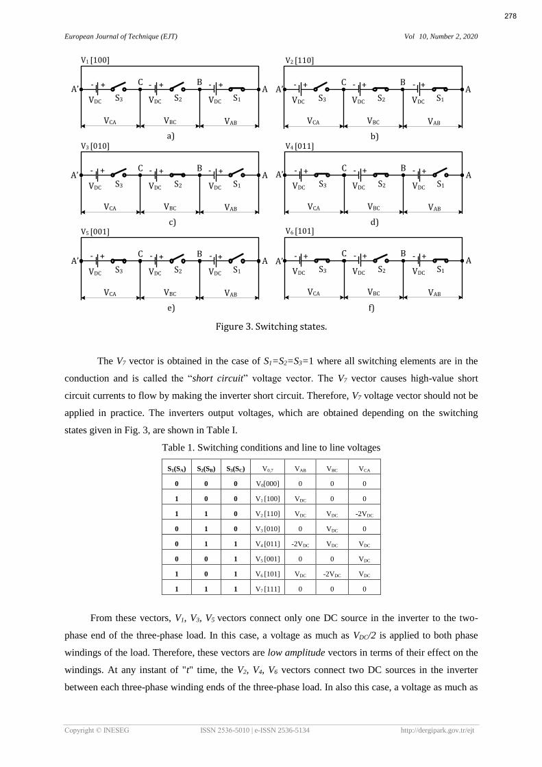
Figure 3. Switching states.
The V7 vector is obtained in the case of S1=S2=S3=1 where all switching elements are in the
conduction and is called the “short circuit” voltage vector. The V7 vector causes high-value short
circuit currents to flow by making the inverter short circuit. Therefore, V7 voltage vector should not be
applied in practice. The inverters output voltages, which are obtained depending on the switching
states given in Fig. 3, are shown in Table I.
Table 1. Switching conditions and line to line voltages
S1(SA) S2(SB) S3(SC) V0,7 VAB VBC VCA
0 0 0 V0[000] 0 0 0
1 0 0 V1 [100] VDC 0 0
1 1 0 V2 [110] VDC VDC -2VDC
0 1 0 V3 [010] 0 VDC 0
0 1 1 V4 [011] -2VDC VDC VDC
0 0 1 V5 [001] 0 0 VDC
1 0 1 V6 [101] VDC -2VDC VDC
1 1 1 V7 [111] 0 0 0
From these vectors, V1, V3, V5 vectors connect only one DC source in the inverter to the two-
phase end of the three-phase load. In this case, a voltage as much as VDC/2 is applied to both phase
windings of the load. Therefore, these vectors are low amplitude vectors in terms of their effect on the
windings. At any instant of "t" time, the V2, V4, V6 vectors connect two DC sources in the inverter
between each three-phase winding ends of the three-phase load. In also this case, a voltage as much as
278

European Journal of Technique (EJT) Vol 10, Number 2, 2020
Copyright © INESEG ISSN 2536-5010 | e-ISSN 2536-5134 http://dergipark.gov.tr/ejt
VDC is applied to both phase windings of the load. These vectors are high-amplitude vectors in terms of
the effect they created on the winding. V0-7 vectors are defined by the Equation 2.
𝑉0,7(𝑆𝐴𝑆𝐵𝑆𝐶) =
{
V1 = V3 = V5, Low amp. vector V2 = V4 = V6, High amp. vector V0, Zero volt. vector
V7, Short Circuit volt. vector
(2)
3. Delta Inverters and Star-Connected Load
In Fig. 4, the connection of a 3-phase star-connected RL load to the delta inverter is presented.
VBn
Z
Z
Z
ia
ib
ic
B
VA
C
A
VC
VDC+-
S1
-+
VDC
S2S3
+
-VDC
RL LOAD
Figure 4. The RL load that is star-connected to the delta inverter.
According to this connection, VAn, VBn, VCn phase-neutral voltages can be written as a result of the SA,
SB, SC switching functions, as in Equations 3-4-5.
𝑉𝐴𝑛 =𝑉𝐷𝐶
2(𝑆𝐴 − 𝑆𝐶) (𝑆𝐵 + 1) (3)
𝑉𝐵𝑛 =𝑉𝐷𝐶
2(𝑆𝐵 − 𝑆𝐴) (𝑆𝐶 + 1) (4)
𝑉𝐶𝑛 =𝑉𝐷𝐶
2(𝑆𝐶 − 𝑆𝐵) (𝑆𝐴 + 1) (5)
The αβ components in the stationary axis frame of phase-neutral voltages are calculated by Equation
6-7.
𝑉𝛼 = 𝑉𝐴𝑛. 𝐶𝑜𝑠 (𝜃) + 𝑉𝐵𝑛. 𝐶𝑜𝑠 (𝜃 + 1200) + 𝑉𝐶𝑛 . 𝐶𝑜𝑠 (𝜃 + 240
0) (6)
𝑉𝛽 = 𝑉𝐴𝑛. 𝑆𝑖𝑛 (𝜃) + 𝑉𝐵𝑛. 𝑆𝑖𝑛 (𝜃 + 1200) + 𝑉𝐶𝑛 . 𝑆𝑖𝑛 (𝜃 + 240
0) (7)
Here, the conversion coefficient matrix obtained by taking 𝜃 = 00 is given in Equation 8. This
coefficient matrix will be used in later motor control applications.
[𝑉𝛼𝑉𝛽] = √
2
3 [1 −1
2⁄−1
2⁄
0 √32⁄ −√3
2⁄] [
𝑉𝐴𝑛𝑉𝐵𝑛𝑉𝐶𝑛
] (8)
279

European Journal of Technique (EJT) Vol 10, Number 2, 2020
Copyright © INESEG ISSN 2536-5010 | e-ISSN 2536-5134 http://dergipark.gov.tr/ejt
VAn, VBn, VCn phase-neutral voltages and Vα, Vβ components of the V1-6 vectors that form these voltages
are given in Table II.
Table II. Switching conditions, phase-neutral voltages and Valpha , Vbeta voltages
S1(SA) S2(SB) S3(SC) V0,7 VAn VBn VCn Vα Vβ 𝑉𝐽=0,7
0 0 0 V0[000] 0 0 0 0 0 0
1 0 0 V1[100]
𝑉𝐷𝐶
2 −
𝑉𝐷𝐶
2 0
3𝑉𝐷𝐶
2√6 −
𝑉𝐷𝐶
2√2
1
√2𝑉𝐷𝐶
1 1 0 V2[110] 𝑉𝐷𝐶 0 −𝑉𝐷𝐶
3𝑉𝐷𝐶
√6
𝑉𝐷𝐶
√2 √2𝑉𝐷𝐶
0 1 0 V3[010] 0
𝑉𝐷𝐶
2 −
𝑉𝐷𝐶
2 0
𝑉𝐷𝐶
√2
1
√2𝑉𝐷𝐶
0 1 1 V4[011] −𝑉𝐷𝐶 𝑉𝐷𝐶 0 −
3𝑉𝐷𝐶
√6
𝑉𝐷𝐶
√2 √2𝑉𝐷𝐶
0 0 1 V5[001] −𝑉𝐷𝐶
2 0
𝑉𝐷𝐶
2 −
3𝑉𝐷𝐶
2√6 −
𝑉𝐷𝐶
2√2
1
√2𝑉𝐷𝐶
1 0 1 V6[101] 0 −𝑉𝐷𝐶 𝑉𝐷𝐶 0 −
2𝑉𝐷𝐶
√2 √2𝑉𝐷𝐶
1 1 1 V7[111] 0 0 0 0 0 0
The regions of the Vα and Vβ components forming the V1-6 vectors and their polarities are given in
Table III.
Table III. Polarities and regions of Valpha , Vbeta components and conduction modes the active
voltage vectors.
⦿
⦿
⦿
⦿
⦿
2400
⦿
1200
V1
V2
V3
V5
V6
V4
α β region
+
+ +
+
+
-
-
- -
-0
0
4
1
2
3
+ β
- β
-
-
1800
-
⦿
⦿
⦿
⦿
⦿
⦿
Conduction Modes
-
-
-
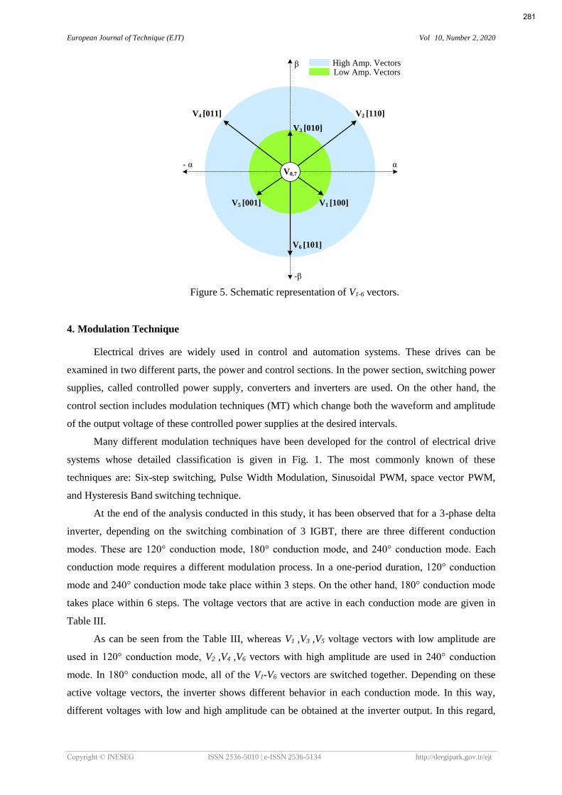
The schematic representation of V1-6 vectors, whose polarities and regions are given in Table III, on
the αβ plane is given in Fig. 5. V1-6 voltage vectors formed by Vα, Vβ voltages in αβ plane are given in
Equation 9 in terms of amplitude. As seen, in terms of amplitude, V2, V4, V6 vectors have two times
more amplitude compared with the V1, V3, V5 vectors.
|𝑉2| = |𝑉4| = |𝑉6| = √2𝑉𝐷𝐶
|𝑉1| = |𝑉3| = |𝑉5| = 1
√2𝑉𝐷𝐶
= 2 (
9)
280
European Journal of Technique (EJT) Vol 10, Number 2, 2020
Copyright © INESEG ISSN 2536-5010 | e-ISSN 2536-5134 http://dergipark.gov.tr/ejt
α
β
V1 [100]
V2 [110]
V3 [010]
V4 [011]
V5 [001]
V6 [101]
V0,7
-β
- α
Low Amp. VectorsHigh Amp. Vectors
Figure 5. Schematic representation of V1-6 vectors.
4. Modulation Technique
Electrical drives are widely used in control and automation systems. These drives can be
examined in two different parts, the power and control sections. In the power section, switching power
supplies, called controlled power supply, converters and inverters are used. On the other hand, the
control section includes modulation techniques (MT) which change both the waveform and amplitude
of the output voltage of these controlled power supplies at the desired intervals.
Many different modulation techniques have been developed for the control of electrical drive
systems whose detailed classification is given in Fig. 1. The most commonly known of these
techniques are: Six-step switching, Pulse Width Modulation, Sinusoidal PWM, space vector PWM,
and Hysteresis Band switching technique.
At the end of the analysis conducted in this study, it has been observed that for a 3-phase delta
inverter, depending on the switching combination of 3 IGBT, there are three different conduction
modes. These are 120° conduction mode, 180° conduction mode, and 240° conduction mode. Each
conduction mode requires a different modulation process. In a one-period duration, 120° conduction
mode and 240° conduction mode take place within 3 steps. On the other hand, 180° conduction mode
takes place within 6 steps. The voltage vectors that are active in each conduction mode are given in
Table III.
As can be seen from the Table III, whereas V1 ,V3 ,V5 voltage vectors with low amplitude are
used in 120° conduction mode, V2 ,V4 ,V6 vectors with high amplitude are used in 240° conduction
mode. In 180° conduction mode, all of the V1-V6 vectors are switched together. Depending on these
active voltage vectors, the inverter shows different behavior in each conduction mode. In this way,
different voltages with low and high amplitude can be obtained at the inverter output. In this regard,
281
European Journal of Technique (EJT) Vol 10, Number 2, 2020
Copyright © INESEG ISSN 2536-5010 | e-ISSN 2536-5134 http://dergipark.gov.tr/ejt
delta inverter can be used in many different applications. Using these three basic conduction modes,
more advanced different modulation algorithms can also be developed.
For the 120°, 180° and 240° conduction modes, switching states, phase-neutral voltages that can
be obtained from the inverter output, and phase-phase voltages are shown in Fig. 6. These graphs are
obtained in the condition in which the load connected to the inverter output is star-connected.
S1
S2
S3
0 1200 2400 3600
100
0
VAn
0
VBn
0VCn
+VDC/2
VAB
VBC
VCA
+VDC
+VDC
+VDC
0
0
0
010 001
-VDC/2+VDC/2
+VDC/2-VDC/2
-VDC/2
1200 Mode
S1
S2
S3
0 1200 2400 3600
100 011 101
0
VAn
0
VBn
0VCn
+VDC
+VDC
-VDC
+VDC
-VDC
-VDC
VAB
VBC
VCA
+VDC
+VDC
-2VDC
-2VDC
-2VDC
+VDC
+VDC
0
0
0
110 010 001
600 1800 3000
1800 Mode
S1
S2
S3
0 1200 2400 3600
1 1 0 0 1 1 1 0 1
0
VAn
0
VBn
0VCn
+VDC
+VDC
-VDC
+VDC
-VDC
-VDC
VAB
VBC
VCA
+VDC
+VDC
-2VDC
-2VDC
-2VDC
+VDC
+VDC
0
0
0
2400 Mode
Figure 6. For 120°, 180° and 240° conduction modes, switching states, phase-neutral voltages
that can be obtained from inverter output, and phase-phase voltages
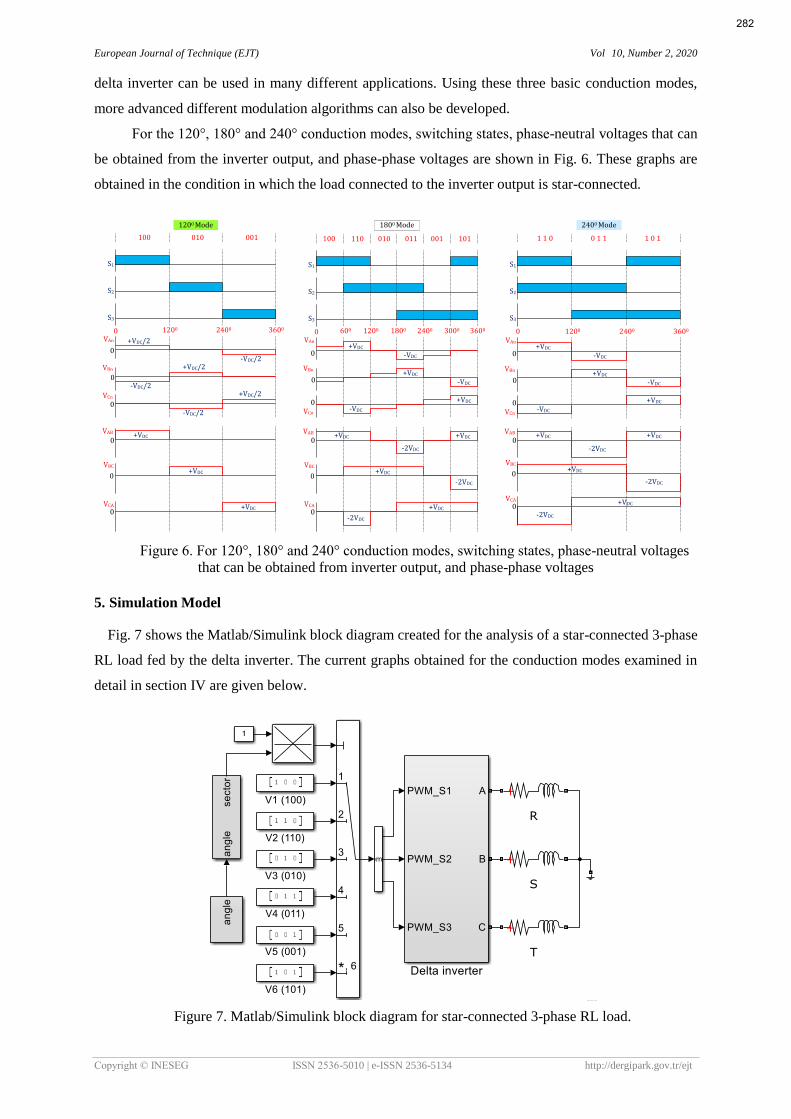
5. Simulation Model
Fig. 7 shows the Matlab/Simulink block diagram created for the analysis of a star-connected 3-phase
RL load fed by the delta inverter. The current graphs obtained for the conduction modes examined in
detail in section IV are given below.
Figure 7. Matlab/Simulink block diagram for star-connected 3-phase RL load.
282

European Journal of Technique (EJT) Vol 10, Number 2, 2020
Copyright © INESEG ISSN 2536-5010 | e-ISSN 2536-5134 http://dergipark.gov.tr/ejt
For modulation, switching elements were switched by selecting 120°, 180° and 240°
conduction modes. Fig. 8 shows the angular change graph of the modulation signal, from which these
conduction modes are obtained, and the sectors. This modulation signal, which was obtained by the
movement of the unit vector with 50 Hz scanning frequency in the 360° circular plane, was divided
into 3 regions of 120-degree within a one-period of time. These regions are called sectors and different
switches are switched sequentially in each sector.
Figure 8. Angular change graph of modulation signal and sectors.
The change of this given modulation signal was carried out and simulations were performed
primarily in 120° conduction mode by using sectors, and the graph for the obtained load current is
given in Fig. 9. In this conduction mode, at any instant of "t" time, only a DC source and a switching
element are on. Because the DC source voltage disperses equally on both phase windings, the phase
currents have I/2 amplitude. Any two of the star-connected 3 phase windings are equal to each other in
terms of amplitude, but they are in opposite directions. Since the third winding is not active, this
winding current is zero.
Figure 9. 3 phase load currents obtained in 120° conduction mode.
The graph of the load current obtained in 240° conduction mode is given in Fig. 10. In this
283

European Journal of Technique (EJT) Vol 10, Number 2, 2020
Copyright © INESEG ISSN 2536-5010 | e-ISSN 2536-5134 http://dergipark.gov.tr/ejt
conduction mode, two switching elements and two DC sources are active at any instant of "t" time.
Because both sources are connected in series, the total end voltage is as much as -2VDC and each
winding voltage is as much as VDC. Winding currents have “I” amplitude. Any two of the 3 phase star-
connected windings are equal to each other in terms of amplitude, but they are in opposite directions.
Since the first and second winding currents flow in reverse direction over the third winding, this
winding current is zero. Fig. 11 shows the graphs belonging to the phase and line voltages obtained in
240° conduction mode. In terms of amplitude, the winding phase voltages are as much as +VDC and -
VDC and line voltages are as much as 𝑉𝐴𝐵 = 𝑉𝐷𝐶, 𝑉𝐵𝐶 = 𝑉𝐷𝐶, 𝑉𝐶𝐴 = −2𝑉𝐷𝐶, respectively.
Figure 10. 3-phase load currents obtained in 240° conduction mode.
Figure 11. Phase and line voltages obtained in 240° conduction mode.
The graphs of the load current obtained in 180° conduction mode are given in Fig. 12. This
conduction mode is obtained by the use of 120° and 240° conduction modes together. Each phase
current is formed by the synthesis of the phase currents with I/2 and I amplitude.
284

European Journal of Technique (EJT) Vol 10, Number 2, 2020
Copyright © INESEG ISSN 2536-5010 | e-ISSN 2536-5134 http://dergipark.gov.tr/ejt
Figure 12. 3-phase load currents obtained in 180° conduction mode.
Moreover, in Fig. 13, the Iha currents obtained from a_phase in each three conduction modes are given
in a single graph.
Figure 13. A phase currents obtained in 120°, 180°, 240° conduction modes.
6. Conclusion
In this study, analysis of the electrical and mathematical model of a three-phase three-switch
delta inverter feeding a three-phase RL load was performed. By feeding an RL load having R=10Ω
285

European Journal of Technique (EJT) Vol 10, Number 2, 2020
Copyright © INESEG ISSN 2536-5010 | e-ISSN 2536-5134 http://dergipark.gov.tr/ejt
and L=0.005 H through the simulation model, various results were obtained. The simulation results
were obtained using three-step switching techniques for different conduction modes of 120°, 180°, and
240°. In all three conduction modes, one of the phase winding currents is zero. This is a problem for
three-phase star-connected loads fed by balanced sinusoidal voltages. In this respect, delta inverter
should be analyzed separately for the loads with different connection group. The delta inverter having
a simpler structure and less switching elements than conventional inverter structures can be easily
realized with low-cost microcontrollers. Conduction and switching losses are low. For three phase and
six phase brushless DC motors and stepper motors fed with more sequential voltages, it has an
appropriate driver characteristic.
References
[1] Miller, E. J., 1989. Brushless Permanent Magnet and Reluctance motor Drivers, Oxford University
Pres, Oxford.
[2] Natarajan, P., Kaliannan, P., 2017. A comprehensive review on reduced switch multilevel inverter
topologies, modulation techniques and applications, Renew. and Sust. Energy Rev.,76, 1248–
1282.
[3] Ozpineci, B., Tolbert, L.M., 1999. Cycloconverters, IEEE, Power Electronics Society Tutorials
Webpage.
[4] Evans, P.D., Dodson, R.C., Eastham, J.F., et al., 1980. Delta inverter, Proceedings. IEE, vol. 127,
No:6, 333-340.
[5] Trzynadlowski, A.M., Ji, S., Legowski, S., 1991. Random pulse width modulation of delta inverter
for automotive applications, Conference Record of the IEEE Industry Applications Society Annual
Meeting, 826-833.
[6] Trzynadlowski, A.M., Legowski, S., 1992. Vector control of delta inverter, Conference Record of
the IEEE Industry Applications Society Annual Meeting, vol.1, 1050-1057.
[7] Evans, P.D., Dodson, R.C., Eastham, J.F., 1984. Sinusoidal Pulsewidth Modulation Strategy for
the Delta Inverter, IEEE Transactions on Industry Applications, vol. IA-20, no.3, 651-655.
[8] Brooks, D.M., Fisher, G.A., Oates, C., et al. 1982. Discussion on ‘delta inverter, IEE Proc. B
Electric Power Applications, 129(2), 177–179.
[9] Rhouma, A.B., Masmoudi, A., 2010. Torque and Speed Estimators to be Implemented in a Control
Strategy Dedicated to TSTPI-Fed BDCM Drives, 2010 7th International Multi-Conference on
Systems, Signals and Devices.
[10] Affene, A., Masmoudi, A., Rhouma, A.B., 2013. Investigation of the Performance of a Vector-
Controlled Delta-Inverter Fed BACM Drive, Eighth International Conference and Exhibition on
Ecological Vehicles and Renewable Energies (EVER), 1-4.
286

European Journal of Technique (EJT) Vol 10, Number 2, 2020
Copyright © INESEG ISSN 2536-5010 | e-ISSN 2536-5134 http://dergipark.gov.tr/ejt
[11] Sandoval, J.J., Ramos.Ruiz, J., Daniel, M., et al. 2014. A new delta inverter system for grid
integration of large scale photovoltaic power plants, IEEE Applied Power Electronics Conf.
Exposition – APEC 2014, 1255–1262.
[12] Ouarda, A., Nouira, I., Badsi, B.E., Masmoudi, A., 2014. DTC Strategies Dedicated to IM Drives
Fed by Reduced- Structure Inverters Emulating the Conventional One: Application to Low-Cost
Automotive Actuators, 2014 17th International Conference on Electrical Machines and Systems
(ICEMS), 169-174.
[13] Alouane, A., Rhouma, A.B., Khedher, A., 2014. FPGA Implementation of a dedicated self-
control strategy for a delta inverter fed BDCM Drive, International conference on science and
electric technology in Magreb (CISTEM), Tunis, 1-8.
[14] Alouane, A., Rhouma, A.B., Kheder, A., 2014. FPGA implementation of a dtc strategy dedicated
to three-switch three-phase inverter-fed induction motor drives, 15th Int. Conf. Sciences and
Techniques of Automatic Control and Computer Eng., 202–208.
[15] Nouira, I., Badsi, B.E., Masmoudi, A., 2015. DTC of three-switch three-phase inverter fed
induction motor drives, Tenth Intern. Conf. on Ecological Vehicles and Renewable Energies
(EVER), 1-8.
[16] Badsi, I.N.E., Badsi, B.E., Masmoudi, A., 2016. Space vector PWM techniques for B3-VSI fed
three-phase IM drives, IEEE Vehicle Power and Propulsion Conf., 1-6.
[17] Mahdhi, H., Rhouma, A.B., Hamouda, M., 2016. A New Space Vector Modulation Strategy for
Three- Switch Three-Phase Delta Inverter, 7th Int. Conf. on Sciences of Electronics,
Technologies of Information and Telecommunications, 455-460.
[18] Alouane, A., Rhouma, A.B., Khedher, A., 2016. A self-control strategy for a delta inverter fed
BDCM Drive using Xilinx system generator with fixed point/floating point mode, 17th int. conf.
on Sciences and Techniques of Automatic control & computer engineering-STA'2016, 468-474.
[19] Alouane, A., Rhouma, A.B., Hamouda, M., Khedher, A., 2018. Efficient FPGA-based real-time
Implementation of an SVPWM Algorithm for a Delta Inverter, IET Power Electronics, Vol:
11 , No: 9, 1611–1619.
[20] Badsi, I.N.E., Badsi, B.E., Masmoudi, A., 2018. Carrier-Based and Space Vector PWM
Techniques for Delta Inverter Fed IM Drive Operating in Linear and Overmodulation Ranges,
15th Int. Multi-Conf. on Systems, Signals & Devices, 1323-1328.
[21] Badsi, I.N.E., Badsi, B.E., Masmoudi, A., 2018. RFOC and DTC Strategies for Reduced
Structure B3-Inverter Fed Induction Motor Drives, 15th International Multi-Conference on
Systems, Signals & Devices, 1317-1322.
[22] Badsi, B.E., 2013. Six-Switch Inverter Emulation Based DTC Strategy Dedicated to Three-
Switch Inverter-Fed Induction Motor Drives, Computation and Mathematics in Electrical and
Electronic Engineering, vol. 32, no. 1, 289-301.
[23] Badsi, I.N.E., Badsi, B.E., Masmoudi, A., 2018. DTC strategies for three-switch three-phase
inverter-fed induction motor drives, COMPEL-The international journal for computation and
mathematics in electrical and electronic engineering 37:6, 2176-2194.
287

European Journal of Technique (EJT) Vol 10, Number 2, 2020
Copyright © INESEG ISSN 2536-5010 | e-ISSN 2536-5134 http://dergipark.gov.tr/ejt
[24] İnci, M., 2019. Performance Analysis of T-type Inverter Based on Improved Hysteresis Current
Controller, Balkan Journal of Electrical & Computer Engineering, vol. 7, no. 2, 149-155.
[25] Asker, M.E., Kılıc, H., 2017. Modulation Index And Switching Frequency Effect On Symmetric
Regular Sampled SPWM, European Journal of Technic, vol. 7, no. 2, 102-109.
288