Embed Size (px)
Citation preview
ARTICLE
Analysis and strengthening of caisson foundations foruplift loadsSerhan Guner and Jean Carrière
Abstract: Many existing self-supporting towers are built with constant-width caisson foundations. Due to the increased demandto add more antennas to the towers, and more stringent strength requirements in recently revised design standards, manyexisting caisson foundations require significant strengthening for additional uplift resistance. Although a number of retrofitdesign solutions are frequently used in practice, there is a lack of literature providing guidelines for the proper analysis ofretrofitted foundations. This study proposes a detailed analysis and design methodology to significantly increase the upliftcapacity of existing caissons through the use of helical micro piles and reinforced concrete cap beams. Strut-and-tie models aredeveloped and nonlinear finite element analyses are undertaken to verify the behaviour of the proposed design. The overalldesign methodology is presented in a case study involving an existing tower. The proposed design has a general applicability andis suitable for applications where there is limited space around the existing foundations.
Key words: caisson foundations, deep beams, finite elements, micro piles, modeling, nonlinear analysis, retrofit, strut-and-tiemethod, towers, uplift loads.
Résumé : Un grand nombre de tours autoportantes existantes sont construites avec des fondations sur puits bétonnés de largeurconstante. En raison de la demande accrue pour ajouter plus d'antennes aux tours et des exigences de résistance plus rigoureusessuite a la récente révision des normes de conception, un grand nombre de fondations sur puits bétonnés existantes requièrentune importante consolidation en vue d'augmenter la résistance au soulèvement. Bien qu'on utilise fréquemment un certainnombre de solutions de conception adapté, il y peu de littérature qui donne des directives pour bien analyser les fondationsadaptées. Cette étude propose une analyse détaillée et une méthodologie de conception en vue de considérablement augmenterla capacité de résistance au soulèvement des puits bétonnés au moyen de micropieux hélicoïdes et de poutres a tête en bétonarmé. On développe des modèles a treillis et on fait des analyses par éléments finis non linéaires afin de vérifier le comportementde la conception proposée. On présente la méthodologie de conception générale au moyen d'une étude de cas impliquant unetour existante. La conception proposée a une applicabilité générale et convient dans le cas d'applications où il y a un espacerestreint autour des fondations existantes. [Traduit par la Rédaction]
Mots-clés : fondations sur puits bétonnés, poutres-cloisons, micropieux, modélisation, analyse non linéaire, adapté, méthode atreillis, tours, charge de soulèvement.
IntroductionNew wireless technologies, such as LTE and 4G networks, have
created an increased demand for new telecommunication instal-lation in the last decade. Due to high costs of installing new tow-ers and of purchasing land (especially in and around urban areas),it has become more attractive for service providers to co-locate onexisting towers; however, many of these towers are at their designcapacity. As a consequence, many existing towers require strength-ening through reinforcements to support the increased loads. Thedesign of these reinforcements must satisfy the latest version of theCSA S37 standard, which is generally more stringent in strengthrequirements than the previous editions of the standard. One criticalchange to this standard has been a reduction in the resistance factorvalue for caisson foundations that are subjected to uplift loads (seeTable 1). A caisson foundation designed at capacity prior to 2001would be overloaded by a factor of 2.0 according to the 2001 editionof the standard, and by a factor of 1.5 according to the current 2013edition of the standard. The latest standard has required significant
strengthening of many existing caisson foundations, especiallythose designed prior to 2001.
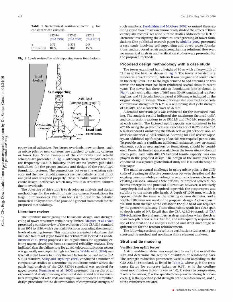
Caisson foundations are commonly used for self-supportingtowers. These towers are subjected to significant overturning mo-ments, and small axial forces. The overturning moments are resistedby the tensile and compressive resistance of the caisson foundations,as illustrated in Fig. 1. Due to the changing nature of wind directionand pressure, caisson foundations are exposed to cyclic load rever-sals. Compared to other foundation systems carrying a constant levelof axial compression, caisson foundations are subjected to a morecomplex state of stress. Caissons typically resist the applied compres-sion through skin friction and tip bearing, while the tensile resis-tance is provided only by skin friction and self-weight of the caisson.Consequently, strengthening of an existing caisson presents sig-nificant challenges to increase the uplift capacity by a factor inexcess of 1.5.
A number of schemes are commonly employed in industry toincrease the uplift capacities of existing caissons. Weight blocks,such as thick concrete slabs, are attached to existing caissons forsmall overloads, using discontinuous dowel bars developed with
Received 10 August 2015. Accepted 14 February 2016.
S. Guner. Department of Civil Engineering, University of Toledo, Toledo, OH 43606, USA.J. Carrière. Morrison Hershfield Limited, Toronto, ON L3T 7W4, Canada.Corresponding author: Serhan Guner (email: [email protected]).Copyright remains with the author(s) or their institution(s). Permission for reuse (free in most cases) can be obtained from RightsLink.
411
Can. J. Civ. Eng. 43: 411–419 (2016) dx.doi.org/10.1139/cjce-2015-0350 Published at www.nrcresearchpress.com/cjce on 15 April 2016.
Can
. J. C
iv. E
ng. D
ownl
oade
d fr
om w
ww
.nrc
rese
arch
pres
s.co
m b
y D
r. S
erha
n G
uner
on
04/2
4/16
For
pers
onal
use
onl
y.
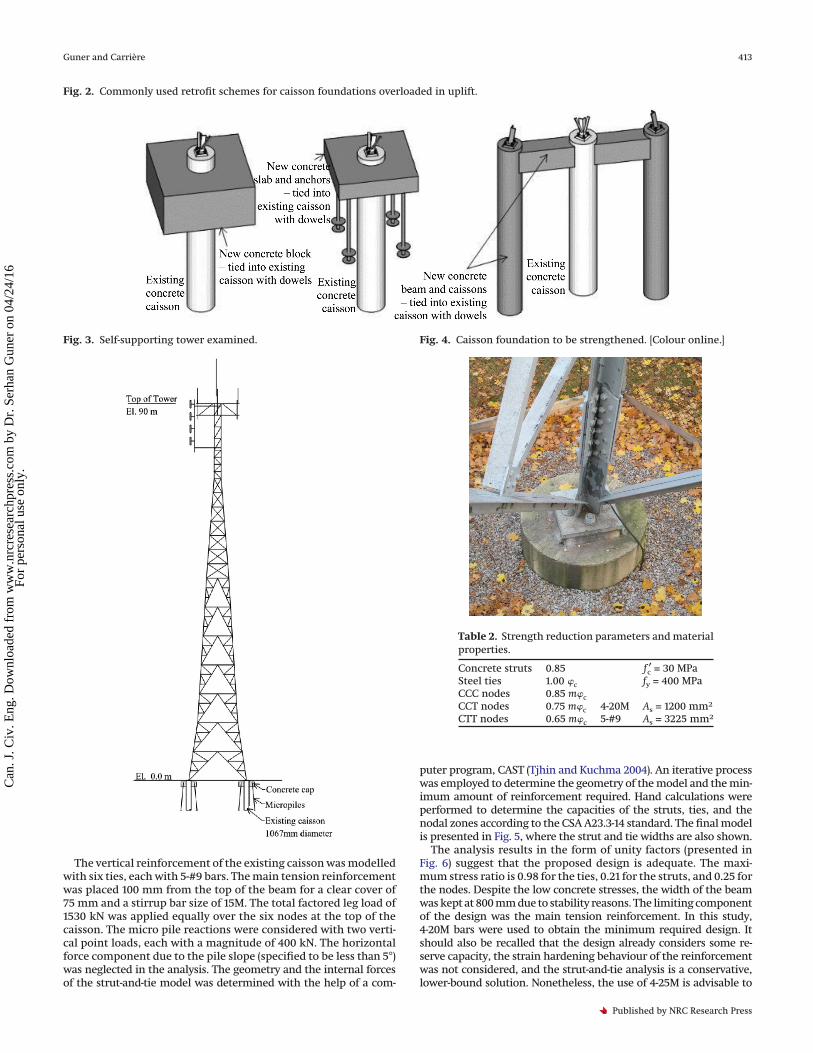
epoxy-based adhesives. For larger overloads, new anchors, suchas micro piles or new caissons, are attached to existing caissonsor tower legs. Some examples of the commonly used retrofitschemes are presented in Fig. 2. Although these retrofit schemesare frequently used in industry, there are no known publishedguidelines for the proper analysis and design of the retrofittedfoundation systems. The connections between the existing cais-sons and the new retrofit elements are particularly critical. If notanalyzed and designed properly, these retrofits could render anentire design ineffective, which may result in structural failuresdue to overloads.
The objective of this study is to develop an analysis and designmethodology for the retrofit of existing caisson foundations forlarge uplift overloads. The main focus is to present the detailednumerical analysis studies to provide a general framework for theproposed methodology.
Literature reviewThe literature investigating the behaviour, design, and strength-
ening of tower structures remain very limited. Magued et al. (1989)presented a concise review of the evolution of the CSA S37 standardfrom 1954 to 1986, with a particular focus on upgrading the strengthlevels of existing towers. This study also presented a database thatincluded failures of guyed towers taller than 75 m located in Canada.Bruneau et al. (1989) proposed a set of guidelines for upgrading ex-isting towers, developed from a structural reliability analysis. Theyindicated that the failure rate for guyed telecommunication towerswas generally unacceptably high in Canada. Wahba et al. (1994) ana-lyzed 41 guyed towers to justify the load factors to be used in the CSAS37-94 standard. Selby and Dryburgh (1996) conducted a number ofcomparative studies to determine the conditions under which thepatch load analysis of the CSA S37-94 standard was required forguyed towers. Kumalasari et al. (2006) presented the results of anexperimental study involving seven solid steel round bracing mem-bers strengthened with rods and angles, and proposed a simplifieddesign procedure for the determination of compressive strength of
such members. Faridafshin and McClure (2008) examined three ex-isting guyed tower masts and numerically studied the effects of threeearthquake records. Yet none of these studies addressed the lack ofliterature investigating the structural strengthening of tower foun-dations. One published research paper by Abdalla (2002) presenteda case study involving self-supporting and guyed tower founda-tions, and proposed repair and strengthening solutions. However,no numerical analysis and verification studies were presented forthe proposed methods.
Proposed design methodology with a case studyThe tower examined has a height of 90 m with a face-width of
12.2 m at the base, as shown in Fig. 3. The tower is located in aresidential area of Toronto, Ontario. It was designed and constructedin the early 1970s. Due to the high demand to add antennas on thistower, the tower mast has been reinforced several times in recentyears. The tower has three caisson foundations (one is shown inFig. 4), each with a diameter of 1067 mm, 30-#9 longitudinal reinforc-ing bars, and #3 circular hoops spaced at 300 mm, as indicated on theoriginal design drawings. These drawings also specified a concretecompressive strength of 27.6 MPa, a reinforcing steel yield strengthof 414 MPa, and a concrete cover of 76 mm.
A detailed tower analysis was conducted for the increased load-ing. The analysis results indicated the maximum factored upliftand compression reactions to be 1530 kN and 1740 kN, respectively,at each caisson. The factored uplift capacity was calculated to be675 kN using the geotechnical resistance factor of 0.375 in the CSAS37-01 standard. Considering the 136 kN self-weight of the caisson, anoverload factor of 2.1 was obtained. Allowing for a 6% reserve capac-ity, an additional uplift capacity of 800 kN was required per caisson.To provide such a significant additional resistance, new structuralelements, such as new anchors or foundations, should be consid-ered. Due to the limited space available on the tower site, two helicalmicro piles, each with 400 kN factored tensile capacity, was em-ployed in the proposed design. The design of the micro piles wasconducted in a separate geotechnical study and is out of the scope ofthis paper.
The main structural challenge in using micro piles is the diffi-culty of creating an effective connection between the piles and theexisting caissons while providing the required clearance from theexisting caissons. Among a few options, reinforced concrete capbeams emerge as one practical alternative; however, a relativelylarge depth and width is required to provide the proper space andstability to the micro pile heads. A depth of 1000 mm, which isapproximately the same as the existing caisson diameter, and awidth of 800 mm was used in the proposed design. A clear span of700 mm from the face of the caisson to the pile head was requiredby the geotechnical study. These dimensions result in a clear spanto depth ratio of 0.7. Recall that the CSA A23.3-14 standard (CSA2014) classifies flexural members as deep members when the clearspan to depth ratios is less than 2.0, and subsequently requires theuse of the strut-and-tie analysis method and strict anchorage re-quirements for the tension reinforcement.
The following sections present the verification studies using thestrut-and-tie method and nonlinear finite element analyses.
Strut and tie modeling
Verification uplift forcesA strut-and-tie analysis was employed to verify the overall de-
sign and determine the required quantities of reinforcing bars.The strength reduction parameters were taken according to theCSA A23.3-14 standard, as listed in Table 2, where �c is the resis-tance factor for concrete (taken as 0.65), m is the confine-ment modification factor (taken as 1.0), C refers to compression,T refers to tension, fc
′ is the specified compressive strength of con-crete, fy is the specified yield strength of the reinforcement, and Asis the reinforcement area.
Table 1. Geotechnical resistance factor, �, forconstant-width caissons.
S37-94(CSA 1994)
S37-01(CSA 2001)
S37-13(CSA 2013)
� 0.75 0.375 0.5Utilization 100% 200% 150%
Fig. 1. Loads resisted by self-supporting tower foundations.
412 Can. J. Civ. Eng. Vol. 43, 2016
Published by NRC Research Press
Can
. J. C
iv. E
ng. D
ownl
oade
d fr
om w
ww
.nrc
rese
arch
pres
s.co
m b
y D
r. S
erha
n G
uner
on
04/2
4/16
For
pers
onal
use
onl
y.
The vertical reinforcement of the existing caisson was modelledwith six ties, each with 5-#9 bars. The main tension reinforcementwas placed 100 mm from the top of the beam for a clear cover of75 mm and a stirrup bar size of 15M. The total factored leg load of1530 kN was applied equally over the six nodes at the top of thecaisson. The micro pile reactions were considered with two verti-cal point loads, each with a magnitude of 400 kN. The horizontalforce component due to the pile slope (specified to be less than 5°)was neglected in the analysis. The geometry and the internal forcesof the strut-and-tie model was determined with the help of a com-
puter program, CAST (Tjhin and Kuchma 2004). An iterative processwas employed to determine the geometry of the model and the min-imum amount of reinforcement required. Hand calculations wereperformed to determine the capacities of the struts, ties, and thenodal zones according to the CSA A23.3-14 standard. The final modelis presented in Fig. 5, where the strut and tie widths are also shown.
The analysis results in the form of unity factors (presented inFig. 6) suggest that the proposed design is adequate. The maxi-mum stress ratio is 0.98 for the ties, 0.21 for the struts, and 0.25 forthe nodes. Despite the low concrete stresses, the width of the beamwas kept at 800 mm due to stability reasons. The limiting componentof the design was the main tension reinforcement. In this study,4-20M bars were used to obtain the minimum required design. Itshould also be recalled that the design already considers some re-serve capacity, the strain hardening behaviour of the reinforcementwas not considered, and the strut-and-tie analysis is a conservative,lower-bound solution. Nonetheless, the use of 4-25M is advisable to
Fig. 2. Commonly used retrofit schemes for caisson foundations overloaded in uplift.
Fig. 3. Self-supporting tower examined. Fig. 4. Caisson foundation to be strengthened. [Colour online.]
Table 2. Strength reduction parameters and materialproperties.
Concrete struts 0.85 fc′ = 30 MPa
Steel ties 1.00 �c fy = 400 MPaCCC nodes 0.85 m�cCCT nodes 0.75 m�c 4-20M As = 1200 mm2
CTT nodes 0.65 m�c 5-#9 As = 3225 mm2
Guner and Carrière 413
Published by NRC Research Press
Can
. J. C
iv. E
ng. D
ownl
oade
d fr
om w
ww
.nrc
rese
arch
pres
s.co
m b
y D
r. S
erha
n G
uner
on
04/2
4/16
For
pers
onal
use
onl
y.
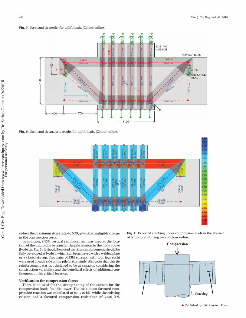
reduce the maximum stress ratio to 0.59, given the negligible changein the construction costs.
In addition, 8-15M vertical reinforcement was used at the loca-tion of the micro pile to transfer the pile tension to the node above(Node 1 in Fig. 5). It should be noted that this reinforcement should befully developed at Node 1, which can be achieved with a welded plateor a closed stirrup. Two pairs of 15M stirrups (with four legs each)were used at each side of the pile in this study. Also note that this tiereinforcement was not designed to be at capacity, considering theconstruction variability and the beneficial effects of additional con-finement at this critical location.
Verification for compression forcesThere is no need for the strengthening of the caisson for the
compression loads for this tower. The maximum factored com-pression reaction was calculated to be 1740 kN, while the existingcaisson had a factored compression resistance of 2550 kN.
Fig. 5. Strut-and-tie model for uplift loads. [Colour online.]
Fig. 6. Strut-and-tie analysis results for uplift loads. [Colour online.]
Fig. 7. Expected cracking under compression loads in the absenceof bottom reinforcing bars. [Colour online.]
414 Can. J. Civ. Eng. Vol. 43, 2016
Published by NRC Research Press
Can
. J. C
iv. E
ng. D
ownl
oade
d fr
om w
ww
.nrc
rese
arch
pres
s.co
m b
y D
r. S
erha
n G
uner
on
04/2
4/16
For
pers
onal
use
onl
y.
However, due to the load sharing, the micro piles will carry a part ofthe total applied compression load and the cap beams will besubjected to positive bending. If no reinforcement is provided atthe bottom of the beams, the system will develop a moment re-lease under compression. This will result in cracking at the lowersegment of the interface, as shown in Fig. 7. For durability rea-sons, the positive bending reinforcement is provided in this study.For this purpose, the micro piles were designed to have a mini-mum compressive load capacity of 400 kN, and another strut-and-tie model was developed with two micro pile reactions and thetotal leg compression applied to the existing caisson. The analysisresults indicated that 4-20M bars were sufficient at the bottom ofthe beams with a stress ratio of 0.98. Once again, it is advisableto use 4-25M, given the negligible change in the constructioncosts.
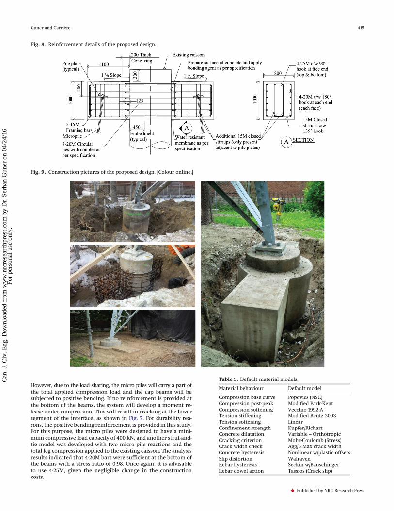
Fig. 8. Reinforcement details of the proposed design.
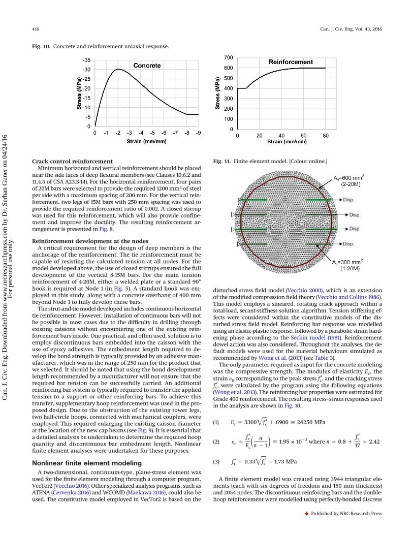
Fig. 9. Construction pictures of the proposed design. [Colour online.]
Table 3. Default material models.
Material behaviour Default model
Compression base curve Popovics (NSC)Compression post-peak Modified Park-KentCompression softening Vecchio 1992-ATension stiffening Modified Bentz 2003Tension softening LinearConfinement strength Kupfer/RichartConcrete dilatation Variable – OrthotropicCracking criterion Mohr-Coulomb (Stress)Crack width check Agg/5 Max crack widthConcrete hysteresis Nonlinear w/plastic offsetsSlip distortion WalravenRebar hysteresis Seckin w/BauschingerRebar dowel action Tassios (Crack slip)
Guner and Carrière 415
Published by NRC Research Press
Can
. J. C
iv. E
ng. D
ownl
oade
d fr
om w
ww
.nrc
rese
arch
pres
s.co
m b
y D
r. S
erha
n G
uner
on
04/2
4/16
For
pers
onal
use
onl
y.
Crack control reinforcementMinimum horizontal and vertical reinforcement should be placed
near the side faces of deep flexural members (see Clauses 10.6.2 and11.4.5 of CSA A23.3-14). For the horizontal reinforcement, four pairsof 20M bars were selected to provide the required 1200 mm2 of steelper side with a maximum spacing of 200 mm. For the vertical rein-forcement, two legs of 15M bars with 250 mm spacing was used toprovide the required reinforcement ratio of 0.002. A closed stirrupwas used for this reinforcement, which will also provide confine-ment and improve the ductility. The resulting reinforcement ar-rangement is presented in Fig. 8.
Reinforcement development at the nodesA critical requirement for the design of deep members is the
anchorage of the reinforcement. The tie reinforcement must becapable of resisting the calculated tension at all nodes. For themodel developed above, the use of closed stirrups ensured the fulldevelopment of the vertical 8-15M bars. For the main tensionreinforcement of 4-20M, either a welded plate or a standard 90°hook is required at Node 1 (in Fig. 5). A standard hook was em-ployed in this study, along with a concrete overhang of 400 mmbeyond Node 1 to fully develop these bars.
The strut-and-tie model developed includes continuous horizontaltie reinforcement. However, installation of continuous bars will notbe possible in most cases due to the difficulty in drilling throughexisting caissons without encountering one of the existing rein-forcement bars inside. One practical, and often used, solution is toemploy discontinuous bars embedded into the caisson with theuse of epoxy adhesives. The embedment length required to de-velop the bond strength is typically provided by an adhesive man-ufacturer, which was in the range of 250 mm for the product thatwe selected. It should be noted that using the bond developmentlength recommended by a manufacturer will not ensure that therequired bar tension can be successfully carried. An additionalreinforcing bar system is typically required to transfer the appliedtension to a support or other reinforcing bars. To achieve thistransfer, supplementary hoop reinforcement was used in the pro-posed design. Due to the obstruction of the existing tower legs,two half-circle hoops, connected with mechanical couplers, wereemployed. This required enlarging the existing caisson diameterat the location of the new cap beams (see Fig. 9). It is essential thata detailed analysis be undertaken to determine the required hoopquantity and discontinuous bar embedment length. Nonlinearfinite element analyses were undertaken for these purposes.
Nonlinear finite element modelingA two-dimensional, continuum-type, plane-stress element was
used for the finite element modeling through a computer program,VecTor2 (Vecchio 2016). Other specialized analysis programs, such asATENA (Cervenka 2016) and WCOMD (Maekawa 2016), could also beused. The constitutive model employed in VecTor2 is based on the
disturbed stress field model (Vecchio 2000), which is an extensionof the modified compression field theory (Vecchio and Collins 1986).This model employs a smeared, rotating crack approach within atotal-load, secant-stiffness solution algorithm. Tension stiffening ef-fects were considered within the constitutive models of the dis-turbed stress field model. Reinforcing bar response was modelledusing an elastic-plastic response, followed by a parabolic strain hard-ening phase according to the Seckin model (1981). Reinforcementdowel action was also considered. Throughout the analyses, the de-fault models were used for the material behaviours simulated asrecommended by Wong et al. (2013) (see Table 3).
The only parameter required as input for the concrete modelingwas the compressive strength. The modulus of elasticity Ec, thestrain �0 corresponding to the peak stress fc
′, and the cracking stressft′, were calculated by the program using the following equations
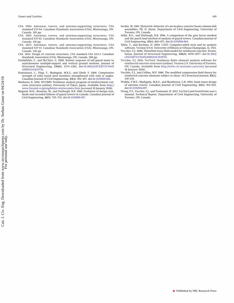
(Wong et al. 2013). The reinforcing bar properties were estimated forGrade 400 reinforcement. The resulting stress–strain responses usedin the analysis are shown in Fig. 10.
(1) Ec � 3300�fc′ � 6900 � 24250 MPa
(2) �0 �fc
′
Ec� nn � 1� � 1.95 × 10�3 where n � 0.8 �
fc′
17� 2.42
(3) ft′ � 0.33�fc
′ � 1.73 MPa
A finite element model was created using 3944 triangular ele-ments (each with six degrees of freedom and 150 mm thickness)and 2054 nodes. The discontinuous reinforcing bars and the double-hoop reinforcement were modelled using perfectly-bonded discrete
Fig. 10. Concrete and reinforcement uniaxial response.
Fig. 11. Finite element model. [Colour online.]
416 Can. J. Civ. Eng. Vol. 43, 2016
Published by NRC Research Press
Can
. J. C
iv. E
ng. D
ownl
oade
d fr
om w
ww
.nrc
rese
arch
pres
s.co
m b
y D
r. S
erha
n G
uner
on
04/2
4/16
For
pers
onal
use
onl
y.

truss elements (each with two degrees of freedom at each node). Themodel was restrained with four hinges on one side, and the loadingwas applied uniformly on the other side with 0.1 mm displacementincrements. A displacement-controlled analysis was employed to ob-tain the post-peak response, ductility, and failure mode. The finiteelement mesh is presented in Fig. 11.
To determine the required embedment length for the discontinu-ous bars, six different models were created by varying the embed-ment lengths: 650, 550, 450, 350, 250, and 170 mm for Models 1 to 6,respectively. The load–displacement responses and the failureloads for all six models are presented in Fig. 12. The responses ofModels 1 to 5 exhibited similar behaviours: an initial peak load,followed by a sudden drop due to major cracking at the termina-tion of the reinforcement, and a stiffening response due to theactivation of the supplementary hoop reinforcement.
Analysis results indicated that the required minimum failureload of 400 kN was achieved with an embedment length of450 mm (Model 3). This model exhibited a ductile response gov-erned by the yielding of the supplementary hoop reinforcement(see Fig. 13). The three stages of cracking are presented inFig. 14.
The change in the embedment length affected the load capacityand the failure mode of the caisson significantly. The crack pat-terns for all models at failure are presented in Fig. 15. An embed-ment length of 250 mm, which is recommended by the adhesivemanufacturer, resulted in an undesirable failure mode involvingthe local failure of concrete (see Fig. 15, Model 5). The hoop steelwas partially effective, and increased the load capacity by only 11%beyond the first peak load (as compared to 55% in Model 1). Thefailure load obtained was 250 kN, which is significantly lowerthan the required value of 400 kN. An embedment length of170 mm, which is less than the length recommended by the adhe-sive manufacturer, resulted in a brittle failure upon first crackingat an applied load of 200 kN. This failure was the result of disin-tegration of the concrete at the edge (see Fig. 15, Model 6). Thehoops were ineffective in this model and did not provide any in-crease in the load capacity. Note that the analysis uses perfectlybonded bars; a possible bond slip may accompany this failure, mak-ing it even more undesirable.
Summary and conclusionsMany existing self-supporting towers rely on caisson founda-
tions for uplift resistance. Increased demand for cellular antennatowers and public opposition to new towers in urban centres, havedriven the addition of antennas on existing towers. This increasein loads and more stringent strength requirements in recent updatesto design standards have required strengthening of many existingcaisson foundations. Although a number of retrofit schemes arecommonly used in practice, there is a lack of published guidelines forthe proper analysis and design of the retrofitted foundation systems.In this study, an analysis and design methodology was presented for
the strengthening of reinforced concrete caisson foundations forlarge uplift loads. Strut-and-tie models were developed to verify theoverall strength and integrity. Nonlinear finite element analyseswere undertaken to assess the performance and the failure mode atthe micro level. The proposed methodology was introduced with acase study involving an existing self-supporting tower. The devel-oped design drawings and construction pictures were also presented.The results of the studies conducted support the following conclu-sions:
1. The addition of new structural elements is required to sig-nificantly increase the uplift capacity of existing caissonfoundations.
2. The capacity and behaviour of the retrofitted foundation mustbe verified by a numerical analysis. The analysis must demon-strate that the connections between the new elements andexisting foundations are adequate to transfer the load.
Fig. 12. Load and deflection results for different embedment lengths. [Colour online.]
Fig. 13. Reinforcing bar stresses for Model 3 (in MPa). [Colouronline.]
Guner and Carrière 417
Published by NRC Research Press
Can
. J. C
iv. E
ng. D
ownl
oade
d fr
om w
ww
.nrc
rese
arch
pres
s.co
m b
y D
r. S
erha
n G
uner
on
04/2
4/16
For
pers
onal
use
onl
y.

3. A proper analysis method must be employed for deep beamsusing the strut-and-tie methods and nonlinear finite ele-ment analyses. Simple sectional analysis methods withsimply-supported slender beam approaches are not validfor deep beams.
4. Special attention must be paid to the reinforcement develop-ment for deep members, including simple support points. Anoverhang beyond the support points is required to develop thereinforcing bars. T-headed bars or welded plates may also beemployed if there is limited space for such a beam overhang.
5. Providing the recommended bond development length for ep-oxy anchored bars does not ensure that the bar tension can safelybe carried. The designer must ensure that there are adjacentrebars available (or designed) to transfer the tension load of theterminated bars to a support point or other reinforcing bars.
6. Proper crack control reinforcement must be provided to ensurethe long-term durability of deep beams. This typically requiresusing an orthogonal grid of reinforcing bars near each face ofdeep beams.
7. The analysis and design process must be repeated for all pos-sible load cases. Even though the new elements are designedfor uplift loads, they may be subjected to significant compres-sion loads due to load sharing.
8. The analysis and design methodology proposed in this studywas numerically shown to increase the uplift capacity of an
existing caisson by a factor of 2.1. Overall behaviour, ductility,and the failure mode of the retrofitted system were found tobe satisfactory.
9. The proposed design has a general applicability and is suitablefor applications where there is limited space around the exist-ing caissons.
AcknowledgementsThe authors would like to thank Mr. Zane Biblow for his contri-
butions to an earlier version of the design proposed in this study.The authors would also like to acknowledge the contribution ofSálvio Aragão Almeida Júnior, an undergraduate summer studentfunded by the Science Without Borders Scholarship Program, forassisting in the finite element analyses presented in this paper.
ReferencesAbdalla, H.A. 2002. Assessment of damages and repair of antenna tower con-
crete foundations. Construction and Building Materials, 16(8): 527–534. doi:10.1016/S0950-0618(02)00028-4.
Bruneau, M., Magued, M.H., and Dryburgh, R.B. 1989. Recommended guidelinesfor upgrading existing towers. Canadian Journal of Civil Engineering, 16(5):733–742. doi:10.1139/l89-108.
Cervenka, V. 2016. ATENA: Software for nonlinear analysis of reinforced con-crete structures [online]. Prague, Czech Republic. Available from http://www.cervenka.cz [accessed 18 January 2016].
Fig. 14. Crack patterns for Model 3: (a) at the first peak, (b) at the load drop, and (c) at failure. [Colour online.]
Fig. 15. Crack patterns at failure for different embedment lengths. [Colour online.]
418 Can. J. Civ. Eng. Vol. 43, 2016
Published by NRC Research Press
Can
. J. C
iv. E
ng. D
ownl
oade
d fr
om w
ww
.nrc
rese
arch
pres
s.co
m b
y D
r. S
erha
n G
uner
on
04/2
4/16
For
pers
onal
use
onl
y.
CSA. 1994. Antennas, towers, and antenna-supporting structures. CSAstandard S37-94. Canadian Standards Association (CSA). Mississauga, ON,Canada. 105 pp.
CSA. 2001. Antennas, towers, and antenna-supporting structures. CSAstandard S37-01. Canadian Standards Association (CSA). Mississauga, ON,Canada. 118 pp.
CSA. 2013. Antennas, towers, and antenna-supporting structures. CSAstandard S37-13. Canadian Standards Association (CSA). Mississauga, ON,Canada. 216 pp.
CSA. 2014. Design of concrete structures. CSA standard CSA A23.3. CanadianStandards Association (CSA). Mississauga, ON, Canada. 290 pp.
Faridafshin, F., and McClure, G. 2008. Seismic response of tall guyed masts toasynchronous multiple-support and vertical ground motions. Journal ofStructural Engineering, 134(8): 1374–1382. doi:10.1061/(ASCE)0733-9445(2008)134:8(1374).
Kumalasari, C., Ding, Y., Madugula, M.K.S., and Ghrib, F. 2006. Compressivestrength of solid round steel members strengthened with rods or angles.Canadian Journal of Civil Engineering, 33(4): 451–457. doi:10.1139/l05-062.
Maekawa, K. 2016. WCOMD: Nonlinear analysis program of reinforcement con-crete structures [online]. University of Tokyo, Japan. Available from http://www.forum8.co.jp/english/uc-win/wcomd-e.htm [accessed 18 January 2016].
Magued, M.H., Bruneau, M., and Dryburgh, R.B. 1989. Evolution of design stan-dards and recorded failures of guyed towers in Canada. Canadian Journal ofCivil Engineering, 16(5): 725–732. doi:10.1139/l89-107.
Seckin, M. 1981. Hysteretic behavior of cast-in-place exterior beam-column-slabassemblies. Ph. D. thesis, Department of Civil Engineering, University ofToronto, ON, Canada.
Selby, R.G., and Dryburgh, R.B. 1996. A comparison of the gust factor methodand the patch load method of analysis of guyed towers. Canadian Journal ofCivil Engineering, 23(4): 862–871. doi:10.1139/l96-894.
Tjhin, T., and Kuchma, D. 2004. CAST: Computer-aided strut and tie analysissoftware. Version 0.9.11. University of Illinois at Urbana-Champaign, IL, USA.
Vecchio, F.J. 2000. Disturbed stress field model for reinforced concrete: formu-lation. Journal of Structural Engineering, 126(8): 1070–1077. doi:10.1061/(ASCE)0733-9445(2000)126:9(1070).
Vecchio, F.J. 2016. VecTor2: Nonlinear finite element analysis software forreinforced concrete structures [online]. Version 2.9. University of Toronto,ON, Canada. Available from http://www.civ.utoronto.ca/vector/ [accessed18 January 2016].
Vecchio, F.J., and Collins, M.P. 1986. The modified compression field theory forreinforced concrete elements subject to shear. ACI Structural Journal, 83(2):219–231.
Wahba, Y.M.F., Madugula, M.K.S., and Monforton, G.R. 1994. Limit states designof antenna towers. Canadian Journal of Civil Engineering, 21(6): 913–923.doi:10.1139/l94-097.
Wong, P.S., Vecchio, F.J., and Trommels, H. 2013. VecTor2 and FormWorks user’smanual. Technical Report, Department of Civil Engineering, University ofToronto, ON, Canada.
Guner and Carrière 419
Published by NRC Research Press
Can
. J. C
iv. E
ng. D
ownl
oade
d fr
om w
ww
.nrc
rese
arch
pres
s.co
m b
y D
r. S
erha
n G
uner
on
04/2
4/16
For
pers
onal
use
onl
y.


![Winkler model for lateral response of rigid caisson ... · ... model is developed for the static and dynamic response of rigid caisson foundations of ... Kausel and Roesset [6] for](https://img.pdfslide.net/doc/110x75/5ad353657f8b9a0f198d81a7/winkler-model-for-lateral-response-of-rigid-caisson-model-is-developed.jpg)