Embed Size (px)
Citation preview
Behavioural Response of Elasto-Plastic Deformations for Concrete Cylindrical Shells Using 4 Noded Flat Plate Elements by Finite Element
Method of Analysis with an Incremental Loading Technique
Mr. S. S. Angalekar* Dean Engg., ATS’s SBGI, Miraj {[email protected]*} Dr. A. B. Kulkarni, W. C. E., Sangli
Abstract Paper deals with the phenomenon of elasto-plastic
deformations for the concrete cylindrical shells. The investigation is conducted through finite element modelling wherein for a fixed geometry of the section. The parameters of span are considered. The thickness for the problems tackled is kept equal to 12.5cms considering shell as thin type. The initial point of the analysis is the inherent elastic stresses arising from the self weight of the shells. Subsequent loading is in the form of small size loading increments wherein two types of loads are considered. These are uniform surcharge over the top surface of shell and longitudinal thrust over the span. For the finite element modelling, the type of element considered is 4 noded flat plate elements. The results related to the elasto-plastic deformations are presented in the form of the plastic flow pattern as the applied load is incremented.
Keywords thin cylindrical concrete shell, elasto-plastic
deformation, incremental loading, plastic flow pattern, reserved strength capacity, collapse load 1. Introduction
At some critical level of loading structures develop plastic regions and further if the load is increased the zone of the plastic region spreads and eventually at some final level of load the entire structure has coverage of plastic zones [1]. The normal practice of designing building structures by assuming the complete collapse of the floor slab by formation of yield lines, whereby the floor loads are transferred to the supporting structure, but the stiffness of the floor slab does not contribute to the structural strength [2]. This phenomenon which is accepted in the standard conventional design procedures depends upon such factors as the spans, supporting conditions etc.
In the earlier works, the linearly elastic and non-linearly elastic behaviour for the concrete cylindrical shells are presented [3] and [4]. In those papers, results of extensive parametric investigations are presented and
discussed. In case elasto-plastic behaviour it is a usual understanding that original sectional details which define the stiffness of the components considered to have yielding character do not affect the phenomenon of the plasticity [5]. However, as the stiffness of the member increases the level of collapse load also increases [6]. Though in the previous investigations the influence of the shell thickness is investigated, in view of the above observation, only a shell barrel thickness of 12.5cms are taken up for the proposed elasto-plastic deformation analysis.
Once more, the element type that has been employed in the earlier works [3] and [4] are also considered for understanding the behaviour of plasticity. The required analyses are performed by applying incremental loading technique. For each analysis the starting point is represented by the influence of the self weight and further loads are in the form of small size increments. The details of the incremental loading pattern are schematically presented in fig. 1 a) and b).
Surcharge over shell surface Shell in plan Fig. 1a) Application of Vertical Surcharge Shell in plan Longitudinal Forces Fig. 1b) Application of Longitudinal Thrust
S.S.Angalekar,Dr.A.B.Kulkarni, Int. J. Comp. Tech. Appl., Vol 2 (3), 410-413
410
ISSN:2229-6093
2. Solution Strategy
It is reported that in concrete structures the plastic yield starts developing at the stress level of 0.3fcu where fcu represents the strength of the material. For estimating the stresses developed at any location of the idealized system following criterion adopted for the plate structures and solid structures [7]. a) For plate elements the equivalent uniaxial stress σ
is defined as shown in below equation;
σ = )Sxy 3 (Sy) (Sx) - Sy (Sx 222 ×+×+ wherein; Sx denotes normal stress in x direction; Sy denotes normal stress in y direction; Sxy denotes shear stress over xy plane b) For solid elements the criteria similar to the Von-
Mises function is adopted to define the equivalent uniaxial stress σ [8]. This is defined in following equation;
σ = ])P-(P)P-(P)P-[(P 0.5 213
232
221 ++×
wherein, P1 denotes major principal stress P2 denotes Intermediate principal stress P3 denotes Minor principal stress.
In both the cases value of ‘σ’ calculated as above is compared with the permissible value 0.3fcu as mentioned above. Enroute incremental loading at a location where σ becomes equal to 0.3fcu that location is assumed to become plastic; thereby its stiffness does not contribute to the overall stiffness of the idealized system in the subsequent load increments. 3. Response of 4 Noded Plate Element 3.1. Span Ratio 1 Vertical Surcharge
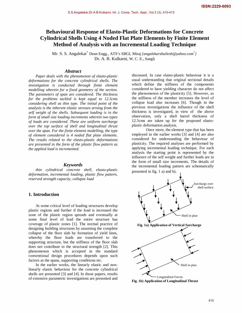
For this case the detailed description of spread of plastic zone is indicated in the fig. 2. First number indicates element number, while second number indicates load stage at which yielding takes place of that particular element.
It is of interest to investigate the percentage of the total surface developing plastic zone with the amount of applied load. In fig. 3 corresponding detail is presented.
]
4-55 8-62 12-66 3-75 7-88 2-96
1&10-105 5-109 9-110 6-141 11-249
Fig. 2 Details of the spread of Plastic Zone with the Application of Vertical Surcharge for Span Ratio 1 by 4 noded Plate Element
0
50
100
150
200
250
300
0.00% 20.00% 40.00% 60.00% 80.00% 100.00% 120.00%Plasticity %
load i
n KN
Fig.3 Percentage of Surface Developing Plastic Zone with Vertical Surcharge for Span Ratio 1by 4 noded Plate Element
S.S.Angalekar,Dr.A.B.Kulkarni, Int. J. Comp. Tech. Appl., Vol 2 (3), 410-413
411
ISSN:2229-6093
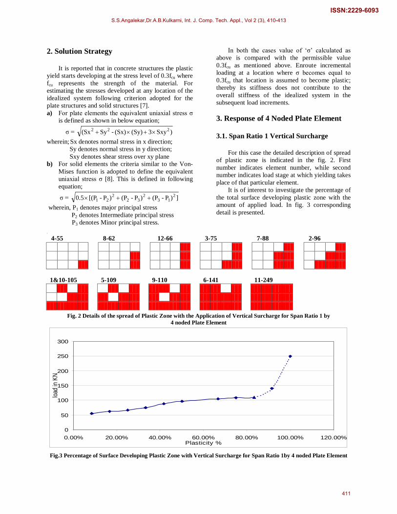
3.2. Span Ratio 1 Longitudinal Force
0
200
400
600
800
1000
1200
1400
1600
0.00% 20.00% 40.00% 60.00% 80.00% 100.00% 120.00%Plasticity %
Load
in KN
Fig. 4 Percentage of Total Surface Developing Plastic zone with Application of Longitudinal Force for Span Ratio 1 by 4 noded Plate Element
0
10
20
30
40
50
60
70
0.00% 20.00% 40.00% 60.00% 80.00% 100.00% 120.00%Plasticity %
Load in K
N
Fig. 5 Percentage of the Total Surface Developing Plastic Zone with the Application of Vertical Surcharge
for Span Ratio 2 by 4 noded Plate Element
0
500
1000
1500
2000
2500
0.00% 20.00% 40.00% 60.00% 80.00% 100.00% 120.00%
Plasticity %
Lo
ad
in K
N
Fig. 6 Percentage of the Total Surface Developing Plastic Zone with the Application of Longitudinal Force
for Span Ratio 2 by 4 noded Plate Element
0
20
40
60
80
100
120
140
0.00% 20.00% 40.00% 60.00% 80.00% 100.00% 120.00%Plasticity %
Load
in K
N
Fig. 7 Percentage of the Total Surface Developing Plastic Zone with the Application of Vertical Surcharge
for Span Ratio 3 by 4 noded Plate Element
0
200
400
600
800
1000
1200
1400
1600
0.00% 20.00% 40.00% 60.00% 80.00% 100.00% 120.00%Plasticity %
Load
in K
N
Fig. 8 Percentage of the Total Surface Developing Plastic Zone with the Application of Longitudinal Force
for Span Ratio 3 by 4 noded Plate Element
S.S.Angalekar,Dr.A.B.Kulkarni, Int. J. Comp. Tech. Appl., Vol 2 (3), 410-413
412
ISSN:2229-6093
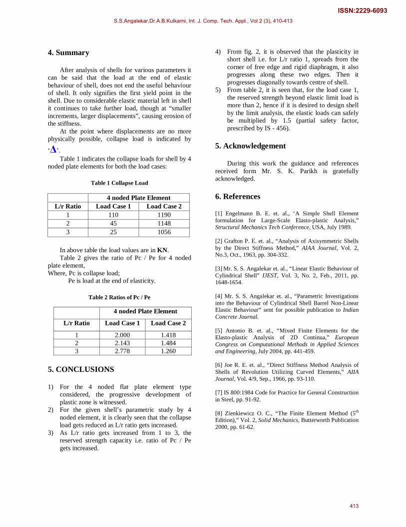
4. Summary
After analysis of shells for various parameters it can be said that the load at the end of elastic behaviour of shell, does not end the useful behaviour of shell. It only signifies the first yield point in the shell. Due to considerable elastic material left in shell it continues to take further load, though at “smaller increments, larger displacements”, causing erosion of the stiffness.
At the point where displacements are no more physically possible, collapse load is indicated by
‘Δ’. Table 1 indicates the collapse loads for shell by 4
noded plate elements for both the load cases:
Table 1 Collapse Load
In above table the load values are in KN. Table 2 gives the ratio of Pc / Pe for 4 noded
plate element, Where, Pc is collapse load;
Pe is load at the end of elasticity.
Table 2 Ratios of Pc / Pe
5. CONCLUSIONS 1) For the 4 noded flat plate element type
considered, the progressive development of plastic zone is witnessed.
2) For the given shell’s parametric study by 4 noded element, it is clearly seen that the collapse load gets reduced as L/r ratio gets increased.
3) As L/r ratio gets increased from 1 to 3, the reserved strength capacity i.e. ratio of Pc / Pe gets increased.
4) From fig. 2, it is observed that the plasticity in short shell i.e. for L/r ratio 1, spreads from the corner of free edge and rigid diaphragm, it also progresses along these two edges. Then it progresses diagonally towards centre of shell.
5) From table 2, it is seen that, for the load case 1, the reserved strength beyond elastic limit load is more than 2, hence if it is desired to design shell by the limit analysis, the elastic loads can safely be multiplied by 1.5 (partial safety factor, prescribed by IS - 456).
5. Acknowledgement
During this work the guidance and references received form Mr. S. K. Parikh is gratefully acknowledged. 6. References [1] Engelmann B. E. et. al., ‘A Simple Shell Element formulation for Large-Scale Elasto-plastic Analysis,” Structural Mechanics Tech Conference, USA, July 1989. [2] Grafton P. E. et. al., “Analysis of Axisymmetric Shells by the Direct Stiffness Method,” AIAA Journal, Vol. 2, No.3, Oct., 1963, pp. 304-332. [3] Mr. S. S. Angalekar et. al., “Linear Elastic Behaviour of Cylindrical Shell” IJEST, Vol. 3, No. 2, Feb., 2011, pp. 1648-1654. [4] Mr. S. S. Angalekar et. al., “Parametric Investigations into the Behaviour of Cylindrical Shell Barrel Non-Linear Elastic Behaviour” sent for possible publication to Indian Concrete Journal. [5] Antonio B. et. al., “Mixed Finite Elements for the Elasto-plastic Analysis of 2D Continua,” European Congress on Computational Methods in Applied Sciences and Engineering, July 2004, pp. 441-459. [6] Joe R. E. et. al., “Direct Stiffness Method Analysis of Shells of Revolution Utilizing Curved Elements,” AIIA Journal, Vol. 4/9, Sep., 1966, pp. 93-110. [7] IS 800:1984 Code for Practice for General Construction in Steel, pp. 91-92. [8] Zienkiewicz O. C., “The Finite Element Method (5th
Edition),” Vol. 2, Solid Mechanics, Butterworth Publication 2000, pp. 61-62.
4 noded Plate Element L/r Ratio Load Case 1 Load Case 2
1 110 1190 2 45 1148 3 25 1056
4 noded Plate Element
L/r Ratio Load Case 1 Load Case 2
1 2.000 1.418 2 2.143 1.484 3 2.778 1.260
S.S.Angalekar,Dr.A.B.Kulkarni, Int. J. Comp. Tech. Appl., Vol 2 (3), 410-413
413
ISSN:2229-6093

![A.L. Eterovic - K.J. Bathe ON LARGE STRAIN ELASTO-PLASTIC ...web.mit.edu/kjb/www/.../On_Large_Strain_Elasto-Plastic_Analysis_wit… · large strain elasto-plastic analysis [2] and](https://img.pdfslide.net/doc/110x75/5fe346b1eba6c44579738db9/al-eterovic-kj-bathe-on-large-strain-elasto-plastic-webmitedukjbwwwonlargestrainelasto-plasticanalysiswit.jpg)


![An image-based method for modeling the elasto-plastic ... · microstructure. Extensions of the Taylor model to elasto-plastic [4], visco-plastic [5], and finite elasto-viscoplastic](https://img.pdfslide.net/doc/110x75/5f1d0763daf4b82b9b0a0a49/an-image-based-method-for-modeling-the-elasto-plastic-microstructure-extensions.jpg)