Embed Size (px)
Citation preview

Aa
RAa
b
a
ARRAA
KMFUTC
1
acppaomac(upi
0h
Journal of Materials Processing Technology 214 (2014) 906– 915
Contents lists available at ScienceDirect
Journal of Materials Processing Technology
j o ur nal homep age : www.elsev ier .com/ locate / jmatprotec
nalysis of a free machining �+� titanium alloy using conventionalnd ultrasonically assisted turning
iaz Muhammada, Mohammad Sajid Hussainb, Agostino Maurottoa, Carsten Siemersb,nish Roya,∗, Vadim V. Silberschmidta
Wolfson School of Mechanical and Manufacturing Engineering, Loughborough University, Loughborough, Leicestershire LE11 3TU, UKInstitut fuer Werkstoffe, Technische Universitaet Braunschweig, Langer Kamp 8, D-38106 Braunschweig, Germany
r t i c l e i n f o
rticle history:eceived 1 July 2013eceived in revised form 7 November 2013ccepted 3 December 2013vailable online 11 December 2013
eywords:achinability
ree-machining alloyltrasonically assisted turningitanium alloyhip formation process
a b s t r a c t
Rapid advancements in power generation and aviation industries have witnessed a widespread use oftitanium and its alloys in many applications. This is primarily due to their excellent mechanical propertiesincluding, amongst other, high strength-to-density ratio, outstanding fatigue properties and corrosionresistance with the ability to withstand moderately high temperatures. However, this combination ofproperties results in poor machinability of the material, increasing the cost of components machined withconventional cutting techniques. Recently, Ti 6Al 2Sn 4Zr 6Mo, a modern titanium alloy with improvedmechanical properties, has been introduced as a possible replacement of Ti 6Al 4V in aerospace industry.However, its poor machinability and formation of long chips in conventional turning are main limitationsfor its wide-spread application. Therefore, a new alloy based on Ti 6Al 2Sn 4Zr 6Mo, namely Ti 6Al7Zr 6Mo 0.9La, was developed; it shows enhanced machinability generating short chips during metalcutting, which prevents entanglement with cutting tools improving productivity. To further enhance the
machinability of this material, a novel hybrid machining technique called ultrasonically assisted turning(UAT) was used. Experimental investigations were carried out to study the machinability, chip shapes,cutting forces, temperature in the process zone and surface roughness for conventional and ultrasonicallyassisted turning of both alloys. UAT shows improved machinability with reduced nominal cutting forces,improved surface roughness of the machined workpiece and generation of shorter chips when comparedto conventional machining conditions.. Introduction
In recent decades, titanium alloys have gained widespreadpplication in the aerospace, power-generation, biomedical andhemical industries, primarily due to a balanced set of desirableroperties, such as light weight, high strength, excellent fatigueerformance and resistance to an aggressive environment (Petersnd Leyens, 2002). However, the main disadvantage of manufacturef titanium components is its poor machinability in conventionalachining operations. The tool life is short in turning of titanium
lloys due to their high strength, low thermal conductivity andhemical reactivity with tool materials at elevated temperatureArrazola et al., 2009). In addition, a relatively low Young’s mod-
lus of titanium alloys leads to spring-back and chatter leading tooor surface quality of the finished product. Finally, during turn-ng and drilling, long continuous chips are produced, causing their
∗ Corresponding author. Tel.: +44 1509227637; fax: +44 1509227648.E-mail address: [email protected] (A. Roy).
924-0136/$ – see front matter. Crown Copyright © 2013 Published by Elsevier B.V. All rittp://dx.doi.org/10.1016/j.jmatprotec.2013.12.002
Crown Copyright © 2013 Published by Elsevier B.V. All rights reserved.
entanglement with the cutting tool and making automated machin-ing almost impossible (Donachie, 2004).
This necessitates the use of low cutting speeds and feeds in con-ventional machining operations of Ti components, which lead toreduced productivity and increased component costs. The recom-mended cutting speeds and feed rates for finishing processes are inthe range of 0.2–0.63 m/s and 0.15–0.2 mm/rev, respectively, fortitanium alloys (Donachie, 2004). In addition, the time spent toremove chip entanglement from the tool and workpiece increasesthe production time.
In titanium cutting, chip morphology is one of the most impor-tant factors affected by machining parameters (Sima and Özel,2010). In general, its depends strongly on several parameters,including cutting speed, feed rate, depth of cut, tool geome-try and material properties of the tools and titanium workpiece.Komanduri and Brown (1981) classified the chip morphology intocontinuous chips, having a constant chips’ thickness, segmented
chips, showing a saw-tooth like structure and discontinuouschips (fully separated segments) employing the above parameters.Mostly, segmented or discontinuous chip formation was obtainedduring high-speed cutting of titanium alloys (Shaw and Vyas, 1998).ghts reserved.
ls Proc
Ibta
iLcncspf
apbihbmtathdiaiumtcpflmaw
iatmibrcR(abip(wmtsHitswiid
R. Muhammad et al. / Journal of Materia
n segmented chips, a narrow zone of high deformation appearedetween the segments, the so-called adiabatic shear-band. Duringhe cutting process, deformation localizes in the primary shear zonend temperature increase significantly (Siemers et al., 2012).
In the past, the chip-formation process of titanium alloys wasntensively studied by means of cutting experiments (Sutter andist, 2013) and simulations (Calamaz et al., 2008). Titanium alloysontaining large amounts of �-phase at room temperature (�-,ear-� and (�+�)-alloys) produced segmented chips for almost allutting processes and a wide range of cutting conditions, whereasolution-treated metastable �- and �-alloys showed a cuttingarameter-dependent change from continuous to segmented chipormation (Siemers et al., 2011b).
There are various ways to improve machinability of titaniumlloys, e.g. by external processes such as the application of high-ressure coolant during cutting operations (Ezugwua et al., 2005),y the use of enhanced machining techniques such as ultrason-
cally assisted turning (UAT) (Maurotto et al., 2013) and otherybrid machining techniques (Rahman Rashid et al., 2012a,b) ory internal processes, e.g. by improving the machinability by alloyodification without significant changes to other material proper-
ies (Siemers et al., 2007). The improvements based on the firstpproach are limited. This can be explained by the high con-act pressure between tools and chips in combination with loweat conductivity of titanium that prevents application of coolantsirectly to the process zone. Additionally, in the recent years, the
ncreased environmental awareness and growing costs have led to critical re-consideration of conventional cooling lubrication usedn machining processes. The costs related to cutting fluids in a man-facturing operation range from 10% to 20% of the total costs of theanufactured workpiece, whereas some researchers have claimed
hat the costs associated with cutting fluids are higher than theost of cutting tools (Shokrani et al., 2012). Most of these costs arerimarily due to environmental requirements: handling of cuttinguids as well as their disposal must obey the strict rules of environ-ental protections. Therefore, green manufacturing has become
ttractive to industries as an alternative to conventional machiningith flood supply of cutting fluid (Weinert et al., 2004).
In recent decades, a novel machining technique called ultrason-cally assisted turning (UAT), in which low-energy vibro-impactsre superimposed on the movement of cutting tool, preferably inhe cutting direction, has shown promise as a viable technique for
achining high-strength alloys (Babitsky et al., 2004). Ultrason-cally assisted machining was first introduced in the late 1960sy Skelton (Skelton, 1968). A significant improvement in surfaceoughness (Maurotto et al., 2012) and substantial reduction inutting forces was observed in UAT (Muhammad et al., 2013a).ecently, a variant of UAT was proposed by Muhammad et al.2012b) called hot ultrasonically assisted turning, combining thedvantages of hot-machining with those of UAT to yield furtherenefits in machining intractable alloys such as Ti-15333. There
s considerable research work on elliptical ultrasonic machiningrocesses. One of the earliest works by Shamoto and Moriwaki1994) discussed the advantages of elliptical vibration cuttingith regard to reduction of cutting forces and chip thickness inachining of copper. More recently, Zhang et al. (2012) studied
he effect of elliptical cutting of hardened steels showing con-iderable improvements compared to conventional machining.owever, major disadvantages of this technique lies in kinemat-
cs of the tool motion during a vibratory cycle. The motion of theool inevitably ends up cutting periodic grooves in the workpieceurface, ultimately affecting the surface quality of the machined
orkpiece. Reducing the feed rate or the vibration amplitude wouldmprove surface quality but this would ultimately affect machin-ng time. The developed UAT process, discussed in this paper,oes not suffer from the said disadvantage of elliptical vibratory
essing Technology 214 (2014) 906– 915 907
machining. Recently, analytical models were developed for ultra-sonically assisted oblique turning (Nategh et al., 2012) and 2Dvibrational assisted turning (Zhang et al., 2012) to investigate thebenefit of this novel machining process.
Alloy modification is another technique in improving machin-ability, which is more difficult to perform as small changes inthe chemical composition can lead to large, unexpected mechan-ical effects (Hussain et al., 2013). That being said, few attemptshave been undertaken to develop free-machining titanium alloys.Kitayama and co-workers, added different rare-earth metals (REM)together with phosphorus (P) or sulphur (S) to achieve distribu-tion of metal sulphide particles in a titanium alloy (Kitayama et al.,1992). Siemers and co-workers, improved machinability of Ti 6Al4V (Ti-64) alloy by the addition of small amounts of cerium (Ce),erbium (Er), lanthanum (La) and neodymium (Nd) (Siemers et al.,2003). It was found that the addition of 0.9% Ce, La or Nd led to theformation of short chips due to softening and melting of rare-earth-metal precipitates once the temperature in the primary shear zoneincrease. This resulted in a decrease in adhesion between segmentsand chip separation during further progress of the tool. Addition ofEr did not improve machinability as its melting point is too high(Siemers et al., 2011a).
Interestingly, it was observed that whenever tin (Sn) waspresent in the alloys, addition of REM did not improve machin-ability as Sn and La form intermetallics like La5Sn3, which havesoftening temperature above 1500 ◦C (Siemers et al., 2009). In Sn-containing alloys, Sn can be replaced by zirconium (Zr) ensuringthat REM particles are present in the alloys. Similar attempts weremade with commercially pure titanium (CP-Titanium Grade 2 andGrade 4), Ti 6Al 2Sn 4Zr 2Mo 0.08Si (Ti-6242S), Ti 15V 3Al 3Cr 3Sn(Ti-15333) and Ti 5Al 5V 5Mo 3Cr 0.5Fe (Ti5553) (Siemers et al.,2011a).
At present, up to 70% of titanium alloys produced and usedare in the form of Ti-64. Due to its enhanced properties, Ti-6246alloy will partly replace Ti-64 in aerospace engineering in thenear future, especially, in aircraft engine components and airframestructures (Donachie, 2004). However, long chips obtained in turn-ing or drilling of Ti-6246 are the main obstacles for automatedmachining operations. Therefore, there is an obvious need (1) tosuggest new machining techniques for the production chain and(2) to develop new titanium alloys with similar properties but pro-ducing discontinuous chips in machining.
In the current work, a new variant of Ti-6246, namely, Ti 6Al7Zr 6Mo 0.9La (designated as Ti-676-0.9La) was developed andmachined with a novel machining technique – UAT – to improvemachining operations and demonstrate its viability for automaticmanufacture. The obtained results are compared with those for thestandard Ti-6246 alloy.
2. Materials and alloy production
The standard Ti-6246 alloy was produced by the GfE-Metalle andMaterialien GmbH in Nuremberg, Germany. After 2× vacuum arcremelting (VAR), the alloy was forged from diameter approximately200 mm to diameter 75 mm in the two-phase field followed by aircooling, stress-relief annealing and stripping. To produce compa-rable results in the machining experiments, this alloy had beenremelted once in a plasma-beam cold hearth melter (PB-CHM) fol-lowed by casting and stress-relief annealing (as described for themodified alloy in the following paragraph).
Implementation of alloy modification was achieved in several
stages: (1) 0.9% of La was added to improve machinability (Siemerset al., 2011b). From earlier studies it was known that La and Sngenerated intermetallic phases like La5Sn3. Therefore, to avoidtheir formation, Sn had to be removed from the modified alloy
908 R. Muhammad et al. / Journal of Materials Processing Technology 214 (2014) 906– 915
i-676
wmDnisaowacc
C(TpmhaphTa8(oo
Fo
Fig. 1. Microstructure of T
hich acts as a solid-solution hardener (added to the alloys asetallic Sn) without influencing the �-transus temperature. (2)uring alloy modification, Sn could be replaced by Zr as it doesot have a significant influence on the �-transus temperature and
s used for solid-solution hardening as well. To ensure similar solid-olution hardening and �-transus temperatures in the modifiedlloy, checked by ThermoCalc® simulations, 3% Zr was used insteadf 2% Sn meaning that the overall Zr content in the modified alloyas increased to 7%. (3) As no multi-phase reactions between Mo
nd other alloying elements occurred, the Mo content was keptonstant. This led to final composition of Ti 6Al 7Zr 6Mo-0.9Laontaining 6% Al, 7% Zr, 6% Mo, 0.9% La besides titanium.
The modified alloy was produced by plasma arc melting (PB-HM) in a laboratory furnace with a capacity of about 350 g TiRosler et al., 2004). The Ti-676-0.9La alloy was produced from CP-i Grade 2 following ASTM B 348, pure Zr (99.9%), an Al-Mo (52:48)re alloy to avoid high-density inclusion (HDI) formation duringelting, pure Al (99.95%) and pure La (99.9%). To ensure sufficient
omogeneity of the alloy, it was twice turned by 180◦ and remoltenfter the first melting. The alloy was cast into a water-cooled cop-er crucible of cylindrical shape (fast cooling). The resulting rodsad a diameter of 25 mm and a length of approximately 50 mm.o remove residual stresses remaining after the casting processnd to dissolve possible Ti3Al phases, all samples were annealed at
80 ◦C for 1 h in inert gas atmosphere followed by furnace coolingsolution-treated state). The investigation of mechanical propertiesf Ti-676-0.9 in comparison to Ti-6246 is underway. Similar levelsf hardness indicate that the tensile strength of both alloys shouldig. 2. (a) SEM microstructure showing lanthanum particles precipitated at grain boundarf the particles (Hussain et al., 2013).
-0.9La (a) and Ti-6246 (b).
be similar as well. The solution-treated bars of both alloys weresubjected to experiments employing conventional turning (CT) andUAT techniques.
2.1. Microstructure and phase analysis
Microstructure and phase studies of the two alloys were carriedout, and equiaxed grains with a fine lamellar substructures wereobserved (see Fig. 1). Additionally, in the modified alloy, discrete,globular La particles were found, mainly at the grain boundaries(Fig. 1a). This is naturally explained by low solvability of La in Tiin the liquid and solid state. As the melting point of La is lowerthan that of Ti, a Ti matrix develops, during crystallization and theremaining melt is enriched in La, leading to trapping of liquid La onthe grain boundaries that finally crystallizes. The average particlesize was about 2 �m (Fig. 2a). Hard XRD investigations at BW5,HASYLAB, DESY in Germany proved that the La particles were ofmetallic nature (Fig. 2b).
The average grain sizes of Ti-676-0.9La were 43 �m ± 12 �m and147 �m ± 13 �m for Ti-6246 alloy (see Fig. 1). This indicates thatthe La particles either act as additional nuclei during crystallizationand/or hinder grain growth during cooling of the modified alloy inthe solid state.
Based on these observations, heat treatment of both alloys was
carried out at different temperatures – slightly below and abovetheir �-transus temperature to study their grain-size stability. Itwas found that no grain growth occurred in Ti-676-0.9La at temper-atures below �-transus whereas severe grain growth was observedies. (b) Hard-XRD patterns for Ti-6246 and Ti-676-0.9La indicate the metallic nature

R. Muhammad et al. / Journal of Materials Processing Technology 214 (2014) 906– 915 909
F
ict
3
itfr4ra
Twemtfufi
4
Uastte(sto
TC
ig. 3. Grain size for various temperatures in both alloys (Hussain et al., 2013).
n the standard Ti-6246 alloy in all heat treatments (Fig. 3). Thisonfirms the grain size stabilization effect of lanthanum in (�+�)-itanium alloys (Hussain et al., 2013).
. Cutting tool and cutting conditions
In cutting tests of the studied alloys, cemented-carbide cuttingnserts with a ceramic coating of titanium-aluminium-nitride onop of a layer of titanium-nitride (CP500) were used, as suggestedor cutting depths ranging from 0.2 mm to 0.300 mm with a feedate of 0.05 mm/rev to 0.25 mm/rev and cutting speeds of about5 m/min (as specified by the manufacturer). The tool had a noseadius of 0.8 mm, a rake angle of approximately 14◦ and clearancengle of 0◦.
The cutting conditions used in the experiments are listed inable 1. Round bars of both alloys were initially turned on a latheith coolant to remove the residual effect of manufacturing and
nvironmental conditions on the studied alloys. The ingot bars wereounted on a Harrison lathe and the eccentricity was adjusted with
he help of a mechanical dial gauge. Experiments were carried outor CT and UAT for various cutting speeds at a depth of cut of 0.2 mmsing a relatively low feed rate (t) of 0.1 mm/rev recommended fornishing operations of Ti-alloys (Donachie, 2004).
. Experimental setup
A customized Harrison 300 lathe was used to carry out CT andAT of both alloys as shown in Fig. 4. The lathe was modified with
customized ultrasonic transducer fixed to a cross wave-guide touperimpose ultrasonic vibration on the movement of a cuttingool, in UAT (Muhammad et al., 2012a). A schematic diagram ofhe experimental setup is shown in Fig. 4a. A digital signal gen-rator was used to generate a low-current driving signal of 10 V
peak-to-peak), which was amplified for driving the transducer. Theignal was then supplied to the piezoelectric rings converting elec-rical energy into mechanical vibration with a maximum efficiencyf 0.95. A non-contact measurement technique (Poly-tech laserable 1utting conditions used in experiments.
Parameters Magnitude
Cutting speed, V (m/min) 10; 30; 60Depth of cut, ap (mm) 0.2Feed rate, fr (mm/rev) 0.1Vibration frequency in UAT, f (kHz) 20Vibration amplitude in UAT, a (�m) 10
Fig. 4. Schematic diagram of the experimental setup (a); experimental setup for CTand UAT (b).
vibro-meter) was used to monitor vibration parameters in theturning tests. Cutting tests were performed for both machiningtechniques, and each experiment was repeated at least five timesto get good statistical data. The cutting forces were measuredwith a three-component Kistler dynamometer (KIAG-SWISS Type-9257A), fixed to the ultrasonic head assembly to record the cuttingforces (see Fig. 4b). The dynamometer has a sensitivity of ±0.1 N andcan measure the two components of force Fx and Fy, in turning. Theoutput signals from the dynamometer were supplied to a Kistler5001 amplifier to convert them to high-amplitude signals. Theamplified signals were processed in an advanced four-channel dig-ital oscilloscope (analogue-to-digital converter), Picoscope 4424,and finally recorded in a computer (Fig. 4a). The data-acquisitionsystem yields an average of the force over a large number of cyclesof ultrasonic vibration as recorded from the dynamometer. Forcutting force analysis, each experimental test lasted for approxi-mately 70 s. Within the first 10–15 s, the depth of cut was set toa desired magnitude followed by CT for 25–30 s as shown in theforce history diagram (Fig. 5). During the test, ultrasonic vibrationwas switched on after 40 s and lasted for approximately 20 s beforebeing switched off to recover CT the regime for the rest of 10 s.
Additionally, the amount of heat generated in CT and UAT inthe process zone in turning of both alloys, which has a significanteffect on the sub-surface deformation, metallurgical structure andtool life, needed to be investigated. Therefore, in this study, theFLIR ThermaCAMTM SC3000 camera was used to carry out thermalanalysis. The system was mounted on a special fixture, and dataobtained for CT and UAT were recorded (Fig. 6), using a continuousmode operation. The data were later analyzed for various cuttingconditions, and only average temperature values were used in the
analysis.Post-turning, analysis was carried out using Zygo® interferome-try (NewViewTM 5000 series) to characterize the machined surfacefor CT and UAT for both alloys. In addition to that, chip samples

910 R. Muhammad et al. / Journal of Materials Processing Technology 214 (2014) 906– 915
F
w(
5
5
wgtcwde1
F
ig. 5. Force history in CT and UAT for Ti-676-0.9La at ap = 0.2 mm and V = 10 m/min.
ere collected and analyzed using scanning electronic microscopySEM).
. Results and discussion
.1. Chip morphology
In the turning experiments at various cutting conditions, chipsere collected and analyzed with respect to their morphology and
eometry. In machining of the standard Ti-6246 alloy, long con-inuous chips were developed in CT and UAT at various cuttingonditions. Chips of the modified alloy (Ti-676-0.9La), in contrast,
ere discontinuous in both CT and UAT as shown in Fig. 7. Theifference in the length of the chips is clearly visible and was appar-nt for various cutting conditions, even at low cutting speeds (e.g.0 m/min).ig. 7. Chip formed in turning processes: Ti-6246 in CT (a); Ti-6246 in UAT (b); Ti-676-0.9
Fig. 6. Temperature history for CT and UAT of Ti-6246 at ap = 0.2 mm for variouscutting speeds.
The formation of short chips in the modified alloy in CT andUAT can be explained as follows: during chip segmentation, thehigh temperature in the shear bands softens drastically or evenmelts the metallic lanthanum particles that are present in the
in CT (c); Ti-676-0.9 in UAT (d). The difference in the chips’ length is clearly visible.

R. Muhammad et al. / Journal of Materials Processing Technology 214 (2014) 906– 915 911
and Ti
zbttcniowc
F
Fa
cess, chip compression ratio (�) was analyzed for both alloys. Crosssections of chips of the two studied titanium alloys were analyzedwith optical microscopy for various cutting parameters (Fig. 9). Todo so, quantitative image analyses were performed (with ImagJ
Fig. 8. Chip morphology for UAT of Ti-6246 (a)
one of localized deformation. This results in diminished adhesionetween the segments, which fall apart during further progress ofhe tool. In UAT of the modified alloy, vibro-impact events at theool–workpiece-interface pulverize the chip, and shorter and lessurved chips are obtained when compared to CT. Since in Ti-6246o La particles are present, long continuous chips are formed both
n CT and UAT. SEM analyses of the chips show that chip separationccurs in almost each segment in case of the Ti-676-0.9La alloy,hereas in Ti-6246 good cohesion was observed in the segmented
hip (Fig. 8).
ig. 9. Definition of geometrical parameters used for comparison of different chips.
ig. 10. Chip compression ratio for both alloys machined with CT and UAT atp = 0.2 mm for various cutting speeds.
-676-0.9La (b) at ap = 0.2 mm and V = 10 m/min.
5.2. Effect of cutting parameters on chip geometry
In order to get a better understanding of the chip formation pro-
Fig. 11. Cutting forces in CT and UAT of Ti-6246 at ap = 0.2 mm for various cuttingspeeds.
Fig. 12. Cutting forces in CT and UAT of Ti-676-0.9La at ap = 0.2 mm for variouscutting speeds.
9 ls Processing Technology 214 (2014) 906– 915
sf
�
wa
swiivCTdap
5
a(inacAw
12 R. Muhammad et al. / Journal of Materia
oftware), and the chip compression ratio was calculated using theollowing equation.
= hmax + hmin
2dc, (1)
here dc is the chip thickness and hmax and hmin are the maximumnd minimum heights of the segment, respectively.
The chip compression ratio increased with an increase in cuttingpeed for both alloys. However, a higher chip compression ratioas observed in UAT when compared to CT in both alloys as shown
n Fig. 10. The main reason for the high compression ratio in UATs the additional energy superimposed on the tool in the form ofibration, resulting in a relatively higher tool velocity compared toT. Furthermore, a higher chip compression ratio was observed ini-676-0.9La when compared to Ti-6246 in both CT and UAT; this isue to the presence of lanthanum particles at the grain boundariesnd in the shear bands changing kinematics of the chip formationrocesses and separation.
.3. Cutting forces
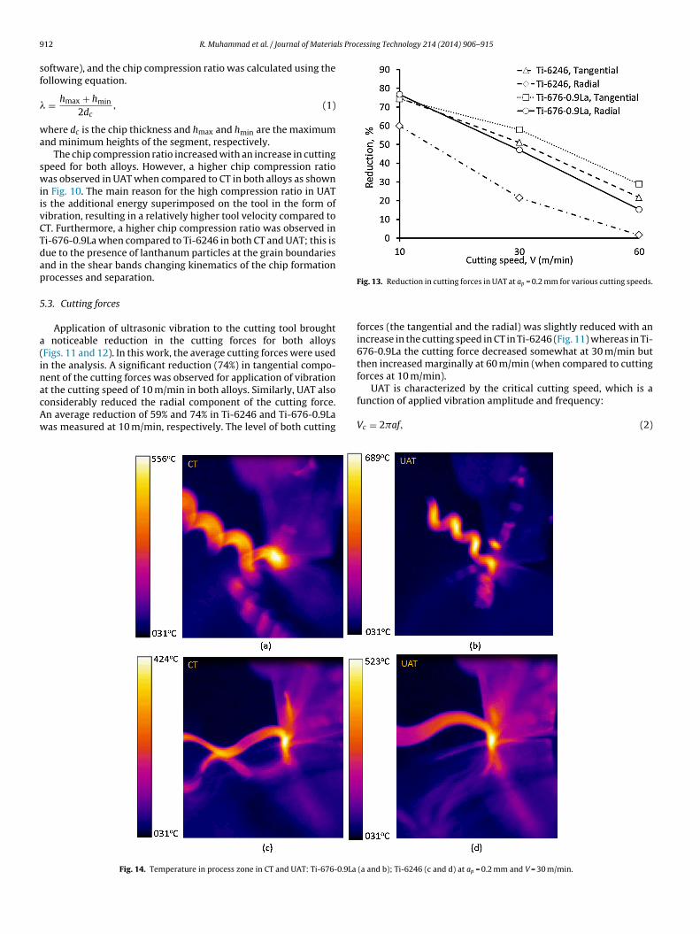
Application of ultrasonic vibration to the cutting tool brought noticeable reduction in the cutting forces for both alloysFigs. 11 and 12). In this work, the average cutting forces were usedn the analysis. A significant reduction (74%) in tangential compo-ent of the cutting forces was observed for application of vibration
t the cutting speed of 10 m/min in both alloys. Similarly, UAT alsoonsiderably reduced the radial component of the cutting force.n average reduction of 59% and 74% in Ti-6246 and Ti-676-0.9Laas measured at 10 m/min, respectively. The level of both cuttingFig. 14. Temperature in process zone in CT and UAT: Ti-676-0.9La
Fig. 13. Reduction in cutting forces in UAT at ap = 0.2 mm for various cutting speeds.
forces (the tangential and the radial) was slightly reduced with anincrease in the cutting speed in CT in Ti-6246 (Fig. 11) whereas in Ti-676-0.9La the cutting force decreased somewhat at 30 m/min butthen increased marginally at 60 m/min (when compared to cuttingforces at 10 m/min).
UAT is characterized by the critical cutting speed, which is a
function of applied vibration amplitude and frequency:Vc = 2�af, (2)
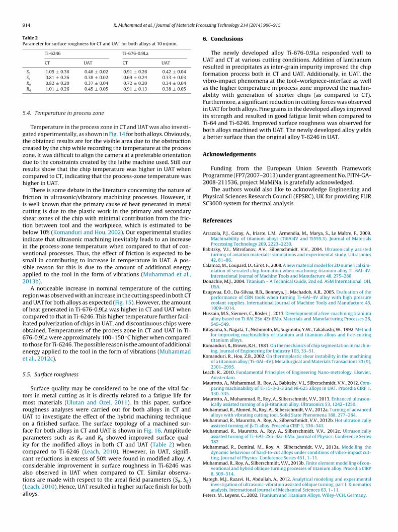
(a and b); Ti-6246 (c and d) at ap = 0.2 mm and V = 30 m/min.

R. Muhammad et al. / Journal of Materials Proc
Fa
ig. 15. Temperature in process zone in CT and UAT for Ti-6246 and Ti-676-0.9Lat ap = 0.2 mm for various cutting speeds.
Fig. 16. Surface profile scan for CT and UAT for both a
essing Technology 214 (2014) 906– 915 913
where f is the frequency and a is an amplitude of vibration super-imposed on the cutting tool. In the current experimental setup,the critical velocity is calculated to be 75.32 m/min. In UAT, withan increase in the cutting speed, separation between the tooland workpiece is reduced, causing a decline in force reduction.Therefore, it is no surprise that the cutting forces increased withthe increased cutting speed and, ultimately, the reduction in cut-ting forces vanished near the critical velocity limit (Fig. 13). At10–30 m/min, the reduction in the tangential component of forceswas 51% and 57% for Ti-6246 and Ti-676-0.9La, respectively, whencompared to CT. Similarly, a reduction of 21% and 47% in the radialcutting forces was observed for the same cutting speed. At a highercutting speed of 60 m/min, a considerable reduction of 21% and 28%,respectively, in the tangential component of forces was measuredfor Ti-6246 and Ti-676-0.9La. However, the reduction in the radialcomponent of force in Ti-6246 was significantly lower comparedto that for Ti-676-0.9La (15%). As cutting velocity is still lower than
the critical velocity of the system, therefore, caused a reduction incutting forces.lloys at ap = 0.2 mm for various cutting speeds.
914 R. Muhammad et al. / Journal of Materials Proc
Table 2Parameter for surface roughness for CT and UAT for both alloys at 10 m/min.
Ti-6246 Ti-676-0.9La
CT UAT CT UAT
Sq 1.05 ± 0.36 0.46 ± 0.02 0.91 ± 0.26 0.42 ± 0.04Sa 0.81 ± 0.26 0.38 ± 0.02 0.69 ± 0.24 0.33 ± 0.03R 0.82 ± 0.20 0.37 ± 0.04 0.72 ± 0.20 0.34 ± 0.04
5
gtczdrch
ficstbiivssa2
raocio6tee
5
tmrUofpicccat(a
a
Rq 1.01 ± 0.26 0.45 ± 0.05 0.91 ± 0.13 0.38 ± 0.05
.4. Temperature in process zone
Temperature in the process zone in CT and UAT was also investi-ated experimentally, as shown in Fig. 14 for both alloys. Obviously,he obtained results are for the visible area due to the obstructionreated by the chip while recording the temperature at the processone. It was difficult to align the camera at a preferable orientationue to the constraints created by the lathe machine used. Still ouresults show that the chip temperature was higher in UAT whenompared to CT, indicating that the process-zone temperature wasigher in UAT.
There is some debate in the literature concerning the nature ofriction in ultrasonic/vibratory machining processes. However, its well known that the primary cause of heat generated in metalutting is due to the plastic work in the primary and secondaryhear zones of the chip with minimal contribution from the fric-ion between tool and the workpiece, which is estimated to beelow 10% (Komanduri and Hou, 2002). Our experimental studies
ndicate that ultrasonic machining inevitably leads to an increasen the process-zone temperature when compared to that of con-entional processes. Thus, the effect of friction is expected to bemall in contributing to increase in temperature in UAT. A pos-ible reason for this is due to the amount of additional energypplied to the tool in the form of vibrations (Muhammad et al.,013b).
A noticeable increase in nominal temperature of the cuttingegion was observed with an increase in the cutting speed in both CTnd UAT for both alloys as expected (Fig. 15). However, the amountf heat generated in Ti-676-0.9La was higher in CT and UAT whenompared to that in Ti-6246. This higher temperature further facil-tated pulverization of chips in UAT, and discontinuous chips werebtained. Temperatures of the process zone in CT and UAT in Ti-76-0.9La were approximately 100–150 ◦C higher when comparedo those for Ti-6246. The possible reason is the amount of additionalnergy applied to the tool in the form of vibrations (Muhammadt al., 2012c).
.5. Surface roughness
Surface quality may be considered to be one of the vital fac-ors in metal cutting as it is directly related to a fatigue life for
ost materials (Ulutan and Ozel, 2011). In this paper, surfaceoughness analyses were carried out for both alloys in CT andAT to investigate the effect of the hybrid machining techniquen a finished surface. The surface topology of a machined sur-ace for both alloys in CT and UAT is shown in Fig. 16. Amplitudearameters such as Ra and Rq showed improved surface qual-
ty for the modified alloys in both CT and UAT (Table 2) whenompared to Ti-6246 (Leach, 2010). However, in UAT, signifi-ant reductions in excess of 50% were found in modified alloy. Aonsiderable improvement in surface roughness in Ti-6246 was
lso observed in UAT when compared to CT. Similar observa-ions are made with respect to the areal field parameters (Sa, Sq)Leach, 2010). Hence, UAT resulted in higher surface finish for bothlloys.essing Technology 214 (2014) 906– 915
6. Conclusions
The newly developed alloy Ti-676-0.9La responded well toUAT and CT at various cutting conditions. Addition of lanthanumresulted in precipitates as inter-grain impurity improved the chipformation process both in CT and UAT. Additionally, in UAT, thevibro-impact phenomena at the tool–workpiece-interface as wellas the higher temperature in process zone improved the machin-ability with generation of shorter chips (as compared to CT).Furthermore, a significant reduction in cutting forces was observedin UAT for both alloys. Fine grains in the developed alloys improvedits strength and resulted in good fatigue limit when compared toTi-64 and Ti-6246. Improved surface roughness was observed forboth alloys machined with UAT. The newly developed alloy yieldsa better surface than the original alloy T-6246 in UAT.
Acknowledgements
Funding from the European Union Seventh FrameworkProgramme (FP7/2007–2013) under grant agreement No. PITN-GA-2008-211536, project MaMiNa, is gratefully acknowledged.
The authors would also like to acknowledge Engineering andPhysical Sciences Research Council (EPSRC), UK for providing FLIRSC3000 system for thermal analysis.
References
Arrazola, P.J., Garay, A., Iriarte, L.M., Armendia, M., Marya, S., Le Maître, F., 2009.Machinability of titanium alloys (Ti6Al4V and Ti555.3). Journal of MaterialsProcessing Technology 209, 2223–2230.
Babitsky, V.I., Mitrofanov, A.V., Silberschmidt, V.V., 2004. Ultrasonically assistedturning of aviation materials: simulations and experimental study. Ultrasonics42, 81–86.
Calamaz, M., Coupard, D., Girot, F., 2008. A new material model for 2D numerical sim-ulation of serrated chip formation when machining titanium alloy Ti–6Al–4V.International Journal of Machine Tools and Manufacture 48, 275–288.
Donachie, M.J., 2004. Titanium – A Technical Guide, 2nd ed. ASM International, OH,USA.
Ezugwua, E.O., Da-Silvaa, R.B., Bonneya, J., Machadob, A.R., 2005. Evaluation of theperformance of CBN tools when turning Ti–6Al–4V alloy with high pressurecoolant supplies. International Journal of Machine Tools and Manufacture 45,1009–1014.
Hussain, M.S., Siemers, C., Rösler, J., 2013. Development of a free-machining titaniumalloy based on Ti 6Al 2Sn 4Zr 6Mo. Materials and Manufacturing Processes 28,545–549.
Kitayama, S., Nagata, T., Nishimoto, M., Sugimoto, Y.W., Takahashi, W., 1992. Methodfor improving machinability of titanium and titanium alloys and free-cuttingtitanium alloys.
Komanduri, R., Brown, R.H., 1981. On the mechanics of chip segmentation in machin-ing. Journal of Engineering for Industry 103, 33–51.
Komanduri, R., Hou, Z.B., 2002. On thermoplastic shear instability in the machiningof a titanium alloy (Ti–6Al–4V). Metallurgical and Materials Transactions 33 (9),2301–2995.
Leach, R., 2010. Fundamental Principles of Engineering Nano-metrology. Elsevier,Amsterdam.
Maurotto, A., Muhammad, R., Roy, A., Babitsky, V.I., Silberschmidt, V.V., 2012. Com-paring machinability of Ti-15-3-3-3 and Ni-625 alloys in UAT. Procedia CIRP 1,330–335.
Maurotto, A., Muhammad, R., Roy, A., Silberschmidt, V.V., 2013. Enhanced ultrason-ically assisted turning of a �-titanium alloy. Ultrasonics 53, 1242–1250.
Muhammad, R., Ahmed, N., Roy, A., Silberschmidt, V.V., 2012a. Turning of advancedalloys with vibrating cutting tool. Solid State Phenomena 188, 277–284.
Muhammad, R., Maurotto, A., Roy, A., Silberschmidt, V.V., 2012b. Hot ultrasonicallyassisted turning of �-Ti alloy. Procedia CIRP 1, 336–341.
Muhammad, R., Maurotto, A., Roy, A., Silberschmidt, V.V., 2012c. Ultrasonicallyassisted turning of Ti–6Al–2Sn–4Zr–6Mo. Journal of Physics: Conference Series382.
Muhammad, R., Demiral, M., Roy, A., Silberschmidt, V.V., 2013a. Modelling thedynamic behaviour of hard-to-cut alloys under conditions of vibro-impact cut-ting. Journal of Physics: Conference Series 451, 1–11.
Muhammad, R., Roy, A., Silberschmidt, V.V., 2013b. Finite element modelling of con-ventional and hybrid oblique turning processes of titanium alloy. Procedia CIRP
8, 509–514.Nategh, M.J., Razavi, H., Abdullah, A., 2012. Analytical modeling and experimentalinvestigation of ultrasonic-vibration assisted oblique turning, part I: Kinematicsanalysis. International Journal of Mechanical Sciences 63, 1–11.
Peters, M., Leyens, C., 2002. Titanium and Titanium Alloys. Wiley-VCH, Germany.

ls Proc
R
R
RS
S
S
S
S
S
R. Muhammad et al. / Journal of Materia
ahman Rashid, R.A., Sun, S., Wang, G., Dargusch, M.S., 2012a. The effect of laserpower on the machinability of the Ti–6Cr–5Mo–5V–4Al beta titanium alloyduring laser assisted machining. International Journal of Machine Tools andManufacture 63, 41–43.
ahman Rashid, R.A., Sun, S., Wang, G., Dargusch, M.S., 2012b. An investigation ofcutting forces and cutting temperatures during laser-assisted machining of theTi–6Cr–5Mo–5V–4Al beta titanium alloy. International Journal of Machine Toolsand Manufacture 63, 58–69.
osler, J., Baker, M., Siemers, C., 2004. German Patent DE 103 32 078.hamoto, E., Moriwaki, T., 1994. Study on elliptical vibration cutting. CIRP Annals –
Manufacturing Technology 43, 35–38.haw, M.C., Vyas, A., 1998. The mechanism of chip formation with hard turning steel.
CIRP Annals – Manufacturing Technology 47, 77–82.hokrani, A., Dhokia, V., Newman, S.T., 2012. Environmentally conscious machin-
ing of difficult-to-machine materials with regard to cutting fluids. InternationalJournal of Machine Tools and Manufacture 57, 83–101.
iemers, C., Bäker, M., Mukherji, D., Rösler, J.,2003. Microstructure evolution in shearbands during the chip formation of Ti6Al4V. In: Proceedings of Ti-2003. Wiley-VCH, Weinheim, Germany.
iemers, C., Brunke, F., Laukart, J., Hussain, M.S., Rösler, J., Saksl, K., Zahra, B.,2012. COM2012, Section Rare Earth Metals 2012 , Niagara Falls, Canada,
pp. 281–292.iemers, C., Brunke, F., Stache, M., Laukart, J., Zahra, B., Roesler, J., Rokicki,P., Saksl, K., 2011a. Advanced titanium alloys containing micrometer-sizeparticles. In: 12th World Conference on Titanium (Ti-2011), Beijing, China,pp. 883–887.
essing Technology 214 (2014) 906– 915 915
Siemers, C., Jencus, P., Baeker, M., Roesler, J., Feyerabend, F., 2007. A new free machin-ing titanium alloy containing lanthanum. In: Proceedings of the 11th WorldConference on Titanium (Ti-2007), Kyoto, Japan, pp. 709–712.
Siemers, C., Laukart, J., Zahra, B., Rösler, J., Spotz, Z.K.S., 2011b. Development ofadvanced and free-machining alloys by micrometer-size particle precipitation.Materials Science Forum 690, 262–265.
Siemers, C., Zahra, B., Leemet, T., Rösler, J., 2009. 8th AMMT’09 Conference , St.Petersburg, Russia.
Sima, M., Özel, T., 2010. Modified material constitutive models for serrated chipformation simulations and experimental validation in machining of titaniumalloy Ti–6Al–4V. International Journal of Machine Tools and Manufacture 50,943–960.
Skelton, R.C., 1968. Turning with an oscillating tool. International Journal of MachineTool Design and Research 8, 239–259.
Sutter, G., List, G., 2013. Very high speed cutting of Ti–6Al–4V titanium alloy –change in morphology and mechanism of chip formation. International Journalof Machine Tools and Manufacture 66, 37–43.
Ulutan, D., Ozel, T., 2011. Machining induced surface integrity in titanium and nickelalloys: a review. International Journal of Machine Tools and Manufacture 51,250–280.
Weinert, K., Inasaki, I., Sutherland, J.W., Wakabayashi, T., 2004. Dry machining and
minimum quantity lubrication. CIRP Annals – Manufacturing Technology 53,511–537.Zhang, X., Senthil Kumar, A., Rahman, M., Nath, C., Liu, K., 2012. An analytical forcemodel for orthogonal elliptical vibration cutting technique. Journal of Manufac-turing Processes 14.

![Ultrasonically assisted machining of Titanium alloys · Ultrasonically assisted ... electrical discharge machining (EDM) in milling of Ti alloys [4] ... Superimposing ultrasonic vibration](https://img.pdfslide.net/doc/110x75/5b1e5f9d7f8b9a901f8b8ced/ultrasonically-assisted-machining-of-titanium-alloys-ultrasonically-assisted.jpg)
![A REVIEW ON MACHINING OF TITANIUM BASED … review on machining of titanium based alloys using EDM and WEDM 89 p( 4SeP]RTSFcdSh6T]cTa6A "cS Rev. Adv. Mater. Sci. 36 (2014) 89-111 Corresponding](https://img.pdfslide.net/doc/110x75/5aa4aca57f8b9afa758c3832/a-review-on-machining-of-titanium-based-review-on-machining-of-titanium-based.jpg)


![A REVIEW ON MACHINING OF TITANIUM BASED ALLOYS ...mp.ipme.ru/e-journals/RAMS/no_23614/01_23614_manjaiah.pdfA review on machining of titanium based alloys using EDM and WEDM 89 p( 4SeP]RTSFcdSh6T]cTa6A](https://img.pdfslide.net/doc/110x75/60c7b1dbc85722288063bed5/a-review-on-machining-of-titanium-based-alloys-mpipmerue-journalsramsno236140123614.jpg)