Embed Size (px)
Citation preview
1
Analysis of Acoustic Wave in Homogeneous and Inhomogeneous Media
Using Finite Element Method
Zi-Gui Huang Department of Mechanical Design Engineering, National Formosa University
Taiwan
1. Introduction
Even though the propagation of elastic/acoustic waves in inhomogeneous and layered media has been an active research topic for many decades already, new problems and challenges continue to be posed even up to now. In fact, during the last few years, renewed interests have been witnessed by researchers in the various fields of acoustics, such as acoustic mirrors, filters, resonators, waveguides, and other kinds of acoustic devices, in relation to wave propagation in periodic elastic media. In acoustics and applied mechanics, these developments have been triggered by the need for new acoustic devices in order to obtain quality control of elastic/acoustic waves. What sort of material can allow us to have complete control over the elastic/acoustic wave’s propagation? We would like to discuss and answer this question in this chapter. It is well known that the successful applications of photonic band-gap materials have hastened the related researches on phononic band-gap materials. Analysis of Acoustic Wave in Homogeneous and Inhomogeneous Media Using Finite Element Method explores the theoretical road leading to the possible applications of phononic band gaps. It should quickly bring the elastic/acoustic professionals and engineers up to speed in this field of study where elastic/acoustic waves and solid-state physics meet. It will also provide an excellent overview to any course in elastic/acoustic media. Previous research on photonic crystals (Johnson & Joannopoulos, 2001, 2003; Joannopoulos et al., 1995; Leung & Liu, 1990) has sparked rapidly growing interest in the analogous acoustic effects of phononic crystals and periodic elastic structures. The various techniques for band structure calculations were introduced (Hussein, 2009). There are many well-known methods of calculating the band structures of photonic and phononic crystals in addition to the reduced Bloch mode expansion method: the plane-wave expansion (PWE) method (Huang & Wu, 2005; Kushwaha et al., 1993; Laude et al., 2005; Tanaka & Tamura, 1998; Wu et al., 2004 ; Wu & Huang, 2004), the multiple-scattering theory (MST) (Leung & Qiu, 1993; Kafesaki & Economou, 1999; Psarobas & Stefanou, 2000; Wang et al., 1993), the finite-difference (FD) method (Garica-Pabloset et al., 2000; Sun & Wu, 2005; Yang, 1996), the transfer matrix method (Pendry & MacKinnon, 1992), the meshless method (Jun et al., 2003), the multiple multipole method (Moreno et al., 2002), the wavelet method (Checoury & Lourtioz, 2006; Yan & Wang, 2006), the pseudospectral method (Chiang et al., 2007), the finite element method (FEM) (Axmann & Kuchment, 1999; Dobson, 1999; Huang & Chen,
www.intechopen.com
Acoustic Waves – From Microdevices to Helioseismology
4
2011; Wu et al., 2008), the mass-in-mass lattice model (Huang & Sun, 2010), and the micropolar continuous modeling (Salehian & Inman, 2010). Many studies on phononic band structures from the past decade use the PWE, MST, and FD methods to analyze the frequency band gaps of bulk acoustic waves (BAW) in composite materials or phononic band structures. Studies adopting the PWE method investigate the dispersion relations and the frequency band-gap feathers of the BAW and surface acoustic wave (SAW) modes. Other studies use the layered MST to study the frequency band gaps of bulk acoustic waves in three-dimensional periodic acoustic composites and the band
structures of phononic crystals consisting of complex and frequency-dependent Lame′ coefficients. Other researchers applied the finite-difference time-domain method to predict the precise transmission properties of slabs of phononic crystals and analyze the mode coupling in joined parallel phononic crystal waveguides. The techniques for tuning frequency band gaps of elastic/acoustic waves in phononic crystals are very important, and remain exciting research topics in the physics community. The filling fraction, rotation of noncircular rods, different cuts of anisotropic materials, and the temperature effect all produce large frequency band gaps in the BAW and SAW modes of periodic structures. A previous review paper (Burger et al., 2004) discusses the technique used to optimize the unit cell material distribution, achieving the largest possible band gap in photonic crystals for a given cell symmetry. Studies over the past decade focus on the theoretical and numerical analysis of phononic structures based on circular or square cylinders embedded in background materials. In this case, the PWE method can easily calculate the dispersion relations by constructing the structural functions with Bessel or Sinc functions. However, research on the more complicated problem of waves in the reticular and other special periodic band structures has not started until recently. This chapter uses the 2D and 3D finite element methods to discuss the wave velocities of isotropic and anisotropic materials in homogeneous media. It also considers the tunable band gaps of acoustic waves in two-dimensional phononic crystals with reticular geometric structures (Huang & Chen, 2011). The concept of adopting a reticular geometric structure comes from the variations of similar geometry in bio-structural reticular formation and fibers. The PWE method used to calculate the structural functions of densities and elastic constants cannot numerically analyze the Gibbs phenomenon. Therefore, this chapter adopts the FEM to discuss this special periodic band structure. Changing the filling fraction, scale parameters, and rotating angles of reticular geometric structures can tune the frequency band gaps of mixed polarization modes. This technique is suitable for analyzing the phenomenon of frequency band gaps in special band structures.
2. Theory
In this chapter, based on the theorems of solid-state physics and the finite element method with Bloch calculations, equation of motion of the acoustic modes in two-dimensional inhomogeneous media, phononic band structures, are derived and discussed in detail. In the beginning, the concepts of the real space and k space are introduced while the Brillouin zone is also addressed in the text. Generalized techniques of Bloch calculations in finite element method are used to analyze the acoustic modes in two-dimensional homogeneous and inhomogeneous media, phononic band structures, consisting of materials with general anisotropy. The mixed and transverse polarization modes and quasi-polarization modes are investigated in the text.
www.intechopen.com
Analysis of Acoustic Wave in Homogeneous and Inhomogeneous Media Using Finite Element Method
5
2.1 Real space and k space
It is well-known that the analysis of wave motion in infinite periodic structures is difficult in
real space. For dealing with the periodic structures, the Fourier series and Bloch’s theorem
are used to expand the periodic parameters such as the density, material constants,
displacement fields, or potential. Regarding to the transformation of the real space and k
space, the reciprocal lattice vectors (RLVs) are adopted from the solid-state physics. In
general, we consider a three-dimensional phononic crystal with primitive lattice vectors 1a ,
2a , and 3a . The complete set of lattice vectors is written as { }1 2 3| l l l= + +1 2 3R R a a a , where
l1, l2, and l3 are integers. The associated primitive reciprocal lattice vectors 1b , 2b , and 3b
are determined by (Kittel, 1996)
2 ,( )
ijk j k
i
επ
×=
⋅ ×1 2 3
a ab
a a a (1)
where ijkε is the three-dimensional Levi-Civita completely antisymmetric symbol. The
complete set of reciprocal lattice vectors is written as { }1 2 3| N N N= + +1 2 3G G b b b , where
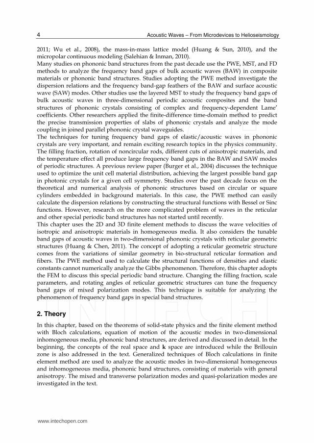
N1, N2, and N3 are integers. Figure 1 shows the primitive unit cell in two-dimensional real
space while the Fig. 2 shows the relationship between the real space and k space. A property
between the primitive lattice vectors and associated primitive reciprocal lattice vectors is
2i j ijπδ⋅ =b a , where ijδ is the kronecker symbol. Note that the associated primitive
reciprocal lattice vectors are constructed as k space from the concept of crystal diffraction.
2a
1a
1a
1a
2a
2a
I
II
III
Fig. 1. Primitive unit cell in real space
k space Real space
2b
1b
2a
1a
Fig. 2. Relationship between the real space and k space
We will find that, in following sections, the discrete translational symmetry of a phononic crystal allows us to classify the elastic/acoustic waves with a wave vector k. The
www.intechopen.com

Acoustic Waves – From Microdevices to Helioseismology
6
propagating modes can be written in “Bloch form,” consisting of a plane wave modulated by a function that shares the periodicity of the lattice (Joannopoulos et al., 1995):
.i ie e⋅ ⋅= = +k r k rk k kP (r) u (r) u (r R) (2)
The important feature of the Bloch states is that different values of k do not necessarily lead to different modes. It is clear that a mode with wave vector k and a mode with wave vector k+G are the same mode, where G is a reciprocal lattice vector. The wave vector k serves to specify the phase relationship between the various cells that are described by u. If k is
increased by G, then the phase between cells is increased by G⋅R, which we know is 2πn (n= l1N1+l2N2+ l3N3 is an integer) and not really a phase difference at all. So incrementing k by G results in the same physical mode. This means that we can restrict our attention to a finite zone in reciprocal space in which we cannot get from one part of the volume to another by adding any G. All values of k that lie outside of this zone, by definition, can be reached from within the zone by adding G, and are therefore redundant labels shown in Fig. 3. This zone is the so-called Brillouin zone.
k y
kx
k'K
G
πa
πa
-πa
-πa
G
Fig. 3. All values of k that lie outside of this zone, by definition, can be reached from within the zone by adding G
1
0
876
54
32
2 / aπ
1 Bril louin zonest
3 Brillouin zonerd
2 Br il louin zonend
Fig. 4. Brillouin zones in a square lattice
www.intechopen.com
Analysis of Acoustic Wave in Homogeneous and Inhomogeneous Media Using Finite Element Method
7
By the periodicity of the reciprocal lattice, any reciprocal lattice point which represents a wave vector k outside the first Brillouin zone can be found a corresponding point in the first Brillouin zone. Therefore, the wave vectors k can always be confined in the first Brillouin zone. In the square lattice, only the wave vectors k in the region of the first Brillouin zone between aπ− to aπ (the lattice constant is a) need to be considered. The Fig. 4 shows the
first, second, and third Brillouin zones. For more details, it is best to consult the first few chapters of a solid-state physics text, such as Kittel, 1996, or consult the appendix of popular photonic text like Joannopoulos et al. 1995 and Johnson & Joannopoulos, 2001, 2003.
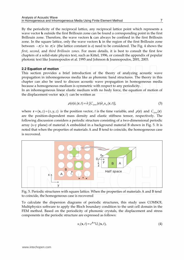
2.2 Equation of motion This section provides a brief introduction of the theory of analyzing acoustic wave propagation in inhomogeneous media like as phononic band structures. The theory in this chapter can also be used to discuss acoustic wave propagation in homogeneous media because a homogeneous medium is symmetric with respect to any periodicity. In an inhomogeneous linear elastic medium with no body force, the equation of motion of
the displacement vector ( , )tu r can be written as
( ) ( , ) [ ( ) ( , )],i j ijmn n mu t C u tρ = ∂ ∂r r r r (3)
where ( , ) ( , , )z x y z= =r x is the position vector, t is the time variable, and ( )ρ r and ( )ijmnC r
are the position-dependent mass density and elastic stiffness tensor, respectively. The
following discussion considers a periodic structure consisting of a two-dimensional periodic
array (x-y plane) of material A embedded in a background material B shown in Fig. 5. It is
noted that when the properties of materials A and B tend to coincide, the homogeneous case
is recovered.
x
y
AB
B Az
x
y0
Half spacer 0
a
Fig. 5. Periodic structures with square lattice. When the properties of materials A and B tend to coincide, the homogeneous case is recovered
To calculate the dispersion diagrams of periodic structures, this study uses COMSOL Multiphysics software to apply the Bloch boundary condition to the unit cell domain in the FEM method. Based on the periodicity of phononic crystals, the displacement and stress components in the periodic structure are expressed as follows:
( , ) ( , ),ii iu t e U t⋅= k xx x (4)
www.intechopen.com
Acoustic Waves – From Microdevices to Helioseismology
8
( , ) ( , ),iij ijt e T tσ ⋅= k xx x (5)
where 1 2( , )k k=k is the Bloch wave vector, and 1i = − ; ( , )iU tx and ( , )ijT tx are periodic
functions that satisfy the following relation (Tanaka et al., 2000):
( , ) ( , ),i iU t U t+ =x R x (6)
( , ) ( , ),ij ijT t T t+ =x R x (7)
where R is a lattice translation vector with components of 1R and 2R in the x and y
directions. The relationships between the original variables ( , )iu tx , ( , )ij tσ x , ( , )iu t+x R ,
and ( , )ij tσ +x R about the Bloch boundary conditions are characterized as:
( )( , ) ( , ) ( , ) ( , ),i i i ii i i iu t e U t e e U t e u t⋅ + ⋅ ⋅ ⋅+ = + = =k x R k R k x k Rx R x R x x (8)
( )( , ) ( , ) ( , ) ( , ).i i i iij ij ij ijt e T t e e T t e tσ σ⋅ + ⋅ ⋅ ⋅+ = + = =k x R k R k x k Rx R x R x x (9)
The Bloch calculations in this study record the variation of the displacements, stress fields, and eigen-frequencies as the wave vector increases. By using the FEM, the unit cell is meshed and divided into finite elements which connect by nodes, and is used to obtain the eigen-solutions and mechanical displacements. The types of finite elements used in this chapter are the default element types, Lagrange-quadratic, in COMSOL Multiphysics. In order to simulate the dispersion diagrams, the wave vectors are condensed inside the first Brillouin zone in the square lattice. According to the above theories, the results of dispersion relations in a band structure along the Γ − Χ − Μ − Γ are characterized and presented in the following sections.
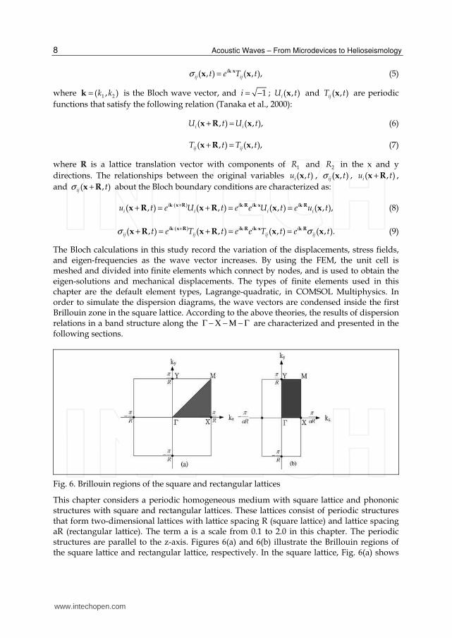
Fig. 6. Brillouin regions of the square and rectangular lattices
This chapter considers a periodic homogeneous medium with square lattice and phononic structures with square and rectangular lattices. These lattices consist of periodic structures that form two-dimensional lattices with lattice spacing R (square lattice) and lattice spacing aR (rectangular lattice). The term a is a scale from 0.1 to 2.0 in this chapter. The periodic structures are parallel to the z-axis. Figures 6(a) and 6(b) illustrate the Brillouin regions of the square lattice and rectangular lattice, respectively. In the square lattice, Fig. 6(a) shows
www.intechopen.com

Analysis of Acoustic Wave in Homogeneous and Inhomogeneous Media Using Finite Element Method
9
the irreducible part of the Brillouin zone, which is a triangle with vertexes Γ , Χ , and Μ . Similarly, Fig. 6(b) shows the irreducible part of the Brillouin zone of a rectangular lattice
due to the geometric anisotropy, which is a rectangle with vertexes Γ , Χ , Μ , and Y , and the same as discussing the material anisotropy (Wu et al., 2004). The finite element method divides a unit cell with a three-dimensional model into finite
elements connected by nodes. The FEM obtains the eigen-solutions and contours of a mode
shape. To simulate the dispersion diagrams, the wave vectors are condensed inside the first
Brillouin zone in the square and rectangular lattices. Using the theories above, the following
section presents the results of dispersion relations in a band structure for the Γ − Χ − Μ − Γ
square lattice or isotropic materials, and YΓ − Χ − Μ − − Γ rectangular lattice or anisotropic
materials. Note that the 2D FEM model calculates the dispersion relations of mixed
polarization modes, while the 3D FEM model describes the dispersion relations of mixed
and transverse polarization modes.
3. Acoustic wave in homogeneous media
It can be noted that a homogeneous medium is symmetric with respect to any periodicity,
and it can be shown that the results for an infinite homogeneous medium can be cast in the
form appropriate for a periodic medium. In this section, we introduce the mixed
polarization modes and transverse polarization modes in a homogeneous medium.
Displacement fields (polarizations) are also investigated and used to distinguish the
different modes in the dispersion relations. The aluminum and quartz are adopted for
examples and discussed in the section. The wave velocities of different propogating modes
are also observed and discussed.
3.1 Isotropic medium
In Fig. 5, when the properties of materials A and B tend to coincide, the homogeneous case
is recovered. Consider a periodic structure consisting of aluminum (Al) circular cylinders
embedded in a background material of Al forming a two-dimensional square lattice with
lattice spacing R. It means this is a homogeneous medium in a 3D FEM model. Figure 7
shows the dispersion relations along the boundaries of the irreducible part of the Brillouin
zone Γ − Χ − Μ − Γ . The vertical axis is the frequency (Hz) and the horizontal axis is the
reduced wave vector * /k kR π= . Here, k is the wave vector along the Brillouin zone. The
Young’s modulus E, Poisson’s ratio ν , and density ρ of the material Al utilized in this
example are E=70 GPa, ν =0.33, and ρ =2700 kg/m3.
As the elastic waves propagate along the x axis, the nonvanishing displacement fields of the
shear horizontal mode (SH), shear vertical mode (SV), and longitudinal mode (L) are uy, uz,
and ux respectively. It is noted that wave velocity , ,/ 2 *S L S Lc d dk R mω= = , so the slopes of
dispersion curves in the Γ − Χ section of Fig. 7 are exactly the straight lines and can be
explained as the wave velocities of shear (S) and longitudinal (L) modes. Here, mS,L are the
slopes of shear and longitudinal modes in Fig. 7. It is noted that the wave velocities of shear
horizontal mode and shear vertical mode are the same in an isotropic material. From the
results in Fig. 7, the wave velocities of shear and longitudinal modes are 3119 and 6174 m/s.
As we know, the wave velocities of shear and longitudinal modes in an isotropic material
can be obtain from
www.intechopen.com
Acoustic Waves – From Microdevices to Helioseismology
10
1
3122 / ,2(1 )
S
Ec m s
ρ ν= =
+ (10)
(1 )
6031 / .(1 )(1 2 )
L
Ec m s
ν
ρ ν ν
−= =
+ − (11)
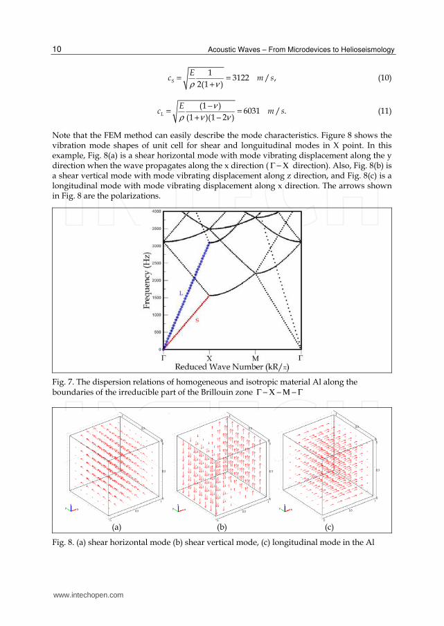
Note that the FEM method can easily describe the mode characteristics. Figure 8 shows the vibration mode shapes of unit cell for shear and longuitudinal modes in X point. In this example, Fig. 8(a) is a shear horizontal mode with mode vibrating displacement along the y direction when the wave propagates along the x direction ( Γ − Χ direction). Also, Fig. 8(b) is a shear vertical mode with mode vibrating displacement along z direction, and Fig. 8(c) is a longitudinal mode with mode vibrating displacement along x direction. The arrows shown in Fig. 8 are the polarizations.
Fig. 7. The dispersion relations of homogeneous and isotropic material Al along the boundaries of the irreducible part of the Brillouin zone Γ − Χ − Μ − Γ
(a) (b) (c)
Fig. 8. (a) shear horizontal mode (b) shear vertical mode, (c) longitudinal mode in the Al
www.intechopen.com

Analysis of Acoustic Wave in Homogeneous and Inhomogeneous Media Using Finite Element Method
11
3.2 Anisotropic medium
Similarly, the method in this chapter is used to discuss the wave velocities of acoustic modes
in an anisotropic material. Consider a periodic structure consisting of quartz circular
cylinders embedded in a background material of quartz forming a two-dimensional square
lattice with lattice spacing R. This is also a homogeneous medium. The quartz is a
piezoelectric and anisotropic material. The density ρ =2651 kg/m3. The elastic constants,
piezoelectric constants, and relative permittivity of quartz utilized in this example are
shown in Tables 1-3. The piezoelectric material, quartz, is a complete structural-electrical
material, and thus all piezoelectric material properties were defined and entered into the
FEM model. Figure 9 shows the dispersion relations along the boundaries of the irreducible
part of the Brillouin zone YΓ − Χ − Μ − − Γ due to the material anisotropy. In the
calculations, the x-y plane is parallel to the (001) plane and the x axis is along the [100]
direction of quartz. The vertical axis is the frequency in Hz unit and the horizontal axis is the
reduced wave vector.
86.7362 6.98527 11.9104 17.9081 0 0
6.98527 86.7362 11.9104 -17.9081 0 0
11.9104 11.9104 107.194 0 0 0
17.9081 -17.9081 0 57.9428 0 0
0 0 0 0 57.9492 17.9224
0 0 0 0 17.9224 39.9073
Table 1. The elastic constants of quartz in GPa unit
-0.19543 0.19543 0 -0.1212 0 0
0 0 0 0 0.12127 0.19558
0 0 0 0 0 0
Table 2. The piezoelectric constants of quartz in C/m2 unit
4.4093 0 0
0 4.4092 0
0 0 4.68
Table 3. The relative permittivity of quartz
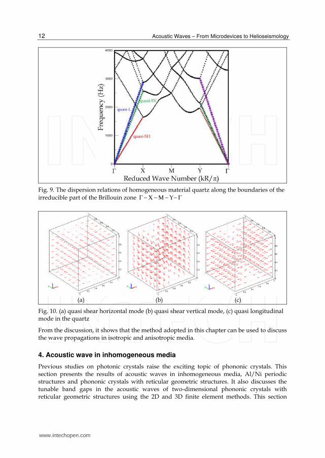
Shown in Γ − Χ section of Fig. 9, the cross symbols represent the quasi shear horizontal
(quasi-SH) mode. The square symbols represent the quasi shear vertical (quasi-SV) mode
and the open circle symbols represent the quasi longitudinal (quasi-L) mode. The wave
velocities of quasi-SH, quasi-SV, and quasi-L modes along x axis are 3306, 5116, and 5741
m/s. Similarly, The wave velocities of quasi-SH, quasi-SV, and quasi-L modes along y axis
( YΓ − section) are 3922, 4311, and 6009 m/s respectively.
Figure 10 also shows the vibration mode shapes of unit cell for quasi-SH, quasi-SV, and
quasi-L modes in X point. The arrows shown in Fig. 10 are the polarizations. In this
example, the quasi-longitudinal and quasi-transverse waves are almost indistinguishable
from the truly longitudinal and truly transverse waves of Fig. 8.
www.intechopen.com
Acoustic Waves – From Microdevices to Helioseismology
12
Fig. 9. The dispersion relations of homogeneous material quartz along the boundaries of the
irreducible part of the Brillouin zone YΓ − Χ − Μ − − Γ
(a) (b) (c)
Fig. 10. (a) quasi shear horizontal mode (b) quasi shear vertical mode, (c) quasi longitudinal mode in the quartz
From the discussion, it shows that the method adopted in this chapter can be used to discuss the wave propagations in isotropic and anisotropic media.
4. Acoustic wave in inhomogeneous media
Previous studies on photonic crystals raise the exciting topic of phononic crystals. This section presents the results of acoustic waves in inhomogeneous media, Al/Ni periodic structures and phononic crystals with reticular geometric structures. It also discusses the tunable band gaps in the acoustic waves of two-dimensional phononic crystals with reticular geometric structures using the 2D and 3D finite element methods. This section
www.intechopen.com
Analysis of Acoustic Wave in Homogeneous and Inhomogeneous Media Using Finite Element Method
13
calculates and discusses the band gap variations of the bulk modes due to different sizes of reticular geometric structures. Results show that adjusting the orientation of the reticular geometric structures can increase or decrease the total elastic band gaps for mixed polarization modes.
4.1 Periodic structure with two media
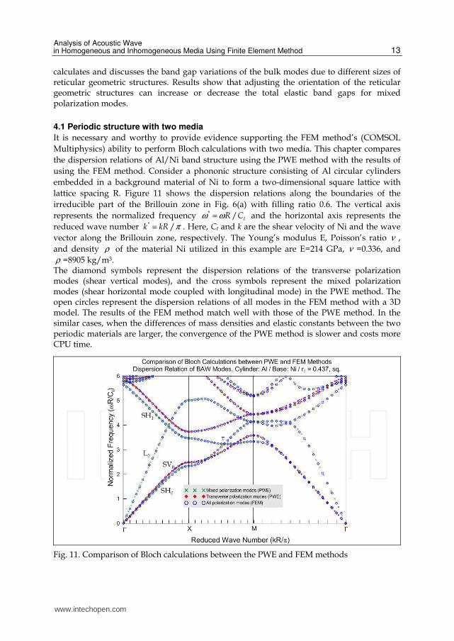
It is necessary and worthy to provide evidence supporting the FEM method’s (COMSOL
Multiphysics) ability to perform Bloch calculations with two media. This chapter compares
the dispersion relations of Al/Ni band structure using the PWE method with the results of
using the FEM method. Consider a phononic structure consisting of Al circular cylinders
embedded in a background material of Ni to form a two-dimensional square lattice with
lattice spacing R. Figure 11 shows the dispersion relations along the boundaries of the
irreducible part of the Brillouin zone in Fig. 6(a) with filling ratio 0.6. The vertical axis
represents the normalized frequency * / tR Cω ω= and the horizontal axis represents the
reduced wave number * /k kR π= . Here, Ct and k are the shear velocity of Ni and the wave
vector along the Brillouin zone, respectively. The Young’s modulus E, Poisson’s ratio ν ,
and density ρ of the material Ni utilized in this example are E=214 GPa, ν =0.336, and
ρ =8905 kg/m3. The diamond symbols represent the dispersion relations of the transverse polarization modes (shear vertical modes), and the cross symbols represent the mixed polarization modes (shear horizontal mode coupled with longitudinal mode) in the PWE method. The open circles represent the dispersion relations of all modes in the FEM method with a 3D model. The results of the FEM method match well with those of the PWE method. In the similar cases, when the differences of mass densities and elastic constants between the two periodic materials are larger, the convergence of the PWE method is slower and costs more CPU time.
Fig. 11. Comparison of Bloch calculations between the PWE and FEM methods
www.intechopen.com

Acoustic Waves – From Microdevices to Helioseismology
14
As the elastic waves propagate along the x axis, the nonvanishing displacement fields of the shear horizontal mode, shear vertical mode, and longitudinal mode are uy, uz, and ux respectively. For the sequence modes appear, the modes are always the same. When representing the whole wave vector space by the first Brillouin zone alone, they appear as further branches from higher Brillouin zones. In this example, the phase velocities of the SV0 mode (diamond symbols) are larger than those of the SH0 mode. The boundary of the Brillouin zone X-M of Fig. 11 represents the dispersion of the bulk waves with propagating direction varied 0 deg~ 45 deg counterclockwise away from the x direction.
4.2 Periodic structure with single medium Figure 12(a) depicts a two-dimensional phononic crystal with the reticular geometric structures of square lattice. These reticular structures are parallel to the z-axis. In a perfect two-dimensional phononic crystal, the periodic structure is constant in the z direction and the size of the structure is infinite in the x and y directions. To analyze the dispersion relations of all bulk acoustic modes in this band structure, the FEM should consider the 3D model in Fig. 12(c). The dimensions of the unit cell in Fig. 12(a) are c=d=0.8R and R=h=1 in the calculations.
Fig. 12. (a) square lattice with lattice spacing R and (b) rectangular lattice with lattice spacing aR along x-axis and R along y-axis, (c) a unit cell with reticular structures in a 3D FEM model
The material of the reticular structures in the unit cell in this chapter is aluminum. Figure 12(c) shows a diagram of the unit square lattice in a 3D FEM model. The periodicity of phononic crystals along the z direction is used to calculate the dispersion relations of the mixed and transverse polarization modes. The types of finite elements used for the 2D and 3D cases are the default element types, Lagrange-Quadratic, in COMSOL Multiphysics. Figure 13 shows the dispersion relations of the mixed and transverse polarization modes along the boundaries of the irreducible part of the Brillouin zone in Fig. 6(b) with the scales R=h=1, c=0.8, and a=1.2. The horizontal axis represents the reduced wave number along
YΓ − Χ − Μ − − Γ and the vertical axis represents the frequency (Hz). Note that this band structure shows no full band gap of the mixed and transverse polarization modes. Adopting the 2D FEM model to discuss the mixed polarization modes in this kind of band structure shows that there is only one full frequency band gap in Fig. 13, located at 3311 ~ 3400 Hz. Figure 13 compares the 3D and 2D FEM models. Open circles represent the dispersion
www.intechopen.com

Analysis of Acoustic Wave in Homogeneous and Inhomogeneous Media Using Finite Element Method
15
relations of mixed polarization modes in the 2D FEM model, while solid circles represent the results of all bulk modes in the 3D FEM model. Figure 14 shows the eigenmode shapes with 4×4 supercell of total displacements for M1 and M2 modes indicated in Fig. 13. These figures clearly show the phenomena of wave localizations in this reticular geometric structure. Note that the FEM method can easily describe the mode characteristics. In this chapter, M1 is a shear horizontal mode with mode vibrating displacement along the y direction when the wave propagates along the x direction ( Γ − Χ direction). Also, M2 is a shear vertical mode with mode vibrating displacement along z direction, and it does not couple with the mixed polarization modes.
Fig. 13. The dispersion relations of the mixed and transverse polarization modes along the boundaries of the irreducible part of the Brillouin zone with the scales R=h=1, c=0.8, and a=1.2
M1 M2
Fig. 14. The eigenmode shapes with 4×4 supercell of total displacements for M1 and M2 modes indicated in Fig. 13
www.intechopen.com
Acoustic Waves – From Microdevices to Helioseismology
16
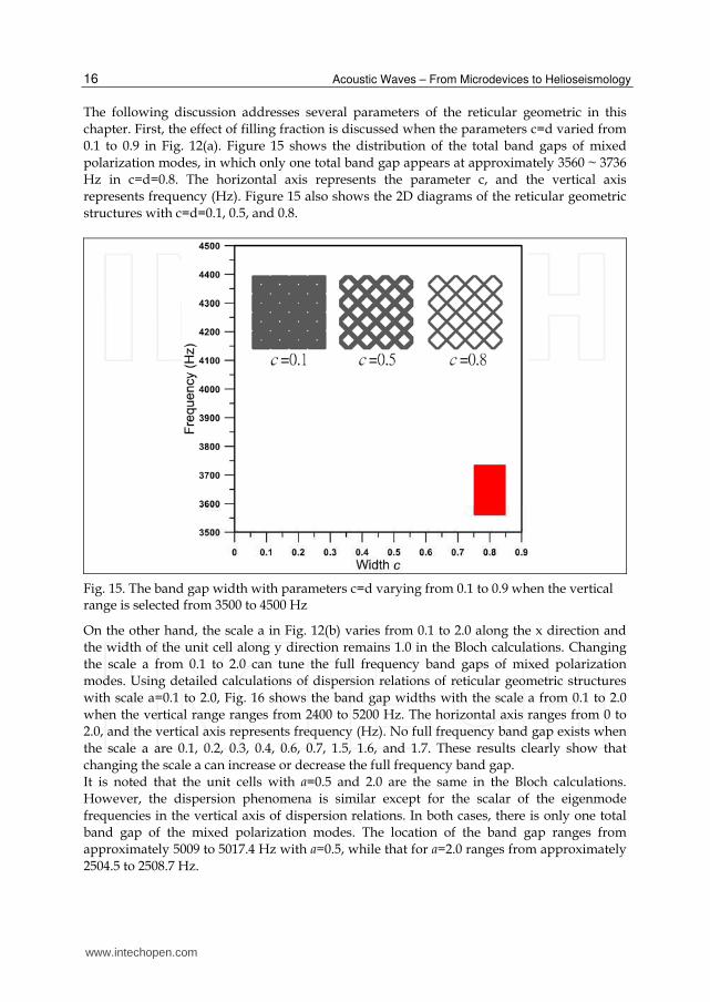
The following discussion addresses several parameters of the reticular geometric in this
chapter. First, the effect of filling fraction is discussed when the parameters c=d varied from
0.1 to 0.9 in Fig. 12(a). Figure 15 shows the distribution of the total band gaps of mixed
polarization modes, in which only one total band gap appears at approximately 3560 ~ 3736
Hz in c=d=0.8. The horizontal axis represents the parameter c, and the vertical axis
represents frequency (Hz). Figure 15 also shows the 2D diagrams of the reticular geometric
structures with c=d=0.1, 0.5, and 0.8.
Fig. 15. The band gap width with parameters c=d varying from 0.1 to 0.9 when the vertical range is selected from 3500 to 4500 Hz
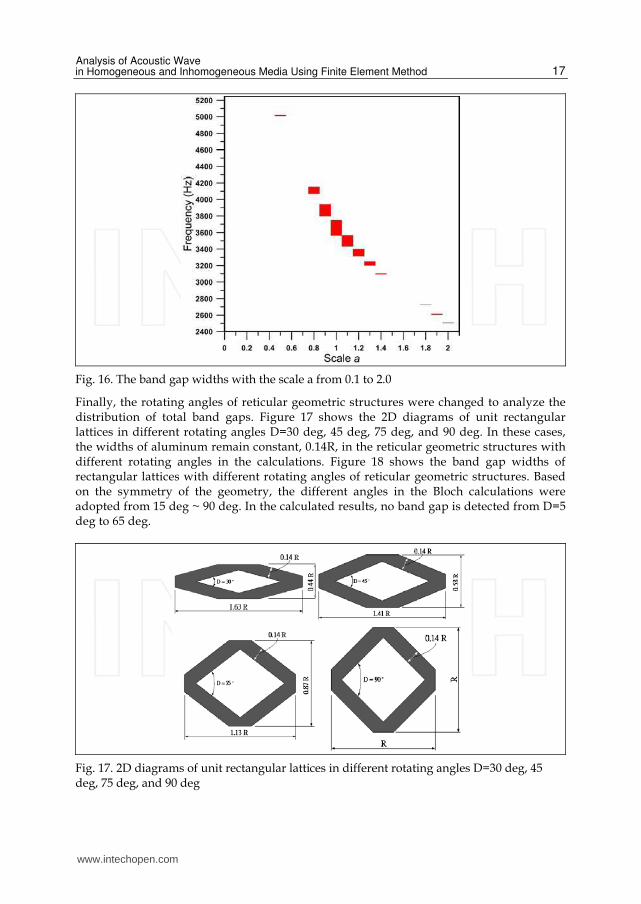
On the other hand, the scale a in Fig. 12(b) varies from 0.1 to 2.0 along the x direction and
the width of the unit cell along y direction remains 1.0 in the Bloch calculations. Changing
the scale a from 0.1 to 2.0 can tune the full frequency band gaps of mixed polarization
modes. Using detailed calculations of dispersion relations of reticular geometric structures
with scale a=0.1 to 2.0, Fig. 16 shows the band gap widths with the scale a from 0.1 to 2.0
when the vertical range ranges from 2400 to 5200 Hz. The horizontal axis ranges from 0 to
2.0, and the vertical axis represents frequency (Hz). No full frequency band gap exists when
the scale a are 0.1, 0.2, 0.3, 0.4, 0.6, 0.7, 1.5, 1.6, and 1.7. These results clearly show that
changing the scale a can increase or decrease the full frequency band gap.
It is noted that the unit cells with a=0.5 and 2.0 are the same in the Bloch calculations.
However, the dispersion phenomena is similar except for the scalar of the eigenmode
frequencies in the vertical axis of dispersion relations. In both cases, there is only one total
band gap of the mixed polarization modes. The location of the band gap ranges from
approximately 5009 to 5017.4 Hz with a=0.5, while that for a=2.0 ranges from approximately
2504.5 to 2508.7 Hz.
www.intechopen.com
Analysis of Acoustic Wave in Homogeneous and Inhomogeneous Media Using Finite Element Method
17
Fig. 16. The band gap widths with the scale a from 0.1 to 2.0
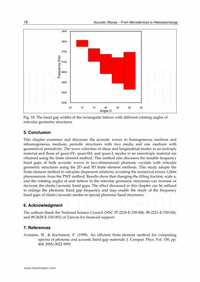
Finally, the rotating angles of reticular geometric structures were changed to analyze the distribution of total band gaps. Figure 17 shows the 2D diagrams of unit rectangular lattices in different rotating angles D=30 deg, 45 deg, 75 deg, and 90 deg. In these cases, the widths of aluminum remain constant, 0.14R, in the reticular geometric structures with different rotating angles in the calculations. Figure 18 shows the band gap widths of rectangular lattices with different rotating angles of reticular geometric structures. Based on the symmetry of the geometry, the different angles in the Bloch calculations were adopted from 15 deg ~ 90 deg. In the calculated results, no band gap is detected from D=5 deg to 65 deg.
Fig. 17. 2D diagrams of unit rectangular lattices in different rotating angles D=30 deg, 45 deg, 75 deg, and 90 deg
www.intechopen.com
Acoustic Waves – From Microdevices to Helioseismology
18
Fig. 18. The band gap widths of the rectangular lattices with different rotating angles of reticular geometric structures
5. Conclusion
This chapter examines and discusses the acoustic waves in homogeneous medium and inhomogeneous medium, periodic structures with two media and one medium with geometrical periodicity. The wave velocities of shear and longitudinal modes in an isotropic material and those of quasi-SV, quasi-SH, and quasi-L modes in an anisotropic material are obtained using the finite element method. This method also discusses the tunable frequency band gaps of bulk acoustic waves in two-dimensional phononic crystals with reticular geometric structures using the 2D and 3D finite element methods. This study adopts the finite element method to calculate dispersion relations, avoiding the numerical errors, Gibbs phenomenon, from the PWE method. Results show that changing the filling fraction, scale a, and the rotating angles of unit lattices in the reticular geometric structures can increase or decrease the elastic/acoustic band gaps. The effect discussed in this chapter can be utilized to enlarge the phononic band gap frequency and may enable the study of the frequency band gaps of elastic/acoustic modes in special phononic band structures.
6. Acknowledgment
The authors thank the National Science Council (NSC 97-2218-E-150-006, 98-2221-E-150-026, and 99-2628-E-150-001) of Taiwan for financial support.
7. References
Axmann, W. & Kuchment, P. (1999). An efficient finite element method for computing spectra of photonic and acoustic band-gap materials. J. Comput. Phys. Vol. 150, pp. 468, ISSN 0021-9991
www.intechopen.com
Analysis of Acoustic Wave in Homogeneous and Inhomogeneous Media Using Finite Element Method
19
Burger, M. S., Osher, J., & Yablonovitch, E. (2004). Inverse Problem Techniques for the Design of Photonic Crystals. IEICE Trans. Electron, E87C, 258-265.
Checoury, X. & Lourtioz, J. M. (2006). Wavelet method for computing band diagrams of 2D photonic crystals. Optics Communications Vol. 59, pp. 360, ISSN 0030-4018
Chiang, P. J., Yu, C. P., & Chang, H. C. (2007). Analysis of two-dimensional photonic crystals using a multidomain pseudospectral method. Phys. Rev. E Vol. 75, pp. 026703, ISSN 1539-3755
Dobson, D. C. (1999). An efficient method for band structure calculations in 2D photonic crystals. J. Comput. Phys. Vol. 149, pp. 363, ISSN 0021-9991
Garica-Pablos, D., Sigalas, M., Montero de Espinosa, F. R., Torres, M., Kafesaki, M., and Garcia, N. (2000). Theory and Experiments on Elastic Band gaps. Phys. Rev. Lett. Vol. 84, pp. 4349, ISSN 0031-9007
Huang, G. L. & Sun, C. T. (2010). Band Gaps in a Multiresonator Acoustic Metamaterial. ASME J. Vib. Acoust. Vol. 132, pp. 031003. ISSN 1048-9002
Huang, Z. G. & Chen, Z. Y. (2011). Acoustic Waves in Two-dimensional Phononic Crystals with Reticular Geometric Structures. ASME J. Vib. Acoust. Vol. 133(3), pp.031011, ISSN 1048-9002
Huang, Z. G. & Wu, T.-T. (2005). Temperature effects on bandgaps of surface and bulk acoustic waves in two-dimensional phononic crystals. IEEE Trans. Ultrason. Ferroelectr. Freq. Control Vol. 52, pp. 365, ISSN 0885-3010
Hussein, M. I. (2009). Reduced Bloch mode expansion for periodic media band structure calculations. Proceedings of the Royal Society A Vol. 465, pp. 2825-2848, ISSN 1364–5021
Joannopoulos, J. D., Meade, R. D. & Winn, J. N. (1995) . Photonic Crystals: Molding the flow of light, ISBN: 978-0691124568, Princeton University Press, Princeton, NJ.
Johnson, S. G. & Joannopoulos, J. D. (2001). Block-iterative frequency-domain methods for Maxwell’s equations in a planewave basis. Optics Express Vol. 8, pp. 173, ISSN 1094-4087
Johnson, S. G. & Joannopoulos, J. D. (2003). PHOTONIC CRYSTALS: The road from theory to practice, ISBN 978-0792376095, Kluwer academic publishers, Boston.
Jun, S., Cho, Y. S., & Im, S. (2003). Moving least-square method for the band-structure calculation of 2D photonic crystals. Optics Express Vol. 11, pp. 541, ISSN 1094-4087
Kafesaki, M. & Economou, E. N. (1999). Multiple-scattering theory for three-dimensional periodic acoustic composites. Phys. Rev. B Vol. 60, pp. 11993, ISSN 1098-0121
Kittel, C. (1996). Introduction to Solid State Physics, ISBN 978-0-471-41526-8, 7th ed., John Wiley & Sons. Inc.
Kushwaha, M. S., Halevi, P., Dobrzynski, L. & Djafari-Rouhani, B. (1993). Acoustic Band Structure of Periodic Elastic Composites. Phys. Rev. Lett. Vol. 71, pp. 2022, ISSN 0031-9007
Laude, V., Wilm, M., Benchabane, S., Khelif, A. (2005). Full band gap for surface acoustic waves in a piezoelectric phononic crystal. Phys. Rev. E Vol. 71, pp. 036607, ISSN 1539-3755
Leung, K. M. & Liu, Y. F. (1990). Full vector wave calculation of photonic band structures in face-centered-cubic dielectric media. Phys. Rev. Lett. Vol. 65, pp. 2646, ISSN 0031-9007
www.intechopen.com
Acoustic Waves – From Microdevices to Helioseismology
20
Leung, K. M. & Qiu, Y. (1993). Multiple-scattering calculation of the two-dimensional photonic band structure. Phys. Rev. B Vol. 48, pp. 7767, ISSN 1098-0121
Moreno, E., Erni, D., & Hafner, C. (2002). Band structure computations of metallic photonic crystals with the multiple multipole method. Phys. Rev. B Vol. 65, pp. 155120, ISSN 1098-0121
Pendry, J. B. & MacKinnon, A. (1992). Calculation of photon dispersion relations. Phys. Rev. Lett. Vol. 69, pp. 2772, ISSN 0031-9007
Psarobas, I. E. & Stefanou, N. (2000). Scattering of elastic waves by periodic arrays of spherical bodies. Phys. Rev. B Vol. 62, pp. 278, ISSN 1098-0121
Salehian, A. & Inman, D. J. (2010). Micropolar Continuous Modeling and Frequency Response Validation of a Lattice Structure. ASME J. Vib. Acoust. Vol. 132, pp.011010, ISSN 1048-9002
Sun, J. H. & Wu, T.-T. (2005). Analyses of mode coupling in joined parallel phononic crystal waveguides. Phys. Rev. B Vol. 71, pp. 174303, ISSN 1098-0121
Tanaka, Y. & Tamura, S. (1998). Surface acoustic waves in two-dimensional periodic elastic structures. Phys. Rev. B Vol. 58, pp. 7958, ISSN 1098-0121
Tanaka, Y., Tomoyasu, Y., & Tamura, S. I. (2000). Band structure of acoustic waves in phononic lattices: Two-dimensional composites with large acoustic mismatch. Phys. Rev. B Vol.62, no. 11, 7387–7392.
Wang, X., Zhang, X. G., Yu, Q. & Harmon, B. N. (1993). Multiple-scattering theory for electromagnetic waves. Phys. Rev. B Vol. 47, pp. 4161, ISSN 1098-0121
Wu, T.-T. & Huang, Z. G. (2004). Level repulsion of bulk acoustic waves in composite materials. Phys. Rev. B Vol. 70, pp. 214304, ISSN 1098-0121
Wu, T.-T., Huang, Z. G., & Lin, S. (2004). Surface and bulk acoustic waves in two-dimensional phononic crystals consisting of materials with general anisotropy. Phys. Rev. B Vol. 69, pp. 094301, ISSN 1098-0121
Wu, T.-T., Huang, Z. G., Tsai, T. C. & Wu, T. C. (2008). Evidence of complete band gap and resonances in a plate with periodic stubbed surface. Applied Physics Letters Vol. 93, pp. 111902, ISSN 0003-6951
Yan, Z. Z. & Wang, Y. S. (2006). Wavelet-based method for calculating elastic band gaps of two-dimensional phononic crystals. Phys. Rev. B Vol. 74, pp. 224303, ISSN 1098-0121
Yang, H. Y. D. (1996). Finite difference analysis of 2-D photonic crystals. IEEE Trans. Microwave Theory Tech. Vol. 44, pp. 2688, ISSN 0018-9480
www.intechopen.com
Acoustic Waves - From Microdevices to HelioseismologyEdited by Prof. Marco G. Beghi
ISBN 978-953-307-572-3Hard cover, 652 pagesPublisher InTechPublished online 14, November, 2011Published in print edition November, 2011
InTech EuropeUniversity Campus STeP Ri Slavka Krautzeka 83/A 51000 Rijeka, Croatia Phone: +385 (51) 770 447 Fax: +385 (51) 686 166www.intechopen.com
InTech ChinaUnit 405, Office Block, Hotel Equatorial Shanghai No.65, Yan An Road (West), Shanghai, 200040, China
Phone: +86-21-62489820 Fax: +86-21-62489821
The concept of acoustic wave is a pervasive one, which emerges in any type of medium, from solids toplasmas, at length and time scales ranging from sub-micrometric layers in microdevices to seismic waves inthe Sun's interior. This book presents several aspects of the active research ongoing in this field. Theoreticalefforts are leading to a deeper understanding of phenomena, also in complicated environments like the solarsurface boundary. Acoustic waves are a flexible probe to investigate the properties of very different systems,from thin inorganic layers to ripening cheese to biological systems. Acoustic waves are also a tool tomanipulate matter, from the delicate evaporation of biomolecules to be analysed, to the phase transitionsinduced by intense shock waves. And a whole class of widespread microdevices, including filters and sensors,is based on the behaviour of acoustic waves propagating in thin layers. The search for better performances isdriving to new materials for these devices, and to more refined tools for their analysis.
How to referenceIn order to correctly reference this scholarly work, feel free to copy and paste the following:
Zi-Gui Huang (2011). Analysis of Acoustic Wave in Homogeneous and Inhomogeneous Media Using FiniteElement Method, Acoustic Waves - From Microdevices to Helioseismology, Prof. Marco G. Beghi (Ed.), ISBN:978-953-307-572-3, InTech, Available from: http://www.intechopen.com/books/acoustic-waves-from-microdevices-to-helioseismology/analysis-of-acoustic-wave-in-homogeneous-and-inhomogeneous-media-using-finite-element-method


![Local Wave Number Model for Inhomogeneous Two-Fluid Mixing · ow, with Unstably Strati ed Homogeneous Turbulence (USHT) [22], and shear-driven and buoyancy-driven turbulent ows [19]](https://img.pdfslide.net/doc/110x75/60aa226afcf02805185c46e7/local-wave-number-model-for-inhomogeneous-two-fluid-mixing-ow-with-unstably-strati.jpg)