Embed Size (px)
Citation preview

This article has been accepted for inclusion in a future issue of this journal. Content is final as presented, with the exception of pagination.
IEEE TRANSACTIONS ON POWER DELIVERY 1
Analysis of Active Power Control for VSC–HVDCWenyuan Wang, Student Member, IEEE, Antony Beddard, Student Member, IEEE,
Mike Barnes, Senior Member, IEEE, and Ognjen Marjanovic, Member, IEEE
Abstract—This paper presents a comprehensive analysis of thelimitations and the key dynamics of closed-loop active powercontrol systems for voltage-source converter (VSC) HVDC,regarding stability, performance, and robustness. Detailed dy-namic models are derived and the controllability and robustnessissues for VSC active power control are identified. Limitationsimposed by ac system strength, converter operating point, andcurrent control design on the stability and performance of thetwo leading active power control principles are addressed, usingfrequency-response analysis and time-domain simulations. Thedynamic interactions between the active power control design andthe dc voltage droop control are examined. The simulations areperformed using average-value VSC models and a high-fidelitymodular multilevel converter model. Impacts of the active powercontrol design on dynamic behaviors of multiterminal dc (MTDC)systems are investigated using a four-terminal model. This paperprovides a systematic study on the key stability and performanceissues associated with the active power control. Furthermore, themethodology offers a framework for the analysis of more complexactive power and dc voltage droop controllers for future MTDCsystems.
Index Terms—Active power control, droop control, mod-ular multilevel converter (MMC), multiterminal dc (MTDC),voltage–source converter (VSC) HVDC.
I. INTRODUCTION
V OLTAGE-SOURCE converter (VSC) HVDC is the mostcompetitive technology to connect remotely located off-
shore wind farms. From the fastest level down, a typical cas-caded VSC-MTDC control system can be organized as: con-verter ac voltage control, converter current and power control,dc voltage droop control, station secondary control, and super-visory control. Active power control, which interacts with theinner converter current control and the outer voltage droop con-trol, impacts the ac and dc system and is paramount in the cas-caded control system. However, systematic analysis and con-troller design guidelines for the active power control systemhave not been established.
Manuscript received June 27, 2013; revised December 23, 2013, February 13,2014, and March 25, 2014; accepted April 29, 2014. This work was supportedin part by the National Grid, in part by the Engineering and Physical SciencesResearch Council (EPSRC), and in part by The University of Manchester. Paperno. TPWRD-00731-2013.The authors are with the School of Electrical and Electronic Engi-
neering, The University of Manchester, Manchester, M13 9PL, U.K. (e-mail:[email protected]; [email protected]; [email protected]; [email protected]).Color versions of one or more of the figures in this paper are available online
at http://ieeexplore.ieee.org.Digital Object Identifier 10.1109/TPWRD.2014.2322498
Fig. 1. Active power controllers employing vector current control. (a) Voltagedisturbance. (b) Power feedback. (c) rotating frame.
Most of the existing literature suggests that the active powercontrol is based upon direct control or vector current control.In the direct control discussed in [1] and [2], real and reactivepower are regulated using the ac voltage angle and magnitude.However, this type of control may not be practical since it doesnot have current limit capability and its bandwidth is limited byvarious ac resonance frequencies [2]. Thus, power-angle controlis not considered here. Vector control manipulates the ac currentin a rotating reference frame to achieve desired power flows. Adegree of current protection can be provided and a bandwidththat is much higher than grid frequency can be employed. Ac-tive power control based on vector current control can be furthercategorized into voltage disturbance control [3]–[9] (in effect, atype of feedforward control) and power feedback (FB) control[2], [10], [11] shown in Fig. 1. For the voltage disturbance feed-forward (FF) control, the current setpoint is directly calculatedfrom the power reference and transformed voltage.However, the stability, performance, and robustness of these
key active power control principles have not been assessedusing detailed analytical models. The limitations imposed bythe converter plant model and the controller structure have notbeen examined, which often leads to ac system strength and thefast current loop dynamics to be neglected. This paper providesa framework to tackle these more complex problems.Control of dc voltage in practical multiterminal systems is
likely to be based on distributed control, such as dc voltage
0885-8977 © 2014 IEEE. Personal use is permitted, but republication/redistribution requires IEEE permission.See http://www.ieee.org/publications_standards/publications/rights/index.html for more information.

This article has been accepted for inclusion in a future issue of this journal. Content is final as presented, with the exception of pagination.
2 IEEE TRANSACTIONS ON POWER DELIVERY
droop control [4]–[6], [10], [11], to allow multiple convertersto regulate the dc voltage simultaneously. In the droop control,dc voltage is regulated by modifying the converter active powerreferences in proportion to dc voltage deviations. The interac-tions between these two closely linked control systems, how-ever, have not been addressed in prior literature. In this paper,analytical models for droop control with detailed representationof power control loops are derived to enable such issues to beinvestigated using a frequency-response approach.This paper aims to comprehensively analyze closed-loop be-
haviors of active power control for VSC–HVDC systems, toprovide insight into the key limitations imposed by the VSCplant model and its control designs, and to offer a frameworkfor the analysis of the dynamics associated with power controlloops for future research. In order to perform such analysis, inSection II, mathematical models are derived for the plant andclosed-loop systems of the active power control as well as outerdc voltage droop control. Based on linearized analytical models,frequency-domain tools are then readily used to fully under-stand the impact that a particular controller has on the closed-loop performance and robustness, with the associated resultsshown in Section III, along with the verifications by simula-tion results generated by a range of average-value VSC models.In Section IV, the active power control strategies are furtherevaluated utilizing a high-fidelity point-to-point MMC-HVDCmodel. Finally, the effect of using the active power control struc-tures on the performance of the overall control system for mul-titerminal systems is analyzed using a four-terminal model inSection V.
II. TWO TYPES OF CONTROLLERS
The schematic diagram of the active power control and thevector current control is illustrated in Fig. 1. The inner currentcontrol is implemented in a -coordinate system. The phase-locked loop (PLL), which provides the reference angle of thetransform, normally enables the -axis to be aligned with the
voltage vector at the point of common coupling (PCC) in orderto achieve independent control of real and reactive power [12].A feedforward current term is used to reduce the cross couplingeffect between the -axis and -axis current control loops. Afeedforward voltage term is employed to compensate the gridvoltage disturbance.The fast-responding feedforward power controller assumes
that the PLL angle always aligns with the PCC voltage. Thisopen-loop controller, shown in Fig. 1(a), is based on system in-version. Existing literature assumes the converter ac current haslittle impact on the system voltage ; thus, this power controlloop would have very similar dynamics as those of the currentloop. However, this assumption may not be valid for a relativelyweak ac system. In addition, the steady-state error may not befully avoided for this feedforward design.For the feedback controller shown in Fig. 1(b), fast active
power regulation could not be achieved without a sufficientlyhigh-bandwidth current loop. Unlike the FF strategy, unknowndisturbances will have less of an effect on the control perfor-mance, and more accurate regulation of active power can beachieved.
A. More Detailed Current Loop
The plant model of the current loop is established ac-cording to the following equations:
(1)
(2)
where and represent the converter ac terminal voltageand the PCC bus voltage, respectively, in the reference frame,shown in Fig. 1. For PWM, two/three-level converters andrepresent the aggregated impedance of the converter reactor andtransformer.While forMMCs, and represent the equivalentimpedance of the arm reactor and the converter transformer, asshown
(3)
Since scaling could greatly simplify the model analysis, per-unit values will be used in all of the control system equations inthis paper. With the time retained in real values, the base valuesshown in (4) are employed
(4)
Since the generator dynamics are much slower than the fre-quency range of interest in this paper, the ac network is sim-plified and modeled using a voltage source in series with animpedance. The per-unit source impedance can be related to theshort-circuit ratio (SCR) as
(5)
With and , the difference betweenthe -axis converter voltage and the -component sourcevoltage can be modeled as (6), which is in the similar formof (1)
(6)
For the derivations in this section, and are considered tobe disturbances of the current control. The converter voltagereference is the input to be manipulated.Combining (1) and (6), the -axis voltage at the PCC can be
written as
(7)
By combining (6) and (7), the following transfer functionscan be derived for and :
(8)
(9)

This article has been accepted for inclusion in a future issue of this journal. Content is final as presented, with the exception of pagination.
WANG et al.: ANALYSIS OF ACTIVE POWER CONTROL FOR VSC–HVDC 3
Fig. 2. Model of the -axis current loop (considering dynamics of .
The plant model of the -axis current control is formed from(1) and (9), shown in Fig. 2. The disturbances and the associatedtransfer functions are illustrated.
(10)
(11)
The converter ac voltage control is approximated using afirst-order system with time constant . In this analysis, idealmeasurements are assumed for the feedforward terms and .
B. Feedforward and Feedback Power Control
By employing per-unit values, the factor of 1.5 can be elimi-nated in the representation of the instantaneous power injectioninto the ac system
(12)
Assuming the synchronization is maintained by the PLL, thefeedforward power controller can be linearized as
(13)
Substituting (7) for in (12), the active power can be foundas (14), assuming to be 0. Equation (14) can be linearized andsimplified to the expression shown in (16), considering (15),which is derived based on (1) and (6). The general conditionis that is assumed. The subscript “o” refers to theoperating point (OP).
(14)
(15)
(16)
Fig. 3. Linearized model of the feedforward power control.
Fig. 4. Linearized model of the feedback power control.
Substituting in (16) with (8), the plant models of theconverter voltage and the output disturbances are obtained as
(17)
(18)
By incorporating the current loop model, the block diagramof the feedforward loop is then structured as shown in Fig. 3.A key insight revealed in Fig. 3 is that for a nonideal ac gridmodel, the PCC voltage is inherently affected by the currentloop dynamics and, therefore, indirect feedback is effectivelyformed between the VSC -axis voltage and the current ref-erence . An inverter operation with introduces neg-ative feedback while a rectifier operation with leadsto undesired positive feedback. Hence, the converter operatingpoint could have a profound impact on the stability of the FFactive power control.The feedback controller employs a typical cascaded structure,
shown in Fig. 4, with the outer PI controller typically designedto enable the secondary loop to be at least 4 times slower thanthe inner loop [13]. However, higher order controllers can bereadily incorporated into the methodology and the closed-loopsystem models presented here.The closed-loop transfer function that describes the reference
tracking of the FF control is derived as (19) and (20), with the

This article has been accepted for inclusion in a future issue of this journal. Content is final as presented, with the exception of pagination.
4 IEEE TRANSACTIONS ON POWER DELIVERY
dynamics of the switching converter voltage control assumed tobe beyond the frequency range of interest
(19)
(20)
Therefore, to ensure two left-half plane poles, the stabilitycriterion of the feedforward control loop is approximated as
(21)
where inverter orientation is used for power flow ( forthe inverter). As observed from (21), the key factors that affectthe stability of the closed-loop FF power control include the acsystem strength and , the current controller design (and ), the converter impedance ( and ), and the operatingpoint ( and ).As demonstrated in Figs. 3 and 4, a right-half-plane (RHP)
zero exists due to the term in the loop transferfunction, for a converter in rectifier operation , de-spite the controller design. This RHP-zero could impose se-vere stability limitations, including inverse response, high-gaininstability, and restricted closed-loop bandwidth. Particularly,for weaker ac systems (larger ) and converters operating inhigher rectifying power (larger and ), the RHP-zero mi-grates closer to the origin and results in stricter limitations on theachievable bandwidth of the active power control. According to[13], to achieve relatively satisfactory performance and stabilitymargins (frequency peak of the sensitivity transfer function nolarger than 2), the bandwidth of the active power control shouldbe approximately limited as
for (22)
For low-order controllers, such as PI controllers, to ensure apositive phase margin, the bandwidth of the power control loopis also limited by the phase lag of the plant model [13]:
(23)
The two conditions above are solid for most of the active powercontrol designs. Usually, the limitation shown in (22) is tighterthan that in (23) for VSCs under rectifier operations. The FFcontrol is more severely affected as the bandwidth of the FFcontrol is always higher than that of the FB control, providedthat there are identical current loop settings.
Fig. 5. Linearized voltage droop control employing the power loop.
C. Impact on the Voltage Droop Control
For droop control, the active power control is presented as anactuator, denoted by the transfer function in Fig. 5. Notethat is depicted graphically in Figs. 3 and 4.Shown in Fig. 1, by considering the dc current injection as
the disturbance and assuming the ac power at PCC to be nearlyidentical with the converter dc-side power, the dynamics of thedc link can be approximated as (24) and further linearized as(25), where, respectively, and represent the basedc impedance and the equivalent converter capacitance derivedbased on the data provided in [14]. The closed-loop transferfunction diagram of the droop control loop can then be derived,shown in Fig. 5
(24)
(25)
In terms of stability, there are two limitations which are ofconcern: the limitation imposed by the right-half plane (RHP)zero under rectifier operation and the limitation imposed by theRHP-pole under inverter operations.Classical root locus analysis suggests that closed-loop poles
move toward open-loop zeros as the controller gain increases[13]. Therefore, for VSCs under rectifier operation, as the droopgain increases, one pole of the dc voltage loop migrates tothe RHP-zero and leads to instability. This high-gain instabilityfeature implies a fundamental limitation imposed by the plantmodel of VSC active power control on the maximum achievabledroop gain.The inverter operation with results in an RHP-pole
and, thus, indicates an unstable dc-link plant model, shown inFig. 5. Stabilization of this system requires active power controlto respond sufficiently fast and this implies a lower bound onthe bandwidth of the power loop. If the power loop is simplifiedas a first-order system with a bandwidth of , the dc voltagereference tracking transfer function can be approximated as
(26)

This article has been accepted for inclusion in a future issue of this journal. Content is final as presented, with the exception of pagination.
WANG et al.: ANALYSIS OF ACTIVE POWER CONTROL FOR VSC–HVDC 5
The stability requirement of the power-loop bandwidth isthen approximated as
(27)
Equation (26) shows that the drop of the bandwidth de-grades the transient performance and decreases the bandwidthof the overall dc voltage loop. The rise of the droop gain leadsto reduced steady-state dc voltage error and the increase of thevoltage-loop bandwidth, however, worsens the damping and ro-bustness of the system.The transfer function models derived in Figs. 3–5 provide
a very useful framework for the design of the droop gain re-garding local terminal dynamics, given appropriate stability andperformance requirements. Since key worst-case parameters forinner controller designs, ac system strength, and operating point,etc., are identified and included in the plant model, more ad-vanced dc voltage-control designs are readily applied.
III. SIMULATION AND ANALYSIS: LOCAL VSCPOWER CONTROL
In this section, performance and robustness of the two typesof active power control strategies discussed in Section II areevaluated using electromagnetic simulations in the DIgSILENTPowerFactory. The average-value VSC–HVDC model usedin the simulations is rated at 500 kV, 2000 MVA. Detailedswitching dynamics are not included in this generalized model.Selected robustness and performance measures are computed inthe frequency domain using the analytical models presented inSection II to provide insight into overall closed-loop behaviors.The current controllers are designed analytically in order
to accurately achieve the desired bandwidth and damping. Aslightly overdamped design is recommended to provide betterrobustness to deal with imperfect nulling and measurement de-lays. The feedback power controllers are tuned based upon theSkogestad internal model control (SIMC) method [13]. Unlikethe conventional internal model control (IMC) rule, which maylead to poor disturbance rejection, a reasonable tradeoff betweenrobustness and the disturbance response can be obtained usingthe SIMC design. The tuning parameters have been modified toachieve desired closed-loop bandwidths.
A. Impact of Controller Bandwidth
For a step change of the power reference from 1000 to 1020MW, the responses of the -axis converter voltage and therectifying power are shown in Fig. 6 for an FF control caseand three FB control cases configured with different bandwidth(BW) settings. The magnitude of the manipulated inputfor the FF control is larger and more oscillatory than thosefor the three FB scenarios. Considering that this is only a 1%step change of the power reference, the converter voltage limitcould be easily violated by the FF control scheme, and this willlead to saturated performance during severe transients.The presence of the RHP zero implies an initial undershoot,
demonstrated in the power responses for FF and FB control.
Fig. 6. Simulations of the power loops of different bandwidths ( loop band-width (BW): 250 Hz; SCR: 5).
Much smoother but slower responses are provided using the FBcontrol structure.The frequency-domain peaks, such as the maximum values
of the sensitivity function and complementary sensi-tivity function , denoted as (or ) and (or
), respectively, are effective indicators of the qualitiesof the closed-loop system behavior. Typically larger valuesof and suggest poorer transient performance, andpoorer robustness to plant uncertainties and unmodeled dy-namics [13]. Specifically, and correlate well withthe closed-loop robustness and the reference tracking per-formance, and is also a very effective measure of thedisturbance rejection capability. The peak of the transfer func-tion relating to the controller outputand the setpoint, denoted as (or ), correlateswell with the input usage which, in this case, refers to theutilization of the converter current and voltage. Larger valuesof indicate higher possibilities of saturations of converterac voltage and current.Selected frequency-domain measures of the analytical
models corresponding to the simulation models in Fig. 6 arepresented in Table I. These include gain margin (GM), phasemargin (PM), and the key frequency-domain peaksand . The results in Table I agree well with the simulationsshown in Fig. 6. An increase in the power-loop bandwidthresults in poorer robustness and higher demand of the VSCvoltage, demonstrated by the increase of and . For FFcontrol, the GM and PM are calculated using the equivalentloop transfer function shown in (28), which is obtained fromthe graphical inspection of Fig. 3
(28)
The impact of the inner current loop bandwidth (BW) onthe behaviors of the FF control is clearly shown in Fig. 7 andTable II. High-bandwidth current control could result in oscil-latory behavior and, therefore, the FF control structure imposes

This article has been accepted for inclusion in a future issue of this journal. Content is final as presented, with the exception of pagination.
6 IEEE TRANSACTIONS ON POWER DELIVERY
TABLE IFREQUENCY-DOMAIN MEASUREMENTS FOR THE CONTROLS SIMULATED IN
FIG. 6
Fig. 7. Step responses of FF control systems with various current-loop band-widths (SCR: 4).
TABLE IIIMPACT OF CURRENT-LOOP BANDWIDTH ON THE FF CONTROL AND FB
CONTROL (BW: 12.5 HZ, SCR: 4)
an upper bound on the current-loop bandwidth. In contrast, thecurrent-loop dynamics have less of an impact on the slow FBcontrol with a bandwidth of 12.5 Hz.
B. Sensitivity Analysis
Sensitivity studies regarding the relative ac system strength,the converter operating point (OP), and the PCC bus voltagewere undertaken.For an SCR of the ac system ranging from 2 to 5, responses of
the converter -axis voltage and the power to a 50-MW step areshown in Fig. 8. Since the strength of the ac system decreasesand the equivalent source impedance increases, the voltage atthe PCC bus becomes more sensitive to the variation of the con-verter ac terminal voltage, and the change of the active con-verter current for VSCs in rectifier operation could induce astrong positive feedback effect and, therefore, may lead to poorstability.It is demonstrated in Table III that the SCR could significantly
impact the stability and the output performance of the FF con-trol, especially for an SCR less than 3. In contrast, the slow FBcontrol loop shows sufficient robustness for weak ac networksand should be adopted in those cases.Another important factor that affects the dynamics of the ac-
tive power control performance is the power setpoint, as shownin Fig. 9 and Table IV. Satisfactory performance is shown for in-verter operation. However, the increase of the rectifying powermoves the RHP-zero closer to the origin and degrades the con-trollability for most power controller designs. For FF control,it also amplifies the positive feedback effect of FF control and,thus, deteriorates dynamic performance. Thus, it appears that
Fig. 8. Impact of SCR on the performance of FF control ( loop bandwidth:200 Hz).
TABLE IIIIMPACT OF SCR ON THE FREQUENCY-DOMAIN MEASUREMENTS (CURRENT
LOOP BW: 200 HZ, POWER OP p.u.)
Fig. 9. Performance of the FF power control under a series of OPs (SCR: 5;loop bandwidth: 250 Hz).
TABLE IVIMPACT OF THE POWER OP IN THE FREQUENCY-DOMAIN INDICATORS (FOR
5 AND CURRENT LOOP 250 HZ)
FB control could be the preferred option for converters withlarge power variations.For rectifier operation, the dynamics of the FF control with
fast current loop are also sensitive to the system bus voltage,as shown in Fig. 10. A decrease of the voltage OP has a similareffect as increasing the rectifying power, as demonstrated in (19)and (20). This feature of FF control implies a vulnerability to acvoltage sags. Therefore, if FF control has to be used, a high-

This article has been accepted for inclusion in a future issue of this journal. Content is final as presented, with the exception of pagination.
WANG et al.: ANALYSIS OF ACTIVE POWER CONTROL FOR VSC–HVDC 7
Fig. 10. Impact of the system voltage on the performance of the FF powercontrol (SCR: 4; loop bandwidth: 250 Hz).
Fig. 11. Simulations of a 0.1-p.u. step of dc current disturbance for droop con-trol based on different power control models.
bandwidth current loop may need to be avoided in order to ridethrough ac fault conditions.
C. Simulations of SISO Droop Control
Simulations for a single-terminal VSC–HVDC model withdc voltage droop control are presented in this part. A dc currentdisturbance model is used to represent the power variations ofthe dc grid. The frequency-domain analysis of the single-inputsingle-output (SISO) dc voltage loop is provided to reveal thelimitations imposed by the active power control design on thedroop setting. Responses of the dc voltage, the converter power,and the -axis voltage to a 0.2-kA step of the dc current dis-turbance are shown in Fig. 11. The droop control gain of 20is applied for the four active power control scenarios. The bestdisturbance rejection response is provided by the fast feedfor-ward control, which can rapidly respond to the dc power distur-bance. However, such a rapid response does come at the cost ofrequiring large converter voltage, which may lead to overmod-ulation of the converter.The findings from Fig. 11 indicate that a tradeoff has to be
made between the dc disturbance rejection performance ofMTDC systems and the robustness of the power control loop.The maximum-allowed droop gain calculated from root locusanalysis for the FF control and the 20-Hz FB control are shownin Table V. This demonstrates the high-gain instability inducedby the RHP-zero, stated in Section II. Larger capacitor size
TABLE VMAXIMUM DROOP GAIN K ALLOWED FOR THE FF AND THE 20-HZ FB POWER
CONTROL, WITH 4 AND CURRENT 200 HZ (REC OP)
TABLE VIFREQUENCY-DOMAIN MEASUREMENTS FOR THE DROOP CONTROL WITH
EQUIVALENT CAPACITOR OF 60 F AND 0.8-p.u. RECTIFYING POWER, SCR 4
usually corresponds to a stiffer dc voltage plant, better stabilitymargins, and smoother and more stable transient responses.The increase of the rectifying power induces a decrease of themaximum gain and a tighter upper bound on the droop controlbandwidth. The results show that FB control allows a largerdegree of freedom in choosing the droop gain.The frequency-domain analysis for the droop voltage loop
employing the 25-Hz and 12.5-Hz FB power control are shownin Table VI. Larger values of the gain result in higher band-width of the closed-loop dc voltage control and, therefore,faster responses to power variations in the dc grid. However,this has a negative impact on robustness of the droop control,indicated by the GM, PM, and the sensitivity peak . Fur-thermore, the increase of could also reduce the quality of thetransient performance, shown by the decrease of the dampingratio of the dominant complex poles and the increase of thesensitivity peak.
IV. TESTING IN THE DETAILED SYSTEM
The conclusions from Section III have been verified in ageneral average-value VSC model. This section evaluates theperformance of the two active power control strategies usingan electromagnetic transient (EMT) model of a point-to-pointMMC-HVDC link, where detailed switching events of in-sulated-gate bipolar transistors (IGBTs) are modeled usingPSCAD. The purpose of this paper is to show that the behaviorof the active power controllers displayed in Section III is alsoevident in a more complex high fidelity model of a differentrating (i.e., is not parameter specific).
A. MMC VSC–HVDC
The model structure and key parameters for the MMCVSC–HVDC link are shown in Fig. 12. Each leg of theconverter consists of two converter arms which containhalf-bridge submodules (SMs) and a reactor , connectedin series as shown in Fig. 13 [15], [16]. A 31-level MMC wasselected for this model since it produces acceptable harmonicperformance ( % at PCC) [17] without unnec-essarily increasing the simulation time. The SM capacitancewas calculated to give a ripple voltage of 10% [14], and thearm reactors are dimensioned to limit the fault current to tens

This article has been accepted for inclusion in a future issue of this journal. Content is final as presented, with the exception of pagination.
8 IEEE TRANSACTIONS ON POWER DELIVERY
Fig. 12. MMC VSC–HVDC link.
Fig. 13. MMC structure.
Fig. 14. Control structure for MMC2.
of amperes per microsecond even for the most critical faultconditions. The submodules are modeled using the detailedequivalent modeling method [18].In this paper, MMC1 controls the dc-link voltage and ac
voltage magnitude, while MMC2 controls the active and reac-tive power. A simplified diagram of the control structure forMMC2 is shown in Fig. 14.The power and current controller structures are not specific to
the type of VSC and, therefore, they are the same as those shownin Fig. 1. Circulating the current suppressing controller (CCSC),SM capacitor balancing controller (CBC), and the nearest levelcontroller (NLC) are, however, specific to the MMC.The circulating current is a negative-sequence (a-c-b) current
at double the fundamental frequency [19]. This current is foundto increase the rms value of the arm current, leading to increasedconverter losses [19]. The circulating current suppressing con-troller (CCSC) attempts to suppress the circulating current bycontrolling the voltage across the arm impedance. The devel-opment of this controller is based on work carried out in [19].Using phase A as an example, the dc voltage can be describedby (29)
(29)
(30)
Fig. 15. Implementation of CCSC.
Substituting (30) into (29) and then rearranging gives (31)
(31)
(32)
In matrix form, (31) for the three phases can be written as(33). Applying the / transform to (33) gives (34). Thezero-sequence quantities do not affect the -axis and -axisvalues and, hence, the use of in (34).
(33)
(34)
A -decoupled circulating current controller is employedwith * references set to zero as shown in Fig. 15. Thecapacitor balancing controller (CBC) ensures that the energyvariation in each converter arm is shared equally between thesubmodules within that arm. The CBC method proposed in [20]has formed the basis of many capacitor balancing controllers forVSC–HVDC MMCs [18], [21]–[23]. The CBC employed hereis also based on this method.A number of modulation methods have been proposed for
MMCs [20], [22], [23]. The NLC method produces waveformswith an acceptable amount of harmonic content when a suitable

This article has been accepted for inclusion in a future issue of this journal. Content is final as presented, with the exception of pagination.
WANG et al.: ANALYSIS OF ACTIVE POWER CONTROL FOR VSC–HVDC 9
Fig. 16. Performance of the FF power control under a series of operatingpoints: (a) Rec, loop bandwidth 200 Hz, 3.5; (b) Rec,BW 400 Hz, 3.5; (c) Rec, BW 400 Hz, SCR 2.5; (d) Inv, BW400, SCR 2.5.
TABLE VIIKEY PARAMETERS FOR THE MMC–HVDC MODEL
number of MMC levels are employed. It is the least computa-tional complex method of the aforementioned techniques and,thus, is used for the model in this paper.
B. Simulation Results
The power order for a VSC–HVDC link operating underemergency power control is typically ramped at 1 GW/s. Theperformance of the feedforward power controller for a powerorder of 1 GW operating in emergency power control mode,under a series of operating points, is shown in Fig. 16. Activepower is measured according to (12).The feedforward power controller for the MMC operating as
a rectifier becomes unstable at different power levels for thethree conditions simulated. The power level at which the systemstability is no longer ensured can be estimated from the stabilitycriterion (21). The estimated points of instability as presentedin Table VIII are shown to be in close agreement with the sim-ulated results.As expected, the performance of the feedforward con-
troller for the MMC operating as an inverter is superior tothat of the rectifier which can be seen by comparing plotsFig. 16(c) and (d). The small variations in the instantaneousactive power measurements shown in Fig. 16(d) at steady state
TABLE VIIIESTIMATED POWER LEVEL WHERE THE SYSTEM LOSES STABILITY FOR THE
MMC OPERATING AS A RECTIFIER
Fig. 17. FB power controller 50 Hz, current controller 400 Hz,and 2.5; left: rectifier; right: inverter.
are predominantly due to the switching effects of the MMC.This simulation result has indicated that the stability of thepoint-to-point link can be enhanced if the inverter is operatingin active power control and the rectifier is in dc-link voltagecontrol.Comparing Figs. 16(c) and 17 shows that employing a feed-
back power controller improves the system’s active power re-sponse while enabling a high-bandwidth current controller to beused. This is an important result because fast current controllersare required in VSC–HVDC schemes to prevent valve over cur-rent; hence, this indicates that feedback power controllers aremore suitable in VSC–HVDC links.
V. SIMULATIONS STUDIES OF A FOUR-TERMINAL MODEL
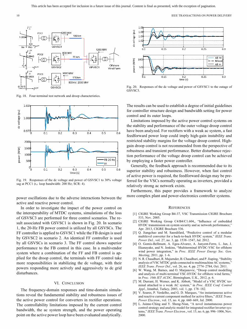
A four-terminal VSC-HVDCmodel, built in the DIgSILENTPowerFactory based on the average-value VSC model, is em-ployed to evaluate the performance of the two active power con-trol structures and their impact on the behaviors of the outerdroop control, under ac fault and converter outage conditions.The network diagram and the droop voltage-power character-istics for grid-side converter stations (GSVSCs) are shown inFig. 18. An identical droop constant of 5% (droop gain: 20) isused for all three GSVSCs. The offshore converter is controlledas a local slack bus to maintain ac voltage and frequency for thewind farm.Simulation of an ac system fault has been performed for the
control scenarios where the FF or the 20-Hz FB power controlis adopted by the droop control for GSVSC1. The responses ofthe dc voltage and power of GSVSC1 are shown in Fig. 19. Thefault causing 30% voltage sag at PCC1 occurs at 0.1 s and iscleared after 150 ms. Severe transients are experienced by theFF case. This is mainly due to the insufficient robustness of theFF control to the ac system voltage. The other reason is that theFF control highly relies on the synchronous frame provided bythe PLL. During severe fault circumstances, the PLLmay not becapable to maintain the alignment and this could result in severe
This article has been accepted for inclusion in a future issue of this journal. Content is final as presented, with the exception of pagination.
10 IEEE TRANSACTIONS ON POWER DELIVERY
Fig. 18. Four-terminal test network and droop characteristics.
Fig. 19. Responses of the dc voltage and power of GSVSC1 to 30% voltagesag at PCC1 ( loop bandwidth: 200 Hz; SCR: 4).
power oscillations due to the adverse interactions between theactive and reactive power control.In order to investigate the impact of the power control on
the interoperability of MTDC systems, simulations of the lossof GSVSC3 are performed for three control scenarios. The re-sult associated with GSVSC1 is shown in Fig. 20. In scenario1, the 20-Hz FB power control is utilized by all GSVSCs. TheFF controller is applied to GSVSC1 while the FB design is usedby GSVSC2 in scenario 2. An identical FF controller is usedby all GSVSCs in scenario 3. The FF control shows superiorperformance to the FB control in this case. In a multivendorsystem where a combination of the FF and FB control is ap-plied for the droop control, the terminals with FF control takemore responsibilities in stabilizing the dc voltage, with theirpowers responding more actively and aggressively to dc griddisturbances.
VI. CONCLUSION
The frequency-domain responses and time-domain simula-tions reveal the fundamental stability and robustness issues ofthe active power control for converters in rectifier operations.The controllability limitations imposed by the current controlbandwidth, the ac system strength, and the power operatingpoint on the active power loop have been evaluated analytically.
Fig. 20. Responses of the dc voltage and power of GSVSC1 to the outage ofGSVSC3.
The results can be used to establish a degree of initial guidelinesfor controller structure design and bandwidth setting for powercontrol and its outer loops.Limitations imposed by the active power control systems on
the stability and performance of the outer voltage droop controlhave been analyzed. For rectifiers with a weak ac system, a fastfeedforward power loop could imply high-gain instability andrestricted stability margins for the voltage droop control. High-gain droop control is not recommended from the perspective ofrobustness and transient performance. Better disturbance rejec-tion performance of the voltage droop control can be achievedby employing a faster power controller.Generally, the feedback approach is recommended due to its
superior stability and robustness. However, when fast controlof active power is required, the feedforward design may be pre-ferred for the VSCs normally operating as inverters, provided arelatively strong ac network exists.Furthermore, this paper provides a framework to analyze
more complex plant and power-electronics controller systems.
REFERENCES
[1] CIGRE Working Group B4-37, VSC Transmission CIGRE Brochure533, Nov. 2005.
[2] CIGRE Working Group C4/B4/C1.604,, “Influence of embeddedHVDC transmission on system security and ac network performance,”Apr. 2013, CIGRE Brochure 536.
[3] Q. Jiangchao and M. Saeedifard, “Predictive control of a modularmultilevel converter for a back-to-back HVDC system,” IEEE Trans.Power Del., vol. 27, no. 3, pp. 1538–1547, Jul. 2012.
[4] O. Gomis-Bellmunt, A. Egea-Alvarez, A. Junyent-Ferre, L. Jun, J.Ekanayake, and N. Jenkins, “Multiterminal HVDC-VSC for offshorewind power integration,” in Proc. IEEE Power Energy Soc. Gen.Meeting, 2011, pp. 1–6.
[5] N. R. Chaudhuri, R.Majumder, B. Chaudhuri, and P. Jiuping, “Stabilityanalysis of VSCMTDC grids connected to multimachine AC systems,”IEEE Trans. Power Del., vol. 26, no. 4, pp. 2774–2784, Oct. 2011.
[6] W. Wang, M. Barnes, and O. Marjanovic, “Droop control modellingand analysis of multi-terminal VSC-HVDC for offshore wind farms,”in Proc. 10th IET ACDC, Birmingham, U.K., 2012, p. 6.
[7] M. Durrant, H. Werner, and K. Abbott, “Model of a VSC HVDC ter-minal attached to a weak AC system,” in Proc. IEEE Conf. ControlAppl., Istanbul, Turkey, 2003, vol. 1, pp. 178–182.
[8] V. Soares, P. Verdelho, and G. D. Marques, “An instantaneous activeand reactive current component method for active filters,” IEEE Trans.Power Electron., vol. 15, no. 4, pp. 660–669, Jul. 2000.
[9] L. Juinne-Ching and Y. Sheng-Nian, “A novel instantaneous powercontrol strategy and analytic model for integrated rectifier/inverter sys-tems,” IEEE Trans. Power Electron., vol. 15, no. 6, pp. 996–1006, Nov.2000.

This article has been accepted for inclusion in a future issue of this journal. Content is final as presented, with the exception of pagination.
WANG et al.: ANALYSIS OF ACTIVE POWER CONTROL FOR VSC–HVDC 11
[10] T. M. Haileselassie and K. Uhlen, “Impact of dc line voltage drops onpower flow of MTDC using droop control,” IEEE Trans. Power Syst.,vol. 27, no. 3, pp. 1441–1449, Aug. 2012.
[11] C. Dierckxsens, K. Srivastava, M. Reza, S. Cole, J. Beerten, and R.Belmans, “A distributed DC voltage control method for VSC MTDCsystems,” Elect. Power Syst. Res., vol. 82, pp. 54–58, 2012.
[12] C. Schauder and H. Mehta, “Vector analysis and control of advancedstatic VAr compensators,” in Proc. Inst. Elect. Eng., Gen. Transm. Dis-trib., 1993, vol. 140, pp. 299–306.
[13] S. Skogestad and I. Postlethwaite, Multivariable Feedback Control:Analysis and Design, 2nd ed. Hoboken, NJ, USA: Wiley, 2005.
[14] B. Jacobson, P. Karlsson, G. Asplund, L. Harnefors, and T. Jonsson,“VSC-HVDC transmission with cascaded two-level converters,” inProc. CIGRE Session, 2010, pp. B4–B110.
[15] R. Marquardt, A. Lesnicar, and J. Hildinger, “Modulares strom-richterkonzept für netzkupplungsanwendung bei hohen spannungen,”ETG-Fachtagung, vol. 88, pp. 155–161, 2002.
[16] A. Antonopoulos, L. Angquist, and H. P. Nee, “On dynamics andvoltage control of the modular multilevel converter,” in Proc. 13thEur. Conf. Power Electron. Appl., 2009, pp. 1–10.
[17] “HVDC: Connecting to the Future,” 1st ed. Alstom Grid, Levallois-Perret, France, 2010.
[18] U. N. Gnanarathna, A. M. Gole, and R. P. Jayasinghe, “Efficient mod-eling of modular multilevel HVDC converters (MMC) on electromag-netic transient simulation programs,” IEEE Trans. Power Del., vol. 26,no. 1, pp. 316–324, Jan. 2011.
[19] T. Qingrui, X. Zheng, and X. Lie, “Reduced switching-frequency mod-ulation and circulating current suppression for modular multilevel con-verters,” IEEE Trans. Power Del., vol. 26, no. 3, pp. 2009–2017, Jul.2011.
[20] A. Lesnicar and R. Marquardt, “An innovative modular multilevelconverter topology suitable for a wide power range,” presented at thePower Tech Conf., Bologna, Italy, 2003.
[21] J. Peralta, H. Saad, S. Dennetiere, J. Mahseredjian, and S. Nguefeu,“Detailed and averaged models for a 401-level MMC HVDC system,”IEEE Trans. Power Del., vol. 27, no. 3, pp. 1501–1508, Jul. 2012.
[22] M. Saeedifard and R. Iravani, “Dynamic performance of a modularmultilevel back-to-back HVDC system,” IEEE Trans. Power Del., vol.25, no. 4, pp. 2903–2912, Oct. 2010.
[23] T. Qingrui and X. Zheng, “Impact of sampling frequency on harmonicdistortion for modular multilevel converter,” IEEE Trans. Power Del.,vol. 26, no. 1, pp. 298–306, Jan. 2011.
Wenyuan Wang (S’12) received the B.Eng. degree in electrical and electronicengineering from The University of Manchester, Manchester, U.K., in 2011,where he is currently pursuing the Ph.D. degree in HVDC systems.His research interests are operation and control of multiterminal VSC-HVDC
systems.
Antony Beddard (S’14) received the M.Eng. degree in electrical and electronicengineering from the University of Manchester, Manchester, U.K., in 2009,where he is currently pursuing the Ph.D. degree in HVDC systems.Hewaswith AlstomGrid, Stafford, U.K. His research is in HVDC technology
for the connection of offshore wind farms.
Mike Barnes (M’96–SM’07) received the B.Eng. and Ph.D. degrees in powerelectronics and drives from the University of Warwick, Coventry, U.K.In 1997, he was a Lecturer with the University of Manchester Institute of
Science and Technology (UMIST), now merged with The University of Man-chester, Manchester, U.K., where he is currently a Professor. His research inter-ests cover the field of power-electronics-enabled power systems.
Ognjen Marjanovic (M’08) received the B.Eng. Hons. degree in electrical andelectronic engineering, Victoria University of Manchester, Manchester, U.K.,and the Ph.D. degree in model predictive control from the School of Engi-neering, Victoria University of Manchester.Currently, he is a Senior Lecturer with the School of Electrical and Electronic
Engineering, The University of Manchester.

![Overview of the Configuration and Power Converters in High ... · Fig. 8. Basic scheme of the LCC-HVDC and VSC-HVDC transmission system [6]. Comparison of the CSC-HVDC and VSC-HVDC](https://img.pdfslide.net/doc/110x75/5ebc0e8dd027f5592e56ad65/overview-of-the-configuration-and-power-converters-in-high-fig-8-basic-scheme.jpg)