Embed Size (px)
Citation preview
International Journal Of Engineering Research And Development e-ISSN: 2278-067X, p-ISSN: 2278-800X, www.ijerd.com Volume 13, Issue 11 (November 2017), PP.37-46
37
Analysis of Compression Struts in The Slab of The Steel- Concrete Composite Beam
*Hyun-Seop Shin1
1Structural Engineering Research Division, Korea Institute of Civil Engineering and Building Technology, 283 Goyangdae-Ro, Ilsanseo-Gu, Goyang-Si, Gyeonggi-Do, 10223, South Korea
Corresponding author: *Hyun-Seop Shin ABSTRACT:- This paper examines the concrete stress state in the shear connection of the composite beam to investigate the effect of the strength and deformation of concrete on the structural behavior of the shear connection. Compression struts are formed inside the slab due to the shear force transferred through the base of the shear studs to the concrete slab. The present study analyzes the stress condition and stress contour developed in these compression struts using a 3-dimensional finite element model. The analysis shows that the exposure of the compression struts to different stress conditions according to their location in the slab influences the load bearing capacity of the shear connection with regard to the shear force. In addition, it appears that the stress conditions are more favorable in term of the load bearing capacity in the zones nearby the center subjected to the external loading than in those around the extremities of the beam. The compression strut exposed to favorable stress conditions is seen to develop relatively larger compressive strength, which leads the shear connection to support larger shear load. Moreover, the relatively higher material stiffness developed by concrete in such case results in smaller deformation of concrete in the shear connection. These deformation characteristics are seen to influence the slip stiffness occurring at the slab-girder interface and explains the different structural behaviors shown by the shear connection according to the location in the slab. Keywords:- composite beam, compression strut, stress state, shear connection, FEM analysis --------------------------------------------------------------------------------------------------------------------------------------- Date of Submission: 15 -11-2017 Date of acceptance: 30-11-2017 --------------------------------------------------------------------------------------------------------------------------------------
I. INTRODUCTION The composite beam combining the steel beam with a concrete slab provides a structure exploiting at
the most the material performances of its constituting members. This configuration, which offers the advantages of reducing the girder depth and shortening the construction period by precasting, makes the composite beam widely applied in the construction sector. Moreover, recent research focuses actively on its application in modular construction. The monolithic behavior of the steel girder and concrete slab is secured by means of shear connectors installed in the steel-concrete interface between these two members. The shear stud is the most preferred type of shear connector. The degree of composite action depends on a multitude of parameters like the number of shear studs or their spacing. In material term, the strength of the shear stud itself is one major parameter as well as the strength or deformation characteristics of the concrete slab. The number of shear studs installed in the composite beam was formerly decided based upon the push-out test results but studies reported some definite difference with the behavior exhibited by the actual composite beam [1-9]. These studies revealed that the composite beam designed by inducing partial interaction achieved a higher degree of composite action or developed strength comparable to that of the composite beam with complete interaction.
The composite beam analyzed in this study is the structure combining monolithically a steel beam and a concrete slab by means of shear studs. This paper intends to evaluate the effect of the strength and deformation characteristics of concrete on the structural behavior of the shear connection by analyzing the stress state in the compression struts of the composite beam using a three-dimensional finite element (FE) model. Compression struts are formed inside the slab by the shear force transferred to the concrete slab via the base of the shear studs. The observation of the stress state in these compression struts allows the analysis of the material behavior and failure mechanism of the shear connection concrete. Moreover, the effect of the material behavior of the shear connection concrete on the slip occurring at the steel-concrete interface is analyzed.
In the present study, the data used in the analysis of the stress state are those calculated in previous finite element analyses [4, 5]. Based upon these stress calculation results, the 3-dimensional principal stress contour and principal stress trajectory are obtained to draw the stress states in the whole slab and in the compression struts. In addition, the 3-dimensional stress states expressed by the triaxial principal stresses are converted into hydrostatic stress and deviatoric stress to analyze more effectively the stress state of the compression strut in the 2-dimensional stress space. The comparison of the difference between the stress states
Analysis of Compression Struts in the Slab of the Steel-Concrete Composite Beam
38
according to the position of the compression struts inside the slab will give insight on the effect of the material behavior of the shear connection concrete on the slip occurring at the steel-concrete interface. The methodology adopted for the stress state analysis relies on the results of a previous study [10] on the analysis method for push-out specimens.
II. FE ANALYSIS MODEL AND STRESS ANALYSIS METHOD 2.1 FE Analysis Model
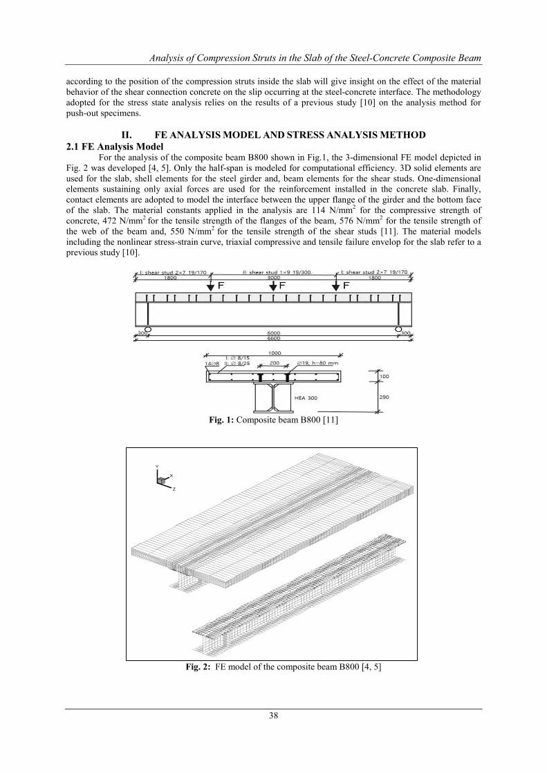
For the analysis of the composite beam B800 shown in Fig.1, the 3-dimensional FE model depicted in Fig. 2 was developed [4, 5]. Only the half-span is modeled for computational efficiency. 3D solid elements are used for the slab, shell elements for the steel girder and, beam elements for the shear studs. One-dimensional elements sustaining only axial forces are used for the reinforcement installed in the concrete slab. Finally, contact elements are adopted to model the interface between the upper flange of the girder and the bottom face of the slab. The material constants applied in the analysis are 114 N/mm2 for the compressive strength of concrete, 472 N/mm2 for the tensile strength of the flanges of the beam, 576 N/mm2 for the tensile strength of the web of the beam and, 550 N/mm2 for the tensile strength of the shear studs [11]. The material models including the nonlinear stress-strain curve, triaxial compressive and tensile failure envelop for the slab refer to a previous study [10].
Fig. 1: Composite beam B800 [11]
Fig. 2: FE model of the composite beam B800 [4, 5]
X
Y
Z
Analysis of Compression Struts in the Slab of the Steel-Concrete Composite Beam
39
2.2 Methodology for the Analysis of Triaxial Stress The region to be primarily analyzed and the reference region for comparison must be selected first to
analyze the stress state of the compression struts formed inside the concrete slab. This first step necessitates a process assessing the region of stress concentration and the location of the compression struts by examination of the stress contour all over the slab. Similarly to a previous method [10], the principal stresses are determined using Equations (1) to (4) for the stresses (σ11, τ12, τ13, σ22, τ21, τ23, σ33, τ31, τ32) obtained by FE analysis [12]. These stresses are then represented visually in the stress contour to allow the overall stress state to be assessed.
(1) where
(2) (3)
(4)
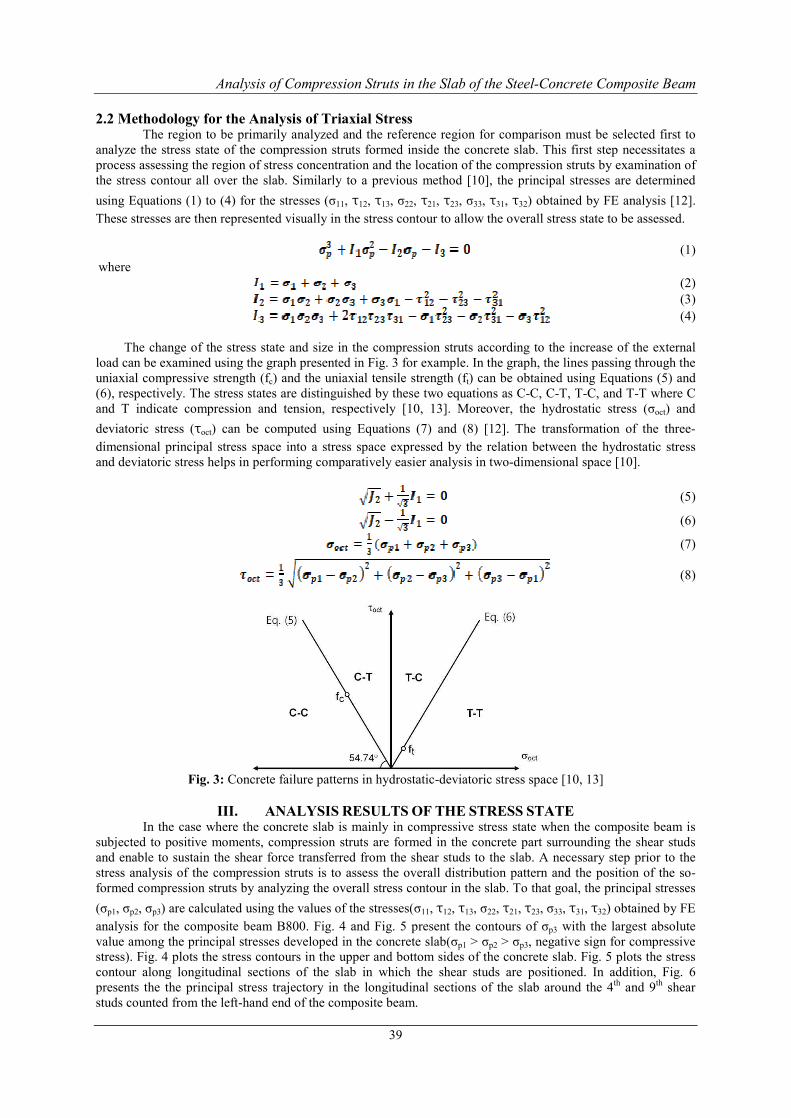
The change of the stress state and size in the compression struts according to the increase of the external load can be examined using the graph presented in Fig. 3 for example. In the graph, the lines passing through the uniaxial compressive strength (fc) and the uniaxial tensile strength (ft) can be obtained using Equations (5) and (6), respectively. The stress states are distinguished by these two equations as C-C, C-T, T-C, and T-T where C and T indicate compression and tension, respectively [10, 13]. Moreover, the hydrostatic stress (σoct) and deviatoric stress (τoct) can be computed using Equations (7) and (8) [12]. The transformation of the three-dimensional principal stress space into a stress space expressed by the relation between the hydrostatic stress and deviatoric stress helps in performing comparatively easier analysis in two-dimensional space [10].
(5)
(6)
(7)
(8)
Fig. 3: Concrete failure patterns in hydrostatic-deviatoric stress space [10, 13]
III. ANALYSIS RESULTS OF THE STRESS STATE
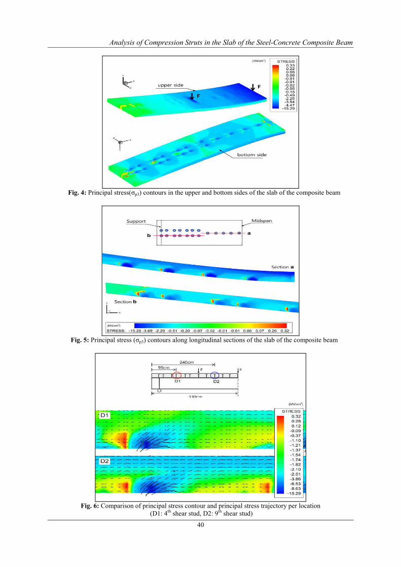
In the case where the concrete slab is mainly in compressive stress state when the composite beam is subjected to positive moments, compression struts are formed in the concrete part surrounding the shear studs and enable to sustain the shear force transferred from the shear studs to the slab. A necessary step prior to the stress analysis of the compression struts is to assess the overall distribution pattern and the position of the so-formed compression struts by analyzing the overall stress contour in the slab. To that goal, the principal stresses (σp1, σp2, σp3) are calculated using the values of the stresses(σ11, τ12, τ13, σ22, τ21, τ23, σ33, τ31, τ32) obtained by FE analysis for the composite beam B800. Fig. 4 and Fig. 5 present the contours of σp3 with the largest absolute value among the principal stresses developed in the concrete slab(σp1 > σp2 > σp3, negative sign for compressive stress). Fig. 4 plots the stress contours in the upper and bottom sides of the concrete slab. Fig. 5 plots the stress contour along longitudinal sections of the slab in which the shear studs are positioned. In addition, Fig. 6 presents the the principal stress trajectory in the longitudinal sections of the slab around the 4th and 9th shear studs counted from the left-hand end of the composite beam.
Analysis of Compression Struts in the Slab of the Steel-Concrete Composite Beam
40
Fig. 4: Principal stress(σp3) contours in the upper and bottom sides of the slab of the composite beam
Fig. 5: Principal stress (σp3) contours along longitudinal sections of the slab of the composite beam
Fig. 6: Comparison of principal stress contour and principal stress trajectory per location
(D1: 4th shear stud, D2: 9th shear stud)
Analysis of Compression Struts in the Slab of the Steel-Concrete Composite Beam
41
In view of the principal stress contour in the bottom side of the concrete slab shown in Fig. 4, the stress is concentrated in the concrete surrounding the base of the shear studs and propagates with a definite inclination angle. This stress contour is very similar to the analytic results of the push-out specimens [10]. The compressive or tensile stresses developed all over the slab and caused by the flexural moment vary continuously along the length of the member according to the size of the flexural moment at the corresponding position. However, the concentrated stress caused by the shear force transferred by the shear studs to the slab exhibits a contour similar to that of the push-out specimens. With regard to the stress contour and stress trajectory described in the longitudinal sections of the slab in Fig. 5 and Fig. 6, the shape of the stress contour becomes relatively unclear at the compression struts between the left support of the beam and the quarterly point. Besides, the compression struts present a definite inclination at proximity of the loading point around the center and their formation can be observed clearly. The difference in the stress contour at the center and the ends can be attributed to the difference in the load transfer mechanism according to the eventual direct application of the external load and to the difference in the degree of the confining stress acting on concrete. The difference observed in the stress contours and trajectories inside the compression struts results from the difference in the degree of concrete cracking and member stiffness. Detailed explanation is given hereafter.
Different stress conditions are developed in the compression struts according to their location inside the
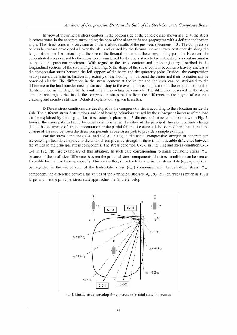
slab. The different stress distributions and load bearing behaviors caused by the subsequent increase of the load can be explained by the diagram for stress states in plane or in 3-dimensional stress condition shown in Fig. 7. Even if the stress path in Fig. 7 becomes nonlinear when the ratios of the principal stress components change due to the occurrence of stress concentration or the partial failure of concrete, it is assumed here that there is no change of the ratio between the stress components in one stress path to provide a simple example.
For the stress conditions C-C and C-C-C in Fig. 7, the actual compressive strength of concrete can increase significantly compared to the uniaxial compressive strength if there is no noticeable difference between the values of the principal stress components. The stress condition C-C-1 in Fig. 7(a) and stress condition C-C-C-1 in Fig. 7(b) are examplary of this situation. In such case corresponding to small deviatoric stress (τoct) because of the small size difference between the principal stress components, the stress condition can be seen as favorable for the load bearing capacity. This means that, since the triaxial principal stress state (σp1, σp2, σp3) can be regarded as the vector sum of the hydrostatic stress (σoct) component and the deviatoric stress (τoct)
component, the difference between the values of the 3 principal stresses (σp1, σp2, σp3) enlarges as much as τoct is large, and that the principal stress state approaches the failure envelop.
(a) Ultimate stress envelop for concrete in biaxial state of stresses
Analysis of Compression Struts in the Slab of the Steel-Concrete Composite Beam
42
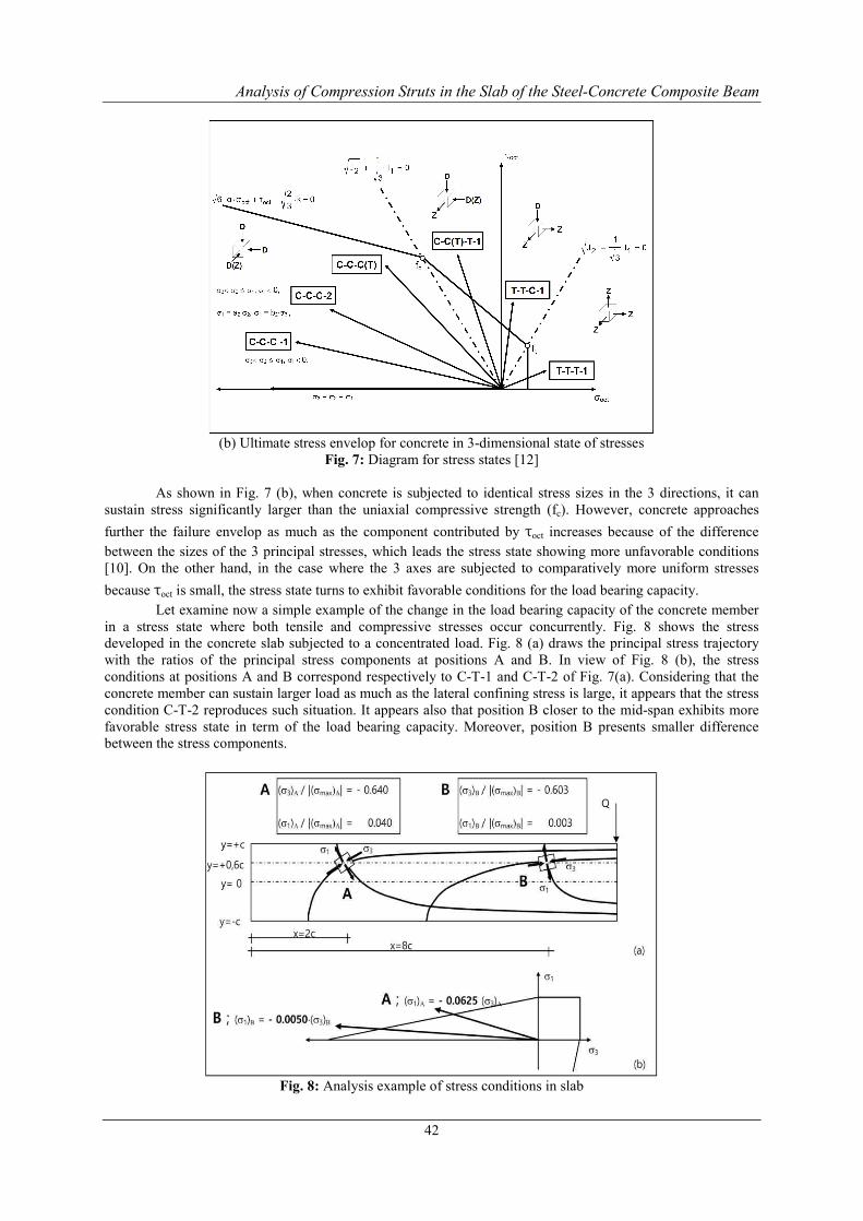
(b) Ultimate stress envelop for concrete in 3-dimensional state of stresses
Fig. 7: Diagram for stress states [12]
As shown in Fig. 7 (b), when concrete is subjected to identical stress sizes in the 3 directions, it can sustain stress significantly larger than the uniaxial compressive strength (fc). However, concrete approaches further the failure envelop as much as the component contributed by τoct increases because of the difference between the sizes of the 3 principal stresses, which leads the stress state showing more unfavorable conditions [10]. On the other hand, in the case where the 3 axes are subjected to comparatively more uniform stresses because τoct is small, the stress state turns to exhibit favorable conditions for the load bearing capacity.
Let examine now a simple example of the change in the load bearing capacity of the concrete member in a stress state where both tensile and compressive stresses occur concurrently. Fig. 8 shows the stress developed in the concrete slab subjected to a concentrated load. Fig. 8 (a) draws the principal stress trajectory with the ratios of the principal stress components at positions A and B. In view of Fig. 8 (b), the stress conditions at positions A and B correspond respectively to C-T-1 and C-T-2 of Fig. 7(a). Considering that the concrete member can sustain larger load as much as the lateral confining stress is large, it appears that the stress condition C-T-2 reproduces such situation. It appears also that position B closer to the mid-span exhibits more favorable stress state in term of the load bearing capacity. Moreover, position B presents smaller difference between the stress components.
Fig. 8: Analysis example of stress conditions in slab
Analysis of Compression Struts in the Slab of the Steel-Concrete Composite Beam
43
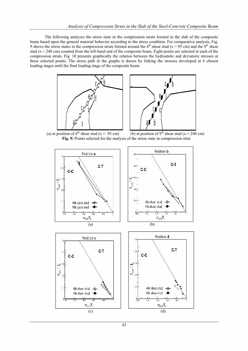
The following analyzes the stress state in the compression struts formed in the slab of the composite beam based upon the general material behavior according to the stress condition. For comparative analysis, Fig. 9 shows the stress states in the compression struts formed around the 4th shear stud (x = 95 cm) and the 9th shear stud (x = 240 cm) counted from the left-hand end of the composite beam. Eight points are selected in each of the compression struts. Fig. 10 presents graphically the relation between the hydrostatic and deviatoric stresses at these selected points. The stress path in the graphs is drawn by linking the stresses developed at 6 chosen loading stages until the final loading stage of the composite beam.
(a) at position of 4th shear stud (x = 95 cm) (b) at position of 9th shear stud (x = 240 cm)
Fig. 9: Points selected for the analysis of the stress state in compression strut
(a) (b)
(c) (d)

Analysis of Compression Struts in the Slab of the Steel-Concrete Composite Beam
44
(e) (f)
(g) (h)
Fig. 10: Hydrostatic-deviatoric stress relation at selected points (a-h) in compression struts
The comparison reveals that the stress developed in the compression strut did not vary noticeably according to the position in the strut from the bottom of the slab (position a) to the center of the section (position d), and that most of the stress conditions are C-C. However, the comparison of the stress state at the top of the compression struts from position e to position h shows that the compression strut located at the 4th shear stud developed comparatively unfavorable stress condition being mostly in C-T condition from the start to the final loading stage. These contradictory stress states can be explained as follows. For the base of the compression strut (position a to d), the stress concentration provoked by the shear force acting on the interface has the strongest contribution to the overall stress state. On the other hand, for the top of the compression strut (position e to h), the stress state provoked by the flexural moment in the level of whole structural system seem to be reflected in the stress of the compression strut. This observation is represented visually in the stress contour in Fig. 4, Fig. 5 and Fig. 6.
However, the comparison of the stress state at positions c and d in the compression strut shows that the deviatoric stress is relatively smaller in the compression strut located at the 4th shear stud, which indicates faborable stress condition. Even if it is difficult to perform a synthetic analysis showing that this case is different to the overall tendency, this situation can be explained as follows with regard to the results shown in the graphs. For the positions c and d of the compression strut located at the 4th shear stud, the stress state is relatively less influenced by the concrete failure caused by local stress concentration or unfavorable stress condition over the whole structural system. This result can be attributed to the small difference between the stress components leading to the occurrence of smaller deviatoric stress. Moreover, in structural terms, the fact that the shear studs are arranged in two rows from the ends to the quarter-lengths of the composite beam makes the concrete section subject to comparatively more uniform loading, which leads to the occurrence of smaller deviatoric stress. This topic should be investigated analytically in further studies. Fig. 11 plotting the shear force-slip relation of the studs provides examples of the effect of the mutually different stress states of the compression struts on the structural behavior of the shear connection at the interface. The slip stiffness of the 9th shear stud appears to be much larger than that of the 4th shear stud.

Analysis of Compression Struts in the Slab of the Steel-Concrete Composite Beam
45
Fig. 11: Comparison of shear stud behaviors in composite beam B800 (a/b/c: 4th/7th/9th shear stud)
Fig. 12: Comparison of axial compressive stress-strain relation according to size of lateral confining stress [14]
Furthermore, Fig. 12 relates the change of the concrete material stiffness to the stress state in the
hydrostatic-deviatoric stress space according to the lateral confining stress (σ2 and σ3). Conceptually speaking, Fig. 12 explains the cause of the difference in the slip stiffness according to the position of the shear stud in the composite beam. When the compression strut subjected to compressive stress (σ1) is exposed to higher
confining stress (σ2 and σ3) than that at another position in the slab, the compressive strength appears to be much larger than the uniaxial compressive strength as shown in the ideal condition of Fig. 12, and the stiffness also is seen to increase. Such state corresponds to a stress condition favorable for the increase of the load bearing capacity of concrete, and relates to the case where the deviatoric stress is smaller due to the relatively small difference between the stress components (σ1, σ2 and σ3). When the stress condition is favorable in term of the load bearing capacity owing to relatively small deviatoric stress developed in the concrete member, the material stiffness of the concrete member is relatively larger, which in turn influences the slip stiffness of the shear connection. Consequently, it can be stated that the structural behavior of the shear connection in the composite beam is influenced not only by the deformation of the shear stud itself but also by the stress condition and stress state developed in the compression strut.
IV. CONCLUSIONS When the composite beam is under positive moment leading the concrete slab to be in compressive
stress state, compression struts are formed in the shear connection concrete surrounding the shear studs and allow the shear force transferred from the shear studs to the slab to be sustained. This study analyzed the stress state of the compression struts using 3-dimensional FE model to examine the effect of the stress condition and state generated in the compression strut on the structural behavior of the interfacial shear connection. The results showed that the compression struts developed mutually different stress conditions according their location inside the slab of the composite beam. It appeared that the failure behavior of concrete with respect to these different
Analysis of Compression Struts in the Slab of the Steel-Concrete Composite Beam
46
stress conditions and the increase of the load influenced the load bearing capacity for the shear force occurring at the interface. The stress condition was seen to be more favorable to the load bearing capacity in the zone neighboring the center of the composite beam near the loading point than in the zones close to the ends of the composite beam. The compression strut exposed to favorable loading condition developed relatively higher compressive strength, which also increased the size of the shear force sustained by the shear connection. Moreover, in this case, the deformation of the shear connection concrete (i.e., the compression strut) reduced since the material stiffness of concrete was also comparatively higher. Such deformation characteristics influenced the slip stiffness at the interface, and resulted in different structural behaviors of the shear connection according to the location inside the slab.
REFERENCES
[1]. H. Bode, J. Schanzenbach, “Das Tragverhalten von Verbundträgern bei Berücksichtigung der Dübel- nachgiebigkeit”, Stahlbau 58, Heft 3, pp. 65-74, 1989.
[2]. H. Bode, European Steel-Concrete Composite Structure, Construction and Calculation, Werner Verlag, 1998.
[3]. R. P. Johnson, Composite Structures of Steel and Concrete, volume 1: Beams, Columns, Frames and Applications in Building, London, 1975.
[4]. H. S. Shin, A Contribution to the Numerical Analysis of the Load Carrying Behaviour of the Composite Beams with High Strength Steel and High Strength Concrete, Dissertation, RWTH-Aachen University, 2004.
[5]. H. S. Shin, FEM Analysis of the Horizontal Shear Behaviour in the Steel-Concrete Composite Beam, International Journal of Engineering Research and Development, Volume 10, Issue 9, 2014.
[6]. A. Shariati, N. H. RamliSulong, MeldiSuhatril, M. Shariati, “Various Types of Shear Connectors in Composite Structures”: A Review, International Journal of Physical Sciences, Vol.7, no.22, pp.2876-2890, 2012.
[7]. M. G. Navarro, J. P. Lebet, “Tests on Cracked Composite Beams for Bridges”, Theori und Praxis im konstruktiven Ingenieurbau, Festschrift zu Ehren von Prof. Dr.-Ing. H. Bode, Ibidem Verlag, pp.521-532, Stuttgart, 2000.
[8]. J. M. Aribert, “Application and Recent Development of a Numerical Model for Composite Beams with Partial Shear Connection”, Composite Construction in Steel and Concrete II, Proceedings of an Enginnering Foundation Conference, pp.742-757, Potosi, Missouri, USA, 1992.
[9]. J. M. Aribert, A. Al Bitar, Optimization of the Design in Partial Connection of Beams in Composite Floors with Thin Profiled Steel Sheeting, Construction Metallique, No.4, pp.3-33, 1989
[10]. H. S. Shin, Analysis of failure behavior of shear connection in push-out specimen by three-dimensional stress analysis, International Journal of Engineering Research and Development, Volume 13, Issue 7, 2017.
[11]. Hoffmeister, B., Sedlacek, G., Müller, Ch., Use of High Strength Steel S460, Composite beams made of high strength steel and high strength concrete, RWTH Aachen, 2000.
[12]. Stempniewski, L., Eibl, J.: Finite Elemente im Stahlbeton. Beton Kalender, Teil 1, Ernst & Sohn Verlag, 1993
[13]. Boresi, A.P., Sidebottom, O.M., Seely, F.B., Smith, J.O., Advanced Mechanics of Materials, John Willy and Sons, 1978.
[14]. Balmer, G.G., Shearing Strength of Concrete under High Triaxial Stress – Computation of Mohr’s Envelope as a Curve. Structural Research Laboratory Report No. SP-23, Bureau of Reclamation, United States Department of Interior, 1949.
*Hyun-Seop Shin. “Analysis of Compression Struts in The Slab of The Steel- Concrete Composite Beam.” International Journal Of Engineering Research And Development , vol. 13, no. 11, 2017, pp. 37–46.