Embed Size (px)
Citation preview

CHALMERS
ANALYSIS OF CONFORMAL
ANTENNAS FOR AVIONICS
APPLICATIONS
by
María del Carmen Redondo González
Supervisor: Eduardo Schittler Neves
Examiner: Prof. Per-Simon Kildal
January 2007
Chalmers University of Technology
International Master’s in “Hardware for Wireless Communications”
Gothenburg, Sweden
DLR (German Aerospace Center)
Institute for Communications and Navigation
Oberpfaffenhofen, Germany

I
To my Mother

II
ABSTRACT
Conformal antennas might have an important impact on communication and navigation applications on aircraft, ships and other vehicles. This thesis work presents a general study on conformal antennas and their potential application on aircraft structures. Several electromagnetic simulations are performed in order to provide a comparative analysis of arbitrary conformal antennas with their planar counterparts and determine the advantages and disadvantages of each case. The worthiness of integrating these antennas on aircraft fuselages is investigated by simulating the antennas on an aircraft footprint. In addition, a new type of conformal antenna is introduced. Some attractive characteristics of this antenna are its nearly omnidirectional radiation patterns and its small physical size compared to other microstrip antennas of the same frequency range. A prototype of this new structure is designed for the Galileo frequency band E1 (1.559 - 1.591 GHz) and circular polarization in one hemisphere.

III
PREFACE
This report, together with a presentation, is the result of the thesis for the international master’s in “Hardware for Wireless Communications” of Chalmers University of Technology. It has been developed at the German Aerospace Center - Deutsches Zentrum für Luft- und Raumfahrt e.V. (DLR) in the Institute for Communications and Navigation, particularly in the antenna department, during the period from June 2006 to January 2007.
The supervisor of this project at DLR is Eduardo Schittler Neves and the examiner at Chalmers University of Technology is Prof. Per-Simon Kildal.

IV
TABLE OF CONTENTS
ABSTRACT II PREFACE III LIST OF FIGURES VI LIST OF TABLES IX ABBREVIATIONS AND ACRONYMS X 1. INTRODUCTION 1
2. OVERVIEW OF CONFORMAL ANTENNAS 3
2.1. Literature Review 4
2.1.1. The Circularly Polarized Cylindrical Patch 5
2.1.2. Omnidirectional Stacked Patch Antenna Printed on Circular Cylindrical
Structure 6
3. ANALYSES OF CONFORMAL MICROSTRIP ANTENNAS 7
3.1. Conformal Antennas on Singly Curved Surfaces 7
3.1.1. Cylindrical Microstrip Antenna Analyses for Large Radii 8
3.1.1.1. Radius Variation Analysis 10
3.1.1.2. Relative Permittivity Variation Analysis 12
3.1.1.3. Substrate Thickness Variation Analysis 14
3.1.2. Cylindrical Microstrip Antenna Analyses for Small Radii 16
3.2. Conformal Antennas on Doubly Curved Surfaces 20
3.2.1. Spherical Microstrip Antenna 20
3.2.2. Toroidal Microstrip Antenna 22
3.3. General Characteristics of Conformal Antennas Compared with their Planar
Counterparts 22

V
3.3.1. Quasi-squared Conformal Microstrip Antennas 22
3.3.2. Wraparound Conformal Microstrip Antennas: Omnidirectional Radiation
Patterns 24
3.4. Advantages and Disadvantages of Employing Conformal Antennas 25
4. THE QUASI-OMNIDIRECTIONAL TOROIDAL MICROSTRIP ANTENNA 27
4.1. ARINC Specifications for the ANASTASIA project 27
4.2. Antenna Design 28
4.3. Simulation Results 31
4.3.1. Toroidal Microstrip Antenna Performance 31
4.3.2. Parametric Study 35
4.4. Manufacture 37
5. EFFECTS OF THE AIRCRAFT FOOTPRINT 39
5.1. Antenna Position on the Aircraft 39
5.2. Simulation Results 40
6. CONCLUSIONS & FUTURE WORK 47 REFERENCES 48
ACKNOWLEDGMENTS 51
APPENDICES 52
A. Fundamentals of Microstrip Antennas 52
A.1. Feeding Techniques 52
A.2. Enhancing Bandwidth Techniques 54
B. Electromagnetic Analysis Tools 55
B.1. CYLINDRICAL: Cavity Model Analysis 55
B.2. HFSSTM: Finite Element Method Analysis (FEM) 56
B.3. Simulation Comparison 57
VI
LIST OF FIGURES Fig. 2.1: Examples of conformal antennas from Ball Aerospace and EWCA ......................3
Fig. 2.2: Geometry of the circularly polarized cylindrical patch ..........................................5
Fig. 2.3: Geometry of the cylindrical stacked patch antenna ................................................6
Fig. 3.1: Structure of the reference cylindrical microstrip antenna simulated in
CYLINDRICAL ........................................................................................................9
Fig. 3.2: RHCP spinned radiation pattern for the reference cylindrical microstrip
antenna at 2.25GHz .................................................................................................9
Fig. 3.3: Return loss for radii between 1.8755λ0 and 4.8762λ0 ...........................................10
Fig. 3.4: Axial ratio for radii between 1.8755λ0 and 4.8762λ0 ............................................10
Fig. 3.5: Normalized E-field radiation patterns for different radii at 2.25 GHz .................11
Fig. 3.6: Return loss for different relative permittivities .....................................................12
Fig. 3.7: Axial ratio for different relative permittivities ......................................................12
Fig. 3.8: Normalized E-field radiation patterns for different relative permittivities at
2.25 GHz ...............................................................................................................13
Fig. 3.9: Return loss for different substrate thickness .........................................................14
Fig. 3.10: Axial ratio for different substrate thickness ..........................................................14
Fig. 3.11: Normalized E-field radiation patterns for different substrate thickness at
2.25 GHz ...............................................................................................................15
Fig. 3.12: Return loss for the reference antenna dimensions for 250 mm and 40 mm
radius .....................................................................................................................16
Fig. 3.13: Normalized E-field radiation patterns for different small radii at 2.25 GHz ........17
Fig. 3.14: Geometry of the cylindrical microstrip antenna ...................................................18
Fig. 3.15: Aspect ratio versus radius of the curved patch .....................................................18
Fig. 3.16: 3-dB AR bandwidth versus radius of the curved patch ........................................19
Fig. 3.17: Geometry of the quasi-square spherical microstrip antenna .................................20
Fig. 3.18: Polarization definitions according to Ludwig .......................................................21
Fig. 3.19: Geometry of the quasi-square toroidal microstrip antenna ...................................22
Fig. 3.20: Conformal antennas and their planar counterpart simulated in HFSSTM ..............23
Fig. 3.21: Normalized E-field radiation patterns for different antenna geometries at
2.25 GHz ...............................................................................................................23
Fig. 3.22: Wraparound patch antennas simulated in HFSSTM ...............................................24

VII
Fig. 3.23: Normalized E-field radiation patterns for the wraparound patch antenna in a
cylinder and in a torus at 1.575 GHz ....................................................................25
Fig. 4.1: Probe-fed toroidal microstrip antenna geometry ..................................................28
Fig. 4.2: Microstrip transmission line parameters ...............................................................29
Fig. 4.3: Microstripline-fed toroidal microstrip antenna geometry .....................................30
Fig. 4.4: Dimensions of the probe-fed toroidal microstrip antenna prototype .....................30
Fig. 4.5: Normalized E-field radiation patterns for the probe-fed toroidal microstrip
antenna at 1.575 GHz ............................................................................................32
Fig. 4.6: Return loss for the probe-fed toroidal microstrip antenna ....................................32
Fig. 4.7: Axial ratio for the probe-fed toroidal microstrip antenna in the upper
hemisphere ............................................................................................................33
Fig. 4.8: Normalized E-field 3D radiation patterns for the probe-fed toroidal microstrip
antenna at 1.575 GHz ............................................................................................33
Fig. 4.9: Normalized E-field radiation patterns for the microstripline-fed toroidal
microstrip antenna at 1.575 GHz ..........................................................................34
Fig. 4.10: Return loss for the microstripline-fed toroidal microstrip antenna .......................34
Fig. 4.11: Axial ratio for the microstripline-fed toroidal microstrip antenna in the upper
hemisphere ............................................................................................................35
Fig. 4.12: Normalized E-field radiation patterns for different torus radii at 1.575 GHz ......36
Fig. 4.13: Normalized E-field radiation patterns for different inner radii at 1.575 GHz ......36
Fig. 5.1: Antenna evaluation ground plane and position on the aircraft .............................39
Fig. 5.2: Position of the conformal antennas on the aircraft footprint for the HFSSTM
simulations ............................................................................................................40
Fig. 5.3: Normalized E-field radiation patterns for different structures placed along the
footprint surface at 1.575 GHz ..............................................................................41
Fig. 5.4: Normalized E-field radiation patterns for different structures placed 6.5 cm
over the footprint at 1.575 GHz ............................................................................41
Fig. 5.6: Normalized E-field radiation patterns for different structures and positions on
the footprint at 1.575 GHz ....................................................................................42
Fig. 5.7: Different positions of the toroidal microstrip antenna on the aircraft footprint
for the HFSSTM simulations ..................................................................................43
Fig. 5.8: 3D-view of the normalized E-field radiation patterns for the probe-fed
toroidal microstrip antenna on the aircraft footprint at 1.575 GHz ......................44

VIII
Fig. 5.9: Different positions of the toroidal microstrip antenna on the aircraft footprint
for the HFSSTM simulations ...................................................................................45
Fig. 5.10: Normalized E-field radiation patterns for the cylindrical and the toroidal
antenna on the footprint at 1.575 GHz ..................................................................45
Fig. A.1a: Microstrip patch antenna E-fields .........................................................................52
Fig. A.1b: Probe-fed microstrip patch antenna geometry ......................................................52
Fig. A.2: Microstrip patch antenna feeding techniques .......................................................53
Fig. A.3: Microstrip patch antenna enhancing bandwidth techniques .................................54
Fig. B.1: CYLINDRICAL simulation tool user interface ......................................................55
Fig. B.2: Initial mesh on a cylindrical geometry in HFSSTM ...............................................56
Fig. B.3: Mesh operations setup in HFSSTM ........................................................................56
Fig. B.4: Normalized E-field radiation patterns at 2.25 GHz simulated in CLYINDRICAL
and HFSSTM ...........................................................................................................58

IX
LIST OF TABLES TABLE 3.1: Advantages and disadvantages of conformal antennas compared to planar
ones ....................................................................................................................26
TABLE 4.1: ARINC specifications ........................................................................................27
TABLE 4.2: Dimensions of the toroidal microstrip antenna prototype ..................................31
TABLE 4.3: Sensitivity of the probe position ........................................................................37
TABLE 5.1: RHCP coverage for different positions of the toroidal microstrip antenna on
the aircraft footprint ...........................................................................................46

X
ABBREVIATIONS AND ACRONYMS ANASTASIA: Airbone New and Advanced Satellite Techniques & Technologies in A System Integrated Approach AR: Axial Ratio ARINC: Aeronautical Radio Inc. ASP: Aperture-Stacked Patch CAD: Computer Aided Design DLR: Deutsches Zentrum für Luft- und Raumfahrt e.V, German Aerospace Center EM: Electromagnetic EWCA: European Workshop on Conformal Antennas FEM: Finite Element Method GLONASS: GLObal NAvigation Satellitle System GPS: Global Positioning System MMIC: Microwave Monolithic Integrated Circuits RCS: Radar Cross Section RHCP: Right Hand Circular Polarization RL: Return Loss VSWR: Voltage Standing Wave Ratio XPD: Cross Polarization Decoupling

Introduction
- 1 -
1. INTRODUCTION
As the improvements on the communication and navigation systems of aircrafts go on, new edge-cutting technologies are developed and new approaches to the system components are required. The antenna represents the interface between the transmitted and/or received microwaves traveling on free space and the signal processing hardware and software. Optimizing the antenna characteristics can lead to great improvements to the overall system performance, like lower noise figures, suppressed multipath and interference signals and higher signal levels, i.e. better accuracy, better aerodynamics, lighter weight, etc.
One of the biggest questions of the moment is the one regarding the worthiness of utilizing conformal structures instead of their planar counterparts for installation on different aircraft fuselages. Therefore, a comparative analysis between conformal and non-conformal (planar) antennas is required to determine the advantages and disadvantages of each case.
In addition, this project is directly linked to the project ANASTASIA (Airbone New
and Advanced Satellite Techniques & Technologies in A System Integrated Approach), which brings together several European partners. ANASTASIA aims to carry out research and evaluation of new communication and navigation technologies in the future satellite-based European air traffic management environment. The expected performances of space based technologies such as Satellite communications (Satcom) and Satellite Navigation (renewed GPS, Galileo) offer the possibility of increased autonomous aircraft operation that will improve the operational capacity and safety of the air transport system with regard to the “Single European Sky” initiative [29].
The present work is related specifically to conformal antennas. Its main purpose is to
carry out a research of this type of antennas for aircraft navigation applications. In brief, the objectives of this project are:
- General conformal antenna study - Comparison between conformal and planar antennas
- To determine the effects of the aircraft footprint on the antenna parameters
- To design a conformal antenna according to most of the ARINC (Aeronautical
Radio, Inc.) specifications
Introduction
- 2 -
This report is organized in five sections. In section 2, conformal antennas are briefly introduced. In addition, in order to provide an overview of the present research status, a literature review is carried out. In section 3, a general study of conformal antennas is presented. Several types of conformal antennas are studied, being them divided into two groups: singly and doubly curved antennas. In particular, cylindrical antennas are analyzed in more detail by varying their physical parameters in order to observe the effects on the performance. After that, the different conformal antennas are directly compared with their planar counterparts by means of electromagnetic (EM) simulations. Finally, the section concludes with the advantages and disadvantages of employing conformal antennas. In section 4, a new type of conformal antenna is presented. The quasi-omnidirectional toroidal antenna is designed for broad coverage. The design process is commented together with a parametric study that will provide a better understanding of the antenna performance. Also, the most relevant simulation results are presented to show its characteristics. In the end of the section, the materials and the manufacturing procedure of such an antenna are clarified. In section 5, the effects of the aircraft footprint on the antenna characteristics are presented. All the antennas studied in previous sections are analyzed together with the footprint. Finally, conclusions about the project are commented and future work is proposed in the last part of the report, section 6.
Overview of Conformal Antennas
- 3 -
2. OVERVIEW OF CONFORMAL ANTENNAS
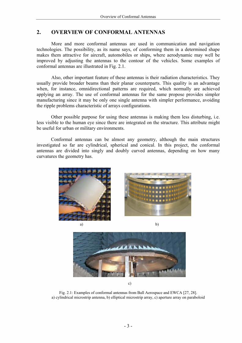
More and more conformal antennas are used in communication and navigation technologies. The possibility, as its name says, of conforming them in a determined shape makes them attractive for aircraft, automobiles or ships, where aerodynamic may well be improved by adjusting the antennas to the contour of the vehicles. Some examples of conformal antennas are illustrated in Fig. 2.1.
Also, other important feature of these antennas is their radiation characteristics. They usually provide broader beams than their planar counterparts. This quality is an advantage when, for instance, omnidirectional patterns are required, which normally are achieved applying an array. The use of conformal antennas for the same propose provides simpler manufacturing since it may be only one single antenna with simpler performance, avoiding the ripple problems characteristic of arrays configurations.
Other possible purpose for using these antennas is making them less disturbing, i.e. less visible to the human eye since there are integrated on the structure. This attribute might be useful for urban or military environments.
Conformal antennas can be almost any geometry, although the main structures investigated so far are cylindrical, spherical and conical. In this project, the conformal antennas are divided into singly and doubly curved antennas, depending on how many curvatures the geometry has.
a) b)
c)
Fig. 2.1: Examples of conformal antennas from Ball Aerospace and EWCA [27, 28]. a) cylindrical microstrip antenna, b) elliptical microstrip array, c) aperture array on paraboloid

Overview of Conformal Antennas
- 4 -
2.1. Literature Review An extensive literature search was undertaken [1-25] in order to determine the current
state of the art of conformal antennas. Some works from the literature which present potentially advantages that could be used within the project are shown in this section.
Bibliography in the field of conformal antennas is still limited. Two relevant books
were found: “Design of Non-planar Microstrip Antennas and Transmission Lines” [14] and the recent publication “Conformal Array Antenna Theory and Design” [15]. The former concentrates mainly in methods of analysis and resonance and coupling problems in conformal microstrip lines and antennas. It provides information regarding the polarization in cylindrical antennas, which are interesting for the study of this project. The latter focuses mostly in conformal array configurations, although single antennas are also analyzed. It includes abundant theory, simulations and measurements that make it a significant book in this field. In particular for this project, the book was very useful for a first insight into conformal antennas and, more in detail, for verification of the results and conclusions achieved through this project.
Cylindrical antennas are the most established in the conformal antenna field and most
of the references found are related to this geometry [2-15]. The next more studied structure is the sphere [14-18]. Apart from these two representative conformal antennas, literature is reduced when analyzing conical, elliptical or other geometries.
Most of the publications study methods of analysis suitable for non-planar structures. Different theoretical techniques are employed depending on the geometry although, in general, if the surface is electrically small almost any type of method can be used [15]. In many cases, the analysis of conformal antennas can be based on approximate techniques and when the antenna has very large radii of curvature, it may be often analyzed as if it were planar [7]. Other important factor for the method selection is the accuracy and time consumption since, for instance, the cavity model is relatively fast but not as accurate as the full-wave analysis (see APPENDIX B). As example, in [7] the spectral domain approach is used to study the radiation pattern and input impedance of a rectangular patch antenna on an infinitely long cylinder. The Fourier transform is applied to the fields and the Green’s function of the structure is evaluated in the spectral domain. Then, the unknown current distribution of the patch, needed to obtain the radiation patterns, is calculated using the moment method. Other example of a different theoretical technique can be found in [16], where a wraparound patch mounted on a sphere is replaced by an equivalent current based on the cavity model theory. The accuracy of this method is confirmed in the publication by a more rigorous but complex theoretical approach based on the electric surface current model. These publications are interesting to learn about methods of analysis. However, the study of these techniques is not indispensable for the scope of this project since designs and analyses are carried out with EM simulators that use these methods.
Through the examples enclosed in most of the papers, characteristics of different
types of conformal antennas can be studied. Regarding the radiation pattern, reference [5] presents a cylindrical antenna with almost hemispherical coverage. The drawback of this design is the substrate thickness, which is very thick. Two publications [11, 12] show designs with particularly interesting radiation pattern characteristics and are commented in more detail. The first one presents a wraparound antenna conformed on a cylinder with omnidirectional radiation pattern in the azimuth plane. The second shows a bandwidth improvement of the former by using a stacked patch antenna with an air gap in the cylinder.

Overview of Conformal Antennas
- 5 -
6.1.1. The Circularly Polarized Cylindrical Patch The circular cylindrical omnidirectional patch antenna has been studied by some authors [9-13]. As an example, here is presented the publication which has analyzed the performance of this type of antenna for circular polarization [11] unlike other authors. The type of antenna presented in this publication has a nearly omnidirectional radiation pattern in the azimuth plane and a dipole-like radiation pattern in the elevation plane. The antenna is a microstrip patch wrapped around a grounded dielectric cylinder. It is fed by a single coaxial probe placed in order to generate circular polarization. The antenna is optimized for 1.92 GHz. The geometry of this antenna is illustrated in Fig. 2.2. The parameters of the antenna are: relative permittivity of the substrate εr = 4.2, diameter of the ground plane cylinder ΦGND = 1.2 cm, diameter of the patch ΦPatch = 1.36 cm, width of the patch W = 1.98 cm and angular gap φ = 25.8°. The feed point is offset in respect to the z-axis and φ-axis by Δz = 1.9 cm and Δφ = 18.9°.
a. Axial cut b. Longitudinal cut
Fig. 2.2: Geometry of the circularly polarized omnidirectional cylindrical patch
As commented above, the radiation pattern is nearly omnidirectional in the azimuth plane, presenting 0.2 dB of omnidirectionality. This is a result of the small diameter of the cylindrical patch in terms of wavelengths. In the elevation plane the radiation pattern is a dipole-like one. The antenna is quite narrowband presenting a bandwidth less than 1%. However, other feeding methods in addition to the use of a dielectric substrate with a lower permittivity or a thicker dielectric could be applied to the design in order to overcome the narrow bandwidth.

Overview of Conformal Antennas
- 6 -
6.1.2. Omnidirectional Stacked Patch Antenna Printed on Circular Cylindrical Structure
This design is similar to the previous one, with the addition of an air gap and a parasitic element in order to improve the bandwidth [12]. The geometry of the cylindrical stacked patch antenna, as can be seen in Fig. 2.3, consists of an inner ground cylinder with a radius of 1.42 cm and two substrates with a relative permittivity of εr = 2.3 separated by an air gap. The inner dielectric has a radius of rinner = 1.422 cm and a thickness of 1.8 mm while the outer dielectric has a radius of router =1.852 cm and a thickness of 1.6 mm. In this case a driven patch is used to feed the antenna, having 2.53 cm of length and 5.30 cm of width. The driven patch (inner patch) is fed by a coaxial probe placed 2.18 cm below its center. The wraparound patch has the following dimensions: 10 cm length and 5.42 cm width. Both patches are centered, i.e. their centers lay on a line perpendicular to the axis of the cylinder.
Fig. 2.3: Geometry of the cylindrical stacked patch antenna
The relative RL bandwidth of the antenna is 13.4%, from 1.81 GHz to 2.07 GHz, much improved in comparison to the previous model. The radiation pattern still remains nearly omnidirectional, with approximately 4 dB of omnidirectionality in the azimuth plane. Unlike the previous antenna, this one is designed for liner polarization. However, circular polarization could be obtained by changing the feed position or by adding a second probe with the appropriate phase shift.
rinner router

Analyses of Conformal Microstrip Antennas
- 7 -
3. ANALYSES OF CONFORMAL MICROSTRIP ANTENNAS
The main interest of this section is to analyze the characteristics and the performance of different types of conformal antennas. The knowledge gained through this study will be useful for the conformal antenna design presented in section 4.2.
As mentioned previously, in this project the conformal antennas are divided into two
categories called singly and doubly curved, depending on how many curvatures the geometry of the antenna has. In each category, first some theoretical considerations are introduced and then, the different types of antennas are analyzed.
The study begins with the cylindrical antenna, for which a series of variation analyses
are undertaken in order to evaluate its performance. After that, characteristics of doubly curved antennas under different conformability conditions are investigated.
This study also includes a comparison among the simulation results from all the
conformal antennas analyzed and their planar counterparts.
Finally, as a conclusion of the study, the advantages and disadvantages of conformal antennas over the planar ones are presented. 3.1. Conformal Antennas on Singly Curved Surfaces
Antennas on singly curved surfaces are the simplest conformal antennas. The main purpose of such antennas is to improve the azimuth coverage, obtaining even in some cases omnidirectional coverage. Especially the circular cylindrical antenna is commonly used in conformal antenna applications since it is one of the most straightforward non-planar geometry. The conical antenna is also in a singly curved surface with particular interest for applications in the noses of aircraft or missiles [15]. However, in this section only cylindrical antennas will be treated due to their simple geometry.
The dimensions of the cylindrical antennas studied in this section, illustrated in Fig. 3.1, are calculated by the cavity model. The algorithm used follows the procedure described in [20] and the probe position is found using an iterative process proposed by [26]. The probe must be placed in the specific point that excites the modes TM01 (z-direction excitation) and TM10 (φ-direction excitation) with the same amplitude and 90º phase difference in order to produce RHCP. For this, the feeding must be selected in the diagonal of the quasi-square patch [22] so that
ll
bz '2
'= (3.1)
where the parameters are illustrated in Fig. 3.1.
An approximate value of the resonance frequency can be found by using a planar solution. The resonant frequency for the mnth TM mode is given by [15]:
2122
2 ⎥⎥⎦
⎤
⎢⎢⎣
⎡⎟⎠⎞
⎜⎝⎛+⎟
⎠⎞
⎜⎝⎛=
Ln
Wmcf
rmn ε
(3.2)

Analyses of Conformal Microstrip Antennas
- 8 -
where W = 2RФ0 + t / √εr is the effective circumferential length of the patch and L = zm + t / √εr is the effective axial length with εr the relative permittivity and t the thickness of the cylindrical substrate. The actual dimensions of the patch are 2RФ0 and zm, with R the radius of the cylinder, Ф0 the angle from the center of the patch to the straight edge and zm the axial length of the patch.
Other configuration that can take place on cylinders is wraparound antennas. They are introduced, as shown from literature review in section 2.1, as antennas with omnidirectional coverage in the azimuth plane, which usually is obtained with a number of radiating elements. Thus, they are an alternative for arrays in cylindrical structures. 3.1.1. Cylindrical Microstrip Antenna Analyses for Large Radii
In this section, the goal is to determine how the variation on the main physical parameters of a single patch conformed on a cylindrical structure, namely the cylinder radius, the substrate thickness and the substrate permittivity, will affect the antenna characteristics. Mainly three characteristics are observed: the return loss, the axial ratio and the radiation patterns.
For simplicity a single probe-fed RHCP antenna was chosen for the analyses since most of the microstrip feeding techniques and configurations, reviewed in APPENDIX A, are applicable to these antennas in order to improve their characteristics. The Computer Aided Design (CAD) package employed, called CYLINDRICAL [2], is cavity model based and is therefore more limited than a full-wave simulation tool. However, it is much faster than any full-wave tool and can therefore handle a much greater number of simulations in a shorter period of time. Its simulation results have proven to be quite close to the reality [2], being that only for angles very close to the edges of the cylinder the results will degrade significantly. In APPENDIX B a short description of the cavity model can be found.
The resonance frequency for this comparative analysis was chosen to be 2.25 GHz, as
an arbitrary test frequency. All simulations have been carried out with relation to a reference antenna, a quasi-square patch printed on a grounded cylinder with Arlon CuCladTM 250 GX substrate (relative permittivity εr = 2.55, loss tangent tg δ = 0.0022) and thickness h = 3.048 mm. The standard radius of the cylinder is 250 mm and the probe radius is 1 mm.
The reference antenna has the following dimensions: l = 39.397 mm, l´ = 14.153 mm,
2b = 38.005 mm, z´ = -13.854 mm; where l is the azimuth width of the patch, 2b is the axial length of the patch, l´ is the azimuth position of the probe and z’ is the axial position of the probe, as illustrated in Fig. 3.1.

Analyses of Conformal Microstrip Antennas
- 9 -
Fig. 3.1: Structure of the reference cylindrical microstrip antenna simulated in CYLINDRICAL
Through the RHCP spinned radiation pattern in Fig. 3.2, it is possible to observe the
coverage of the reference cylindrical microstrip antenna and its polarization purity.
a) θ = 90° plane b) φ = 90° plane
Fig. 3.2: RHCP spinned radiation pattern for the reference cylindrical microstrip antenna at 2.25GHz

Analyses of Conformal Microstrip Antennas
- 10 -
3.1.1.1. Radius Variation Analysis In this first analysis the simulation results are obtained for different radii of the
cylinder. Because of a limitation of CYLINDRICAL, only relatively smooth curvatures could be analyzed in this section. As can be seen in Fig. 3.3, the return loss (RL) does not have a significant variation for the range from 250 to 650 mm (1.8755λ0 to 4.8762λ0). The overall variation is only 2 dB approximately.
Fig. 3.3: Return loss for radii between 1.8755λ0 and 4.8762λ0
The axial ratio (AR) in the boresight direction is almost not affected by the radius
variation as shown in Fig. 3.4. In fact, for the resonant frequency the AR has the same level for the analyzed radii. In [14] a cylindrical patch antenna is analyzed for different radii together with its planar counterpart and the AR results show that the curvature effects can be neglected for large radii.
Fig. 3.4: Axial ratio for radii between 1.8755λ0 and 4.8762λ0

Analyses of Conformal Microstrip Antennas
- 11 -
In Fig. 3.5 it is possible to observe that the beam is relatively broad in the plane around the cylinder axis in the hemisphere where the patch is located. On the other hand, the beam in the elevation plane is narrower, as shown in Fig. 3.5c, because CYLINDRICAL considers an infinite cylinder. It is important to note that the radiation pattern of Fig. 3.5d will not converge at the extremes due to the cavity model technique used for the analysis. In general, for these relatively large radii, the beam width is not very affected when varying the cylinder radius.
a)
b)
c)
d)
Fig. 3.5: Normalized E-field radiation patterns for different radii at 2.25 GHz. a) Eφ in the θ=90° plane, b) Eθ in the θ=90° plane, c) Eφ in the φ=90° plane, d) Eθ in the φ=90° plane

Analyses of Conformal Microstrip Antennas
- 12 -
3.1.1.2. Relative Permittivity Variation Analysis
The following results are obtained by simulations varying the relative permittivity of the substrate. As expected, the variation in terms of bandwidth and axial ratio are more significant than for the radius variation study.
Fig. 3.6 illustrates the RL variation. As known from non-conformal antenna design, for low relative permittivities the RL bandwidth is larger, and when the substrate permittivity increases the resonance frequency decreases. Thus, low relative permittivity materials like foams are often employed in multilayer antennas. These foams tend to be fragile, difficult to glue and difficult to bend [19] which might cause problems for the manufacturing. Therefore, not only the performance must be taken into account in conformal antenna design but also the manufacturing.
Fig. 3.6: Return loss for different relative permittivities
The AR bandwidth is also improved for lower relative permittivity substrates, as shown in Fig. 3.7.
Fig. 3.7: Axial ratio for different relative permittivities
Analyses of Conformal Microstrip Antennas
- 13 -
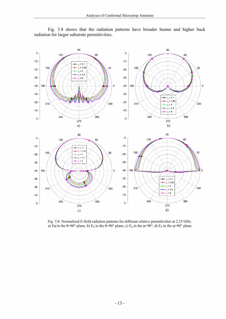
Fig. 3.8 shows that the radiation patterns have broader beams and higher back radiation for larger substrate permittivities.
a)
b)
c)
d)
Fig. 3.8: Normalized E-field radiation patterns for different relative permittivities at 2.25 GHz. a) Eφ in the θ=90° plane, b) Eθ in the θ=90° plane, c) Eφ in the φ=90°, d) Eθ in the φ=90° plane

Analyses of Conformal Microstrip Antennas
- 14 -
3.1.1.3.Substrate Thickness Variation Analysis
Another important factor in the antenna performance is the substrate thickness. Already small differences can affect considerably the bandwidth while the radiation patterns are nearly not affected. The thickness of the substrate is critical for the conformal antenna manufacture since the flexibility of the material is worse for thick substrates and very thin materials may be too fragile to bend.
As for planar antennas, the RL and AR bandwidth are increased when the substrate thickness is increased, as shown in Figs. 3.9 and 3.10 respectively. It can also be seen from Fig. 3.9 that varying the thickness causes a shift of the resonance frequency.
Fig. 3.9: Return loss for different substrate thickness
Fig. 3.10: Axial ratio for different substrate thickness

Analyses of Conformal Microstrip Antennas
- 15 -
Fig. 3.11 shows that the radiation patterns are not apparently influenced by substrate thickness variation.
a)
b)
c)
d)
Fig. 3.11: Normalized E-field radiation patterns for different substrate thickness at 2.25 GHz. a) Eφ in the θ=90° plane, b) Eθ in the θ=90° plane, c) Eφ in the φ=90°, d) Eθ in the φ=90° plane

Analyses of Conformal Microstrip Antennas
- 16 -
3.1.2. Cylindrical Microstrip Antenna Analyses for Small Radii
As commented previously, the simulations for small radii are performed with the Ansoft HFSSTM simulation tool which is based on full-wave analysis. These simulations provide a better insight into the behavior of cylindrical antennas for strongly curved surfaces. In APPENDIX B, there is a comparison of simulation results from both electromagnetic simulation tools CYLINDRICAL and HFSSTM.
In addition, in the end of this section, two examples from the literature are
commented, which complete the study of cylindrical antennas for small radii.
In these simulations, the dimensions of the cylindrical antenna are approximately the same as the reference antenna from section 3.1.1, with the difference that for small radii the size of the antenna does not correspond exactly with the one of the planar since the effects of the curvature are more significant. As example, Fig. 3.12 shows the RL for the reference antenna, which has 250 mm radius, and for the corresponding cylindrical antenna (with exactly the same dimensions) for 40 mm radius. It can be observed that the center frequency is shifted.
Fig. 3.12: Return loss for the reference antenna dimensions for 250 mm and 40 mm radius

Analyses of Conformal Microstrip Antennas
- 17 -
Hence, the patch dimensions and probe position must be optimized to obtain the corresponding center frequency and CP. The antenna is analyzed with a radius variation from 40 mm to 250 mm (1.8755 λ0 to 0.3001 λ0). The patch is placed with the boresight direction along the y-axis, being the axial length of the cylinder in the z-axis, as in the previous Fig. 3.1. In Fig. 3.13 it can be observed that the effect of the radii has a similar behaviour as for large radii although it is more significant. For the small radius 40 mm the E-field value in the extremes of the upper hemisphere is approximately 10 dB, as shown in Fig. 3.13b, and the back radiation is much larger than for larger radii, as shown in Fig. 3.13c. It must be noticed that these simulations are performed using FEM analysis and they are closer to reality than the ones using the cavity model. The comparison between FEM and cavity model analyses can be found in APPENDIX B.
a)
b)
c)
d)
Fig. 3.13: Normalized E-field radiation patterns for different small radii at 2.25 GHz.
a) Eφ in the θ=90° plane, b) Eθ in the θ=90° plane, c) Eφ in the φ=90°, d) Eθ in the φ=90° plane.

Analyses of Conformal Microstrip Antennas
- 18 -
As mentioned above, for small radii the patch dimensions are not exactly the corresponding ones in planar design. In reference [4] there is an analysis of a cylindrical antenna, shown in Fig. 3.14, with the following features: relative permittivity εr = 2.62, substrate thickness h = 0.159 cm and straight edge length 2b = 4.14 cm. This example has similar characteristics than the reference antenna in section 3.1.1 and therefore, provides results that might complete the study of this section.
Fig. 3.14: Geometry of the cylindrical microstrip antenna
In Fig. 3.15, the dependence of the optimal aspect ratio of the patch on the curvature radius is shown. The aspect ratio can be defined as the length of the patch divided by its width (a = (R + h) φ’/ b), being optimal for the minimum AR. It can be observed that there is a slightly difference in the aspect ratio for small radii and when the radius increases, the optimal aspect ratio decreases. Instead, when the radius is approximately bigger than 40 cm (or about 3λ0), the curvature does not affect the aspect ratio, being constant and the same as for the planar case. It must be noticed that for other patch dimensions this critical curvature radius may be different.
Fig. 3.15: Aspect ratio versus radius of the curved patch

Analyses of Conformal Microstrip Antennas
- 19 -
The VSWR versus the feed position on the diagonal of the patch has been also studied in [4]. As known from non-conformal antenna design, the VSWR is very sensitive to the feed position, although by varying the probe position along the diagonal, the 3-dB AR bandwidth, optimal aspect ratio and the center frequency are found to remain unchanged. In this example, within the 3-dB AR bandwidth, the VSWR is quite stable and shows fairly good matching condition, obtaining values between 1 and 1.5 [4].
From the previous example the circular polarization (CP) bandwidth for the antenna in Fig. 3.14 for the aspect ratio in Fig. 3.15 can be examined. In Fig. 3.16 is illustrated the 3 dB AR bandwidth versus different curvature radii. From 5 cm to 50 cm radius the bandwidth is only varied in 1 MHz so it can be said that the CP bandwidth is almost not affected by the curvature of the patch [4].
Fig. 3.16: 3-dB AR bandwidth versus radius of the curved patch
In reference [14], a strong dependence of the cross-polarization decoupling (XPD) on
the cylinder radius is proved. XPD is defined as the ratio of the maximum magnitude of the co-polarized field to the maximum magnitude of the cross-polarized field in a specific plane [21]. In this case, the cylindrical antenna is designed for linear polarization. Several radii have been analyzed and the result is better XPD for large radii, although the values for small radii can be considered acceptable for CP. In addition, the example shows the XPD for different resonant frequencies, proving that the patch with lower resonant frequency has a better XPD, i.e. higher XPD.

Analyses of Conformal Microstrip Antennas
- 20 -
3.2. Conformal Antennas on Doubly Curved Surfaces
The next step regarding the study of conformal antennas is to analyze doubly-curved antennas which provide additional degrees of freedom in the design. These geometries are conformed in other directions than the curvature of a cylinder and may lead to more elaborate solutions. Due to their higher complexity, arbitrary conformal antennas on doubly curve surfaces are difficult to analyze and there are fewer references available [14-18]. One of the important parameters to be taken into account in these geometries is the polarization. Since they have two curvatures, the effects commented in section 3.1.2 are twice for these structures.
One of the most interesting features of conformal antennas on doubly curved surfaces
is the nearly full hemispherical coverage and more possibilities for aerodynamic designs. The following sections provide an insight into this type of antennas considering the radiation pattern characteristics and polarization. The first geometry presented, the sphere, is the most common antenna on doubly curve surfaces. The other geometry introduced, the torus, is a new type of antenna. No references were found about the use of this geometry for conformal antennas.
3.2.1. Spherical Microstrip Antenna
The radius variation for spherical microstrip antennas will determine the curvature of the patch in both elevation and azimuth directions. The radius of doubly curved surfaces has a much larger impact on the resonant frequency than of singly curved surfaces [15]. An expected effect is a broader beam in the elevation plane, as well as in the azimuth plane. Therefore, a better hemispherical coverage is expected through this kind of structure. The geometry of the spherical microstrip antenna is illustrated in Fig. 3.17. The quasi-square patch is employed for the analyses in the next sections. However, patches with different shapes can be printed on the sphere, like a rectangular, an annular ring or a wraparound antenna, as presented in [16].
Fig. 3.17: Geometry of the quasi-square spherical microstrip antenna

Analyses of Conformal Microstrip Antennas
- 21 -
As commented previously, the polarization of doubly curved antennas is an important factor to be considered. Usually, polarization characteristics are referenced to a particular coordinate system. Three alternative definitions are adopted by Ludwig [23], illustrated in Fig. 3.18. The first definition is referred to a rectangular coordinate system, the second one to a spherical coordinate system, using the unit vectors tangent to the spherical surface, and the last definition is described as what one measures when the antenna patterns are taken in the usual manner [23]. For cylindrical antennas, usually the cylinder axis (z in Fig. 3.1) coincides with the vertical axis of the coordinate system (polarization reference axis). For more generally shaped conformal antennas, the choice of coordinates is not so evident. The polarization concept adopted in this project for spherical antennas refers to the most common definition, number 2 in Fig. 3.18, of the Ludwig definitions. It was mentioned in the previous section that the XPD of cylindrical antennas is worse than their planar counterparts due to the curvature effects. Therefore, for doubly curved surfaces this effect is even more significant since there is one additional curvature. For array configurations, the curvature is very important to be taken into account since when the radiating elements are almost free of cross polarization, the curvature of the structure can produce cross polarization.
Fig. 3.18: Polarization definitions according to Ludwig [23]

Analyses of Conformal Microstrip Antennas
- 22 -
3.2.2. Toroidal Microstrip Antenna The geometry of the toroidal antenna is presented in Fig. 3.19. This doubly-curved antenna has two different radii that vary the curvature of the patch. The radius of the bent cylinder is referred to as inner radius and the radius of the torus ring is referred to as torus radius, considering the torus radius from the center of the ring to the center of the bent cylinder. The torus radius must be always equal or smaller than the inner radius. As for spherical microstrip antennas, the shape of the patch printed on the torus can vary. A very interesting geometry is the wraparound patch, which provides exceptionally broad radiation patterns. This new type of antenna has been proposed as a result of the current work.
Fig. 3.19: Geometry of the quasi-square toroidal microstrip antenna
3.3. General Characteristics of Conformal Antennas Compared with their Planar Counterparts
The different antennas investigated in this section are analyzed in order to provide a better understanding of how the performance, mainly the radiation characteristics, depends on the shape of the conformal antennas.
The study is divided into two parts, separating quasi-square and wraparound patches. In each part, antennas with the same resonance frequency are printed on different geometries in order to achieve reasonable results for the comparison of the different structures.
3.3.1. Quasi-square Conformal Microstrip Antennas The initial quasi-square patch is designed for RHCP with single probe feeding, at the
frequency of 2.25 GHz as for the previous analyses. The substrate has a relative permittivity εr = 2.55, a loss tangent of tg δ = 0.0022 and a thickness of h = 3.048 mm. The planar case is compared with the conformal structures mentioned in the last sections, all illustrated in Fig. 3.20. In order to obtain a coherent comparison, the curvatures of the conformal structures have all 0.3λ0 radius (4 cm for 2.25 GHz), maintaining the same resonant frequencies. As the toroidal antenna has two different radii, it is designed for a patch curvature of 0.3λ0 in the azimuth plane and 0.15λ0 in the elevation plane. In order to achieve this geometry, both inner and torus radii are 0.15λ0. This is due to the fact that the torus radius goes from the center of the ring to the center of the bent cylinder as mentioned before. Therefore, the actual curvature of the patch in the azimuth plane is the torus radius plus the

Analyses of Conformal Microstrip Antennas
- 23 -
inner radius, i.e. 0.3λ0. As commented in section 3.1.2, the design of a patch on conformal structures with small radii differs from the planar approach. In doubly curved surfaces this variation is even increased. Therefore, the antennas analyzed in this section are first designed with a rough approximation of the planar case and after that optimized for the operational frequency with the simulation tool HFSSTM.
a) Planar b) Cylindrical c) Spherical d) Toroidal
Fig. 3.20: Conformal antennas and their planar counterpart simulated in HFSSTM
The comparison of the E-field radiation patterns can be seen in Fig. 3.21. As expected, the planar antenna presents the narrowest beam. In the φ = 0º plane, shown in Fig. 3.21a, the radiation from the doubly curved geometries is broader since there is a curved surface where for the singly curved geometries it is straight. Usually, singly curved geometries are theoretically analyzed with infinite ground plane, i.e. infinite long cylinders in the case of cylindrical antennas. In the elevation plane these antennas are considered as infinite planar antennas, not allowing back radiation and presenting very narrow beamwidth. In the θ = 90º plane all analyzed conformal antennas have the same curvature of 0.3λ0. That leads to approximately the same beamwidth in the hemisphere of maximum radiation, as illustrated in Fig. 3.21b.
a) φ = 0° plane b) θ = 90° plane
Fig. 3.21: Normalized E-field radiation patterns for different antenna geometries at 2.25 GHz
Analyses of Conformal Microstrip Antennas
- 24 -
Therefore, it has been seen that the geometry of the antenna affects considerably its radiation characteristics. It must be noticed that this analysis is for the frequency 2.25 GHz, and for lower frequencies the patch, maintaining the same radius of 4 cm, would have larger dimensions and consequently the differences in the radiation patterns among the diverse geometries would be more distinguished. 3.3.2. Wraparound Conformal Microstrip Antennas: Omnidirectional Radiation
Patterns
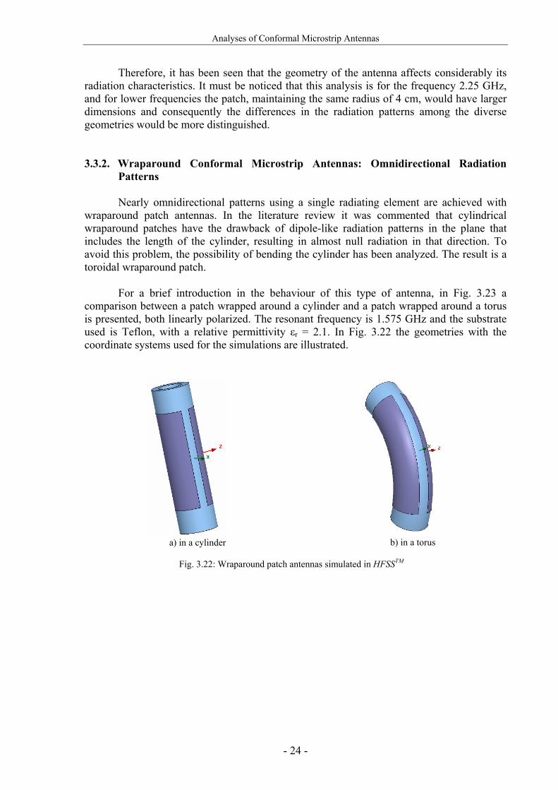
Nearly omnidirectional patterns using a single radiating element are achieved with wraparound patch antennas. In the literature review it was commented that cylindrical wraparound patches have the drawback of dipole-like radiation patterns in the plane that includes the length of the cylinder, resulting in almost null radiation in that direction. To avoid this problem, the possibility of bending the cylinder has been analyzed. The result is a toroidal wraparound patch.
For a brief introduction in the behaviour of this type of antenna, in Fig. 3.23 a
comparison between a patch wrapped around a cylinder and a patch wrapped around a torus is presented, both linearly polarized. The resonant frequency is 1.575 GHz and the substrate used is Teflon, with a relative permittivity εr = 2.1. In Fig. 3.22 the geometries with the coordinate systems used for the simulations are illustrated.
a) in a cylinder
b) in a torus
Fig. 3.22: Wraparound patch antennas simulated in HFSSTM

Analyses of Conformal Microstrip Antennas
- 25 -
Both type of antennas have similar radiation patterns in the φ = 0º plane, providing nearly omnidirectional coverage as shown in Fig. 3.23a. As commented before, in the θ = 90º plane the cylindrical antenna has dipole-like radiation pattern while the toroidal one presents nearly omnidirectional coverage.
a) φ = 0° plane b) θ = 90° plane
Fig. 3.23: Normalized E-field radiation patterns for the wraparound patch antenna on a cylinder and on a torus
at 1.575 GHz
3.4. Advantages and Disadvantages of Employing Conformal Antennas From the study on conformal antennas made in this section, the characteristics
mentioned in the overview made in section 2 have been proved. In addition, other advantages and also disadvantages have been found through this study.
It was commented earlier that conformal antennas can achieve several geometries, as
shown during the study. This ability of varying their shape to be adjusted to the contour of different vehicles improves also other considerations than EM; for example mechanical, aerodynamic or hydrodynamic. As they are structurally integrated there is no need of conventional radomes as non-conformal antennas require when they are incorporated on non-planar structures. In addition, their radar cross section (RCS) can be much lower than for their planar counterparts. For some particular cases, the physical size of certain antennas could be much smaller than in the planar case, for instance the toroidal antenna introduced in section 3.3.2, when it is designed for high frequencies is relatively smaller compared to other microstrip antennas of the same frequency range.
Regarding the antenna performance, by varying the shape of the conformal antennas
the gain can be controlled, being possible to reach nearly omnidirectional coverage while with planar antennas the almost full coverage is limited to approximately ± 60°. This very broad beam radiation patterns with non-conformal antennas can be only achieved with array configurations. In addition to the advantage of using only one antenna for the same purpose, the ripple in the radiation patterns will be considerably reduced.

Analyses of Conformal Microstrip Antennas
- 26 -
Obviously, conformal antennas have not only advantages and the drawbacks must be also mentioned. A major disadvantage is the increased complexity and cost in manufacturing of arbitrary conformal antennas. In addition, their size is restricted when package of electronics is desired since they can not be included in strongly curved structures.
The technology of conformal antennas is not fully established as for the planar ones,
being many of their analysis tools still in development, as have been seen in the literature review in section 2.1.
From the previous study was found that for very large radii, conformal antennas can
be considered for simplification as planar ones, being consequently their performance very similar to them. Instead, for small radii planar design techniques can not be applied and the designed rules are not established. In addition, circular polarization is more difficult to achieve in curved structures with the inconvenient that the maximum values of XPD are lower than for their planar counterparts. Nevertheless, those values are still acceptable for circular polarization.
Through this section conformal antennas have shown relevant advantages, especially
when very broad-beam radiation is desired or when other requirements than EM are needed. As summary, table 3.1 shows the main advantages and disadvantages commented in this section. TABLE 3.1: ADVANTAGES AND DISADVANTAGES OF CONFORMAL ANTENNAS COMPARED TO
PLANAR ONES
Advantages Disadvantages
Broad beam radiation patterns
Technology in development
Single antenna for omnidirectional
radiation applications
Amplitude and phase calculations more complicated
Gain controlled with the shape
More difficult to achieve circular polarization
Structurally integrated. Improvement of
aerodynamic profiles
Complexity and cost of manufacture
No conventional radome
required
Size restriction for packaging of electronics
Lower RCS

The Quasi-omnidirectional Toroidal Microstrip Antenna
- 27 -
4. THE QUASI-OMNIDIRECTIONAL TOROIDAL MICROSTRIP ANTENNA
The toroidal microstrip antenna is a new type of antenna with quasi omnidirectional
radiation patterns. This finding is the outcome of adding a further curvature to a microstrip antenna conformed on a cylinder. The resulting antenna is an almost wrapped patch around a torus, as shown in Fig. 4.1. The main advantage of this conformal antenna is the very broad radiation patterns (nearly omnidirectional) which are usually achieved with more than a single radiator.
There are mainly two motivations why the toroidal antenna is analyzed in more detail.
Firstly, its attractive radiation patterns that placed on the aircraft footprint might provide a nearly full hemispherical coverage. Secondly, it was preferred because there is not research found about this geometry, unlike the rest of geometries studied, and the analysis of this structure could be interesting not only for this project but also for other possible applications with omnidirectionality required.
4.1. ARINC Specifications for the ANSTASIA project
This section describes some of the relevant specifications of the passive antenna, set by ARINC (Aeronautical Radio Inc.). These are the basic specifications for the antenna studies carried out in the scope of the project ANASTASIA. The antenna should operate at the GALILEO frequency bands E5 (1164 - 1214 MHz) and L1 (1563 – 1587 MHz). The VSWR presented by the antenna to a single 50 ohm transmission line should not exceed 1.9:1 over the frequency range. The radiation pattern of the installed antenna should provide nearly omnidirectional upper hemispherical coverage and be predominantly RHCP. These specifications are showed in table 4.1. The antenna should be placed on the fuselage of an aircraft. The fuselage footprint is described in section 5.1, where the analyses concerning the effects caused by the footprint on the antenna radiation patterns are performed.
TABLE 4.1: ARINC SPECIFICATIONS
Antenna Parameter Specification
Frequency bands E5 and L1
Radiation Upper hemisphere
Polarization RHCP
VSWR 1.9:1
The Quasi-omnidirectional Toroidal Microstrip Antenna
- 28 -
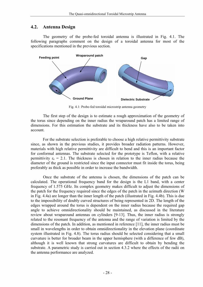
4.2. Antenna Design The geometry of the probe-fed toroidal antenna is illustrated in Fig. 4.1. The
following paragraphs comment on the design of a toroidal antenna for most of the specifications mentioned in the previous section.
Fig. 4.1: Probe-fed toroidal microstrip antenna geometry
The first step of the design is to estimate a rough approximation of the geometry of the torus since depending on the inner radius the wraparound patch has a limited range of dimensions. For this estimation the substrate and its thickness have also to be taken into account. For the substrate selection is preferable to choose a high relative permittivity substrate since, as shown in the previous studies, it provides broader radiation patterns. However, materials with high relative permittivity are difficult to bend and this is an important factor for conformal antennas. The substrate selected for the prototype is Teflon, with a relative permittivity εr = 2.1. The thickness is chosen in relation to the inner radius because the diameter of the ground is restricted since the input connector must fit inside the torus, being preferably as thick as possible in order to increase the bandwidth.
Once the substrate of the antenna is chosen, the dimensions of the patch can be calculated. The operational frequency band for the design is the L1 band, with a center frequency of 1.575 GHz. Its complex geometry makes difficult to adjust the dimensions of the patch for the frequency required since the edges of the patch in the azimuth direction (W in Fig. 4.4a) are longer than the inner length of the patch (illustrated in Fig. 4.4b). This is due to the impossibility of doubly curved structures of being represented in 2D. The length of the edges wrapped around the torus is dependent on the inner radius because the required gap angle to achieve omnidirectionality should be maintained, as discussed in the literature review about wraparound antennas on cylinders [9-13]. Thus, the inner radius is strongly related to the resonant frequency of the antenna and the range of variation is limited by the dimensions of the patch. In addition, as mentioned in reference [11], the inner radius must be small in wavelengths in order to obtain omnidirectionality in the elevation plane (coordinate system illustrated in Fig. 4.8). The torus radius should be selected considering that a small curvature is better for broader beam in the upper hemisphere (with a difference of few dB), although it is well known that strong curvatures are difficult to obtain by bending the substrate. A parametric study is carried out in section 4.3.2 where the effects of the radii on the antenna performance are analyzed.
Feeding point Wraparound patch
Ground Plane
Gap
Dielectric Substrate

The Quasi-omnidirectional Toroidal Microstrip Antenna
- 29 -
For simplicity, the initial simulations are performed with probe feeding. In order to obtain RHCP, first two probes are placed in the central lines of the patch to find the matching points. Then, they are both replaced by only one probe in approximately the same position from the edges. Finally, it is shifted around this point in order to find the optimal position to generate RHCP. Microstripline feeding, shown in Fig. 4.3, is also analyzed. Its manufacture is easier in this structure since inside the torus there is not need to include the input connector. In addition, the disappearance of the input connector inside the structure provides the possibility to increase the thickness of the substrate to improve the bandwidth.
In order to design the micrcostripline, first its width is calculated based on the planar case, as shown in Fig. 4.2. The width obtained is optimized with the simulation tool since the curvature of the microstripline affects the characteristic impedance.
Fig. 4.2: Microstrip transmission line parameters
Equation (4.1) gives the impedance value of a microstripline [24] and can be solved to find the width for a 50Ω characteristic impedance. This formula is valid for the ranges: 0.1 < W/H < 3.0; 1 < εr < 15.
ohms 8.0
98.5ln41.1
870 ⎟
⎠⎞
⎜⎝⎛
++=
TWHZ
rε (4.1)
, where W is the microstripline width and T the thickness, and εr is the substrate relative permittivity with a thickness H.
By using the parameters from the probe-fed torus T = 0.2 mm and H = 4 mm, the
microstripline is excessively wide. For this reason in the first test, the toroidal antenna is matched for an input impedance of approximately 100Ω. It can be seen in Fig. 4.3a how the feeding point is nearer the edge of the patch since it is matched to higher impedance than 50 Ω. In this case, an external impedance transformer should be used. In order to reduce the microstripline width, the substrate thickness is also reduced. Thus, for H = 1 mm, the computed width is W = 2.3 mm and in this case the input impedance is 50Ω. The feeding point is approximately the same as for the probe.
a) H = 4 mm, W = 3 mm
b) H = 1 mm, W = 2.3 mm
Fig. 4.3: Microstripline-fed toroidal microstrip antenna geometry
W
H T
εr

The Quasi-omnidirectional Toroidal Microstrip Antenna
- 30 -
Other feeding techniques may be applied to improve the performance (see APPENDIX A.1). For instance, aperture-coupled stripline-feeding might improve the bandwidth of the antenna. In this type of radiator, the inner radius is always relatively small what implies thin substrates. Hence, this feeding technique might be employed by a cautious design.
After all these considerations, the prototype antenna designed has the following dimensions, illustrated in Fig. 4.4. The outer length of the toroidal grounded substrate is L = 9.292 cm, and of the patch is W = 7.129 cm. The angular gap α = 32.872° is in length 0.602 cm. The torus radius R, shown in Fig. 4.4b, is 5 cm. The probe is placed φ = 21° from the centre of the patch on the inner curve of the torus, or 1.448 cm, and θ = 54° up from the previous point, or 0.989 cm in length, as illustrated in Fig. 4.4b. The inner radios of the torus is a = 1.05 cm and the thickness of the substrate is h = 0.4 cm. Thus, the radius b shown in Fig. 4.4c is 0.65 cm. A summary of all the dimensions is presented in table 4.2.
a) Lengths and gap
b) Torus radius and probe position
c) Inner radius and substrate thickness
Fig. 4.4: Dimensions of the toroidal microstrip antenna prototype

The Quasi-omnidirectional Toroidal Microstrip Antenna
- 31 -
TABLE 4.2: DIMENSIONS OF THE TOROIDAL MICROSTRIP ANTENNA PROTOTYPE
Parameter Value L 9.2921 cm
W 7.1294 cm
α 32.872° (0.6024 cm)
φ 21° (1.4478 cm)
θ 54° (0.9896 cm)
R 5 cm
a 1.05 cm
b 0.65 cm
h 0.4 cm
4.3. Simulation Results
The performance of the toroidal microstrip antenna is presented in this section. All
the simulations are carried out with the simulation tool HFSSTM. In addition, in the end of this section there is a parametric study that provides a better insight into this new structure.
4.3.1. Toroidal Microstrip Antenna Performance As commented in previous sections, this antenna has almost omnidirectional radiation
patterns. This can be seen in Fig. 4.5, which represents the normalized E-field in the two main planes. In the θ = 90º plane, Fig. 4.5b, the omnidirectionality is approximately 5 dB and in the φ = 0º plane illustrated in Fig. 4.5a, it is only 2 dB. Other important characteristic is the smooth radiation patterns. Usually, when arrays are used for omnidirectionality coverage purpose, the ripple in the radiation patterns is a problem to consider.

The Quasi-omnidirectional Toroidal Microstrip Antenna
- 32 -
a) φ = 0° plane
b) θ = 90° plane
Fig. 4.5: Normalized E-field radiation patterns for the probe-fed toroidal microstrip antenna at 1.575 GHz
In the next figure, Fig. 4.6, the RL is illustrated. The central frequency of this antenna
is 1.575 GHz with a bandwidth of around 155 MHz, approximately 11%. The scope of this design is not a broadband antenna since techniques presented in APPENDIX A can be applied for this purpose. Thus, the bandwidth has not been considered carefully, although all the frequencies of operation in L1, even wider bandwidth, have a RL of less than -10 dB.
Fig. 4.6: Return loss for the probe-fed toroidal microstrip antenna

The Quasi-omnidirectional Toroidal Microstrip Antenna
- 33 -
The antenna was designed for RCHP and the result of the AR is shown in Fig. 4.7. It can be seen that the AR has an acceptable value for a large part of the upper hemisphere, considering that the antenna has RHCP for hemispherical coverage.
a) φ = 0º plane
b) θ = 90° plane
Fig. 4.7: Axial ratio for the probe-fed toroidal microstrip antenna in the upper hemisphere
In the 3D-view of the radiation patterns illustrated in Fig. 4.8, it can be seen that the omnidirectinoality of the total antenna radiation is around 6 dB. A small asymmetry due to the probe position can be observed.
Fig. 4.8: 3D-view of the normalized E-field radiation patterns for the probe-fed toroidal microstrip antenna at
1.575 GHz

The Quasi-omnidirectional Toroidal Microstrip Antenna
- 34 -
Also simulation results for the microstripline-fed toroidal antenna are shown in this section. The results correspond to the torus with 4 mm thickness presented in Fig. 4.3a.
The radiation patterns in the azimuth and elevation planes maintain the particular characteristic of this antenna, the omnidireciontality. In Fig. 4.9 can be observed that the omnidirectionality is around 4 dB.
a) φ = 0° plane
b) θ = 90° plane
Fig. 4.9: Normalized E-field radiation patterns for the microstripline-fed toroidal microstrip antenna at 1.575 GHz
The RL bandwidth shown in Fig. 4.10 is approximately 155 MHz, as in the probe-fed
design.
Fig. 4.10: Return loss for the microstripline-fed toroidal microstrip antenna

The Quasi-omnidirectional Toroidal Microstrip Antenna
- 35 -
As motioned before, for the 4 mm thickness torus the microstripline was designed for higher impedance than 50 Ω. Thus, the matching point was found nearer the edges of the patch and, consequently, the CP is affected. In Fig. 4.11 is shown the AR, which is not appropriate for RHCP in the upper hemisphere. In the boresight direction the AR is larger than the acceptable value of 3 dB.
a) φ = 0º plane
b) θ = 90° plane
Fig. 4.11: Axial ratio for the microstripline-fed toroidal microstrip antenna in the upper hemisphere When the microstripline-fed toroidal microstrip antenna has a substrate thickness of 1
mm and 50 Ω of input impedance, the matching point is found in a similar position than for the probe-feed toroidal microstrip antenna. However, the polarization is affected by the missing part of the patch due to the microstripline and its lateral spaces.
Possibly, based on the previous results, the solution for the microstripline-feeding design might be to have an input impedance between those two values analyzed in order to find a position farther from the edges and not very deep in the patch for acceptable CP.
4.3.2. Parametric Study
The parametric study provides a better understanding of the antenna behaviour. The first analyses are related to the radii of the structure. After that, parameters like substrate thickness, relative permittivity and probe position are examined.
As mentioned before, the two radii of the torus are defined as torus radius and inner radius, illustrated in Figs. 4.4b and 4.4c respectively. The former is the curvature of the torus and the latter is the radius of the called bent cylinder. In the following analyses the inner radius is always considerably smaller than the torus radius. In Fig. 4.12 is illustrated the simulation results for different torus radii. The effects on the radiation patterns are opposite for the two main planes. In Fig. 4.12a it can be observed that, in the azimuth plane, the larger the inner radius is, the broader the radiation beam becomes. On the other hand, Fig. 4.12b shows that the smaller the inner radius is, the broader the radiation beam becomes in the elevation plane. Thus, there must be a trade-off for achieving a radiation pattern with the best omnidirectionality.

The Quasi-omnidirectional Toroidal Microstrip Antenna
- 36 -
a) φ = 0° plane b) θ = 90° plane
Fig. 4.12: Normalized E-field radiation patterns for different torus radii at 1.575 GHz
The inner radius has a limited range of variation since, as mentioned in section 4.2, it
determines one length of the patch that must be adjusted for the operational frequency. As expected, there is almost no variation in the radiation patterns shown in Fig. 4.13 because the range of radii analyzed is very limited. In general, it can be observed that the behaviour is opposite to the torus radius since the radiation pattern for large radii is broader in the azimuth plane and narrower in the elevation plane.
a) φ = 0° plane b) θ = 90° plane
Fig. 4.13: Normalized E-field radiation patterns for different inner radii at 1.575 GHz
The Quasi-omnidirectional Toroidal Microstrip Antenna
- 37 -
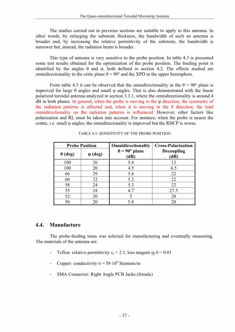
The studies carried out in previous sections are suitable to apply to this antenna. In other words, by enlarging the substrate thickness, the bandwidth of such an antenna is broader and, by increasing the relative permittivity of the substrate, the bandwidth is narrower but, instead, the radiation beam is broader. This type of antenna is very sensitive to the probe position. In table 4.3 is presented some test results obtained for the optimization of the probe position. The feeding point is identified by the angles θ and φ, both defined in section 4.2. The effects studied are omnidirectionality in the critic plane θ = 90º and the XPD in the upper hemisphere.
From table 4.3 it can be observed that the omnidirectionality in the θ = 90º plane is improved for large θ angles and small φ angles. That is also demonstrated with the linear polarized toroidal antenna analyzed in section 3.3.1, where the omnidirectionality is around 4 dB in both planes. In general, when the probe is moving in the φ direction, the symmetry of the radiation patterns is affected and, when it is moving in the θ direction, the total omnidirectionality on the radiation patterns is influenced. However, other factors like polarization and RL must be taken into account. For instance, when the probe is nearer the centre, i.e. small φ angles, the omnidirecionality is improved but the RHCP is worse.
TABLE 4.3: SENSITIVITY OF THE PROBE POSITION
Probe Position
θ (deg) φ (deg)
Omnidirectionality θ = 90º plane
(dB)
Cross-Polarization Decoupling
(dB) 100 26 5.4 13 100 20 4.5 6.5 66 29 5.6 22 60 22 5.2 22 58 24 5.3 22 55 18 4.7 27.5 52 20 5 28 50 20 5.8 20
4.4. Manufacture
The probe-feeding torus was selected for manufacturing and eventually measuring. The materials of the antenna are:
- Teflon: relative permittivity εr = 2.1, loss tangent tg δ = 0.01 - Copper: conductivity σ = 58·106 Siemens/m
- SMA Connector: Right Angle PCB Jacks (female)

The Quasi-omnidirectional Toroidal Microstrip Antenna
- 38 -
Dejar espacio aki para explicar manufacture the toroidal microstrip antenna The manufacture of this antenna might be done by two different methods.
- (melting copper) -teflon cylinder, etc... -manufacture (de la esferica y multilayer) ¿???? -explicar q tb se simulo con capa finita del material de -copper

Effects of the Aircraft Footprint
- 39 -
5. EFFECTS OF THE AIRCRAFT FOOTPRINT
An essential factor to keep in mind is the environment in which these antennas should operate. Therefore, after the previous analyses of different conformal antennas, the most promising structures are analyzed taking the aircraft footprint into account. The surface of the aircraft where the antenna must be mounted affects the radiation properties and it is important to be able to predict such variations. Complex geometries lead to elaborate problems and long-time EM simulations. Therefore, the antennas are placed on an aircraft footprint to predict the E-field radiation instead on a complete aircraft where they could be also affected by multipath effects from, for example, the wings of the aircraft.
The first part of this section explains the position of the antenna on the aircraft and
the dimensions of the footprint provided by ARINC. The next section shows the simulation results when the antennas studied previously are placed on the aircraft footprint.
5.1. Position on the Aircraft The antenna might be located on the forward part of the fuselage (or close to the
centreline), as shown in Fig. 5.1, to minimize shadowing by the vertical stabilizer, wing multi-path and shadowing by the wing during all manoeuvres.
Fig. 5.1 also illustrates the aircraft footprint dimensions. The radius of the footprint is R = 2.438 m, the straight edge is 2.134 m and the curved edge is 1.219 m. The circular cavity where the antenna should be placed has 6.35 cm radius and 1.905 cm height.
Fig. 5.1: Antenna evaluation ground plane and position on the aircraft

Effects of the Aircraft Footprint
- 40 -
5.2. Simulation Results
The structures studied previously are now analyzed on the aircraft footprint. In this case, the antennas analyzed in section 2 are redesigned for the frequency of 1.575 GHz. From Fig. 5.2, the small size of the toroidal microstrip antenna compared to the planar one and the other conformal antennas operating in the same frequency can be observed.
The antennas are integrated on the footprint in mostly three positions: along the
footprint surface, 6.5 cm over the footprint and with an absorber below the antenna. Fig. 5.2 shows the antennas on the footprint with their respective coordinate systems adopted on the EM simulations.
a) Planar
b) Cylindrical
c) Spherical
d) Toroidal Fig. 5.2: Position of the conformal antennas on the aircraft footprint for the HFSSTM simulations

Effects of the Aircraft Footprint
- 41 -
Fig. 5.3 shows the radiation patterns when the different antennas are placed along the aircraft surface. The planar and the cylindrical antennas have at least one straight edge that is along the surface of the aircraft. Instead, the doubly curved structures have very small radii and therefore, only the top of the antenna is on the aircraft surface, having the edges inside the cavity, when the antennas do nt stand out from the footprint. The results illustrated in Fig. 5.3 show that the effect in this position is similar to all the structures, having even slightly narrower beams for the doubly curved surfaces, as shown in Fig. 5.3b.
a) φ = 0° plane b) θ = 90° plane
Fig. 5.3: Normalized E-field radiation patterns for different structures placed along the footprint surface
at 1.575 GHz In the next experiment, the antenna under test is placed 6.5 cm (≈ λ0/3) over the
footprint. The distance can not be very large since the aircraft has aerodynamic features that must be maintained. Doubly curved antennas have significant back radiation that is reflected on the footprint and affects the polarization and radiation characteristics. For instance, all radiation patterns in the θ = 90º plane are rather similar, as shown in Fig. 5.4b, while without footprint the broader beams can significantly noticed. The toroidal antenna is specially affected by the footprint, radiating the narrowest beam in the θ = 90º plane.
a) φ = 0° plane b) θ = 90° plane
Fig. 5.4: Normalized E-field radiation patterns for different structures placed 6.5 cm over the footprint
at 1.575 GHz

Effects of the Aircraft Footprint
- 42 -
As last test, the antenna has an absorber below to avoid the reflections from the metallic footprint. This helps the antennas with significant back radiation to reduce the effects on the polarization and radiation characteristics. In Fig. 5.5 can be observed that the spherical and the toroidal antenna have the broader beams, although particularly the toroidal antenna is very affected in the θ = 90º plane, shown in Fig. 5.5b. It must be noticed that the distance between the footprint and the antenna is λ0/10 (1.9 cm). This is the minimum distance required for the simulation of an absorber in HFSSTM, called perfect match layer (PML).
a) φ = 0° plane b) θ = 90° plane
Fig. 5.5: Normalized E-field radiation patterns for different structures with an absorber below at 1.575 GHz
The best results from the simulations performed earlier are illustrated in Fig. 5.6.
Comparing the graphics, the spherical antenna placed λ0/10 over the footprint with an absorber below has the broader radiation pattern and, in addition, the absorber avoids reflections on the footprint, with the advantage that the AR is improved. The cylindrical antenna has similar results and could also be selected for the installation on the aircraft, having easier manufacture since it is a singly curved antenna.
a) φ = 0° plane b) θ = 90° plane
Fig. 5.6: Normalized E-field radiation patterns for different structures and positions on the footprint
at 1.575 GHz

Effects of the Aircraft Footprint
- 43 -
The aircraft fuselage has a very large radius (≈ 128 λ0), being almost a planar surface in the small region where the antenna should be placed. Therefore, a possible solution would be to use a planar antenna with an arbitrary radome to cover it, instead of a cylindrical antenna with the same radius as the fuselage. In this case, the expected performance is similar, with easier manufacture of the planar antenna. A conformal antenna would present significant advantages when installed as part of the fuselage when a large antenna array is employed, the footprint radius is smaller for the same antenna frequency, or when the antenna operates at lower frequency for the same radius, covering a considerably part of the aircraft footprint. In all these cases the radiation patterns might be broader as also the aircraft aerodynamic is improved without the need of a radome.
The toroidal antenna has been studied in detail in section 4. The main characteristic of
this antenna, the omnidirectionality, is extremely affected by the footprint, especially in the θ = 90º plane, as shown for instance in Fig. 5.5b where its beam is the narrowest. A possible reason why the radiation pattern is so affected could be that, although the antenna is nearly omnidirectional, the θ = 90º plane coincides with a minimum of radiation (around 6 dB), i.e. the extremes of the torus. This might cause the significant effect of the footprint on the radiation pattern. To prove that, the toroidal antenna have been simulated for different positions on the footprint, shown in Fig. 5.7. It is important to notice for the simulation results that the coordinate system orientation is different for each antenna position.
a) along the fuselage
b) around the fuselage
c) perpendicular to the fuselage
Fig. 5.7: Different positions of the toroidal microstrip antenna on the aircraft footprint for the HFSSTM
simulations
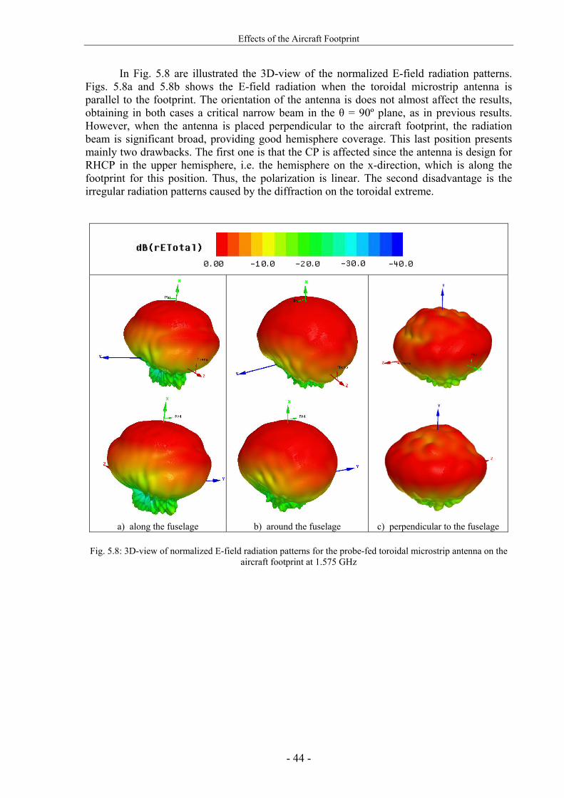
Effects of the Aircraft Footprint
- 44 -
In Fig. 5.8 are illustrated the 3D-view of the normalized E-field radiation patterns. Figs. 5.8a and 5.8b shows the E-field radiation when the toroidal microstrip antenna is parallel to the footprint. The orientation of the antenna is does not almost affect the results, obtaining in both cases a critical narrow beam in the θ = 90º plane, as in previous results. However, when the antenna is placed perpendicular to the aircraft footprint, the radiation beam is significant broad, providing good hemisphere coverage. This last position presents mainly two drawbacks. The first one is that the CP is affected since the antenna is design for RHCP in the upper hemisphere, i.e. the hemisphere on the x-direction, which is along the footprint for this position. Thus, the polarization is linear. The second disadvantage is the irregular radiation patterns caused by the diffraction on the toroidal extreme.
Fig. 5.8: 3D-view of normalized E-field radiation patterns for the probe-fed toroidal microstrip antenna on the
aircraft footprint at 1.575 GHz
a) along the fuselage b) around the fuselage c) perpendicular to the fuselage

Effects of the Aircraft Footprint
- 45 -
The last simulations have shown broader radiation beams when the antenna is perpendicular to the footprint, for linear polarization. The following simulations try to find a trade-off between the omnidirectionality and the CP. For that, the antenna is placed in four positions, shown in Fig. 5.9: along the fuselage, perpendicular to the footprint, 45º tilted from the y-axis and 60º tilted from the y-axis. It must be noticed for the simulation results that, in this case, the y-axis is the vertical one.
a) along the fuselage
b) perpendicular to the footprint
c) 45º tilted from the y-axis
d) 60º tilted from the y-axis
Fig. 5.9: Different positions of the toroidal microstrip antenna on the aircraft footprint for the HFSSTM
simulations

Effects of the Aircraft Footprint
- 46 -
Fig. 5.10 shows the simulation results for the positions mentioned above. As expected, when the toroidal microstrip antenna is nearer to the perpendicular position, the radiation beam is broader, but also has added ripple because of the diffraction commented before.
a) φ = 90° plane b) θ = 90° plane
Fig. 5.10: Normalized E-field radiation patterns for the cylindrical and the toroidal antenna on the footprint at
1.575 GHz In order to analyze the CP on these radiation patterns, table 5.1 shows the value of the XPD and the angle covered with that value on the hemisphere of radiation. The XPD obtained when the antenna is on the footprint is 10 dB (around 5 dB of AR). The CP has a larger coverage when the toroidal microstrip antenna is nearer the parallel position, as expected. The more tilted the toroidal antenna is, the less coverage of CP exists and also the more slightly asymmetry on the CP radiation.
All positions analyzed have not used any absorber below to avoid field reflections on the footprint. When an absorber is used, the XPD improves to values between approximately 15 and 20 dB.
TABLE 5.1: RHCP COVERAGE FOR DIFFERENT POSITIONS OF THE TOROIDAL MICROSTRIP ANTENNA ON THE AIRCRAFT FOOTPRINT
Antenna Position on the Aircraft
Footprint XPD (dB)
Hemisphere Angle
Coverage (deg) Parallel 10 120
Perpendicular 0 180
45° from the y-axis 10 80
60° from the y-axis 10 110

Conclusions & Future Work
- 47 -
6. CONCLUSIONS & FUTURE WORK Conclusions
Through this project, the main advantages and disadvantages of employing conformal antennas have been established. Fundamentally, the use of conformal antennas is suggested in case of very broad-beam radiation patterns are desired. The no-need of radome when using non-planar antennas for other purposes than EM is other attractive feature. The most outstanding drawback of conformal antennas is the increased complexity and cost in manufacturing. The curvature effects on the resonant frequency and polarization have been demonstrated. The conformal antennas studied have been simulated together with an aircraft footprint and the results show that the radiation patterns and polarization are very affected by the footprint. When an absorber is included below the antennas, these effects are reduced. Therefore, the integration of these antennas on aircraft is advisable when they provide broader beams than their counterparts but with limited back radiation in order not to affect the polarization characteristics, i.e. the cylindrical antenna.
The toroidal microstrip antenna has been introduced as a quasi-omnidirectional
conformal antenna. It has been proved that can be designed for CP in one hemisphere. When this antenna is integrated on aircraft, its radiation patterns are considerably affected. Some experiments on the antenna position have been performed, obtaining the conclusion that the broader beam is achieved when the antenna is perpendicular to the footprint, with a nearly full hemispherical coverage.
Future Work This project provides the opportunity of continuing the research on the toroidal microstrip antenna. The current pending patent together with the manufacture and measurement of this antenna for more realistic results will establish this antenna geometry as a possible solution for communication and navigation applications. In addition, array configurations in this new structure might be interesting to study, e.g. for beam forming in broad coverage. The feeding techniques and configurations commented in APPENDIX A could be practical to applied to this antenna for performance improvement. A deeper investigation would be to study the theoretical methods of analysis and design on this type of antenna.
Array configurations of conformal antennas would be the next step for the general
conformal antenna study. Further investigation on conformal antenna arrays might reveal additional advantages over planar ones.

- 48 -
REFERENCES [1] Vedran Azman, “Conformal Antenna Arrays for 3G Cellular Base Stations”,
Bachelor Thesis, The University of Queensland, October 2002.
[2] M. V. T. Heckler, “Circularly Polarized Microstrip Antenna Arrays Conformed on Cylindrical Surfaces”, MSc. Thesis, Instituto Tecnológico de Aeronáutica, Brazil, 2003. (in Portuguese)
[3] G. Gottwald and W. Wiesbeck, “Radiation Efficiency of Conformal Microstrip Antennas on Cylindrical Surfaces”, Antennas and Prop. Socety International Symposium, Vol. 4, pp: 1780-1783, June 1995.
[4] K.-L. Wong and S.-Y. Ke, “Cylindrical-Rectangular Microstrip Patch Antenna for Circular Polarization”, IEEE Tran. On Antennas and Prop., Vol. 41, No. 2, February 1993.
[5] W.Y. Tam, A.K.Y. Lai, and K.M. Luk, “Microstripline- and stripline-fed aperture-coupled cylindrical rectangular microstrip antennas”, IEEE Proc. –Microw. Antennas Prop., Vol. 145, No. 3, June 1998.
[6] S. Raffaelli, Z. Sipus and P.-S. Kildal, “Analysis and Measurements of Conformal Patch Array Antennas on Multilayer circular Cylinder”, IEEE Trans. on Antennas and Propagation, Vol. 53, No. 3, March 2005.
[7] S. Raffaeli, Z. Sipus, and P.-S. Kildal, “Input Impedance and Radiation Pattern of Patch on Multilayer Cylinder”, Proceedings of the Millennium Conference on Antenna and Prop., AP2000, April 2000, Switzerland.
[8] J. Ashkenazy, S. Shtrikman and D. Treves, “Electric Surface Current Model for the Analysis of Microstrip Antennas on Cylindrical Bodies”, IEEE Trans. Antennas Prop., vol. AP-33, pp. 295-300, Mar. 1985.
[9] Q. Jinghui, Z. Lingling, Du Hailong and Li Wei, “Analysis and Simulation of Cylindrical Conformal Omnidirectional Antenna”, Microwave conference Proceedings, 2005. Asia-Pacific Conference Proceedings. Vol. 4, Dec. 2005.
[10] Naftali Herscovici, Z. Sipus and P.-S. Kildal, “The Cylindrical Omnidirectional Patch Antenna”, IEEE Trans. on Antennas and Prop., Vol. 49, No. 12, Dec 2001.
- 49 -
[11] Zvonimir Sipus, Naftali Herscovici, and Davor Bonefacic, “The Circularly Polarized Cylindrical Patch”, IEEE-APS Conference on Antennas and Prop. for Wireless Com., 1998. Pages: 145-148.
[12] Radovan Zentner, Zvonimir Sipus, Naftali Herscovici, and Juraj Bartolié, “Omnidirectional Stacked Patch Antenna Printed on Circular Cylindrical Structure”, IEEE Antennas and Prop. Society International Symposium, 2002. Volume 2, Pages: 272-275.
[13] S. De Asis Fonseca and A. Giarola, “Analysis of Microstrip Wraparound Antennas using Dyadic Green’s Functions”, IEEE Trans. Antennas Prop., vol. AP-31, pp. 248-253, Mar. 1983.
[14] Kin-Lu Wong, “Design of Nonplanar Microstrip Antennas and Transmission Lines”, John Wiley & Sons, 1999.
[15] Lars Josefsson and Patrik Persson, “Conformal Array Antenna Theory and Design”, Wiley-IEEE Press, March 2006. pp. 1-5, 230-238, 265-302.
[16] K.-M. Luk and W.-Y. Tam, “Patch Antennas on a Spherical Body”, IEEE Proceedings, Vol. 138, No. 1, February 1991.
[17] Z. Sipus, N. Burum and J. Bartolic, “Moment Method Analysis of Rectangular Microstrip Antennas on Spherical Structures”, Antennas and Prop. Society International Symposium, Vol. 3A, pp. 126-129, July 2005.
[18] K.-M. Luk and W.-Y. Tam, “Analysis of Spherical-Wraparound Microstrip Antennas by Spectral Domain Method”, China 1991 International conference on Circuits and Systems, June 1991.
[19] E. A. Navarro, A. Luximon, Ian J. Craddock, Dominique L. P. and Michael Dean, “Multilayer and Conformal Antennas Using Synthetic Dielectric Substrates”, IEEE Trans. of Antennas and Propagation, Vol. 51, No. 4, April 2003.
[20] F. Lumini, L. Cividanes and J.C.S. Lacava, “Computer Aided Design Algorithm for Singly Fed Circularly Polarized Rectangular Microstrip Patch Antennas”, Int J RF and Microwave CAE, vol. 9, No. 1, pp. 32-41, Jan. 1999.
[21] Per-Simon Kildal, “FOUNDATIONS OF ANTENNAS. A Unified Approach”. Studentlitteratur, 2004. pp. 23-30, 191-214.

- 50 -
[22] C. A. Balanis, “ANTENNA THEORY. Analysis and Design”, John Wiley & Sons Inc., Second Edition, 1007. pp. 722-772.
[23] Ludwig A. C., “The Definition of Cross Polarization”, IEEE Trans. Antennas Prop., vol. AP-21, pp. 116-119, January 1973.
[24] IPC-2251, “Design Guide for Electronic Packaging Utilizing High-Speed Techniques”, 4th Working Draft, February 2001.
[25] K. Ghorbani and R.B. Waterhouse, “Dual Polarized Wide-Band Aperture Stacked Patch Antennas”, IEEE Trans. of Antennas and Prop., Vol. 52, No. 8, August 2004.
[26] W. F. Richards, Y.T. Lo and D. D. Harrison, “An Improved Theory for Microstrip antennas and applications”, IEEE Trans. of Antennas Prop., vol. 29, pp. 38-46, Jan. 1981.
[27] EWCA (European Workshop on Conformal Antennas): www.ewca-home.org/. Fig. 2.1b: www.ewca-home.org/about.html. Fig. 2.1c: www.etk.ee.kth.se/groups/tet/ewca05/index.html
[28] Ball Aerospace & Technologies Corp.: www.ballaerospace.com. Fig. 2.1a: www.ballaerospace.com./pdf/antennatech.pdf
[29] ANASTASIA European project: www.dlr.de/kn/institut/abteilungen/nl/projekte/active/anastasia/anastasia_en.html
- 51 -
ACKNOWLEDGEMENTS
I would like to thank my supervisor, Eduardo Schittler Neves, for his guidance, assistance during my master thesis and his professional advices for the future. I would also like to show my gratitude to Dr. Achim Dreher for his supervision and suggestions, and the rest of the DLR antenna department, especially Marcos Heckler for the permission to use his software CYLINDRICAL and his unconditional help, Edgar Clemens for always facilitating me the necessary work tools, Dr. Lukasz Greda and Wahid Elmarissi for his assistance in specific situations, and Vicente Pérez for supporting me on the difficult moments. Grateful thanks to Prof. Per-Simon Kildal for his remarkable antenna course which motivated me to guide my professional career to the antenna field and for the opportunity he gave me to participate in this thesis project. Thanks also to my classmates from Chalmers, especially to my friends Panagiota Lioliou and Frédéric Joerger for the great moments of studying together. I would also like to thank my family, my parents Carmen and Alicio, my brother Victor and my grandparents Carmen and José, for their affection and unconditional support in all my objectives. Last but not least, I would like to thank my boyfriend, Andreas Fabricius, for his patience, constant support and love. Thank all of you.

Fundamentals of Microstrip Antennas
- 52 -
APPENDICES A. Fundamentals of Microstrip Antennas
Only microstrip antennas will be considered for this project due to the fact that this is
the most suitable type of antennas which might be conformed over a given surface of arbitrary shape. In addition, they have other advantages as low profile, moderate gain, easy of arraying, compatible with MMIC, light weight, low cost, etc. However, it must be mentioned some disadvantages like reduced bandwidth and relatively low radiation efficiency due to the surface wave excitation and losses from the conductor and the dielectric substrate. Microstrip patch antennas consist of a thin metallic strip etched on a grounded dielectric substrate, as can be shown in Fig. A.1b, which shows a probe-fed microstrip patch antenna. The geometry of the patch can be almost any type of shape: square, rectangular, circular, triangular, etc. The properties of the substrate, such as thickness and relative permittivity, play an important role in the performance of the antenna.
The radiation from a microstrip patch antenna is equivalent to the radiation from two apertures, i.e. two equivalent magnetic currents with same direction. This equivalent model is the result of replacing the E-fields of the patch in Fig. A.1a by orthogonal magnetic currents. On the non-radiating edges the E-fields have opposite direction and, therefore, opposite magnetic currents that cancel each other.
a) b)
Fig. A.1: a) Microstrip patch antenna E-fields. b) Probe-fed microstrip patch antenna geometry A.1. Feeding Techniques
There are four fundamental techniques to feed a microstrip patch antenna [1]: edge feeding, probe feeding, aperture coupling and proximity coupling.
The former is one of the initial microstrip excitation techniques. In this method, the microstrip line is in direct contact with the patch, as shown in Fig. A.2a. The best advantage of this feeding technique is the ease of manufacture since the microstrip line and patch can be etched on the same board. However, there is an important drawback which is the undesired radiation from the feed that affects the radiation pattern of the antenna.
Radiating edges

Fundamentals of Microstrip Antennas
- 53 -
Probe feeding is a simple method where the inner conductor of a coaxial cable is extended through the ground plane and is connected to the patch, shown in Fig. A.2b. One advantage, unlike the method explained above, is the isolation of the feed from the radiating element via the ground plane. This feature minimizes the spurious radiation and makes it an efficient method since there is direct contact with the element. Nevertheless, there is still narrow bandwidth.
Next method to comment is aperture-coupling. It is the first non-contact mechanism
introduced to improve the drawbacks of the direct feeding techniques: narrow bandwidth and surface waves. In Fig. A.2c is illustrated an example of this technique. The power from the feed is coupled through a slot in the ground plane which separates the substrates of the feed and the patch. This method simplifies the fabrication and allows optimization of the feed and antenna substrates independently.
The last method introduced in this appendix, shown in Fig. A.2d, is called proximity
coupling. The microstrip line is located on the grounded substrate and the patch is etched on the top of the second substrate that is located above. The two substrates are placed in certain distance allowing power from the feed electromagnetically couple to the patch. This mechanism is capacitive in nature unlike direct contact techniques. Thus, the bandwidth usually is increased. The drawback is that this method produces high spurious feeding radiation since the feed and antenna layers are not fully independent.
a) Edge feeding
b) Probe feeding
c) Aperture coupling
d) Proximity coupling
Fig. A.2: Microstrip patch antenna feeding techniques
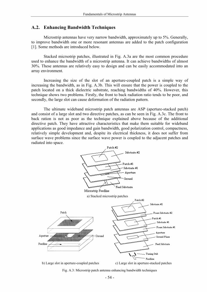
Fundamentals of Microstrip Antennas
- 54 -
A.2. Enhancing Bandwidth Techniques Microstrip antennas have very narrow bandwidth, approximately up to 5%. Generally, to improve bandwidth one or more resonant antennas are added to the patch configuration [1]. Some methods are introduced below. Stacked micrsotrip patches, illustrated in Fig. A.3a are the most common procedure used to enhance the bandwidth of a microstrip antenna. It can achieve bandwidths of almost 30%. These antennas are relatively easy to design and can be easily accommodated into an array environment. Increasing the size of the slot of an aperture-coupled patch is a simple way of increasing the bandwidth, as in Fig. A.3b. This will ensure that the power is coupled to the patch located on a thick dielectric substrate, reaching bandwidths of 40%. However, this technique shows two problems. Firstly, the front to back radiation ratio tends to be poor, and secondly, the large slot can cause deformation of the radiation pattern.
The ultimate wideband microstrip patch antennas are ASP (aperture-stacked patch) and consist of a large slot and two directive patches, as can be seen in Fig. A.3c. The front to back ration is not as poor as the technique explained above because of the additional directive patch. They have attractive characteristics that make them suitable for wideband applications as good impedance and gain bandwidth, good polarization control, compactness, relatively simple development and, despite its electrical thickness, it does not suffer from surface wave problems since the surface wave power is coupled to the adjacent patches and radiated into space.
a) Stacked microstrip patches
b) Large slot in aperture-coupled patches
c) Large slot in aperture-stacked patches
Fig. A.3: Microstrip patch antenna enhancing bandwidth techniques

Electromagnetic Analysis Tools
- 55 -
B. Electromagnetic Analysis Tools
In this appendix, the simulation tools used in the project are presented. Their methods of analysis are introduced for a better understanding of the actual results. In addition, some general recommendations when simulating are mentioned. Finally, both simulation tools are compared to prove the accuracy of their results. B.1. CYLINDRICAL: Cavity Model Analysis
CYLINDRICAL is a CAD that designs and analyzes circularly polarized probed-fed quasi-square microstrip antennas conformed on a cylinder, as can be seen in Fig. B.1, using the cavity model technique. This is a simple method of analysis that provides approximate results for a good insight into the physical behaviour of the antenna. With this method, the normalized fields within the dielectric substrate can be found by treating that region as a cavity bounded by electric conductors (patch and ground) and magnetic walls (to simulate open circuit) along the perimeter of the patch. This approximate model produces reactive input impedance and it does not radiate any power. Nevertheless, the fields generated to such a model are similar to the actual ones and thus, the radiation patterns, input impedance and resonance frequencies are close to reality. More information about the cavity model method can be found in [22].
The cavity model analysis has some few restrictions that must be taken into account. For instance, the substrate thickness must be thin in order to obtain accurate results. Other limitation is that the fields do not converge at the extremes of the cylinder, as will be shown in the last section of this appendix.
The problem mentioned in section 3.1.1.1 where small radii can not be performed is due to a final optimization of the AR in CYLINDRICAL. For small radii, the AR for the resonant frequency is difficult for optimizing since takes worse values than for large radii. Therefore, the software never finds an adequate value to show.
Fig. B.1: CYLINDRICAL simulation tool user interface
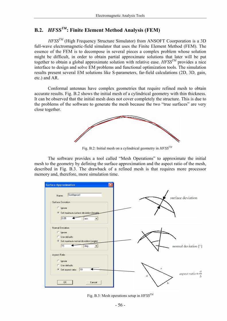
Electromagnetic Analysis Tools
- 56 -
B.2. HFSSTM: Finite Element Method Analysis (FEM)
HFSSTM (High Frequency Structure Simulator) from ANSOFT Coorporation is a 3D full-wave electromagnetic-field simulator that uses the Finite Element Method (FEM). The essence of the FEM is to decompose in several pieces a complex problem whose solution might be difficult, in order to obtain partial approximate solutions that later will be put together to obtain a global approximate solution with relative ease. HFSSTM provides a nice interface to design and solve EM problems and functional optimization tools. The simulation results present several EM solutions like S-parameters, far-field calculations (2D, 3D, gain, etc.) and AR.
Conformal antennas have complex geometries that require refined mesh to obtain accurate results. Fig. B.2 shows the initial mesh of a cylindrical geometry with thin thickness. It can be observed that the initial mesh does not cover completely the structure. This is due to the problems of the software to generate the mesh because the two “true surfaces” are very close together.
Fig. B.2: Initial mesh on a cylindrical geometry in HFSSTM
The software provides a tool called “Mesh Operations” to approximate the initial mesh to the geometry by defining the surface approximation and the aspect ratio of the mesh, described in Fig. B.3. The drawback of a refined mesh is that requires more processor memory and, therefore, more simulation time.
Fig. B.3: Mesh operations setup in HFSSTM

Electromagnetic Analysis Tools
- 57 -
B.3. Simulation Comparison
Simulation results are presented in this section to prove agreement between the software introduced previously. The main difference of these two EM simulation tools is the time consumed in the simulation process. CYLINDRICAL can simulate around 12 times faster than HFFSTM since the cavity model offers approximate results. For instance, a cylindrical structure with a refined mesh simulated in HFFSTM can last around 2 hours in a 16 GHz RAM processor while in CYLINDRICAL only lasts approximately 10 minutes.
Fig. B.4 illustrates the E-field radiation patterns for the reference cylindrical antenna analyzed in section 3.1.1. The simulations are performed in the two different simulation tools used in this project with the objective of comparing the results. As commented before, the cavity model used in CYLINDRICAL offers approximate results with very smooth radiation patterns and realistic for the radiation in the main hemisphere. Instead, the FEM used in HFFSTM is more close to the actual radiation patterns. In reference [2] measurements of the antenna are presented and shows very good agreement with these simulations. For the comparison it must be taken into account that in the cavity model the cylinder is considered infinitely long and in the FEM it has a limited height. This affects the back radiation as can be observed in Figs. B.4b and B.4d.
In conclusion, the agreement between them is very satisfactory in the hemisphere of
radiation. Only differs slightly at the extremes of the cylinder as can be observed in Fig. B.4d, due to limitation of CYLINDRICAL mentioned before.

Electromagnetic Analysis Tools
- 58 -
a)
b)
c)
d)
Fig. B.4: Normalized E-field radiation patterns at 2.25 GHz simulated in CLYINDRICAL and HFSSTM. a) Eφ in the θ=90° plane, b) Eθ in the θ=90° plane, c) Eφ in the φ=90° plane, d) Eθ in the φ=90° plane


![1880 IEEE TRANSACTIONS ON ANTENNAS AND …anagnostou.sdsmt.edu/Papers/[J22] TAP 2014, Phase-Compensated... · Phase-Compensated Conformal Antennas for Changing Spherical ... of the](https://img.pdfslide.net/doc/110x75/5ab1a1ec7f8b9a1d168ce9a7/1880-ieee-transactions-on-antennas-and-j22-tap-2014-phase-compensatedphase-compensated.jpg)