Embed Size (px)
Citation preview
International Journal of Science and Research (IJSR) ISSN (Online): 2319-7064
Index Copernicus Value (2015): 78.96 | Impact Factor (2015): 6.391
Volume 6 Issue 1, January 2017 www.ijsr.net
Licensed Under Creative Commons Attribution CC BY
Analysis of HVDC Power Transmission Line with Unique Power Control Room
Sharad Chandra Rajpoot1, Prashant Singh Rajpoot2, Kishan Gupta3, Durga Sharma4
1Assistant Professor, G.EC. Jagdalpur, Bastar, Chhattisgarh, India 2Assistant Professor, L.C.I.T., Bilaspur, Chhattisgarh, India
3Electrical Instructor Aadimjati Kalian Vibhag, Ratanpur, Bilapur, Chhattisgarh, India 4Assistant Professor C.V.R.U. Kota, Bilaspur, Chhattisgarh, India
Abstract: A high-voltage, direct current (HVDC) electric power transmission system (also called a power super highway or anelectrical super highway) uses direct current for the bulk transmission of electrical power, in contrast with the more common alternating current (AC) systems. For long-distance transmission, HVDC systems may be less expensive and suffer lower electrical losses. For underwater power cables, HVDC avoids the heavy currents required to charge and discharge the cable capacitance each cycle. For shorter distances, the higher cost of DC conversion equipment compared to an AC system may still be justified, due to other benefits of direct current links. HVDC allows power transmission between unsynchronized AC transmission systems. Since the power flow through an HVDC link can be controlled independently of the phase angle between source and load, it can stabilize a network against disturbances due to rapid changes in power. HVDC also allows transfer of power between grid systems running at different frequencies, such as 50 Hz and 60 Hz. This improves the stability and economy of each grid, by allowing exchange of power between incompatible networks.
Keywords: Power Transmission Line, Flexible AC Transmission Systems (FACTS), High Voltage Direct Current (HVDC), power system
1.Introduction
High voltage is used for electric power transmission toreduce the energy lost in the resistance of the wires. For a given quantity of power transmitted, doubling the voltage will deliver the same power at only half the current. Since the power lost as heat in the wires is proportional to the square of the current for a given conductor size, or inversely proportional to the square of the voltage, doubling the voltage reduces the line losses per unit of electrical power delivered by a factor of 4. While power lost in transmission can also be reduced by increasing the conductor size, larger conductors are heavier and more expensive. High voltage cannot readily be used for lighting or motors, sotransmission-level voltages must be reduced for end-use equipment. Transformers are used to change the voltage levels in alternating current (AC) transmission circuits. Because transformers made voltage changes practical, and AC generators were more efficient than those using DC, ACbecame dominant after the introduction of practical systems of distribution in Europe in 1891.[2]
Practical conversion of power between AC and DC becamepossible with the development of power electronics devices such as mercury-arc valves and, starting in the 1970s, semiconductor devices as thyristors, integrated gate-commutated thyristors (IGCTs), MOS-controlled thyristors(MCTs) and insulated-gate bipolar transistors (IGBT). The modern form of HVDC transmission uses technology developed extensively in the 1930s in Sweden (ASEA) and in Germany. Early commercial installations included one inthe Soviet Union in 1951 between Moscow and Kashira, and a 100 kV, 20 MW system between Gotland and mainland Sweden in 1954. The longest HVDC link in the world is the Rio Madeira link in Brazil, which consists of two bipoles of±600 kV, 3150 MW each, connecting Porto Velho in the
state of Rondônia to the São Paulo area. The length of the DC line is 2,375 km (1,476 mi) [4]
Flexible AC Transmission Systems (FACTS) technology isbased on the use of power electronic controlled devices for allowing transmission circuits to be used to their maximum thermal capability. In particular the FACTS devices aim principally to control the three main parameters directly effecting AC power transmission namely voltage, phase angle, and impedance. High Voltage Direct Current (HVDC) transmission is parallel technology using power electronics and is not normally included as a FACTS technology. [2]
1.1 Motivation and Objective
A transmission line basically consist two or more parallel conductors to connect the source to the consumer or the load. Uniform transmission line is that whose parameter doesn’t change with per unit length. Transmission line parameters are R-L-C-G.the HVDC system has followings objectives-
a)Losses is occurs in all the stages of the generation transmission and distribution. The losses at the transmission level can be mitigate by the hvdc system.
b)It can interconnect the different power system having different frequency.
c)For long distance high power transmission by over head line and underground line and for frequency conversion 60-50 hz and 50-25hz.
2. Planning for HVDC Transmission Line
HVDC projects for long-distance transmission have two (orrarely, more) converter stations and a transmission lineinterconnecting them. Generally overhead lines are used for
Paper ID: ART20164362 1465
International Journal of Science and Research (IJSR) ISSN (Online): 2319-7064
Index Copernicus Value (2015): 78.96 | Impact Factor (2015): 6.391
Volume 6 Issue 1, January 2017 www.ijsr.net
Licensed Under Creative Commons Attribution CC BY
interconnection, but important classes of HVDC projects usesubmarine power cables. A back-to-back station has notransmission line and connects two AC grids at differentfrequencies or phase counts. Historical HVDC systems usedthe Thury system of motor-generators but these have all beenmade obsolete by later developments such as mercury-arcvalves, thyristors, and IGBT power transistors.
3.Design and Modeling of Transmission Line
3.1 Introduction
An Electrical transmission line can be represented by a series combination of resistance, inductance and shunt combination of conductance and capacitance. these parameters are symbolized as R, L, G and C respectively, of these R and G are least important in the sense that they do not effect much the total equivalent impedance of the line and hence the transmission capacity.[1] They are of course very much importance when transmission efficiency and economy are tobe evaluated as they completely determine the real transmission line losses. The resistance of a conductor isgiven by
R= power loss in conductor / I2ohms 3.1
Where R is the effective resistance of the conductor and I the current flowing through the conductor. The effective resistance is equal to the D.C resistance of the conductor only if the current is uniformly distributed throughout the section of the conductor. Difference in the D.C resistance and effective resistance to frequencies less than 50 Hz is less than 1 percent for copper conductors of section less than 350,000 circular mils. The loss on the overhead transmission line is due to
1) Ohmic loss in the power conductors 2) Corona loss 3) Leakage at the insulators which support the lines at the
towers
The performance of lines is meant the determination ofefficiency and regulation of lines % efficiency = power delivered at the receiving end /power sent from the sending end *100 3.2
Regulation of a line is defined as the change in the receiving end voltage, expressed in percent of full load voltage, from no load to full load, keeping the sending end voltage and frequency constant. Expressed mathematically,
% regulation =(V!r – Vr)/Vr*100 3.3 Where V!r is the receiving end under no load condition and Vr the receiving end voltage under full load condition. It isto be noted here that V!r and Vr are the magnitudes ofvoltage.[9]
3.2 Representation of transmission lines
A transmission line is a set of conductors being run from one place to another supported on transmission towers. Such lines, therefore, have four distributed parameters, series resistance and inductance and shunt capacitance and conductance.[15] it is to be noted that the electrical power isbeing transmitted over the overhead lines at approximately the speed of light. In order to get one full wave variation ofvoltage or current on the line, the length of the line for 50 Hzsupply will be given by
f * λ = v 3.4 where f is the frequency of supply, λ is wavelength i.e the length of the in this case and v the velocity of the wave i.e the velocity of light
λ = v/f = 6000 Km 3.5
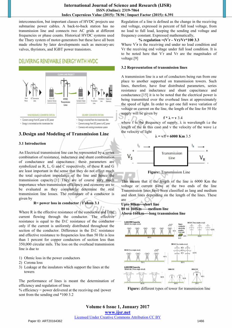
Figure: Transmission Line
This means that if the length of the line is 6000 Km the voltage or current wave at the two ends of the line Transmission lines have been classified as lang and medium and short lines depending on the length of the lines. These are Upto 80km---short line80 to 160km-----medium lineAbove 160km----long transmission line
Figure: different types of tower for transmission line
Paper ID: ART20164362 1466

International Journal of Science and Research (IJSR) ISSN (Online): 2319-7064
Index Copernicus Value (2015): 78.96 | Impact Factor (2015): 6.391
Volume 6 Issue 1, January 2017 www.ijsr.net
Licensed Under Creative Commons Attribution CC BY
3.3 Cable systems
Long undersea / underground high-voltage cables have a high electrical capacitance compared with overhead transmission lines, since the live conductors within the cable are surrounded by a relatively thin layer of insulation (the dielectric), and a metal sheath. The geometry is that of a long co-axial capacitor. The total capacitance increases with the length of the cable. This capacitance is in a parallel circuitwith the load. Where alternating current is used for cable transmission, additional current must flow in the cable tocharge this cable capacitance. This extra current flow causes added energy loss via dissipation of heat in the conductors ofthe cable, raising its temperature. Additional energy losses also occur as a result of dielectric losses in the cable insulation.[15]
Figure: Cable systems
3.4 Overhead Line Systems
The capacitive effect of long underground or undersea cablesin AC transmission applications also applies to AC overheadlines, although to a much lesser extent. Nevertheless, for along AC overhead transmission line, the current flowing justto charge the line capacitance can be significant, and thisreduces the capability of the line to carry useful current tothe load at the remote end. [6] Another factor that reducesthe useful current carrying ability of AC lines is the skin effect, which causes a non-uniform distribution of current over the cross-sectional area of the conductor. Transmission line conductors operating with direct current do not suffer from either of these constraints. Therefore, for the same conductor losses (or heating effect), a given conductor cancarry more current to the load when operating with HVDCthan AC.[11]
Figure: Overhead line systems
3.5 Asynchronous Connections
Because HVDC allows power transmission betweenunsynchronized AC distribution systems, it can help increasesystem stability, by preventing cascading failures from propagating from one part of a wider power transmission grid to another. Changes in load that would cause portions ofan AC network to become unsynchronized and to separate, would not similarly affect a DC link, and the power flow through the DC link would tend to stabilize the AC network. The magnitude and direction of power flow through a DClink can be directly controlled, and changed as needed tosupport the AC networks at either end of the DC link. This has caused many power system operators to contemplate wider use of HVDC technology for its stability benefits alone.[4]
4.Components of HVDC Transmission System
Following components are used in HVDC system:
a) Convertors b) Smoothing reactors c) Harmonics filters d) DC link e) Electrodes f) Circuit breaker e) Reactive power source
Figure: main components of HVDC system
4.1 Convertor
At the heart of an HVDC converter station, the equipment which performs the conversion between AC and DC isreferred to as the converter. Almost all HVDC converters are inherently capable of converting from AC to DC(rectification) and from DC to AC (inversion), although inmany HVDC systems, the system as a whole is optimized for power flow in only one direction. Irrespective of how the converter itself is designed, the station which is operating (at a given time) with power flow from AC to DC is referred toas the rectifier and the station which is operating with power flow from DC to AC is referred to as the inverter.[7]
Paper ID: ART20164362 1467

International Journal of Science and Research (IJSR) ISSN (Online): 2319-7064
Index Copernicus Value (2015): 78.96 | Impact Factor (2015): 6.391
Volume 6 Issue 1, January 2017 www.ijsr.net
Licensed Under Creative Commons Attribution CC BY
Figure: back-to-back voltage sourced converters.
4.2 Harmonic Filter
All power electronic converters generate some degree ofharmonic distortion on the AC and DC systems to which they are connected, and HVDC converters are no exception. With the recently developed Modular Multi Level Converter (MMC), levels of harmonic distortion may bepractically negligible, but with line commutated converters and simpler types of voltage source converters, considerable harmonic distortion may be produced on both the AC and DC sides of the converter. As a result, harmonic filters are nearly always required at the ACterminals of such converters, and in HVDC transmission schemes using overhead lines, may also be required on the DC side.[14]
Figure: Harmonic Filter
4.3 DC Link
Figure: DC link
4.4 Electrodes
Electrodes are conductors that provide connection to the earth for neutral. They have large surface to reduce the current densities and surface voltage gradients.
4.5 Circuit Breaker
They use to clear the fault in the transformer and disconcert to the DC link. They not use to clear the DC fault in circuit. DC fault is removed by the convertor control more rapidly. HVDC circuit breakers are difficult to build because some mechanism must be included in the circuit breaker to force current to zero, otherwise arcing and contact wear would betoo great to allow reliable switching.
Figure: Circuit Breaker
4.6 Reactive Power Source
Under the steady state condition the convertor consume the i2x power about the 50% of the active power transferred. Under the transient condition it will very huge. reactive power is therefore achieves near about the convertors. Instrong power system this power is provides by the shunt capacitors.[16]
Figure: Reactive Power Source
4.7 Smoothing Reactor
It is used to remove the ac component exist in the HVDCtransmission system. It offer the reactance path for the ACcomponent of the power transmitted through the circuit.
Figure: HVDC Smoothing Reactor
Paper ID: ART20164362 1468

International Journal of Science and Research (IJSR) ISSN (Online): 2319-7064
Index Copernicus Value (2015): 78.96 | Impact Factor (2015): 6.391
Volume 6 Issue 1, January 2017 www.ijsr.net
Licensed Under Creative Commons Attribution CC BY
5.Configurations of HVDC Transmission System
5.1Monopolar link
Monopole In a common configuration, called monopole, one of the terminals of the rectifier is connected to earth ground. The other terminal, at a potential high above or below ground, is connected to a transmission line. The earthed terminal may be connected to the corresponding connection at the inverting station by means of a second conductor.
Figure: Monopolar link
5.2 Bipolar Link
In bipolar transmission a pair of conductors is used, each at a high potential with respect to ground, in opposite polarity, one positive and another is negative with respect to earth. Currents in two poles are equal there is no ground current. Since these conductors must be insulated for the full voltage, transmission line cost is higher than a monopole with a return conductor. However, there are a number ofadvantages to bipolar transmission which can make it anattractive option.
Figure: bipolar link
5.3 BACK TO BACK Back to back a back to back station (or b2b for short) is a plant in which both converters are in the same area, usuallyin the same building. The length of the direct current line iskept as short as possible.
Figure: back to back link
6.Cost of HVDC Transmission System
Generally, providers of HVDC systems, such as Alstom, Siemens and ABB, do not specify cost details of particular projects. It may be considered a commercial matter between the provider and the client. Costs vary widely depending onthe specifics of the project (such as power rating, circuit length, overhead vs. cabled route, land costs, and ACnetwork improvements required at either terminal). A detailed comparison of DC vs. AC transmission costs may berequired in situations where there is no clear technical advantage to DC, and economical reasoning alone drives the selection. However, some practitioners have provided some information: For an 8 GW 40 km link laid under the English Channel, the following are approximate primary equipment costs for a 2000 MW 500 kV bipolar conventional HVDClink (exclude way-leaving, on-shore reinforcement works, consenting, engineering, insurance, etc.)[2]
Figure: Cost analysis of AC and DC transmission system
Paper ID: ART20164362 1469
International Journal of Science and Research (IJSR) ISSN (Online): 2319-7064
Index Copernicus Value (2015): 78.96 | Impact Factor (2015): 6.391
Volume 6 Issue 1, January 2017 www.ijsr.net
Licensed Under Creative Commons Attribution CC BY
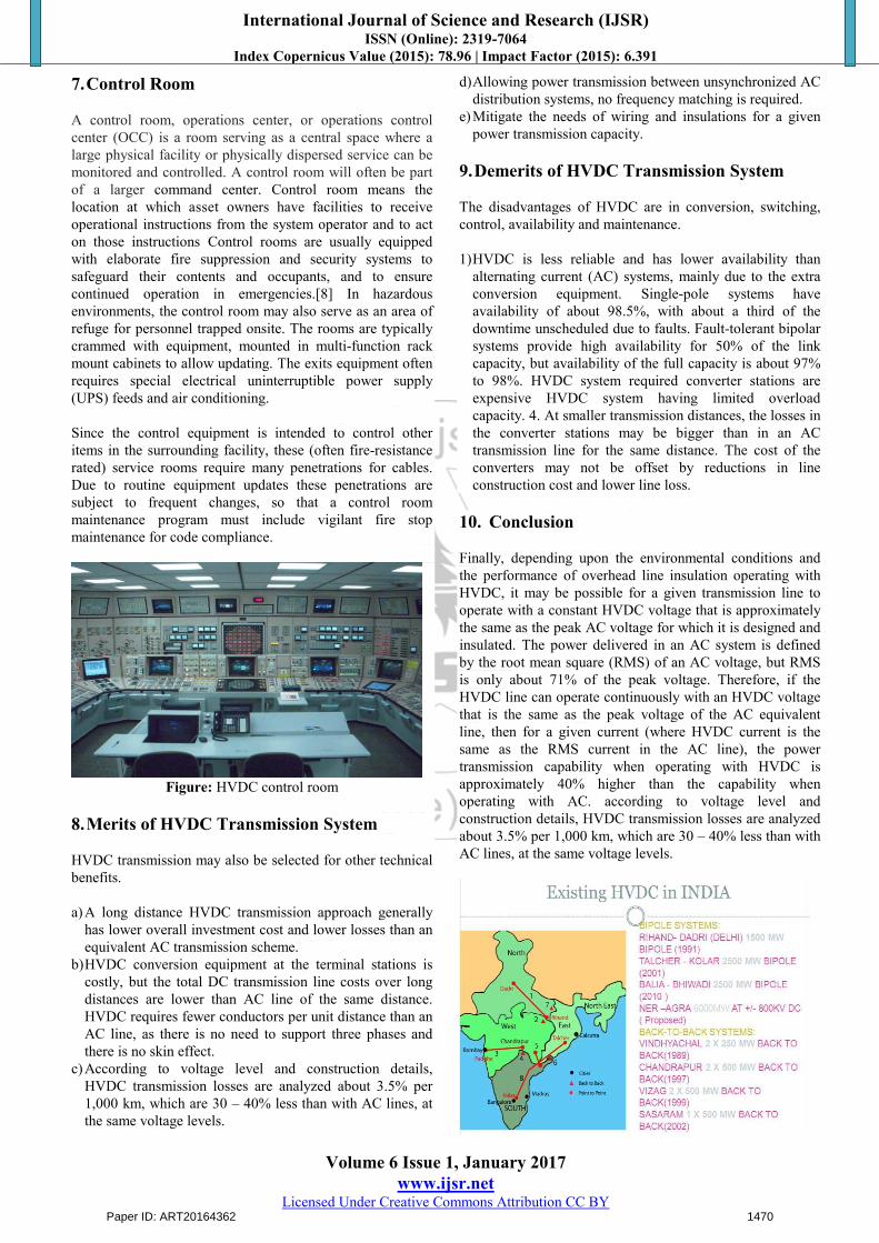
7.Control Room
A control room, operations center, or operations controlcenter (OCC) is a room serving as a central space where alarge physical facility or physically dispersed service can bemonitored and controlled. A control room will often be partof a larger command center. Control room means the location at which asset owners have facilities to receive operational instructions from the system operator and to act on those instructions Control rooms are usually equipped with elaborate fire suppression and security systems tosafeguard their contents and occupants, and to ensure continued operation in emergencies.[8] In hazardous environments, the control room may also serve as an area ofrefuge for personnel trapped onsite. The rooms are typically crammed with equipment, mounted in multi-function rack mount cabinets to allow updating. The exits equipment often requires special electrical uninterruptible power supply(UPS) feeds and air conditioning.
Since the control equipment is intended to control otheritems in the surrounding facility, these (often fire-resistance rated) service rooms require many penetrations for cables. Due to routine equipment updates these penetrations are subject to frequent changes, so that a control room maintenance program must include vigilant fire stopmaintenance for code compliance.
Figure: HVDC control room
8.Merits of HVDC Transmission System
HVDC transmission may also be selected for other technicalbenefits.
a)A long distance HVDC transmission approach generallyhas lower overall investment cost and lower losses than anequivalent AC transmission scheme.
b)HVDC conversion equipment at the terminal stations iscostly, but the total DC transmission line costs over longdistances are lower than AC line of the same distance.HVDC requires fewer conductors per unit distance than anAC line, as there is no need to support three phases andthere is no skin effect.
c)According to voltage level and construction details,HVDC transmission losses are analyzed about 3.5% per1,000 km, which are 30 – 40% less than with AC lines, atthe same voltage levels.
d)Allowing power transmission between unsynchronized AC
distribution systems, no frequency matching is required.
e)Mitigate the needs of wiring and insulations for a given
power transmission capacity.
9.Demerits of HVDC Transmission System
The disadvantages of HVDC are in conversion, switching,control, availability and maintenance.
1)HVDC is less reliable and has lower availability than alternating current (AC) systems, mainly due to the extra conversion equipment. Single-pole systems have availability of about 98.5%, with about a third of the downtime unscheduled due to faults. Fault-tolerant bipolar systems provide high availability for 50% of the link capacity, but availability of the full capacity is about 97%to 98%. HVDC system required converter stations are expensive HVDC system having limited overload capacity. 4. At smaller transmission distances, the losses inthe converter stations may be bigger than in an ACtransmission line for the same distance. The cost of the converters may not be offset by reductions in line construction cost and lower line loss.
10. Conclusion
Finally, depending upon the environmental conditions andthe performance of overhead line insulation operating withHVDC, it may be possible for a given transmission line tooperate with a constant HVDC voltage that is approximatelythe same as the peak AC voltage for which it is designed andinsulated. The power delivered in an AC system is definedby the root mean square (RMS) of an AC voltage, but RMS is only about 71% of the peak voltage. Therefore, if the HVDC line can operate continuously with an HVDC voltage that is the same as the peak voltage of the AC equivalent line, then for a given current (where HVDC current is the same as the RMS current in the AC line), the power transmission capability when operating with HVDC isapproximately 40% higher than the capability when operating with AC. according to voltage level and construction details, HVDC transmission losses are analyzed about 3.5% per 1,000 km, which are 30 – 40% less than with AC lines, at the same voltage levels.
Paper ID: ART20164362 1470
International Journal of Science and Research (IJSR) ISSN (Online): 2319-7064
Index Copernicus Value (2015): 78.96 | Impact Factor (2015): 6.391
Volume 6 Issue 1, January 2017 www.ijsr.net
Licensed Under Creative Commons Attribution CC BY
References
[1] Narain. G. Hingorani, “Understanding FACTS, Concepts and Technology Of flexible AC Transmission Systems”, by IEEE Press USA.
[2] Laboratory Manual for Transmission line and fuzzy Trainer Kit Of Electrical Engineering Department NIT Warangal.
[3] S.M. Sadeghzadeh M. Ehsan “ Improvement ofTransient Stability Limit in Power System Transmission Lines Using Fuzzy Control of FACTS Devices,IEEETransactions on Power System Vol.13 No.3,August 1998
[4] A.M. Kulkarni, “Design of power system stabilizer for single-machine system using robust periodic output feedback controller”, IEE Proceedings Part – C, Vol. 150, No. 2, pp. 211 – 216, March 2003. Technical Reports: Papers from Conference Proceedings unpublished):
[5] Jaun Dixon,Luis Moran, Jose Rodrfguz,Ricardo Domke “Reactive power compensation technology state- of- art- review”(invited paper) Electrical Engineering Dept Pontifica Universidad Catolica De CHILE.
[6] C.M.Franch, “HVDC circuit breaker” a review identifying the future reaserch need power delivery IEEE transaction on vol. 26, pp. 998:1007, 2011.
[7] User guide on the use of PSCAD Available: http://pscad.com/products/pscad/
[8] L. Tang and B.T. Ooi "Protection of VSC :multi: terminal HVDC against DC faults," in power electronics specialist conference 2002 pesc 02,20002 IEEE thirdannual 2002, pp. 719:724
[9] Y.H.L.J. arrillaga N.R. Watson flexible power transmission:, the HVDC option wiley 2007.
[10] G. F. Tang, “HVDC Transmission Technology Based Voltage Source Converter,” Beijing: China Electric Power Press, 2010, pp. 2-36.
[11] L. Gyugyi, “Principles and applications of static, thyristor-controlled Shunt compensators,” IEEE Trans. Power App. Syst., vol. PAS-97, pp.1935–1945,Sept./Oct. 1978.
[12]“Reactive power and control by thyristor circuits,” IEEETrans.Ind. Applicat., vol. IA-15, pp. 521–532,Sept./Oct. 1979.
[13] S. E. Haque, N. H. Malik, and W. Shepherd, “Operationof a fixed Capacitor-thyristor controlled reactor (FC-TCR) power factor compensator,” IEEE Trans. Power App. Syst., vol. PAS-104, pp. 1385–1390, June 1985.
[14] Czech, P., reichert, K., Schweickardt, H.E. and Holm, H.," Static VAR systems in power transmission Principles, Solutions, Applications, Experiences with a 450 MVA unit in a 735 kV system," CIGRE' 28th Session, Working Group No.32-05,1980.
[15] Gupta, J.B., “A course in power systems", S.K Katarina publications. Tenth edition, 2005.
[16] Gyugyi, L. and Otto, R.A.," Static shunt compensation for voltage flicker reduction and power factor correction," Proc. of the American Power Conf., Vol. 38, pp. 1271-1286, 1976.
Paper ID: ART20164362 1471