Embed Size (px)
Citation preview

Chalmers University of Technology
University of Gothenburg
Department of Computer Science and Engineering
Göteborg, Sweden, December 2012
Analysis of ISO26262 standard application in development of steer-by-wire systems Master of Science Thesis in the Program Computer Science: Algorithms, Languages and Logic
ALIAKSANDR MARCHANKA
The Author grants to Chalmers University of Technology the non-exclusive right to publish the Work electronically and in a non-commercial purpose make it accessible on the Internet. The Author warrants that he/she is the author to the Work, and warrants that the Work does not contain text, pictures or other material that violates copyright law. The Author shall, when transferring the rights of the Work to a third party (for example a publisher or a company), acknowledge the third party about this agreement. If the Author has signed a copyright agreement with a third party regarding the Work, the Author warrants hereby that he/she has obtained any necessary permission from this third party to let Chalmers University of Technology store the Work electronically and make it accessible on the Internet.
Analysis of ISO26262 standard application in development of steer-by-wire systems ALIAKSANDR MARCHANKA © ALIAKSANDR MARCHANKA, December 2012. Examiner: MARINAPAPATRIANTAFILOU Chalmers University of Technology Department of Computer Science and Engineering SE-412 96 Göteborg Sweden Telephone + 46 (0)31-772 1000 Department of Computer Science and Engineering Göteborg, Sweden. December 2012.
Master's thesis: Analysis of ISO26262 standard application in development of steer-by-wire systems i
Abstract Software for automotive industry has to be as reliable as it is reasonably possible avoid human and property hazard, caused by its failure. That is why industry is constantly producing software development standards, which capture the best practices, recommendations and state-of-the art development technologies. Hence companies are constantly challenged by the need to align their current development processes with the upcoming standards like ISO 26262 standard. This work aims to perform the comparative analysis of the processes applied in regard to the software development, as implemented in a specific project. Besides the analysis, as a result of this work, a tool to support Fault Tree Analysis has been developed. Fault Tree Analysis is recommended by the ISO26262 standard and a tool that implements it can significantly decrease the amount of effort required to produce safe and reliable software according to ISO26262. Keywords: ISO 26262, Fault tree analysis, Safety-critical software, Gap analysis.
Master's thesis: Analysis of ISO26262 standard application in development of steer-by-wire systems ii
Acknowledgment
This Master's thesis report has been written as the final part of the Master's program Computer Science: Algorithms, Languages and Logic at Chalmers University of Technology, Sweden. The subject was chosen in collaboration with CPAC Systems AB company at Göteborg, where the thesis also has been performed. I would like to thank my supervisors Marco Monzani and Lars Appelkvist at CPAC Systems AB for their guidance and support during this research work. I am grateful for their valuable supervision, motivating ideas and never-ending optimism. I would also like to thank my examiner Marina Papatriantafilou from Department of Computer Science and Engineering at Chalmers University of Technology for her valuable advices and support during the work. Furthermore, I would like to thank those people who helped and supported us time to time during the work whose names are not mentioned here. I would like to thank you all!
Master's thesis: Analysis of ISO26262 standard application in development of steer-by-wire systems iii
Table of Contents
ABSTRACT ............................................................................................................................................................... I
ACKNOWLEDGMENT .............................................................................................................................................. II
TABLE OF CONTENTS ............................................................................................................................................. III
LIST OF FIGURES ....................................................................................................................................................IV
LIST OF TABLES......................................................................................................................................................IV
ABBREVIATED TERMS ............................................................................................................................................V
1 INTRODUCTION ............................................................................................................................................. 1
1.1 BACKGROUND .................................................................................................................................................. 1 1.2 PROBLEM STATEMENT ........................................................................................................................................ 1 1.3 DESCRIPTION OF THE WORK ................................................................................................................................ 2 1.4 LIMITATIONS .................................................................................................................................................... 2
2 THEORETICAL BACKGROUND ......................................................................................................................... 3
2.1 AGILE DEVELOPMENT ......................................................................................................................................... 3 2.2 ISO 26262 STANDARD ...................................................................................................................................... 3 2.3 ECLIPSE MODELING FRAMEWORK ......................................................................................................................... 5 2.4 FAULT TREE ANALYSIS ......................................................................................................................................... 5
3 PURPOSE OF THE WORK ................................................................................................................................ 8
4 RESEARCH APPROACH ................................................................................................................................... 9
5 GAP ANALYSIS BETWEEN ISO 26262 STANDARD AND RFP PROJECT PROCESSES .......................................... 10
5.1 INITIATION OF SOFTWARE PRODUCT DEVELOPMENT ............................................................................................... 10 5.2 SPECIFICATION OF SOFTWARE SAFETY REQUIREMENTS ............................................................................................ 12 5.3 SOFTWARE ARCHITECTURAL DESIGN .................................................................................................................... 14 5.4 SOFTWARE UNIT DESIGN AND IMPLEMENTATION ................................................................................................... 19 5.5 SOFTWARE UNIT TESTING .................................................................................................................................. 21 5.6 SOFTWARE INTEGRATION AND TESTING................................................................................................................ 23 5.7 VERIFICATION OF SOFTWARE SAFETY REQUIREMENTS.............................................................................................. 24
6 DEVELOPMENT OF A TOOL FOR FAULT TREE ANALYSIS ............................................................................... 25
6.1 REQUIREMENT ANALYSIS .................................................................................................................................. 25 6.2 ECLIPSE METAMODEL ....................................................................................................................................... 25
6.2.1 Primary and Intermediate Events .......................................................................................................... 26 6.2.2 Gates ...................................................................................................................................................... 27 6.2.3 Transfer Nodes ....................................................................................................................................... 30
6.3 VALIDATION ................................................................................................................................................... 30 6.4 PROBABILITY COMPUTATION ............................................................................................................................. 31 6.5 STEPWISE PROBABILITY EVALUATION ................................................................................................................... 33
7 CONCLUSION ............................................................................................................................................... 35
8 FUTURE IMPROVEMENTS ............................................................................................................................ 36
9 REFERENCES ................................................................................................................................................ 37
10 APPENDIXES ................................................................................................................................................ 38
Master's thesis: Analysis of ISO26262 standard application in development of steer-by-wire systems iv
List of figures Figure 1: Overview of ISO 26262 .................................................................................................................. 4 Figure 2:A typical fault tree .......................................................................................................................... 6 Figure 3:V-model software development process .................................................................................... 10 Figure 4:Specification of software safety requirements ........................................................................... 12 Figure 5: RFP System level components .................................................................................................... 16 Figure 6: Safety monitor diagram .............................................................................................................. 17 Figure 7: Source code reviews and testing procedure .............................................................................. 19 Figure 8: Unit testing use case diagram ..................................................................................................... 21 Figure 9: Test methods ............................................................................................................................... 23 Figure 10: Quantitative analysis support ................................................................................................... 25 Figure 11: Events diagram .......................................................................................................................... 26 Figure 12: Adding child node to a gate ...................................................................................................... 27 Figure 13: Gates diagram ............................................................................................................................ 27 Figure 14: Dependence nodes diagram ..................................................................................................... 28 Figure 15: And gate constraint definition .................................................................................................. 29 Figure 16: Or gate constraint definition..................................................................................................... 29 Figure 17: Transfer nodes diagram ............................................................................................................ 30 Figure 18: Validation screenshot................................................................................................................ 31 Figure 19: Intersection of two events ........................................................................................................ 32 Figure 20:Union of two events ................................................................................................................... 32 Figure 21: Exclusive union of two events .................................................................................................. 32 Figure 22: Stepwise probability evaluation step 1 .................................................................................... 33 Figure 23: Stepwise probability evaluation step 2 .................................................................................... 33 Figure 24: Stepwise probability evaluation step 3 .................................................................................... 34
List of tables Table 1: Fault tree nodes .............................................................................................................................. 7 Table 2: Gimpel support of MISRAC rules checking .................................................................................. 10 Table 3: Topics to be covered by modeling and coding guidelines ........................................................... 11 Table 4: Notations for software architectural design ............................................................................... 14 Table 5: Principles for software architectural design ................................................................................ 15 Table 6: Mechanisms for error detection at the software architectural level ......................................... 15 Table 7: Mechanisms for error handling at the software architectural level........................................... 17 Table 8: Methods for the verification of the software architectural design ............................................ 18 Table 9: Methods for the verification of software unit design and implementation .............................. 20 Table 10: Methods for software unit testing ............................................................................................. 22 Table 11: Methods for deriving test cases for software unit testing ........................................................ 22 Table 12: Structural coverage metrics at the software unit level ............................................................. 22 Table 13: Structural coverage metrics at the software architectural level .............................................. 23 Table 14: Test environments for conducting the software safety requirements verification ................. 24
Master's thesis: Analysis of ISO26262 standard application in development of steer-by-wire systems v
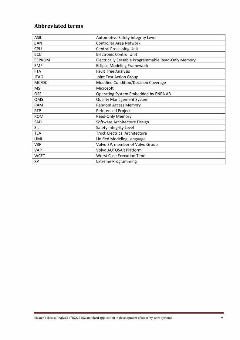
Abbreviated terms
ASIL Automotive Safety Integrity Level
CAN Controller Area Network
CPU Central Processing Unit
ECU Electronic Control Unit
EEPROM Electrically Erasable Programmable Read-Only Memory
EMF Eclipse Modeling Framework
FTA Fault Tree Analysis
JTAG Joint Test Action Group
MC/DC Modified Condition/Decision Coverage
MS Microsoft
OSE Operating System Embedded by ENEA AB
QMS Quality Management System
RAM Random Access Memory
RFP Referenced Project
ROM Read-Only Memory
SAD Software Architecture Design
SIL Safety Integrity Level
TEA Truck Electrical Architecture
UML Unified Modeling Language
V3P Volvo 3P, member of Volvo Group
VAP Volvo AUTOSAR Platform
WCET Worst Case Execution Time
XP Extreme Programming

Master's thesis: Analysis of ISO26262 standard application in development of steer-by-wire systems 1
1 Introduction
1.1 Background In order to produce safety-critical software, software development companies use special tools and development techniques suggested by appropriate standards. One of such standards is ISO 266262 which concerns mainly functional safety. The standard comprises of a set of rules and recommendations on how to achieve the required level of confidence of software quality. Safety-critical software must meet tight reliability constraints. From the functional point of view this means that software development company must perform various type of code analysis giving statistical guaranties that a particular function will behave as intended. Runtime self-diagnostic techniques need to be used to tolerate hardware faults. Rigorous notations need to be used to specify the intended behavior of software units. Due to the requirements implied by safety-critical software domain, software development process is built on the basis of different standards. These standards cover various aspects of systems development, having functional safety among the others. Standards on their own are continuously developed: new technologies, research results are introduced. For companies within safety-critical domain this means that they need to constantly adopt new development standards. This brings up a challenging question: how to adopt new standards while still maintaining the compliance with previously adopted standard? Half of the current work is dedicated to gap analysis between a number of adopted standards and the incoming one. The structure of the analysis is largely independent of the underlying standards and can be reused to perform similar type of research. Throughout the whole report the problem is analyzed from two perspectives: from the perspective of particular project and general development methodology adopted in the company. One way to avoid recurring low level errors is to automate some aspects of software development process. The second part of this work is dedicated to the development of fault tree analysis tool. The experience of the development of this tool can be used as a pattern on how to detect parts in a standard, that are suitable for automation.
1.2 Problem statement CPAC Systems AB, Göteborg, Sweden, is analyzing the possibility to develop a steer-by-wire system for the industrial vehicle industry. As of today, this would imply compliance with the ISO15998 safety standard. The ISO26262 is the incoming standard adopted by vehicle industry in general, and a version dedicated to the earth moving machines is on its way. In fact, ISO26262 is seen as “state of the art” when it comes to safety in all vehicle applications. ISO26262 is derived from the widespread IEC61508, the ground to all safety standards practically applied within all industrial segments (including avionics). CPAC has to provide evidence of capability when it comes to managing with the standard - a thing which can easily become an unbearable burden in terms of resource and time investments, because of the heavy requirements the standard poses on the development processes. The purpose of the job is identification of a reasonably effective procedure to achieve the compliance, without compromising the safety, in relation to steer-by-wire applications.

Master's thesis: Analysis of ISO26262 standard application in development of steer-by-wire systems 2
Work has been done at CPAC to get closer to this target, and this is a pre-requisite behind the thesis work, which has in itself very broad reach. The focus is anyway on the general procedures, system analysis and, as far as possible, principles for software design and development.
1.3 Description of the work This work mainly consists of two parts. The former is a comparative analysis between processes, currently implemented by CPAC within a specific project, and ISO 26262 standard. The company constantly adopts relevant standards and ISO 15998, Automotive SPICE, Agile and Autosar currently among them. Purpose of the work is to analyze the differences between the processes as of today and what is required to fulfill ISO26262. Development standards address the whole process of system development however this thesis addresses only the software development area. The reference project that was considered is herein after named with the acronym RFP. It is important to underline that the processes as implemented in the RFP do not necessarily represent the state of the art within CPAC or Volvo. In fact, the electronics and software developed within the RFP are not safety critical. The RFP was chosen in consequence of the availability and competence of the resources dedicated to it, which made the execution of this thesis work possible. The latter part of the work is dedicated to fault tree analysis (FTA). Fault tree analysis is a deductive failure analysis technique, used to determine the probability of a particular functional failure. This type of analysis is well-adopted in the industry and CPAC applies it to produce safety-critical systems. ISO 26262 references fault tree analysis and insists on its application. Considering this high demand for the technique, a tool to support fault tree analysis has been developed as part of this thesis work. FTA analysis tools is built as a plugin to the Eclipse platform, which is widespread across the industry. The tool is capable of building fault trees, enforcing their structural properties. The system architect can take advantage of a graphical editor with an easy to use interface and rich validation capabilities. The tool performs fault tree analysis on the fly, updating relevant properties as parts of the fault tree become valid. Results of the work are saved as projects and the tool allows to build component libraries for later reuse. An added value of the fault tree analysis tools is that its source code is under control of the company which makes it possible to enrich the tool with functionality, specific to a single one project. This is not possible with commercial tools as their source code is not disclosed meaning that they have limited flexibility. In general, when a new piece of theory is introduced, there is a time before an appropriate tool support emerges. This time can be reduced when using in-house made tools.
1.4 Limitations The main limitation of the tool being developed is its responsiveness. To remain usable interactive tools need to perform all their calculations in a reasonable amount of time. Careful design is required to divide functional features of the software into two groups: performance intensive and those that can be executed in linear time. Section 6.3 Validation describes the solution in details. Processes that require linear time to complete are run constantly as soon as the user makes any change. On the other hand more performance intensive operations are run on demand.

Master's thesis: Analysis of ISO26262 standard application in development of steer-by-wire systems 3
2 Theoretical Background
2.1 Agile development The Agile software development methodology is actually a group of software development methods, based on iterative methodologies. Agile Manifesto [12] declared the following priorities:
Individuals and interactions over processes and tools,
Working software over comprehensive documentation,
Customer collaboration over contract negotiation,
Responding to change over following a plan. The following 12 principles are the basis of the Agile Manifesto [12]:
1. Achieve customer satisfaction by rapid delivery of useful software 2. Welcome changing requirements, even late in development 3. Working software is delivered frequently 4. Working software is the principal measure of progress 5. Sustainable development, able to maintain a constant pace 6. Close, daily co-operation between business people and developers 7. Face-to-face conversation is the best form of communication 8. Projects are built around motivated individuals, who should be trusted 9. Continuous attention to technical excellence and good design 10. Simplicity - the art of maximizing the amount of work not done - is essential 11. Self-organizing teams 12. Regular adaptation to changing circumstances
One difference between agile methodology and traditional methods like waterfall model is that in agile testing is done during the development phase: engineers are encouraged to write test before they actually write the software. In traditional methods, testing is done after the development phase. Agile methods are often thought to be opposite to the disciplined methods (e.g. waterfall or cleanroom). However, agile methodology can be used in development safety-critical software as well, since it mostly addresses planning and is not anyhow preventing rigorous or formal methods to be used at the same time.
2.2 ISO 26262 standard ISO 26262 is the adaptation of IEC 61508 standard to comply with demands specific to the application domain of electrical and electronic systems in road vehicles. Safety is one of the key features of the future automobile development. New functionalities in areas such as driver assistance, propulsion, in vehicle dynamics control and safety systems touch the domain of system safety engineering. Development of these functionalities will increase the demand for safe system development processes and the need to provide evidence that all reasonable system safety objectives are satisfied. With the trend of increasing technological complexity, software content and mechatronic implementation, there are increasing risks from systematic failures and random hardware failures. ISO 26262 includes guidance to avoid these risks by providing appropriate requirements and processes. In order to achieve system safety a number of safety measures need to be applied. They are implemented on a variety of technologies and applied at the various levels of the development process.

Master's thesis: Analysis of ISO26262 standard application in development of steer-by-wire systems 4
Although ISO 26262 is targeted at functional safety, it provides a framework within which safety-related systems based on other technologies can be considered. The following figure shows the overall structure of the ISO 26262 standard, which is based on a V-model as a reference process model for the different phases of product development.
Figure 1: Overview of ISO 26262

Master's thesis: Analysis of ISO26262 standard application in development of steer-by-wire systems 5
The V-Model demonstrates the relationships between each phase of the development life cycle and its associated phase of testing. The horizontal and vertical axes represents time or project completeness (left-to-right) and level of abstraction, respectively. One of the core ideas of ISO 26262 standard is automotive safety integrity level (ASIL). It is one of four levels, used to specify the item's necessary requirements of ISO 26262 and safety measures to apply for avoiding an unreasonable residual risk. Levels range from A to D with D representing the most stringent and A the least stringent level.
2.3 Eclipse modeling framework Eclipse is a software development environment that consists of the integrated development environment and a set of extensions, called plug-ins. In general, Eclipse has plug-ins that support development of programs in Java, C++ and other languages. However the platform itself is not bound in any way to these capabilities. It is possible to write a general purpose application with rich graphical user interface, based on Eclipse platform. Here Eclipse modeling framework (EMF) comes in. EMF implies model driven approach to plug-in development. It is capable of generating code for EMF models, called "ecore". EMF-based modeling is the foundation for data sharing among tools and applications in Eclipse. One can see EMF models as an extension of entity-relationship modeling. More specifically, relations are classified as parent-child relations, references; multiplicity constraints can be introduced. Eclipse provides a standard way to implement wide adopted range of features, common to applications with rich graphical interface. XML serialization, validation, model-view separation are among them.
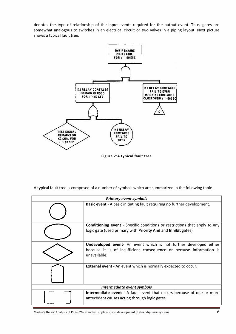
2.4 Fault tree analysis Fault tree analysis can be described as an analytical technique, where an undesired state of the system is specified (usually a state that is critical from a safety perspective) and the system is analyzed in the context of its environment and operation to find all the ways in which the undesired event can occur. The fault tree itself is a graphical model of the various parallel and sequential combinations of faults that will result in the occurrence of the predefined undesired event. The faults can be events that are associated with component hardware failures, human errors, or any other events which can lead to the undesired event. A fault tree thus depicts the logical interrelations of basic events that lead to the undesired event - which is the top event of the fault tree. A fault tree is not intended to be a model of all possible system failures or all possible causes for system failure. It is rather built starting from its top event, which is some particular system failure mode that is of particular concern. The tree thus contains only those faults that contribute to this top event. Moreover, the collection of these faults is not exhaustive: only the most credible faults, as they are defined by system engineer, are considered. One point that should be mentioned is that a fault tree is not in itself a quantitative model. This type of analysis is just one possible option. Cut set analysis is for instance another option. In general ISO 26262 standard does not imply use of any particular type of analysis, based on fault trees. It is up to system engineer to decided which is more appropriate in a given case. A fault tree comprises entities called gates which serve the purpose to permit or inhibit the passage of fault logic through the tree. The gates show the relationships of causal events needed for the occurrence of another event. This event is the "output" of the gate, and is therefore placed in the tree on a higher level than its causal events; the causal events are the "inputs" to the gate. The gate symbol
Master's thesis: Analysis of ISO26262 standard application in development of steer-by-wire systems 6
denotes the type of relationship of the input events required for the output event. Thus, gates are somewhat analogous to switches in an electrical circuit or two valves in a piping layout. Next picture shows a typical fault tree.
Figure 2:A typical fault tree
A typical fault tree is composed of a number of symbols which are summarized in the following table.
Primary event symbols
Basic event - A basic initiating fault requiring no further development.
Conditioning event - Specific conditions or restrictions that apply to any logic gate (used primary with Priority And and Inhibit gates).
Undeveloped event- An event which is not further developed either because it is of insufficient consequence or because information is unavailable.
External event - An event which is normally expected to occur.
Intermediate event symbols
Intermediate event - A fault event that occurs because of one or more antecedent causes acting through logic gates.

Master's thesis: Analysis of ISO26262 standard application in development of steer-by-wire systems 7
Gate symbols
And - Output fault occurs if all of the input faults occur.
Or - Output fault occurs if at least one of the input faults occurs.
Exclusive Or - Output fault occurs if exactly one of the input faults occurs.
Priority And - Output fault occurs if all of the input faults occur in a specific sequence (the sequence is represented by a Conditioning event drawn to the right of the gate).
Inhibit - Output fault occurs if the (single) input fault occurs in the presence of an enabling condition (the enabling condition is represented by a Conditioning event drawn to the right of the gate)
Transfer symbols
Transfer In - Indicates that the tree is developed further at the occurrence of the corresponding Transfer Out (e.g. on another page).
Transfer Out - Indicates that this portion of the tree must be attached at the corresponding Transfer In.
Table 1: Fault tree nodes
Master's thesis: Analysis of ISO26262 standard application in development of steer-by-wire systems 8
3 Purpose of the work One of the challenges with software development for automotive industry is that it has to be qualified as safety critical to reduce the risk of possible hazard, resulting from its failure. The exact meaning of “safety critical” is determined by the legal context – when it comes to automotive applications, as described before, the ISO26262 represents this context. The safety standards are reviewed, ISO26262 adapted to different vehicle segments, and harmonization is required. This is an ongoing process and companies like CPAC Systems AB have to keep their development processes up to date. Currently CPAC’s software development processes are based on the agile methodology. By default, the ISO 26262 standard implies waterfall processes. One of the challenges for the company is implementing the standard and still safeguard the advantages of agile methods – the flexibility before all. This work is intended to be the basis for the documentation, required to go through certification process, and is therefore quite relevant to the company. After the process analysis described above, a tool to support fault tree analysis is developed. This type of failure analysis is used by CPAC and is actually widespread across different industry segments. The purpose of a dedicated tool is reducing the amount of time required by system engineers to perform the analysis itself. The FTA tool enforces constraints implied by fault tree analysis and performs quantitative computations. This increases the reliability of the analysis and therefore of the product.
Master's thesis: Analysis of ISO26262 standard application in development of steer-by-wire systems 9
4 Research Approach The gap analysis has been executed by carrying out two types of activity:
Documents review. A number of internal documents have been reviewed including project plans, system and software architecture designs, reports etc.
Employee interviews. In order to perform the in-depth analysis and understand how the processes are followed up, the employees were interviewed.
The company documents contain precise description of the procedures, best practices and recommendations that the development methodology consists of. Also the ISO 26262 standard is a set of requirements and recommendations. To perform the gap analysis one needs to map ISO 26262 requirements onto the development process as they are implemented as of today. Original documents are extensively referenced to add value to this research: CPAC should be able to use this report during certification procedure. The working process at CPAC is described in a range of internal documents. The idea of gap analysis was to map ISO standard recommendations onto the company's processes. On the other hand, the importance of the interviews must be underlined, as they and give a way to collect the required data and to assign correct priorities to different pieces of information. Interview is a widely used method for collecting qualitative research data because “it is perceived as ‘talking’ and
talking is natural” Dale Griffee [14]. The conclusions, drawn after the gap analysis were verified by interviews. According to Mack et all [13] there are three main methods of qualitative research. These are:
Participant observation—where the researcher also occupies a role or part in the setting, in addition to observing.
In depth interviews— face to face conversation, to explore the issues or topics in detail. Any preset questions are not used, yet the discussions shaped by a defined set of topics.
Focus group— a method of group interview, group interaction is explicitly included and used to generate data.
In this work the two last methods were used. The first method - participant observation - was not used because of its time consuming nature.

Master's thesis: Analysis of ISO26262 standard application in development of steer-by-wire systems 10
5 Gap Analysis between ISO 26262 standard and RFP project processes
5.1 Initiation of software product development The software development process at CPAC is built around agile processes and iterative model, yet it maps directly onto the V-model, which is referred to by ISO 26262 standard. More specifically, the work is divided into increments called “sprints”. Each sprint loops through a number of development and related testing activities.
Figure 3:V-model software development process
CPAC applies a number of languages and software tools during software development. Most of what follows is applicable to the RFP project only, one of a number carried out at CPAC at the time this work was done. The main implementation language is C. The language being used conforms to ISO/IEC 14882:1998 standard, which unambiguously defines it's syntax and semantics. For the actual development a subset of original C language is used. This subset is based on MISRA C coding guidelines and defined in the a CPAC internal document. Compliance with MISRA C 2004 standard is checked using PC-Lint tool which generates rule violation reports. According to the document, provided by Gimpel Software http://gimpel.com/html/misra2.pdf, the tool is capable of checking of the large majority of the MISRA rules, as summarized in the following table:
Checked Partially Checked
Not Statically Checkable
Not Yet Checked
Totals
Required Rules 115 1 5 1 122
Advisory Rules 17 1 2 0 20
Totals 132 2 7 1 142 Table 2: Gimpel support of MISRAC rules checking
Most of the rules can be checked automatically and the tool is capable of analyzing code against them. However, some rules can be checked only by a developer review. For the detailed description of which rules are covered see the referenced document.
Master's thesis: Analysis of ISO26262 standard application in development of steer-by-wire systems 11
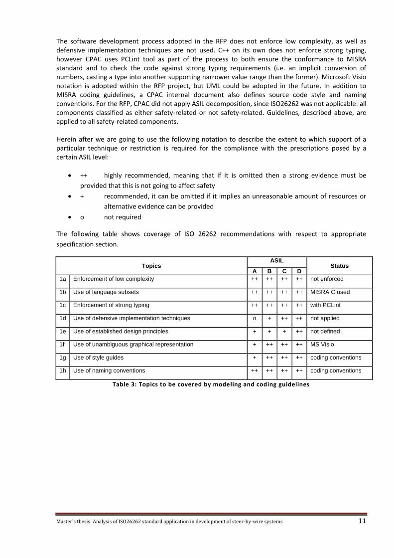
The software development process adopted in the RFP does not enforce low complexity, as well as defensive implementation techniques are not used. C++ on its own does not enforce strong typing, however CPAC uses PCLint tool as part of the process to both ensure the conformance to MISRA standard and to check the code against strong typing requirements (i.e. an implicit conversion of numbers, casting a type into another supporting narrower value range than the former). Microsoft Visio notation is adopted within the RFP project, but UML could be adopted in the future. In addition to MISRA coding guidelines, a CPAC internal document also defines source code style and naming conventions. For the RFP, CPAC did not apply ASIL decomposition, since ISO26262 was not applicable: all components classified as either safety-related or not safety-related. Guidelines, described above, are applied to all safety-related components. Herein after we are going to use the following notation to describe the extent to which support of a particular technique or restriction is required for the compliance with the prescriptions posed by a certain ASIL level:
++ highly recommended, meaning that if it is omitted then a strong evidence must be
provided that this is not going to affect safety
+ recommended, it can be omitted if it implies an unreasonable amount of resources or
alternative evidence can be provided
o not required
The following table shows coverage of ISO 26262 recommendations with respect to appropriate
specification section.
Topics ASIL
Status A B C D
1a Enforcement of low complexity ++ ++ ++ ++ not enforced
1b Use of language subsets ++ ++ ++ ++ MISRA C used
1c Enforcement of strong typing ++ ++ ++ ++ with PCLint
1d Use of defensive implementation techniques o + ++ ++ not applied
1e Use of established design principles + + + ++ not defined
1f Use of unambiguous graphical representation + ++ ++ ++ MS Visio
1g Use of style guides + ++ ++ ++ coding conventions
1h Use of naming conventions ++ ++ ++ ++ coding conventions
Table 3: Topics to be covered by modeling and coding guidelines
Master's thesis: Analysis of ISO26262 standard application in development of steer-by-wire systems 12
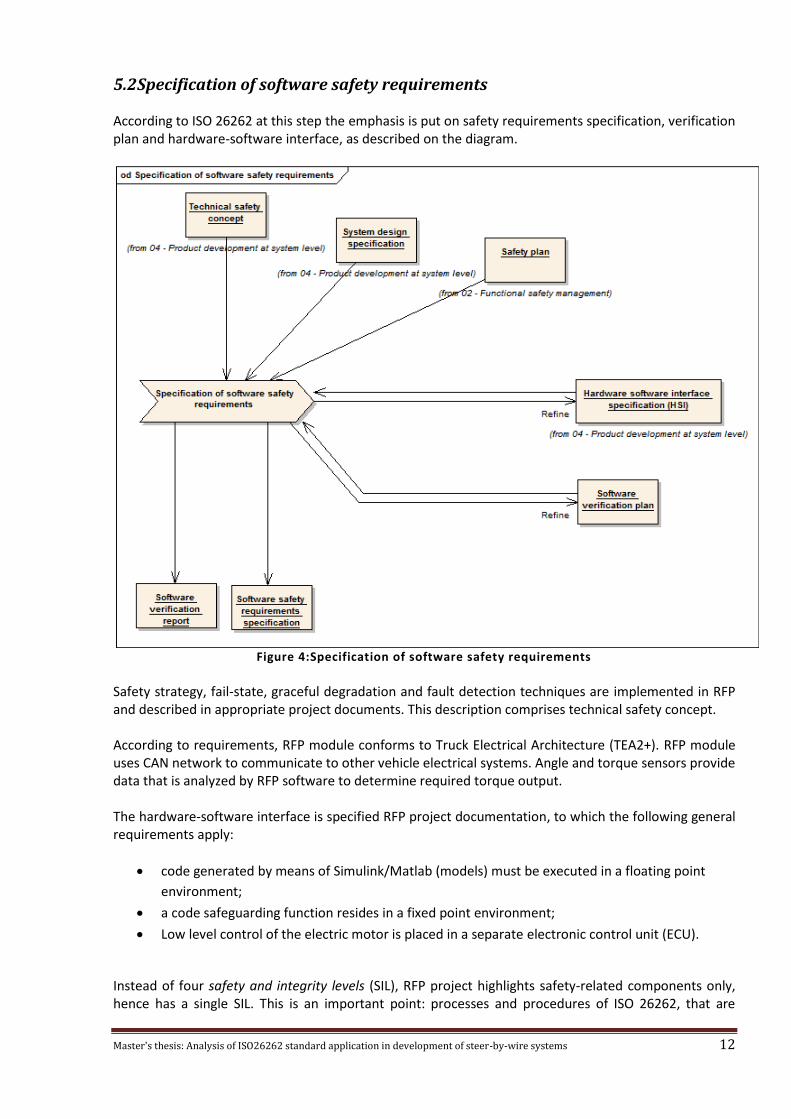
5.2 Specification of software safety requirements According to ISO 26262 at this step the emphasis is put on safety requirements specification, verification plan and hardware-software interface, as described on the diagram.
Figure 4:Specification of software safety requirements
Safety strategy, fail-state, graceful degradation and fault detection techniques are implemented in RFP and described in appropriate project documents. This description comprises technical safety concept. According to requirements, RFP module conforms to Truck Electrical Architecture (TEA2+). RFP module uses CAN network to communicate to other vehicle electrical systems. Angle and torque sensors provide data that is analyzed by RFP software to determine required torque output. The hardware-software interface is specified RFP project documentation, to which the following general requirements apply:
code generated by means of Simulink/Matlab (models) must be executed in a floating point
environment;
a code safeguarding function resides in a fixed point environment;
Low level control of the electric motor is placed in a separate electronic control unit (ECU).
Instead of four safety and integrity levels (SIL), RFP project highlights safety-related components only, hence has a single SIL. This is an important point: processes and procedures of ISO 26262, that are
Master's thesis: Analysis of ISO26262 standard application in development of steer-by-wire systems 13
intended to ensure functional safety of embedded systems, changes significantly depending on the ASIL. Treating all safety-related components as if they belonged to the highest ASIL D may result in development process that requires an unmotivated amount of effort and resources. The assigned ASIL level is derived from three aspects: controllability, probability of exposure and severity. For instance the part developed during RFP project has fail-safe state and in case of failure, driver is left with just power steering. This means that the controllability of the vehicle is affected insignificantly. As a consequence of that we will have level C1 assigned to the component and the component will at max get ASIL B level. The procedure is described in ISO 26262 part 7 section 7.4.4. ASIL decomposition as part of specification of software safety requirements is implied by section 6.4.3 of ISO 26262 part 6.
Master's thesis: Analysis of ISO26262 standard application in development of steer-by-wire systems 14
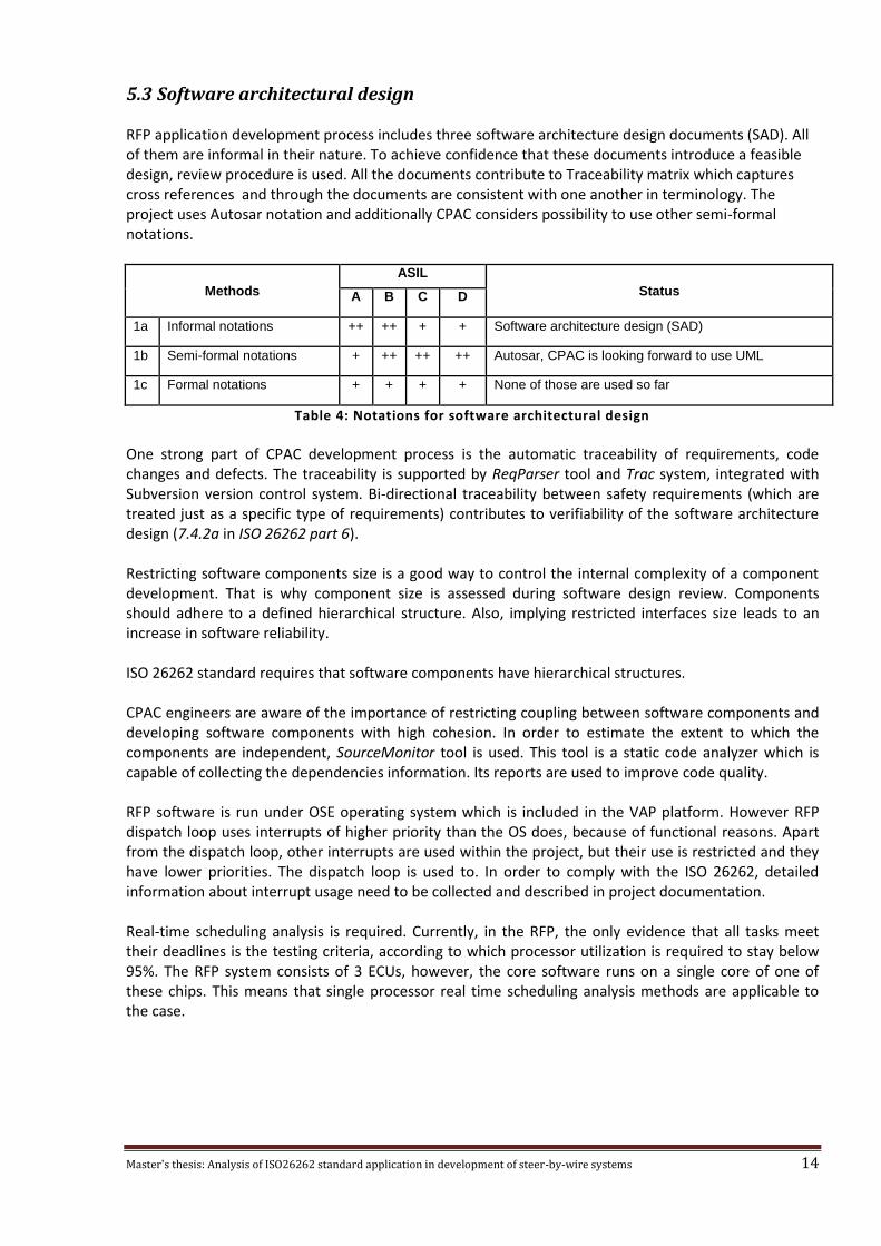
5.3 Software architectural design RFP application development process includes three software architecture design documents (SAD). All of them are informal in their nature. To achieve confidence that these documents introduce a feasible design, review procedure is used. All the documents contribute to Traceability matrix which captures cross references and through the documents are consistent with one another in terminology. The project uses Autosar notation and additionally CPAC considers possibility to use other semi-formal notations.
Methods
ASIL
Status A B C D
1a Informal notations ++ ++ + + Software architecture design (SAD)
1b Semi-formal notations + ++ ++ ++ Autosar, CPAC is looking forward to use UML
1c Formal notations + + + + None of those are used so far
Table 4: Notations for software architectural design
One strong part of CPAC development process is the automatic traceability of requirements, code changes and defects. The traceability is supported by ReqParser tool and Trac system, integrated with Subversion version control system. Bi-directional traceability between safety requirements (which are treated just as a specific type of requirements) contributes to verifiability of the software architecture design (7.4.2a in ISO 26262 part 6). Restricting software components size is a good way to control the internal complexity of a component development. That is why component size is assessed during software design review. Components should adhere to a defined hierarchical structure. Also, implying restricted interfaces size leads to an increase in software reliability. ISO 26262 standard requires that software components have hierarchical structures. CPAC engineers are aware of the importance of restricting coupling between software components and developing software components with high cohesion. In order to estimate the extent to which the components are independent, SourceMonitor tool is used. This tool is a static code analyzer which is capable of collecting the dependencies information. Its reports are used to improve code quality. RFP software is run under OSE operating system which is included in the VAP platform. However RFP dispatch loop uses interrupts of higher priority than the OS does, because of functional reasons. Apart from the dispatch loop, other interrupts are used within the project, but their use is restricted and they have lower priorities. The dispatch loop is used to. In order to comply with the ISO 26262, detailed information about interrupt usage need to be collected and described in project documentation. Real-time scheduling analysis is required. Currently, in the RFP, the only evidence that all tasks meet their deadlines is the testing criteria, according to which processor utilization is required to stay below 95%. The RFP system consists of 3 ECUs, however, the core software runs on a single core of one of these chips. This means that single processor real time scheduling analysis methods are applicable to the case.
Master's thesis: Analysis of ISO26262 standard application in development of steer-by-wire systems 15
Methods
ASIL
Status A B C D
1a Hierarchical structure of software components ++ ++ ++ ++ Need to be introduced
1b Restricted size of software components ++ ++ ++ ++ Taken into consideration
1c Restricted size of interfaces + + + + No restrictions are implied
1d High cohesion within each software component + ++ ++ ++ Taken into consideration
1e Restricted coupling between software components + ++ ++ ++ Analyzed with SourceMonitor
1f Appropriate scheduling properties ++ ++ ++ ++ Needs improvement
1g Restricted use of interrupts + + + ++ Procedure needs improvement
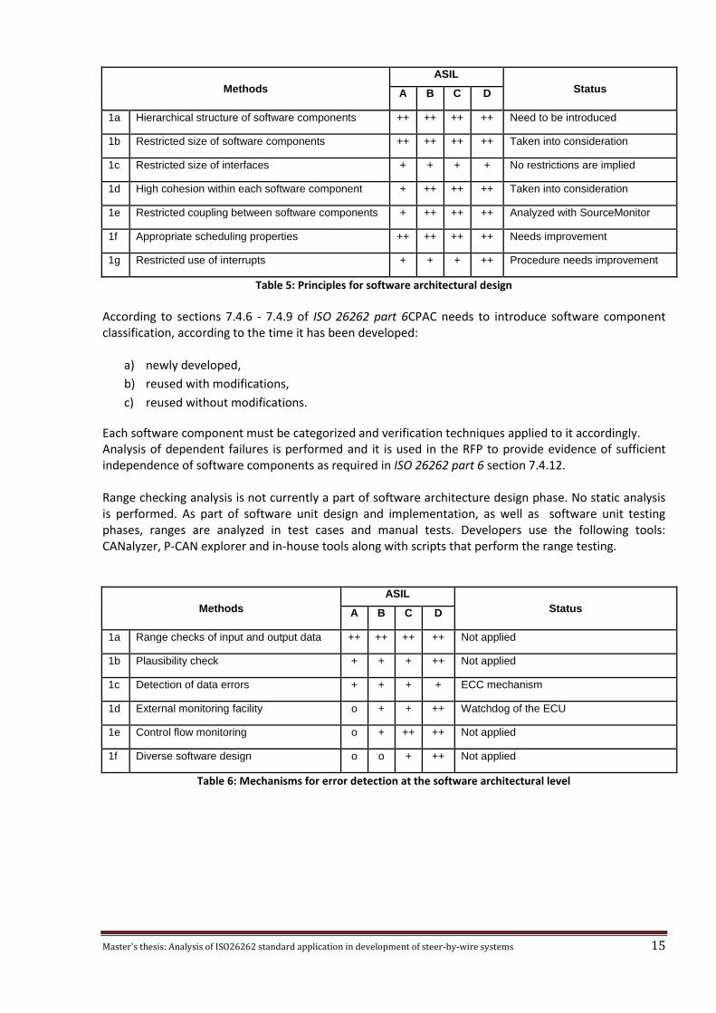
Table 5: Principles for software architectural design According to sections 7.4.6 - 7.4.9 of ISO 26262 part 6CPAC needs to introduce software component classification, according to the time it has been developed:
a) newly developed,
b) reused with modifications,
c) reused without modifications.
Each software component must be categorized and verification techniques applied to it accordingly. Analysis of dependent failures is performed and it is used in the RFP to provide evidence of sufficient independence of software components as required in ISO 26262 part 6 section 7.4.12. Range checking analysis is not currently a part of software architecture design phase. No static analysis is performed. As part of software unit design and implementation, as well as software unit testing phases, ranges are analyzed in test cases and manual tests. Developers use the following tools: CANalyzer, P-CAN explorer and in-house tools along with scripts that perform the range testing.
Methods
ASIL
Status A B C D
1a Range checks of input and output data ++ ++ ++ ++ Not applied
1b Plausibility check + + + ++ Not applied
1c Detection of data errors + + + + ECC mechanism
1d External monitoring facility o + + ++ Watchdog of the ECU
1e Control flow monitoring o + ++ ++ Not applied
1f Diverse software design o o + ++ Not applied
Table 6: Mechanisms for error detection at the software architectural level

Master's thesis: Analysis of ISO26262 standard application in development of steer-by-wire systems 16
Following diagram depicts the structure of RFP system level components.
Figure 5: RFP System level components
System consists of three electronic control units (ECU): NC, MP and DSP. NC ECU has two cores that run the software that controls torque force, produced by this unit and safety monitor. Safety monitor is responsible for detecting a hazardous condition and switching the motor off in case if such condition has been detected. This conforms with safety degradation concept: whenever RFP unit is about to produce torque force, which is considered hazardous, the force is not actually produced, unit still remains operational and the controllability of vehicle is not affected, since the driver is left with just hydraulic power steering. Two cores read data from CAN simultaneously. Safety monitor facility is used to support graceful degradation of the unit as well as to support fail-safe state. The actual logic of the monitor is derived from Simulink models, provided by V3P. These models are compiled by TargetLink into C code first and then compiled by WindRiver compiler into object code.

Master's thesis: Analysis of ISO26262 standard application in development of steer-by-wire systems 17
Figure 6: Safety monitor diagram
ECU is equipped with watchdog facility that provides static recovery mechanism. Described software safety mechanisms provide evidence towards conformance with section 7.4.13 of ISO 26262 part 6 and are summarized in the following table.
Methods
ASIL
Status A B C D
1a Static recovery mechanism + + + + Watchdog mechanism
1b Graceful degradation + + ++ ++ Safety monitor mechanism
1c Independent parallel redundancy o o + ++ Not applied
1d Correcting codes for data + + + + ECC mechanism
Table 7: Mechanisms for error handling at the software architectural level As part of the software architecture design phase, the following embedded software metrics are estimated:
a) execution time,
b) storage space (both RAM and ROM),
c) communication resources (CAN bus capabilities).
According to section 7.4.18 of ISO 26262 part 6 software design should be verified. CPAC engineers carry out informal reviews of the software design as well as formal reviews. However, verifications procedures need to be improved. Control flow and data flow analysis are the first candidates for improvement. ASIL D level also suggests that prototypes should be used and simulation of the dynamic parts of the design performed.

Master's thesis: Analysis of ISO26262 standard application in development of steer-by-wire systems 18
Methods
ASIL
Status A B C D
1a Walk-through of the design ++ + o o Informal review
1b Inspection of the design + ++ ++ ++ Formal review
1c Simulation of dynamic parts of the design + + + ++ Not performed
1d Prototype generation o o + ++ Not performed
1e Formal verification o o + + Not applied
1f Control flow analysis + + ++ ++ Not performed
1g Data flow analysis + + ++ ++ Not performed
Table 8: Methods for the verification of the software architectural design
Master's thesis: Analysis of ISO26262 standard application in development of steer-by-wire systems 19
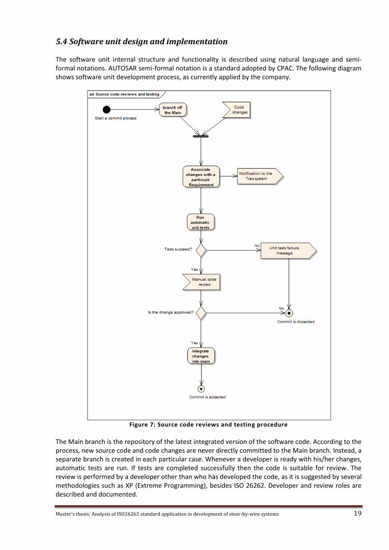
5.4 Software unit design and implementation The software unit internal structure and functionality is described using natural language and semi-formal notations. AUTOSAR semi-formal notation is a standard adopted by CPAC. The following diagram shows software unit development process, as currently applied by the company.
Figure 7: Source code reviews and testing procedure
The Main branch is the repository of the latest integrated version of the software code. According to the process, new source code and code changes are never directly committed to the Main branch. Instead, a separate branch is created in each particular case. Whenever a developer is ready with his/her changes, automatic tests are run. If tests are completed successfully then the code is suitable for review. The review is performed by a developer other than who has developed the code, as it is suggested by several methodologies such as XP (Extreme Programming), besides ISO 26262. Developer and review roles are described and documented.

Master's thesis: Analysis of ISO26262 standard application in development of steer-by-wire systems 20
The software review process is also defined and documented. According to it, the code is checked against its design specification and coding guidelines. Code coverage is estimated using Trace32 tool (statement coverage). Lauterbach Trace32 is a device connected to the CPU by means of JTAG plug. Trace32 among other features is capable of performing code coverage analysis. PowerTrace module is responsible for this analysis. However, the process does not directly enforce compliance with hardware-software interface. CPAC uses Trac system to establish the relation between a single code change and the requirement according to which this change has been made. This implies traceability of changes, required by 8.4.5 of ISO 26262 part 6. The following table lists the methods for static code validation, as defined by ISO standard and shows which ones are applied at CPAC.
Methods
ASIL
Status A B C D
1a Walk-through ++ + o o Supported by the review process
1b Inspection + ++ ++ ++ Supported by the review process
1b Semi-formal verification + + ++ ++ Not applied
1c Formal verification o o + + Not applied
1d Control flow analysis + + ++ ++ Not applied
1e Data flow analysis + + ++ ++ Not applied
1f Static code analysis + ++ ++ ++ Trace32 and PCLint are used
1g Semantic code analysis + + + + Not applied
Table 9: Methods for the verification of software unit design and implementation

Master's thesis: Analysis of ISO26262 standard application in development of steer-by-wire systems 21
5.5 Software unit testing Software development process defines overall software test strategy, according to which tests are classified into 6 categories. CPAC uses a custom tool called ReqParser to bind actual tests and their description in project documents to the requirements the tests are executed against. The result, produced by ReqParser, is stored in Traceability Matrix document. The established link exists for tests whenever the test is done against a specific requirement. Another type of tests - unit tests are applied to verify interfaces consistence. Loose coupling, enforced by design, allows to introduce unit tests and achieve close to 100% code coverage. At the same time this results in interface testing of software components, since stubs are used to isolate the component under testing (see the diagram). Currently CPAC does not apply any fault injection testing technique. Interface testing is not focused on what the components are during but rather on how they communicate. The emphasis is put on component relationship, including:
what components can expect from one another in terms of services,
how these services will be asked for,
how they will be given,
how to handle non-standard conditions, i.e. errors.
Unit testing on its own addresses those issues by isolating a component from the other components. Separate tests capture the contract the component has to obey to and high code coverage ratio means that all exceptional conditions are addressed as well as normal control flow.
Figure 8: Unit testing use case diagram
Each release worse case execution time (WCET) analysis is performed along with other resource usage analysis types. This is documented. More specifically, the following resource usage types are analyzed:
Average CPU load
EEPROM memory usage
FLASH memory usage both internal and external
RAM memory usage
Back-to-back comparison test between model and code is done for the model obtained from Volvo 3P. The following table gives a summary of methods for unit testing.
Master's thesis: Analysis of ISO26262 standard application in development of steer-by-wire systems 22
Methods ASIL
Status A B C D
1a Requirements-based test ++ ++ ++ ++ Main test type, tracked with ReqParser
1b Interface test ++ ++ ++ ++ Implicitly carried out by unit testing
1c Fault injection test + + + ++ Not applied
1d Resource usage test + + + ++ Performed at each release
1e Back-to-back comparison test between model and code, if applicable
+ + ++ ++ Obtained from Volvo 3P
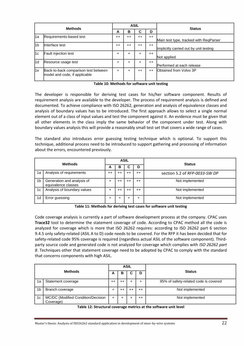
Table 10: Methods for software unit testing The developer is responsible for deriving test cases for his/her software component. Results of requirement analysis are available to the developer. The process of requirement analysis is defined and documented. To achieve compliance with ISO 26262, generation and analysis of equivalence classes and analysis of boundary values has to be introduced. The first approach allows to select a single normal element out of a class of input values and test the component against it. An evidence must be given that all other elements in the class imply the same behavior of the component under test. Along with boundary values analysis this will provide a reasonably small test set that covers a wide range of cases. The standard also introduces error guessing testing technique which is optional. To support this technique, additional process need to be introduced to support gathering and processing of information about the errors, encountered previously.
Methods ASIL
Status A B C D
1a Analysis of requirements ++ ++ ++ ++ section 5.2 of RFP-0033-SW DP
1b Generation and analysis of equivalence classes
+ ++ ++ ++ Not implemented
1c Analysis of boundary values + ++ ++ ++ Not implemented
1d Error guessing + + + + Not implemented
Table 11: Methods for deriving test cases for software unit testing Code coverage analysis is currently a part of software development process at the company. CPAC uses Trace32 tool to determine the statement coverage of code. According to CPAC method all the code is analyzed for coverage which is more that ISO 26262 requires: according to ISO 26262 part 6 section 9.4.5 only safety-related (ASIL A to D) code needs to be covered. For the RFP it has been decided that for safety-related code 95% coverage is required (regardless actual ASIL of the software component). Third-party source code and generated code is not analyzed for coverage which complies with ISO 26262 part 8. Techniques other that statement coverage need to be adopted by CPAC to comply with the standard that concerns components with high ASIL.
Methods
ASIL
Status A B C D
1a Statement coverage ++ ++ + + 95% of safety-related code is covered
1b Branch coverage + ++ ++ ++ Not implemented
1c MC/DC (Modified Condition/Decision Coverage)
+ + + ++ Not implemented
Table 12: Structural coverage metrics at the software unit level
Master's thesis: Analysis of ISO26262 standard application in development of steer-by-wire systems 23
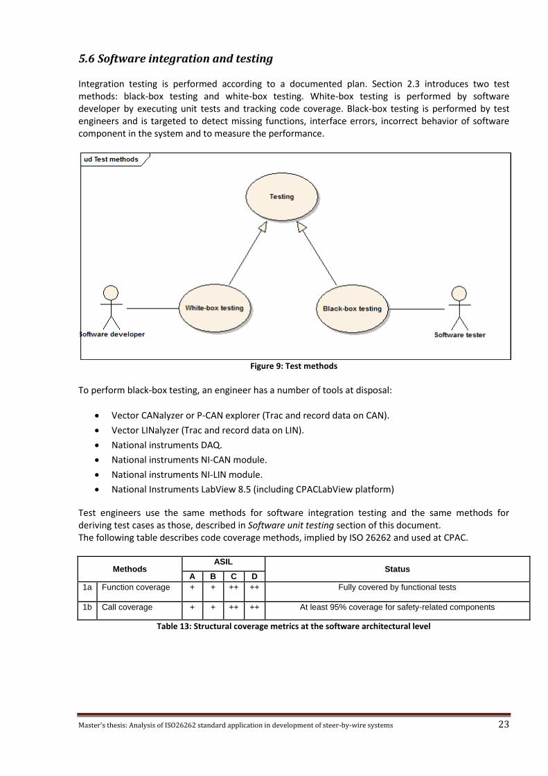
5.6 Software integration and testing Integration testing is performed according to a documented plan. Section 2.3 introduces two test methods: black-box testing and white-box testing. White-box testing is performed by software developer by executing unit tests and tracking code coverage. Black-box testing is performed by test engineers and is targeted to detect missing functions, interface errors, incorrect behavior of software component in the system and to measure the performance.
Figure 9: Test methods
To perform black-box testing, an engineer has a number of tools at disposal:
Vector CANalyzer or P-CAN explorer (Trac and record data on CAN).
Vector LINalyzer (Trac and record data on LIN).
National instruments DAQ.
National instruments NI-CAN module.
National instruments NI-LIN module.
National Instruments LabView 8.5 (including CPACLabView platform)
Test engineers use the same methods for software integration testing and the same methods for deriving test cases as those, described in Software unit testing section of this document. The following table describes code coverage methods, implied by ISO 26262 and used at CPAC.
Methods ASIL
Status A B C D
1a Function coverage + + ++ ++ Fully covered by functional tests
1b Call coverage + + ++ ++ At least 95% coverage for safety-related components
Table 13: Structural coverage metrics at the software architectural level

Master's thesis: Analysis of ISO26262 standard application in development of steer-by-wire systems 24
5.7 Verification of software safety requirements Verification process is planned and this plan documented. The process is documented and summarized in Traceability Matrix by ReqParser. Information about different types of tests is kept in Trac system. Test classification consists of the following classes of tests:
Unit Test
A Unit Test should be used to test design requirements and could also be used to test a functional requirement. A Unit Test should be implemented and executed together with the new feature. Specific important functions should always be unit tested. The decision on when to create a unit test should be discussed with another developer.
Ticket Integration Test
Used during development and should have been done before a Ticket is sent for review.
Integration Test
The Integration test is used when a Software Components has been created or updated.
Software Test
The Software Test is used when a new feature or Software Product has been created or updated.
System Integration Test
The System Integration Test is used before one or more new or updated Software Products are delivered as a system.
Analysis Test
The Analyze Test is used when a part of the software is impossible, extremely hard and when another part is responsible for the testing.
CPAC performs hardware-in-the-loop tests using test rig. Vehicles or mules testing is carried out by Volvo.
Methods ASIL
Status A B C D
1a Hardware-in-the-loop + + ++ ++ Performed in CPAC's lab
1b Electronic control unit network environments
++ ++ ++ ++ Not applied
1c Vehicles ++ ++ ++ ++ Tested at V3P
Table 14: Test environments for conducting the software safety requirements verification

Master's thesis: Analysis of ISO26262 standard application in development of steer-by-wire systems 25
6 Development of a tool for Fault Tree Analysis
6.1 Requirement analysis Fault tree analysis is basically a type of quantitative analysis of fault trees. In turn fault trees are graphs build according to certain rules. A tool to support fault tree analysis (FTA) should be capable of building fault trees using graphical user interface and provide means of validating fault trees against structural and quantitative constraints. The result of fault tree analysis is a built fault tree with probability values, assigned to its nodes. This data needs to be persisted. XML seems to be an optimal format for that, since it provides opportunity to import the model into third party applications after being processed by for instance by a model transformation. During the analysis some failure events arise multiple times. For instance if some type of resistors is used multiple times in the product, then event of a resistor failure will arise several times during the analysis. Tool should support building libraries of components with their failure rates. This would significantly reduce the effort required from a systems engineer to perform fault tree analysis. In general fault tree editor is designed to support all standard functions a user would expect from a contemporary editor: copy-paste operation that clones parts of trees, error messages, validation.
6.2 Eclipse metamodel As a base for the tool eclipse modeling framework (EMF) has been chosen. One reason for that is its support for rapid development of graphical editors. According to eclipse architecture, a EMF metamodel has been developed. This metamodel defines both abstract categories of elements and FTA elements themselves. In order to support probability computation every node of a fault tree is either an independent one or depends on the values of other nodes (usually they are its child nodes). The following diagram shows interfaces that support this feature.
Figure 10: Quantitative analysis support

Master's thesis: Analysis of ISO26262 standard application in development of steer-by-wire systems 26
Fault tree nodes could be divided into the following groups:
Primary and Intermediate Events (describe faults that can occur in the system)
Gates (used to connect events)
Transfer nodes (used to structure diagrams)
Quantitative analysis is described in later sections.
6.2.1 Primary and Intermediate Events
Events are described by abstract entity Event and comprise of PrimaryEvent and Intermediate. Primary events are those events that are actually leaf nodes of fault tree. Intermediate events are higher level events that are triggered by other analysis nodes: gates, transfer-in nodes, other events. Every intermediate event has exactly one child node, otherwise validation of the tree will fail with a corresponding message. In turn PrimaryEvent stands for independent events Undeveloped, External and Basic, as well as for dependent event BasicComponent. The difference is that the latter entity while defines a leaf of fault tree is not an actual source of probability estimate. Instead it refers to a library component. Others are indeed sources of probability estimates. Nodes semantics correspond to the one, determined by fault tree analysis.
Figure 11: Events diagram
Master's thesis: Analysis of ISO26262 standard application in development of steer-by-wire systems 27
6.2.2 Gates
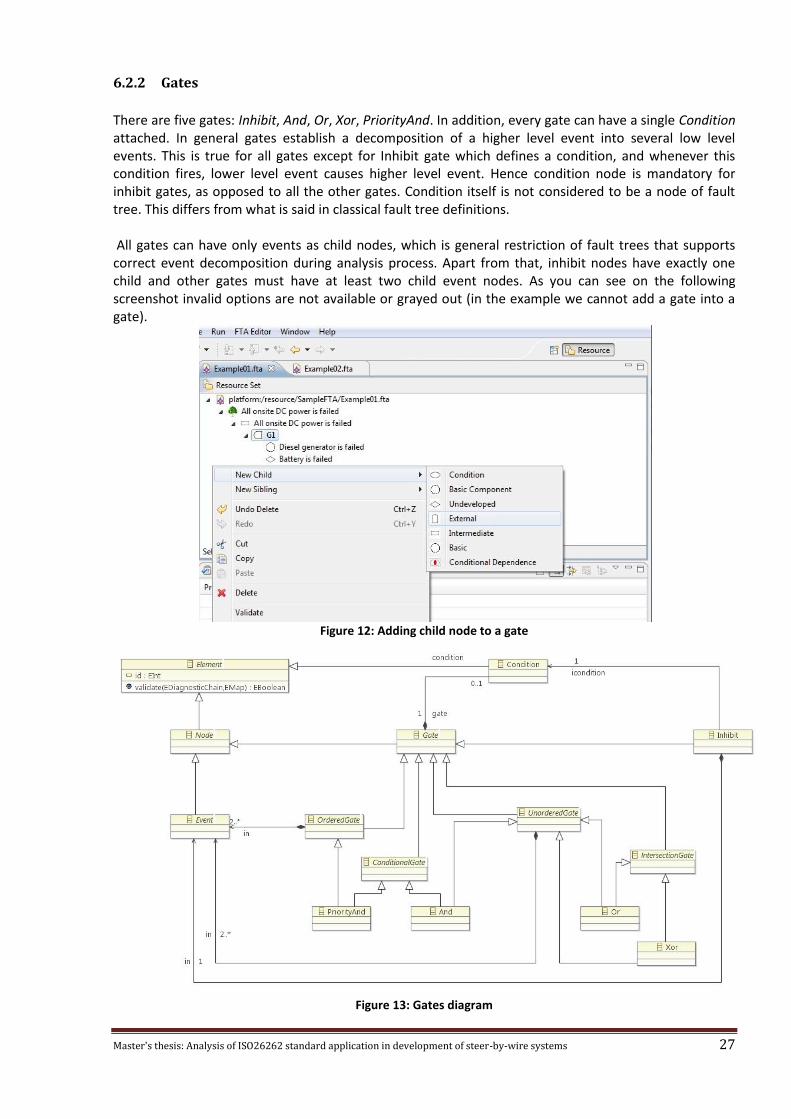
There are five gates: Inhibit, And, Or, Xor, PriorityAnd. In addition, every gate can have a single Condition attached. In general gates establish a decomposition of a higher level event into several low level events. This is true for all gates except for Inhibit gate which defines a condition, and whenever this condition fires, lower level event causes higher level event. Hence condition node is mandatory for inhibit gates, as opposed to all the other gates. Condition itself is not considered to be a node of fault tree. This differs from what is said in classical fault tree definitions. All gates can have only events as child nodes, which is general restriction of fault trees that supports correct event decomposition during analysis process. Apart from that, inhibit nodes have exactly one child and other gates must have at least two child event nodes. As you can see on the following screenshot invalid options are not available or grayed out (in the example we cannot add a gate into a gate).
Figure 12: Adding child node to a gate
Figure 13: Gates diagram

Master's thesis: Analysis of ISO26262 standard application in development of steer-by-wire systems 28
And, Or and Xor nodes do not take into account the order of their child nodes, however PriorityAnd does. Moreover by default all child nodes are considered to be independent of one another. This default behavior can be adjusted by adding dependencies. Dependency nodes do not belong to fault tree and serve as placeholders for dependencies.
Figure 14: Dependence nodes diagram
And along with PriorityAnd gates can have conditional dependence constraints that specify a list of
nodes with probabilities. Each single dependence node defines conditional probability )|(
1
1
n
i
in EEP ,
where nE references current event, and other events are those, being defined before nE in the list of
dependencies. Events, omitted in the list of dependencies, are considered to be independent:
)()|(
1
1
n
n
i
in EPEEP
. Single node is not enough since it does not define a valid constraint. Also
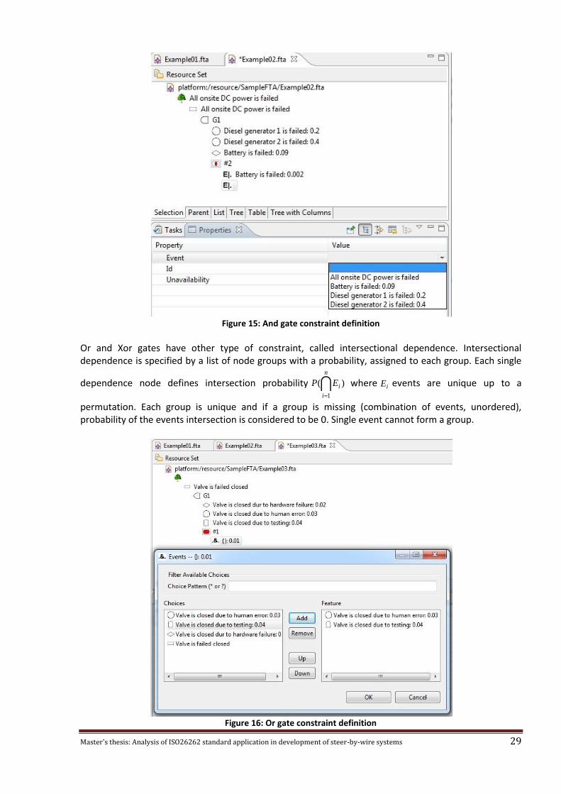
whenever a node is referenced in constraint, its unavailability value will not be used in computation any more, according to semantics of and gate constraint. The following screenshot shows the constraints attached to And gate.
Master's thesis: Analysis of ISO26262 standard application in development of steer-by-wire systems 29
Figure 15: And gate constraint definition
Or and Xor gates have other type of constraint, called intersectional dependence. Intersectional dependence is specified by a list of node groups with a probability, assigned to each group. Each single
dependence node defines intersection probability )(
1
n
i
iEP
where iE events are unique up to a
permutation. Each group is unique and if a group is missing (combination of events, unordered), probability of the events intersection is considered to be 0. Single event cannot form a group.
Figure 16: Or gate constraint definition
Master's thesis: Analysis of ISO26262 standard application in development of steer-by-wire systems 30
Both type of dependencies can reference only events, that are direct child nodes of the corresponding gate. As one can notice gates play a secondary role in fault trees and cannot be referenced directly. For instance, to a sub-tree can start only with event, but not a gate.
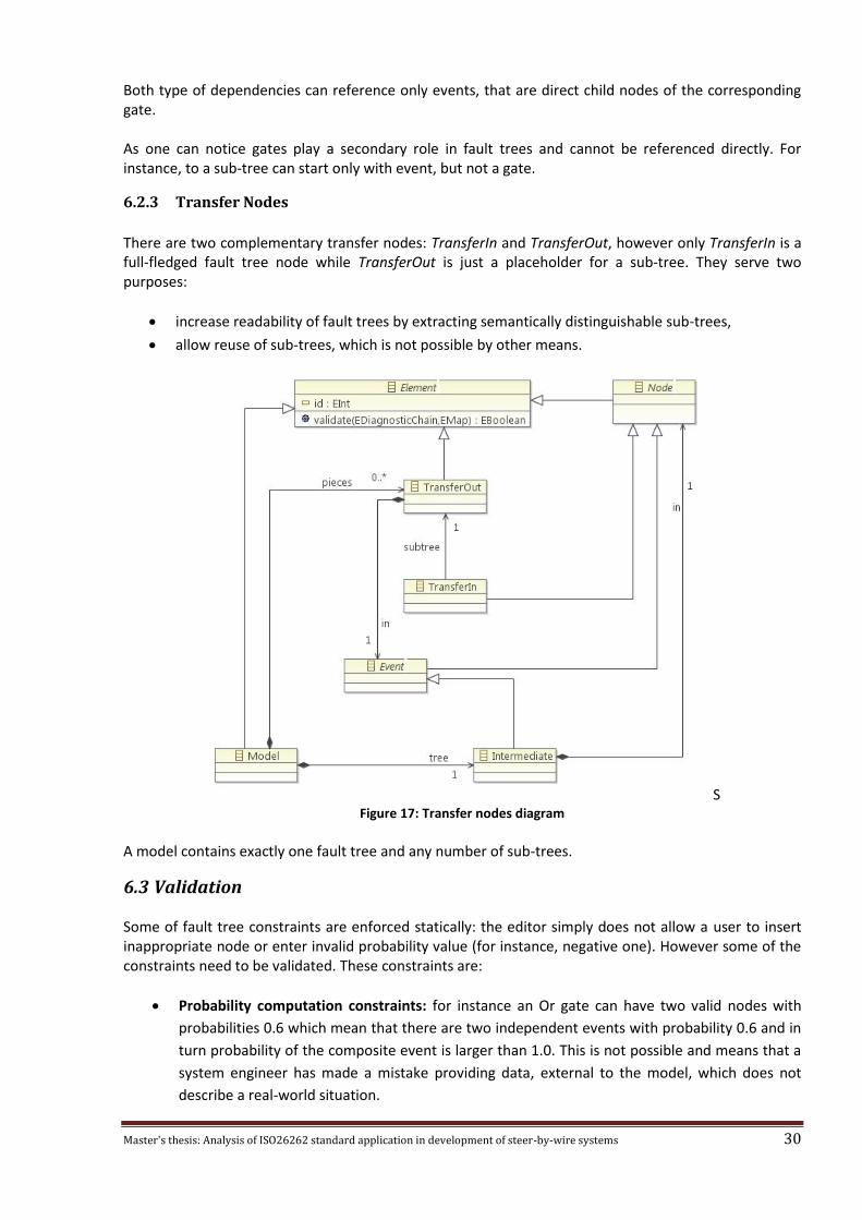
6.2.3 Transfer Nodes
There are two complementary transfer nodes: TransferIn and TransferOut, however only TransferIn is a full-fledged fault tree node while TransferOut is just a placeholder for a sub-tree. They serve two purposes:
increase readability of fault trees by extracting semantically distinguishable sub-trees,
allow reuse of sub-trees, which is not possible by other means.
S Figure 17: Transfer nodes diagram
A model contains exactly one fault tree and any number of sub-trees.
6.3 Validation Some of fault tree constraints are enforced statically: the editor simply does not allow a user to insert inappropriate node or enter invalid probability value (for instance, negative one). However some of the constraints need to be validated. These constraints are:
Probability computation constraints: for instance an Or gate can have two valid nodes with
probabilities 0.6 which mean that there are two independent events with probability 0.6 and in
turn probability of the composite event is larger than 1.0. This is not possible and means that a
system engineer has made a mistake providing data, external to the model, which does not
describe a real-world situation.

Master's thesis: Analysis of ISO26262 standard application in development of steer-by-wire systems 31
Gate constraints: intersectional and conditional dependencies must reference proper gate
nodes and uniqueness constraints must be met.
Required fields: some fields are required in a valid model. They are names for named nodes
and probability values.
Structural constraints: while model is under development, some nodes may be missing,
however for a model to be valid and analyzable, every required child and reference node must
be provided.
Validation is performed manually by user triggering corresponding command. It is possible to perform validation for the whole tree at once, as well as for its parts, keeping number of messages manageable.
Figure 18: Validation screenshot
6.4 Probability computation As has been mentioned before, there are two types of node: those who provide probability values, and those who compute their value from the values of child nodes (IndependentEvent and DependentEvent accordingly). There are five dependent nodes, for which probability computation is not trivial. Assume that G is current gate, E is parent of the gate, iE are gate's child events and C is a condition.
For all type of gates condition is considered to be independent of the gate event and resulting probability is )()()( CPGPEP if condition is provided and )()( GPEP otherwise. )(GP is computed
according to the gate semantics by the following rules:
1. Inhibit gate: )()( 1EPGP and condition is required.
2. And gate: In case of independent events corresponding value is computed by multiplying
probabilities of all the events
n
iiEPGP
1)()( . However in case if some of the events are not
disjoint the value is computed a bit differently. Let us first consider two events case. And gate
corresponds to set intersection in terms of set algebra. This case is shown in the following
diagram:
Master's thesis: Analysis of ISO26262 standard application in development of steer-by-wire systems 32
Figure 19: Intersection of two events
We can compute the probability of intersection in two different ways:
)|()()|()()( 212121 EEPEPEEPEPGP . In the general case we have
n
i
i
j
kk jiEEPGP
1
1
1
)|()( ,
given that nniki ..1}..1:|{ (is a permutation of set n..1 ).
3. PriorityAnd gate: this type of gates distinguish a single permutation. It is evaluated in the same
way as And gate but takes this distinction into account: !
)|(
)(1
1
1
n
EEP
GP
n
i
i
j
kk ji
.
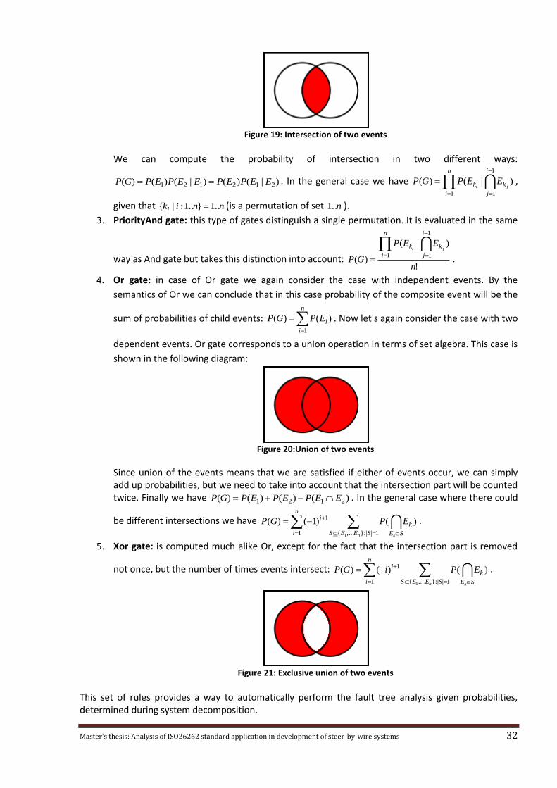
4. Or gate: in case of Or gate we again consider the case with independent events. By the
semantics of Or we can conclude that in this case probability of the composite event will be the
sum of probabilities of child events:
n
i
iEPGP
1
)()( . Now let's again consider the case with two
dependent events. Or gate corresponds to a union operation in terms of set algebra. This case is
shown in the following diagram:
Figure 20:Union of two events
Since union of the events means that we are satisfied if either of events occur, we can simply add up probabilities, but we need to take into account that the intersection part will be counted twice. Finally we have )()()()( 2121 EEPEPEPGP . In the general case where there could
be different intersections we have
n
i SEES SE
ki
n k
EPGP
1 1||:},..,{
1
1
)()1()( .
5. Xor gate: is computed much alike Or, except for the fact that the intersection part is removed
not once, but the number of times events intersect:
n
i SEES SE
ki
n k
EPiGP
1 1||:},..,{
1
1
)()()( .
Figure 21: Exclusive union of two events
This set of rules provides a way to automatically perform the fault tree analysis given probabilities, determined during system decomposition.

Master's thesis: Analysis of ISO26262 standard application in development of steer-by-wire systems 33
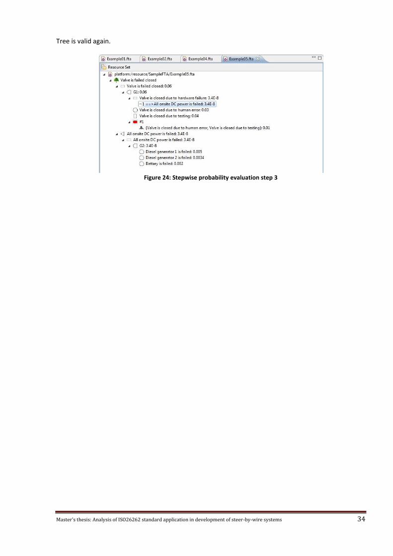
6.5 Stepwise probability evaluation Fault tree analysis can be performed only on a valid tree, however the difference between tree and sub-tree is rather artificial: it is introduced to provide way to break the model into logical components. For a user this means that parts of the tree can be analyzed as soon as they become valid. After every single change a user makes, the change is propagated through the whole tree to its root. This feature increases usability of the application and allows the engineer to spot inconsistencies in the model on the earlier stages of development. The following screenshot shows a valid fault tree with analysis done.
Figure 22: Stepwise probability evaluation step 1
A change is made and the tree becomes invalid, however for the valid parts analysis holds.
Figure 23: Stepwise probability evaluation step 2
Master's thesis: Analysis of ISO26262 standard application in development of steer-by-wire systems 34
Tree is valid again.
Figure 24: Stepwise probability evaluation step 3
Master's thesis: Analysis of ISO26262 standard application in development of steer-by-wire systems 35
7 Conclusion This research had two goals. First was to compare ISO 26262 standard to the processes implemented in a specific project the company has been running. The second one was to develop a tool support for fault tree analysis. Based on the interviews with engineers at the company and on the analysis of both ISO 26262 standard and internal CPAC documentation, the corresponding analysis has been performed. The analysis resulted in a number of detailed suggestions, both optional and mandatory, that will allow to achieve the compliance with the standard. Moreover, the suggestions do not come in conflict with the “agile” software development processes that CPAC is interested into. The recommendations were developed with the interests of the company in mind. Moreover the analysis showed that some of the methodologies CPAC uses are ahead of what is required by the standard. Testing coverage requirements can be thought as an example. Developing safety-critical software is an area with high demands and one way to meet all the constraints is to introduce tools that enforce some of them. Much like with MISRA C standard there are a number of tools that check compliance with its rules, a tool for fault tree analysis has been developed. This tool comes in two flavors: it enforces constraints, declared in fault tree analysis and computes probability values, actually performing the quantitative analysis. The tool is developed as a plugin to Eclipse platform and possesses a rich graphical user interface.
Master's thesis: Analysis of ISO26262 standard application in development of steer-by-wire systems 36
8 Future improvements Set of recommendations on how to adjust currently adopted processes to the demands of oncoming ISO 26262 standard has been developed as part of this work. However mainly the focus has been on the software development part. Considering that CPAC Systems AB produces whole systems, that comprise of both software and hardware parts, the company will be in demand of further analysis. This analysis might focus on the other parts of the standard. Besides current ISO 26262 standard is targeted on road vehicles which means that this work needs to be revised whenever a standard, specific to industrial vehicles, will emerge. There are a number of commercial tools that support fault tree analysis and other types of analysis like failure mode and effect analysis and others. However there are several disadvantages of using these tools:
Certification. ISO 26262 standard as well as other similar standards require that whenever any tool is used, evidence of its correct functioning must be provided. Both successful usage results and actual code reviews and tests count as valid evidence, but for a third party software only the forma is actually available.
Extensibility. Tool is built as a plugin to Eclipse platform. This platform is highly extensible on its own and enforces model-driven development. Resulting tool has inherited extensibility property and can be enriched with other types of analysis like failure mode and effect analysis or cut-set analysis. The most important thing here is that all analysis methods work with the fault tree. Which means that the most important value of the tool is that is provides fault tree model application interface and user interface for building valid fault trees.
Customizability. It is possible to adjust the tool to the needs of a specific project. This is clearly impossible with the use of third party tools.
Cost. Development of safety-critical embedded software is rather specific area and software tools for it are usually quite expensive. Also in the case if company decides to buy a third party tool, current project will allow to make a comparison of the two solutions and better indicate the value of the commercial tool specifically for CPAC.
Considering these points obviously there is a room for the tool improvement. Additionally thorough testing is required to guarantee the required level of quality confidence.
Master's thesis: Analysis of ISO26262 standard application in development of steer-by-wire systems 37
9 References [1] ISO 26262 (2010), "Road vehicles — Functional safety — Part 1: Vocabulary", Geneva 20, Switzerland.
[2] ISO 26262 (2010), "Road vehicles — Functional safety — Part 2: Management of functional safety", Geneva 20, Switzerland.
[3] ISO 26262 (2010), "Road vehicles — Functional safety — Part 3: Concept phase", Geneva 20, Switzerland.
[4] ISO 26262 (2010), "Road vehicles — Functional safety — Part 4: Product development at the system level",Geneva 20, Switzerland.
[5] ISO 26262 (2010), "Road vehicles — Functional safety — Part 5: Product development at the hardware level",Geneva 20, Switzerland.
[6] ISO 26262 (2010), "Road vehicles — Functional safety — Part 6: Product development: software level",Geneva 20, Switzerland.
[7] ISO 26262 (2010), "Road vehicles — Functional safety — Part 7: Production and operation",Geneva 20, Switzerland.
[8] ISO 26262 (2010), "Road vehicles — Functional safety — Part 8: Supporting processes ",Geneva 20, Switzerland.
[9] ISO 26262 (2010), "Road vehicles — Functional safety — Part 9: ASIL-oriented and safety-oriented analyses",Geneva 20, Switzerland.
[10] ISO 26262 (2010), "Road vehicles — Functional safety — Part 10: Guideline on ISO 26262 ",Geneva 20, Switzerland.
[11]MISRA (Ed. 2, 2008), "MISRA-C:2004- Guidelines for the Use of the C Language in Critical Systems ", Warwickshire, UK.
[12] Agile Manifesto, http://www.agilemanifesto.org , last accessed: 2010-03-21.
[13] Mack N., Woodsong C., Macqueen K., Guest G., Namey E. (2005), Qualitative Research Methods: A Data Collector’s Field Guide (Family Health International, Research Triangle Park, North Carolina, USA.
[14]Dale T. Griffee, Research Tips: Interview Data Collection, Journal of Developmental Education, Volume 28, Number 3, spring 2005.
[15]Frank Budinsky, David Steinberg, Ed Merks, Raymond Ellersick, Timothy J. Grose (2003), "Eclipse Modeling Framework: A Developer's Guide", Addison Wesley.
[16] W. E. Vesely, F. F. Goldberg, N. H. Roberts, D. F Haasl (1981), "Fault Tree Handbook", U.S. Nuclear Regulatory Commission, Washington, D.C., USA.
[17] MIL-HDBK-338B (1998), "Fault Tree Analysis: Electronic Reliability Design Handbook", U.S. Department of Defense
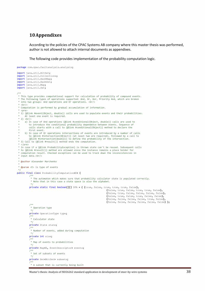
Master's thesis: Analysis of ISO26262 standard application in development of steer-by-wire systems 38
10 Appendixes According to the policies of the CPAC Systems AB company where this master thesis was performed, author is not allowed to attach internal documents as appendixes. The following code provides implementation of the probability computation logic.
package com.cpac.faultanalysis.analysis; import java.util.BitSet; import java.util.Collections; import java.util.HashMap; import java.util.HashSet; import java.util.Map; import java.util.Set; /** * This type provides computational support for calculation of probability of compound events. * The following types of operations supported: And, Or, Xor, Priority And, which are broken * into two groups: And operations and Or operations. <br/> * <br/> * Computation is performed by gradual accumulation of information. * <pre> * 1) {@link #event(Object, double)} calls are used to populate events and their probabilities. * At least one event is required. * 2) <br/> * a) In case of And operations {@link #conditional(Object, double)} calls are used to * to introduce the conditional probability dependence between events. Sequence of * calls starts with a call to {@link #conditional(Object)} method to declare the * first event. * b) In case of Or operations intersections of events are introduced by a number of calls * to {@link #intersection(Object)} (at least two are required), followed by a call to * {@link #intersection(double)} to define the probability of the intersection. * 3) Call to {@link #result()} method ends the computation. * </pre> * In case if a {@link ProbabilityException} is thrown state can't be reused. Subsequent calls * to {@link #result()} method are allowed since the instance remains a place holder for * computation result. Checked exceptions can be used to track down the inconsistencies in * input data.<br/> * * @author Alexander Marchenko * * @param <E> is type of events */ public final class ProbabilityComputation<E> { /** * The automaton which makes sure that probability calculator state is populated correctly. * Note that in this case a state space is also the alphabet. */ private static final boolean[][] DFA = { {true, false, true, true, true, false}, {false, true, false, true, true, false}, {false, true, false, false, false, false}, {false, true, false, true, false, false}, {false, false, false, false, true, false}, {false, false, false, false, false, false} }; /** * Operation type */ private OperationType type; /** * Calculator state */ private State state; /** * Number of events, added during computation */ private int size; /** * Map of events to probabilities */ private Map<E, EventDescriptor> events; /** * Set of subsets of events */ private Set<BitSet> subsets; /** * A subset that is currently being built

Master's thesis: Analysis of ISO26262 standard application in development of steer-by-wire systems 39
*/ private BitSet subset; /** * Result of the computation */ private double result; /** * Changes the state of calculator making sure that data is collected correctly. * * @param target is the new state * @return whether the actual state has been changed */ private boolean proceed(State target) { if (!DFA[state.ordinal()][target.ordinal()]) { throw new IllegalStateException("Invalid transition from " + state + " to " + target); } if (state == target) { return false; } else { state = target; return true; } } /** * Convenience method ensures that object is not null * * @param o is a value * @exception NullPointerException is case if o is null */ private void ensureNotNull(Object o) { if (o == null) { throw new NullPointerException(); } } /** * Convenience method ensures that probability is valid * * @param probability is a double * @exception IllegalArgumentException in case if value is not within [0.0 .. 1.0] */ private void ensureProbabilityIsValid(double probability) { if (!isValid(probability)) { throw new IllegalArgumentException("Invalid probability value : " + probability); } } /** * Sets the state to error, preventing from exploiting the invalid state of computation * * @param e is an exception * @return e */ private ProbabilityException error(ProbabilityException e) { this.state = State.ERROR; return e; } /** * Creates probability computation object * * @param type is the operation */ public ProbabilityComputation (OperationType type) { ensureNotNull(type); this.type = type; this.state = State.GATHERING_EVENTS; this.size = 0; this.events = new HashMap<E, EventDescriptor>(); if (!type.isAnd()) { this.subsets = new HashSet<BitSet>(); } this.subset = null; this.result = type.isAnd() ? 1.0 : 0.0; } /** * gives the type of probability computation * * @return operation type */ public OperationType type() { return type; } /** * adds a unique event and its probability * * @param event is not <code>null</code> and will be put into a hash table * @param probability is in [0.0 .. 1.0] * @throws ProbabilityException if there is already such event in the set
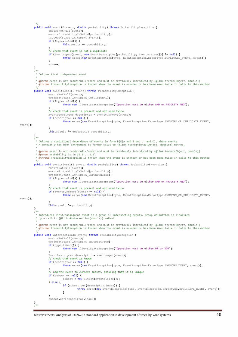
Master's thesis: Analysis of ISO26262 standard application in development of steer-by-wire systems 40
*/ public void event(E event, double probability) throws ProbabilityException { ensureNotNull(event); ensureProbabilityIsValid(probability); proceed(State.GATHERING_EVENTS); if (!type.isAnd()) { this.result += probability; } // check that event is not a duplicate if (events.put(event, new EventDescriptor(probability, events.size())) != null) { throw error(new EventException(type, EventException.ErrorType.DUPLICATE_EVENT, event)); } size++; } /** * Defines first independent event. * * @param event is not <code>null</code> and must be previously introduced by {@link #event(Object, double)} * @throws ProbabilityException is thrown when the event is unknown or has been used twice in calls to this method */ public void conditional(E event) throws ProbabilityException { ensureNotNull(event); proceed(State.GATHERING_CONDITIONAL); if (!type.isAnd()) { throw new IllegalStateException("Operation must be either AND or PRIORITY_AND"); } // check that event is present and not used twice EventDescriptor descriptor = events.remove(event); if (descriptor == null) { throw error(new EventException(type, EventException.ErrorType.UNKNOWN_OR_DUPLICATE_EVENT, event)); } this.result *= descriptor.probability; } /** * Defines a conditional dependence of events in form P(E|A and B and .. and D), where events * A through D has been introduced by former calls to {@link #conditional(Object, double)} method. * * @param event is not <code>null</code> and must be previously introduced by {@link #event(Object, double)} * @param probability is in [0.0 .. 1.0] * @throws ProbabilityException is thrown when the event is unknown or has been used twice in calls to this method */ public void conditional(E event, double probability) throws ProbabilityException { ensureNotNull(event); ensureProbabilityIsValid(probability); proceed(State.GATHERING_DEPENDENCIES); if (!type.isAnd()) { throw new IllegalStateException("Operation must be either AND or PRIORITY_AND"); } // check that event is present and not used twice if (events.remove(event) == null) { throw error(new EventException(type, EventException.ErrorType.UNKNOWN_OR_DUPLICATE_EVENT, event)); } this.result *= probability; } /** * Introduces first/subsequent event in a group of intersecting events. Group definition is finalized * by a call to {@link #intersection(double)} method. * * @param event is not <code>null</code> and must be previously introduced by {@link #event(Object, double)} * @throws ProbabilityException is thrown when the event is unknown or has been used twice in calls to this method */ public void intersection(E event) throws ProbabilityException { ensureNotNull(event); proceed(State.GATHERING_INTERSECTION); if (type.isAnd()) { throw new IllegalStateException("Operation must be either OR or XOR"); } EventDescriptor descriptor = events.get(event); // check that event is known if (descriptor == null) { throw error(new EventException(type, EventException.ErrorType.UNKNOWN_EVENT, event)); } // add the event to current subset, ensuring that it is unique if (subset == null) { subset = new BitSet(events.size()); } else { if (subset.get(descriptor.index)) { throw error(new EventException(type, EventException.ErrorType.DUPLICATE_EVENT, event)); } } subset.set(descriptor.index); } /**
Master's thesis: Analysis of ISO26262 standard application in development of steer-by-wire systems 41
* Finalizes a group of intersecting events by defining their probability. * * @param probability is in [0.0 .. 1.0] * @throws ProbabilityException is thrown if there were no events or the intersection has been defined before */ public void intersection(double probability) throws ProbabilityException { ensureProbabilityIsValid(probability); proceed(State.GATHERING_DEPENDENCIES); if (type.isAnd()) { throw new IllegalStateException("Operation must be either OR or XOR"); } // keep track of subsets if (subset == null) { throw error(new EmptyEventSetException(type, true)); } // check that subset is unique (singleton subsets are already defined as events) if (subset.cardinality() == 1 || !subsets.add(subset)) { // gather the subset Set<E> events = new HashSet<E>(this.size); for (Map.Entry<E, EventDescriptor> entry : this.events.entrySet()) { if (subset.get(entry.getValue().index)) { events.add(entry.getKey()); } } throw error(new NonUniqueEventSubSetException(type, events)); } // add the intersection probability int count = subset.cardinality(); double k = count % 2 == 0 ? -1.0 : 1.0; if (type == OperationType.XOR) { k *= (double) count; } result += k * probability; subset = null; } /** * Computes the result of operation application. * * @return resulting probability * @throws ProbabilityException is thrown in case if there were no events defined or resulting value is not a probability */ public double result() throws ProbabilityException { // perform the computation only once, after that result remains available if (proceed(State.DONE)) { // probability computation could be performed with at least one operand if (size == 0) { throw error(new EmptyEventSetException(type, false)); } // all events, not covered by conditions, are considered independent if (type.isAnd()) { for (EventDescriptor value : events.values()) { result *= value.probability; } // consider permutations and divide by n! if (type == OperationType.PRIORITY_AND) { for (int i = 2; i <= size; i++) { result /= (double) i; } } } // dispose temporary data this.events = null; this.subsets = null; this.subset = null; } if (!isValid(result)) { throw error(new InvalidProbabilityException(type, result)); } return result; } /** * Displays operation type, state of computation and result * * @see java.lang.Object#toString() */ @Override public String toString() { return "operation type = " + type + ", state = " + state + ", result = " + result; } /** * Checks that value belongs to [0.0 .. 1.0] hence is a valid probability value * * @param value is a double value * @return whether it is a valid probability value */
Master's thesis: Analysis of ISO26262 standard application in development of steer-by-wire systems 42
public static final boolean isValid(double value) { return 0.0 <= value && value <= 1.0; } /** * Defines all possible operations */ public static enum OperationType { /** * Represents an intersection of events and is computed by P(A)P(B|A)P(C|A and B)... */ AND, /** * Represents a union of events and is computed by P(A)+P(B)+P(C)-P(A and B)-P(A and C)-P(B and C)+P(A and B and C) */ OR, /** * Represents a union of disjoint parts of events and is computed by P(A)+P(B)+P(C)-2P(A and B)-2P(A and C)-2P(B and C)+3P(A and B and C) */ XOR, /** * Represents an intersection of events when a specific permutation matters and is computed by P(A and B and C) / 3! */ PRIORITY_AND; /** * Distinguishes between And and Or operations * * @return whether this is an And operation */ public boolean isAnd() { return this == AND || this == PRIORITY_AND; } } /** * Introduces an exception, that can occur during probability computation. */ public static abstract class ProbabilityException extends Exception { /** * Serial version */ private static final long serialVersionUID = 9200443022773996544L; /** * Operation, during which an error occurred */ private OperationType operation; /** * Creates exception * * @param operation is a constant * @param message is a description string */ public ProbabilityException (OperationType operation, String message) { super(message); this.operation = operation; } /** * Operation, during which an error occurred * * @return constant */ public OperationType operation() { return operation; } } /** * Event exceptions are thrown when sets of events, used for * probability computation, do not describe a valid formula */ public static class EventException extends ProbabilityException { /** * Serial version */ private static final long serialVersionUID = -4405487449358891842L; /** * Type of error */ private ErrorType error; /** * Event that triggered the error */ private Object event; /** * Create the error *

Master's thesis: Analysis of ISO26262 standard application in development of steer-by-wire systems 43
* @param operation is a constant * @param error is a constant * @param event is an event */ public EventException(OperationType operation, ErrorType error, Object event) { super(operation, error.message + event); this.error = error; this.event = event; } /** * Get type of error * * @return is a error constant */ public ErrorType error() { return error; } /** * Get event that triggered the error * * @return is an event */ public Object event() { return event; } /** * Introduces a number of errors */ public enum ErrorType { /** * Event, used in constraint is not declared */ UNKNOWN_EVENT("Event, used in constraint is not declared : "), /** * Event is used twice while defining constraints */ DUPLICATE_EVENT("Event is used twice while defining constraints : "), /** * Event is either not declared or is used twice */ UNKNOWN_OR_DUPLICATE_EVENT("Event is either not declared or is used twice : "); /** * Error message */ public final String message; /** * creates a constant * * @param message is some string */ private ErrorType(String message) { this.message = message; } }; } /** * Sets and subsets of events can't be empty. Otherwise this exception is thrown. */ public static class EmptyEventSetException extends ProbabilityException { /** * Serial version */ private static final long serialVersionUID = 7719585903447029507L; /** * Distinguishes set from subset condition */ private boolean isSubSet; /** * Creates exception * * @param operation is constant * @param isSubSet distinguishes set from subset condition */ public EmptyEventSetException(OperationType operation, boolean isSubSet) { super(operation, isSubSet ? "Subset of events is empty" : "Set of events is empty"); this.isSubSet = isSubSet; }
Master's thesis: Analysis of ISO26262 standard application in development of steer-by-wire systems 44
/** * Distinguishes set from subset condition * * @return boolean value */ public boolean isSubSet() { return isSubSet; } } /** * When a subset of events is used more then twice defining constraint, this exception is thrown. */ public static class NonUniqueEventSubSetException extends ProbabilityException { /** * Serial version */ private static final long serialVersionUID = 438736623616920733L; /** * Set of events encountered twice */ private Set<Object> events; /** * Create exception * * @param operation is a constant * @param events is collection of events */ public NonUniqueEventSubSetException(OperationType operation, Set<? extends Object> events) { super(operation, "Subset of event has been encountered twice"); this.events = Collections.unmodifiableSet(events); } /** * Set of events encountered twice * * @return unmodifiable set */ public Set<Object> events() { return events; } } /** * During a probability computation an error could occur: resulting value is outside of [0.0 .. 1.0]. * In this case this error is thrown. */ public static class InvalidProbabilityException extends ProbabilityException { /** * Serial version */ private static final long serialVersionUID = -1857640398893155872L; /** * Invalid probability value */ private double value; /** * Create exception * * @param operation is a constant * @param value is a double value */ public InvalidProbabilityException(OperationType operation, double value) { super(operation, "Computation resulted in an invalid probability : " + value); this.value = value; } /** * Invalid probability value * * @return a double */ public double value() { return value; } } /** * Describes the internal states of computation */ private enum State { GATHERING_EVENTS, GATHERING_DEPENDENCIES, GATHERING_CONDITIONAL, GATHERING_INTERSECTION, DONE, ERROR } /** * A record that stored probability of event and its index number (upon insertion) */ private class EventDescriptor {
Master's thesis: Analysis of ISO26262 standard application in development of steer-by-wire systems 45
/** * Is a valid probability */ public final double probability; /** * Is index of event, >= 0 */ public final int index; /** * create record * * @param probability is a valid probability * @param index is index of event, >= 0 */ public EventDescriptor(double probability, int index) { assert 0.0 <= probability && probability <= 1.0; assert 0 <= index; this.probability = probability; this.index = index; } @Override public String toString() { return "index = " + index + ", probability = " + probability; } } }