Embed Size (px)
Citation preview

N A S A TECHNICAL NOTE N A S A TN c - 103
ANALYSIS OF LOW-TEMPERATURE DIRECT-CONDENSING VAPOR-CHAMBER FIN A N D CONDUCTING FIN RADIATORS
by Henry C. Haller, Bruce G, Lindow, a n d Bruce M . Azcer
Lewis Research Center Cleveland, 0 h io f .
a t
N A T I O N A L A E R O N A U T I C S A N D S P A C E A D M I N I S T R A T I O N - W A S H I N G T O N , D . C . -' N O V E M B E R 1965 ,i% , . ,
https://ntrs.nasa.gov/search.jsp?R=19660001459 2018-06-11T12:36:26+00:00Z

TECH Ll0RARY KAFB, NM
I 111111 11111 1111 lllll lllll IIIII 11111 Ill1 Ill
ANALYSIS O F LOW-TEMPERATURE DIRECT-CONDENSING VAPOR-
CHAMBER FIN AND CONDUCTING FIN RADIATORS
By Henry C. Haller, Bruce G. Lindow, and Bruce M. Auer
Lewis Research Center Cleveland, Ohio
NATIONAL AERONAUTICS AND SPACE ADMINISTRATION
For sale by the Clearinghouse for Federal Scientific and Technical Information Springfield, Virginia 22151 - Price $3.00

CONTENTS
Page SUMMARY . . . . . . . . . . . . . . . . . . . . . . . . . . . . . . . . . . . . . . . 1
INTRODUCTION . . . . . . . . . . . . . . . . . . . . . . . . . . . . . . . . . . . . 2
ANALYSIS . . . . . . . . . . . . . . . . . . . . . . . . . . . . . . . . . . . . . . . 3 Radiator Configuration . . . . . . . . . . . . . . . . . . . . . . . . . . . . . . . 3
Solid fin geometries . . . . . . . . . . . . . . . . . . . . . . . . . . . . . . . 4 Vapor- chamber f in geometry . . . . . . . . . . . . . . . . . . . . . . . . . . 5 Meteoroid damage . . . . . . . . . . . . . . . . . . . . . . . . . . . . . . . . 6
Design Conditions . . . . . . . . . . . . . . . . . . . . . . . . . . . . . . . . . 6 Calculation Procedure and Inputs . . . . . . . . . . . . . . . . . . . . . . . . . 6
VAPOR-CHAMBERFIN-TUBE CHARACTERISTICS . . . . . . . . . . . . . . . . . 8 Radiator Weight . . . . . . . . . . . . . . . . . . . . . . . . . . . . . . . . . . 8 Radiator Geometry . . . . . . . . . . . . . . . . . . . . . . . . . . . . . . . . . 10
Planform area . . . . . . . . . . . . . . . . . . . . . . . . . . . . . . . . . . 10 Tube block armor thickness . . . . . . . . . . . . . . . . . . . . . . . . . . . 12
Fin thickness . . . . . . . . . . . . . . . . . . . . . . . . . . . . . . . . . . . 13 Number of f in segments . . . . . . . . . . . . . . . . . . . . . . . . . . . . . 13
Capillary Flow Requirements . . . . . . . . . . . . . . . . . . . . . . . . . . . 15 Radiator Thermal Degradation . . . . . . . . . . . . . . . . . . . . . . . . . . . 16
L/R, r a t i o . . . . . . . . . . . . . . . . . . . . . . . . . . . . . . . . . . . . 12
COMPARISON OF RESULTS. . . . . . . . . . . . . . . . . . . . . . . . . . . . . . 19 Radiator Weight. . . . . . . . . . . . . . . . . . . . . . . . . . . . . . . . . . . 20 Radiator Geometry . . . . . . . . . . . . . . . . . . . . . . . . . . . . . . . . . 23
Planform area . . . . . . . . . . . . . . . . . . . . . . . . . . . . . . . . . . 23 Number of tubes . . . . . . . . . . . . . . . . . . . . . . . . . . . . . . . . . 24 Fin thickness . . . . . . . . . . . . . . . . . . . . . . . . . . . . . . . . . . . 26 L / R ~ Ratio . . . . . . . . . . . . . . . . . . . . . . . . . . . . . . . . . . . 26 Tube armor thickness . . . . . . . . . . . . . . . . . . . . . . . . . . . . . . 28 Panel aspect ratio . . . . . . . . . . . . . . . . . . . . . . . . . . . . . . . . 28
Thermal Characteristics . . . . . . . . . . . . . . . . . . . . . . . . . . . . . . 28

Comparison with High-Power-Level Results . . . . . . . . . . . . . . . . . . . . 3 1 Radiator weight . . . . . . . . . . . . . . . . . . . . . . . . . . . . . . . . . . . 32 Radiator geometry . . . . . . . . . . . . . . . . . . . . . . . . . . . . . . . . . 32 T h e r m a l degradation . . . . . . . . . . . . . . . . . . . . . . . . . . . . . . . 33
SUMMARY O F RESULTS . . . . . . . . . . . . . . . . . . . . . . . . . . . . . . . . 33
APPENDIXES A.SYMB0LS . . . . . . . . . . . . . . . . . . . . . . . . . . . . . . . . . . . . . 36 B . HEAT-TRANSFERANALYSIS . . . . . . . . . . . . . . . . . . . . . . . . . 39 C . VAPOR-CHAMBER FIN-TUBE THERMAL ANALYSIS . . . . . . . . . . . . . 45 D . RADIATOR WEIGHT AND GEOMETRY . . . . . . . . . . . . . . . . . . . . . 48 E . PRESSURE DROP . . . . . . . . . . . . . . . . . . . . . . . . . . . . . . . . 53
REFERENCES . . . . . . . . . . . . . . . . . . . . . . . . . . . . . . . . . . . . . . 54
ii

ANALYSIS OF LOW-TEMPERATURE DIRECT-CONDENSING VAPOR-
CHAMBER FIN AND CONDUCTING FIN RADIATORS
by H e n r y C. Haller, B ruce G. Lindow, and B r u c e M.Auer
Lewis Research Center
SUMMARY
An analytical comparison of flat, direct-condensing f inned-tube space radiators em- ploying vapor-chamber, double, and central fin-tube geometries was made for a low power output, low-temperature Rankine space power electric generating system. The descriptive equations for the radiator investigation included in addition to the heat- transfer analysis, consideration of vapor and liquid headers, pressure drop in the headers and radiator tubes, meteoroid protection for the tubes, headers, and vapor- chamber fins, and temperature drop in the tube armor. The heat-transfer, weight, and geometry characteristics of the three radiator fin-tube configurations were determined over a wide range of variables for design conditions descriptive of a 30-kilowatt powerplant that used steam as the thermodynamic cycle fluid. The thermal degradation of the vapor-chamber fin-tube radiator due to puncture of the individual fin segments, and the vapor chamber heat transfer and capillary fluid flow requirements were also investigated.
For the example case chosen, which employed a tube meteoroid nonpenetration probability of 0.90, the vapar-chamber fin radiator was clearly not superior in heat re- jection per unit weight to the central and double fin geometries. The largest values of heat rejection per unit weight were obtained for the double-fin geometry radiator.
substantially greater heat rejection per unit weight compared to the central f in-tube radiator (80 to 130 percent increase) over the entire range of tube inner diameters from 0.075 to 0.375 inch. For a ratio of tube block sidewall thickness to full armor thickness equal to 0.5, the vapor-chamber f i n radiator was also substantially better than the double- fin radiator (order of 20 to 70 percent greater in maximum heat rejection per unit weight] It was only for the case of ratio of sidewall thickness to armor thickness approaching zero that the vapor-chamber fin radiator was not superior to the double fin radiator.
vapor-chamber fin-tube radiator had a substantially smaller planform area (20 to 40 per- cent), fewer radiator tubes, and larger tube inner diameters than the other two fin-tube geometries. The double fin-tube radiator at minimum weight has a major disadvantage because the fins are very thin thus posing possible fabrication and structural problems.
For a tube nonpenetration probability of 0.995, the vapor-chamber fin radiator had a
Radiator geometry considerations indicated, that at the minimum weight condition, the

INTROD UCTl ON Heat rejection to space from electric power generating systems operating at rela-
tively low cycle temperatures requires radiators of large planform area. Radiators designed for the rejection of waste heat generally employ fins as extended radiation heat- transfer surfaces between fluid- carrying tubes. Such an arrangement reduces the amount of the overall radiator surface occupied by flow passages and thereby reduces the area vulnerable to critical damage from impacting meteoroids.
The central fin-tube geometry, which consists of a number of parallel tubes sepa- rated by solid fins located in the plane of the tube centers, is often considered. Analyses of the solid-conducting central fin-tube radiators are given in references 1 to 6. Other solid-conducting fin-tube arrangements, such as the double fin-tube and open sandwich fin-tube radiators, a r e analyzed in references 7 and 8.
ators along with decreasing weight and planform area, the vapor- chamber f in-tube con - cept was analyzed and compared to the central and double fin-tube geometries for high- power-level, high-temperature-level radiators in reference 9. The vapor- chamber fin concept proposes to reduce radiator weight and area by providing for an essentially iso- thermal fin between tubes: the single solid fin is replaced by a double-wall fin that forms a hollow chamber between tubes. A working fluid in the chamber can then be boiled off the tube surfaces and condensed on the fin surfaces to produce a fin of constant tempera- ture and high radiating effectiveness. Condensate is then returned to the boiling surface by capillary pumping, which is essentially insensitive to gravity (ref. 10).
The results of reference 9 indicate that the vapor-chamber fin-tube radiator concept results in a sizable weight advantage over both the central fin-tube and the double fin- tube configurations at high power and temperature levels. The vapor- chamber fin-tube radiator was also shown to have a substantially smaller planform area, fewer number of radiator tubes, and larger tube inner diameters at minimum weight than the other two fin-tube geometries.
chamber fin radiator in a high-temperature, high-power-level system (ref. 9) also hold at low power and temperature levels. In order to carry out this objective, numerical calculations were conducted for the three fin-tube geometries as planer direct- condensing radiators employing design inputs characteristic of a 30-kilowatt Rankine electric power- generating cycle using steam as the working fluid. Radiator heat transfer, weight, and geometry characteristics were determined for a wide range of variables such as tube in- side diameter, fin profile ratio, ratio of tube-block sidewall thickness to armor thickness in the case of the double and vapor fin-tube geometries, conductance parameter for the solid fin radiators, fin vapor- chamber boiling heat-transf er coefficient, ratio of boiling to condensing heat-transfer coefficients for the vapor-chamber fin, vapor-chamber fin
In order to find a means of increasing the radiating effectiveness of the solid fin radi-
This investigation was made to see if the relative advantages obtained for the vapor-
2

Fin-.,
Radiator tube-.,
Vapor header-,,
Liquid header-\\
7 i
Figure 1. - Four-panel fin-tube radiator
capillary mechanism weight, and vapor- chamber fin segment planform area. The vapor-chamber fin-tube configuration was initially investigated to determine
major influencing factors and to establish representative conditions for comparison with the other fin-tube geometries. Boiling heat flux and capillary flow requirements for the vapor- chamber fin were also determined. In addition, the one-dimensional radiating effectiveness of a punctured segment of a vapor-chamber fin, which then acts as a solid- conducting fin, was determined to indicate the maximum loss in effectiveness that might be encountered with this configuration.
The two solid-conducting fin radiators were investigated and then compared with the vapor-chamber fin-tube radiator over the same range of tube inner diameters for the same materials, cycle conditions, tube and header pressure drops, and meteoroid prot e ct ion criteria
ANA LY S I S Radiator Con f ig u rat ion
The general radiator panel configuration considered for the analysis is shown in fig- ure 1. The configuration illustrated is a flat plate direct-condensing radiator that radi- ates hemispherically to space from both sides and is applicable to Rankine power cycles. Exhaust from the cycle turbine is distributed to the finned tubes by the central vapor header. The heat radiated from the vapor header and finned tubes causes the vapor to condense. The condensate is then subcooled and collected in the outer liquid headers be- fore being sent to the condensate pump.
The vapor header is assumed to be a hollow paraboloid whose wall consists of a 0.030 inch liner and meteoroid protection armor of the same thickness as that required
3

I IrT" Armor 7,
f i ,-Fin P A r Liner ti
C R o - L 2L ~
(a) Central f in-tube configuration.
I r Fin I I
/ I
/ I 4
t
21 -~ Tube l iner 7\ -Rb-
\ /
t t
1
Tube 2L- I- armor blockJ/' Po 2L"-
'
\ I 4 "a I uue Illlt.1 7
\ /
c I
t Ii '7
(b) Double fin-tube with variable tube-block sidewall thickness.
Lonqitudinal bulkhead , ,r Vapor chamber
L-- Tf 2L"-
Tube armor block'
(c) Vapor chamber f in-tube with variable tube block s idwa l l thickness.
Figure 2. - Cross sections of radiator f in-tube configurations.
by the tubes. The parabolic shape is intended to produce a constant velocity in the header. For simplicity, the liquid header was designed with a constant diameter at a prescribed fluid pressure drop. The liner for the liquid header has the same thickness as the tube liners (0.020 in. ) and is independent of header diameter. The liquid header also has meteoroid armor thickness equal t o that obtained for the tubes. No heat radiation or sub- cooling is credited to the liquid header.
Solid fin geometries. - The detailed cross-sectional drawings of the three geomet- ries to be compared a r e shown in figure 2. The central fin tube geometry of figure 2(a) consists of a rectangular fin attached to two round tubes in which a liner is inserted.
4

..- Tube Tube liner’/ block
Figure 3. - Isometric d r w i n g of vapor-chamber fin-tube configuration.
The double fin-tube with variable tube sidewall thickness 6 , is composed of a tube liner inserted in an armor block to provide meteoroid protection and two rectangular fins (fig. 2(b)). (Symbols are defined in appendix A. ) This geometry offers some advantages because it can act as a bumper screen that will afford protection against meteoroid im- pact damage on the tube block sidewalls.
Vapor- chamber fin geometry. - The vapor-chamber fin-tube geometry of figure 2(c) consists of a tube liner inserted in an armor block to provide meteoroid protection and two rectangular fins forming a sealed, enclosed chamber between adjacent tubes. A capillary flow medium such as narrow grooves, woven wire mesh, or fibrous matt lines the inner surfaces of the fin chamber and is saturated with a heat-transport fluid. The fluid used should provide a saturation pressure at the chamber operating tempera- ture that is compatible with the chamber construction.
loss of transport fluid occurs, the long fin chambers are divided into a number of sealed compartments by a longitudinal and numerous transverse bulkheads (fig. 3) in order to localize the effect of a puncture. The thickness for both longitudinal and transverse bulk- heads was taken as 0.020 inches. The exposed area of each compartment Aseg, which determined the total number of f i n compartments N, was designated an independent vari- able. The thickness of the fin t was based on a given probability that a certain percent- age of the compartments wmld remain unpunctured at the end of the design lifetime of the radiator. The actual dimensions of the fin result from an optimization procedure that includes meteoroid protection considerations for the fin. The calculation procedure of reference 11 is used for the meteoroid puncture criterion with vulnerable area taken
Inasmuch as the vapor chamber will lose its heat-transport action if a puncture and
5

to be the exposed surface of a fin segment.
liner can be damaged by impacting meteoroids in two general ways. The first is by any primary impacts occurring on the outer exposed surfaces of the tube block. These im- pacts are assumed to obey the conventional armor penetration and damage relations developed for tubes. Accordingly, the tube armor block thickness 6, was determined by u s h g the criterion of reference 11 in conjunction with a vulnerable area given by 4%ZNT. The armor thickness, which is a result of the optimization program, is ap- plied in full on the upper and lower surface of the tube (figs. 2(b) and (c)).
wall 2(R0 - t)ZNT resulting from impacts on the f i n surfaces. In view of the bumper action involved, however, and the obliquity of the secondary impacts, a reduction will undoubtedly be allowed in the armor thickness required by the tube block sidewall to re- sist the effects of these secondary impacts. Since precise relations are at present un- available for the determination of this sidewall thickness, a parametric variation of the ratio 6$6, is used to permit examination of the effects of reduced sidewall thickness on radiator weight and geometry.
Meteoroid damage. - For the vapor f i n geometry and the double f i n geometry, the
A second damage source can arise from a spray of particles on the tube block side-
Design Conditions
Design conditions for the three radiator configurations were taken as representative of a 30-kilowatt steam Rankine cycle. The cycle chosen had a peak turbine inlet tempera- ture of 1660' R and a fluid temperature of 830' R at the radiator inlet. The total heat rejection load fo r the radiator was 7. 5x10 Btu per hour. The cycle fluid entered the radia- to r with a quality of 100 percent and a flow rate of 0.24 pounds per second. specified that the radiator tubes would subcool the working fluid 16' R. Reference 12 was used to obtain additional cycle factors such as turbine and generator efficiencies, which were set at 0.56 and 0.85, respectively, with 10 percent of the generator output required for accessories and controls. The emittance of the radiator surface was taken to be 0.90, and the effective sink temperature of space was assumed to be 0' R in order to utilize available high-temperature computer program routines. The assumption of a zero effective sink temperature results in about a 5 percent reduction in radiator area compared to the area required for a typical effective sink temperature of 400' R
6
It was also
Calculation Procedure and Inputs
Calculations employing the results of the thermal analysis (appendixes B and C)
6

along with the weight and geometry equations (appendix D) were performed for the three radiator geometries using an iterative procedure programmed into an electronic digital computer (ref. 4). Program inputs required were tube internal diameter, radiator vapor inlet temperature, cycle power level and conditions, properties of materials of construc- tion and cycle fluid, meteoroid protection criterion, along with the various geometric and fin heat-transfer parameters for the three geometries.
scribed to be stainless steel. Radiator material properties were assumed constant with temperature and evaluated at the radiator inlet temperature. Properties used for the aluminum fin and armor were a material density of 169 pounds per cubic foot, a thermal conductivity of 112 Btu/(hr)(ft)(OF), and a modulus of elasticity of 0. 1397X1010 pounds per square foot. The stainless-steel liner density was taken as 500 pounds per cubic foot.
All three radiator configuration calculations used the same inputs of material con- stants, thermodynamic cycle inputs, meteoroid protection criteria, pressure drops in the tubes and headers, and cycle fluid properties. A 500-day mission time and proba- bility of no puncture P(0)t of 0.90, 0.95, and 0.995 were chosen for the calculation of the tube and header meteoroid protection thickness.
The tube armor and fin were taken to be aluminum, and the tube liner was pre-
For the segmented vapor-chamber fins, a probability of S = 0.90 was specified so - that 25 percent of the fin segments would be punctured in the lifetime of the radiator.
An additional case investigated specified that 50 percent of the fin segments were punc- tured.
for both the vapor-chamber and double fin-tube radiators (“/Ga = 0 and 0. 5). The vapor-chamber fin segment planform areas were set at 20, 40, 80, and 120 square inches. Vapor- chamber boiling heat-transf er coefficients and the ratio of the boiling to condensing heat-transfer coefficients were also parametrically varied, and two values of vapor- chamber capillary material weight were assumed.
The radiator inlet pressure was 186 psia with a ratio of total pressure drop to total inlet pressure for the entire radiator set at 0.11. This pressure drop was composed of A P / P = 0.02 fo r the vapor header, A P / P = 0.07 for the radiator tubes, and A P / P = 0.02 for the liquid header. Included in the tube pressure drop was the turning loss and acceleration pressure drop from the vapor header to the tubes. The minimum weights obtained from the radiator optimization along with the resultant geometry were determined for a range of tube inside diameters from 0.075 to 0.375 inch.
Two values of the ratio of tube sidewall thickness to tube armor thickness were used
7

VA POR -CHAMBER FIN -TU BE CHARACTER1 STl CS
Radiator Weight
The vapor chamber fin radiator heat rejection per unit weight Q ./W was calcu- lated for a range of values of tube inside diameter Di7 tube sidewall ratio 6$6,, boiling heat-transfer coefficient hB7 fin segment planform area Aseg7 ratio of the number of surviving to design f i n segments Ns/N, and capillary material weight pW6, over a range of the parameter L/Ro.
Sample results showing the variation in heat rejection rate per unit weight as a func- tion of the L/Ro ratio for two values of tube-block sidewall thickness ratio, and boiling heat-transfer coefficient a r e plotted for representative conditions in figure 4. Each curve at constant hB is seen to peak at a specific value of L/Ro. The value of Qrej/W increases as the boiling heat-transfer coefficient increases since larger values of hB and hC allow a higher average fin temperature (appendix C). The value 'of L/Ro
re1
Ratio of tube sidewall to tube armor thickness,
10 20
i-I: Fin vaDor boi
h e a t k a n s f e r coefficient,
Btu/(hr)(sq fN" F) hs,
104 103 _--
Vertical l ines denote peak Qrej/W
i I -' I
M 40 !io F in length-tube outer radius ratio, L/Ro
Figure 4. - Variations of heat rejection per unit weight with f i n length- tube outer radius rat io for vapor-chamber fin-tube radiator. Fin seg- ment planform area, 80 square inches; tube inside diameter, 0.15 inch; capillary weight, 0.1 pound per square foot; rat io of f i n vapor boiling to f i n vapor condensing heat-transfer coefficient, 1. 4 tube- header nonpenetration probability, 0.94 rat io of surviving segments to total f i n segments, 0.75.
at peak Q ./W decreases sub- re 3
stantially as the value of hB is de- creased, while a small decrease in Qrej/W occurs when the tube-block sidewall thickness ratio is increased from 0 to 0. 5 for both values of hB. The cycle vapor velocity at the inlet to the radiator tubes was on the order of 100 feet per second, but the two- phase flow still remained turbulent- turbulent as considered in the pres- sure drop analysis (appendix E).
Values of the maxima for each constant hB curve (peak Qrej/W) for the two values of 6,/6, of fig- ure 4 along with comparable results for other tube inside diameters a r e shown plotted in figure 5. According to figure 5, a sizable variation in the choice of tube inside diameter can be afforded with little reduction in the value of Qrej/W because of the flatness of the curves near the peak values. It is also noted that decreas- ing the value of Ns/N to 0. 5 results
8

transfer coefficient,
Ratib of t;be sihe- wall to tube
armor thickness,
1200 I '
m W L
800
700
(a) Ratio of surviv ing segments to total f i n segments, 0.50.
Tube inside diameter, Di, in.
(b) Ratio of surviv ing segments to total f i n segments, 0.75.
Figure 5. - Vapor-chamber fin-tube radiator peak heat rejection per unit weight F in segment planform area, 80 square inches; capillary weight, 0.10 pound per square foot; ratio of f i n vapor boil ing to f i n vapor condensing heat-transfer coefficient, 1.0.
in about 18 percent higher values of Q A substantial reduction in Qrej/W occurs when the value of the fin segment plan-
form area is increased as shown in figure 6. The maximum Qrej/W for each choice of Aseg was obtained from plots of peak Qrej/W against tube inside diameter similar to the results shown in figure 5. The reductions in maximum Qrej/W a re brought about because the individual fin segment nonpenetration probability P(0)f increases as the fin segment area increases (for a fixed overall nonpuncture probability S), which results in an increased fin chamber wall thickness and increased fin weight. The rela- tive reductions in maximum Qre /W with increasing A a re about the same for the range of the parameters hB, 6 ,ha , or NS/N considered. From a weight point of view it would seem that A segments.
mum heat rejection per unit weight is shown in figure 7.
pw6w re j
./W because of a smaller fin thickness involved. re1
seg
should be small; however, this leads to a large number of f i n seg
The effect of varying the fin chamber capillary material weight on the radiator maxi- For the range of values
/W occur as the magnitude considered, sizable reductions in maximum Q
9

armor thickness,
c 3 (a) Ratio of surviving segments to total f in segments, 0.5. L 0) 0
c 0 ._ c P .- L
Fin segment planform area, Asw sq in.
(b) Ratio of surviving segments to total f in segments, 0.75.
Figure 6. - Vapor-chamher fin-tube radiator maximum heat rejection per unit weight plotted against f in segment planform area. Capillary weight, 0.1 pound per square foot; ratio of f in vapor boiling to f in vapor condensing heat-transfer coefficienf 1.0; tube-header non- penetration probability, 0.90.
104 _ _ -
(Y
c n. (a) Ratio of surviving segments to total fin segments, 0.50
0 .05 .10 .15 .20 .25 .30 Vapor f in capillary weight, pW&, lblsq ft
(b) Ratio of surviving segments to total f in segments. 0.75.
Figure 7. - Effect of vapor-fin capillary weight on maximum heat re jection per unit weight Fin segment planform area, 80 square inches; ratio of f in vapor boiling to f in vapor condensing heat- transfer coefficient, 1.0; tube-header nonpenetration probability 0.90; ratio of tube sidwall to tube armor thickness, 0.5.
of pw6w increases. The relative reductions in maximum Qrej/W with pWtiw a r e about the same for a wide range of the other fin chamber parameters (hB, 6Jtia, and N$N.
Radiator Geometry
Planform area. - The planform area of the vapor-chamber fin-tube geometry at peak Q ./W is shown plotted against tube inside diameter in figure 8 for two values of hB. Increasing the boiling heat-transfer coefficient hB is the prime factor in re- ducing the planform area over the entire range of tube inside diameters investigated. This results from the strong dependence of fin surface temperature on the heat-transfer coefficients. The radiator planform area increases as the tube inside diameter is in- creased for the hB = 10 case but tends to become flat for the hB = 10 case. Vari- ations of the tube sidewall ratio 6,/6, and the ratio of surviving segments to total fin segments Ns/N resulted in small variations in planform area.
reJ
3 4
L
10
. . .~ - - . .. . , ..

L e 580 0- VY
b a g- 560 k E L
540 L 0 c m U .- m
02 520
m .05
i .- L
m-
ro
VI m c Y V .- 5 L
E L m Y
8
3 I-
/ '
/
Fin vapor boi l ing heat- transfer coefficient,
Btul(hr)(sq fl)("F) hg.
1 .25
Tube inside diameter, Oi, .30 .35 .40
in.
Figure 8. - Variation of vapor-chamber fin-tube radiator planform area wi th tube inside diameter. Fin segment planform area, 80 square inches; cap- i l lary weight, 0.1 pounds per square foot; ratio of f i n vapor boiling to f i n vapor condensing heat-transfer coefficient, 1.0; tube-header nonpenetra- t ion probability, 0.90; rat io of surviving segments to total f i n segments, 0.75; rat io of tube sidewall to tube armor thickness, 0. 5.
.12 ~ 3 1
.131
4 4 .10 I
.05
(a) F in vapor boiling heat-transfer coefficient, IO3 Btul(hr)(sq ft)("F).
- -_
.10 . I5 .20 .25 .30 .35
tube armor thickness,
Tube inside diameter, Di, in.
(b) F in vapor boi l ing heat-transfer coefficient, lo4 BtuNhrHsq ft)("F).
Figure 9. - Variat ion of tube block-armor thickness at peak heat rejection per unit weight w i th tube inside diameter vapor-chamber f i n tube radiator. F in segment planform area, 80 square inches; capillary weight, 0.1 pounds per square foot; rat io of f i n vapor boiling to f i n vapor condensing heat-transfer coefficient, 1.0; tube-header nonpenetration probability, 0.90; rat io of surviv- ing segments to total f i n segments, 0.75.
11
Ratio of tube sidewall ti I :"be / m o r \hickLess,
.05 .10 I25 .N
@a
I I 0.5
0
\ .5 \ 0
.35 .a Tube inside diameter, Di, in.
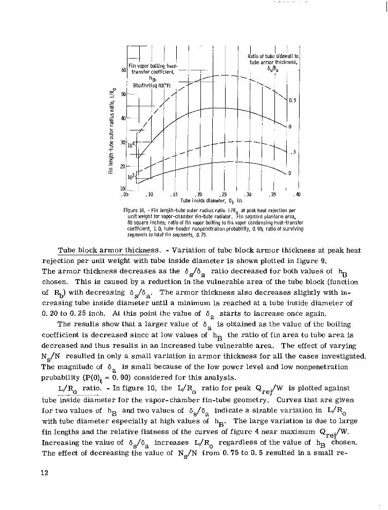
Figure 10. - Fin length-tube outer radius rat io L/Ro.at peak heat rejection per unit weight for vapor-chamber fin-tube radiator. Fin segment planform area, 80 square inches; ratio of f in vapor boiling to f i n vapor condensing heat-transfer coefficient, 1.9 tube-header nonpenetration probability, 0.99 rat io of surviving segments to total f in segments, 0.75.
Tube block armor thickness. - Variation of tube block armor thickness at peak heat rejection per unit weight with tube inside diameter is shown plotted in figure 9. The armor thickness decreases as the 6s/6, ratio decreased for both values of hB chosen. This is caused by a reduction in the vulnerable area of the tube block (function of Rb) with decreasing 6,/6.. The armor thickness also decreases slightly with in- creasing tube inside diameter until a minimum is reached at a tube inside diameter of 0. 20 to 0. 25 inch. At this point the value of 6, s tar ts to increase once again.
is obtained as the value of the boiling coefficient is decreased since at low values of hB the ratio of fin area to tube a rea is decreased and thus results in an increased tube vulnerable area. The effect of varying Ns/N resulted in only a small variation in armor thickness for all the cases investigated. The magnitude of 6, is small because of the low power level and low nonpenetration probability (P(0)t = 0. 90) considered for this analysis.
./W is plotted against
tube inside diameter for the vapor-chamber fin-tube geometry. fo r two values of hB and two values of 6,/6, indicate a sizable variation in L/Ro with tube diameter especially at high values of hB. The large variation is due to large fin lengths and the relative flatness of the curves of figure 4 near maximum Qrej/W. Increasing the value of 6,/6, increases L/Ro regardless of the value of hB chosen. The effect of decreasing the value of Ns/N from 0.75 to 0. 5 resulted in a small re-
The results show that a larger value of
L / R ~ ratio. - In figure 10, the L/Ro ratio for peak Q reJ
Curves that a r e given
12

/
/
Fin
R I I I I I Ratio of survivng segments
///;[ . 5
/'
M) 80 segment planform area, Asq
100 1M sq in.
Figure 11. - Variation of f in thickness with f in segment planform area at maximum heat rejection per unit weight for vapor-chamber fin-tube radiator. Capillary weight, 0.1 pound per square foot: hB = hC = lo4 Btu/(hr)(sq ft)("F); probability of NS or more segments not punctured, S, 0.90.
I l I l i I i Fin vapor boilins heat-
+- transfer coefficient.
t -z 03 04
. c
40 60 80 1W Fin segment planform area, ASw sq in.
Figure 12 -Variation of number of f in segments with f in segment planform area at maximum heat rejection per unit weight Capillary weight, 0.1 pounds per square foot; ratio of f in vapor boiling to f in vapor condensing heat-transfer coefficient, 1.0; tube-header nonpenetra- tion probability, 0.90; ratio of surviving segments to total f i n segments, 0.75; probability of NS or more seg- ments not punctured, 5, 0.90.
duction in L/Ro. The magnitudes of L/R, obtained at maximum heat rejection per unit weight were quite large compared to the results obtained for a high-temperature-level, high- power-level case presented in reference 9 where the values were approximately 2 to 4. Such high values of L/Ro are characteristic of low- temperature level radiators.
ness is governed primarily by meteoroid protec- tion considerations since heat transfer by con- duction along the fin is not considered in the anal- ysis (appendix C). The fin thickness at maximum Q ./W is plotted against fin segment planform area in figure 11 for two values of Ns/N. The increase in fin segment planform area, along with the necessary increase in the individual segment survival probability P(0)f for the same overall probability S , sharply increases the fin thickness. Increasing the value of Ns/N results in a larger fin thickness and thus in larger fin weight. Vari- ations in boiling and condensing heat-transfer co- efficients, tube block sidewall thickness ratio, and capillary weight resulted in a negligible change in fin wall thickness.
Fin thickness. - The vapor-chamber fin thick-
reJ
Number of fin segments. - The variation in the number of vapor-chamber fin segments with fin segment planform area is shown plotted in fig- ure 12 for two values of boiling heat-transfer co- efficient. The number of fin segments varies inversely with the fin segment planform area, Variations in tube diameter, in the ratio of the number of surviving segments to design segments, and in the tube block sidewall ratio, resulted in only small perturbations in the number of seg- ments. The number of fin segments is quite large (600 to 4000), regardless of the choice of fin seg- ment planform area considered. The large num- ber of fin segments poses the fabrication problem
13
I
II lllll1l1ll111111l1l Ill I 1 I1 I
,
20 40
T-I ii
Ratio of surv iv ing segments- to total f i n segments,
I
N S P
0.5 5
- 1 1
le I 1 diameter, I Di, in.
2- ~.
Fin segment planform area, ASq sq in.
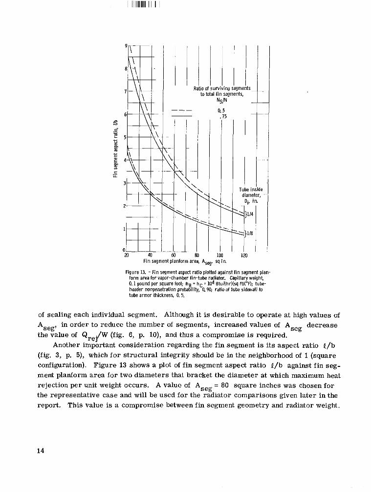
Figure 13. - Fin segment aspet.1 IdIlU pIuwu ayaii151 1 1 1 1 sty^ , form area for vapor-chamber f in-tube ragiator. Capillary weight, 0.1 pound per square foot hs. 5 hC = lo4 Btu/(hr)(sq ft)("F); tube- header nonpenetration probability, 0.90; rat io of tube sidavall to tube armor thickness, 0.5.
of sealing each individual segment. Although it is desirable to operate at high values of decrease
the value of Q Another important consideration regarding the fin segment is its aspect ratio l / b
(fig. 3, p. 5), which for structural integrity should be in the neighborhood of 1 (square configuration). Figure 13 shows a plot of fin segment aspect ratio B/b against fin seg- ment planform area for two diameters that bracket the diameter at which maximum heat rejection per unit weight occurs. A value of A = 80 square inches was chosen for the representative case and will be used for the radiator comparisons given later in the report. This value is a compromise between f i n segment geometry and radiator weight.
in order to reduce the number of segments, increased values of A Aseg7 seg
./W (fig. 6, p. lo), and thus a compromise is required. re3
seg
i I I 1
olan-
14

/ i
/ I
/ I ,
/
I
/
- .
Ri tube armor thickness,
0 _--
.a .25 .30 .35 .a I I I 1 . ~ 1 I Tube inside diameter, Di, in.
Figure 14. - Capillary f lu id boil ing heat f lux for vapor-chamber fin-tube radiator. F in segment planform area, 80 square inches; hB = hC = lo4 Btu/(hr)(sq ft)("F); ratio of surviv ing segments to total f in segments, 0.75.
Capi 1 lary Flow Requirements
The capillary fluid flow requirements for the vapor-chamber fin a re determined by the heat flux at the boiling surface and the latent heat of vaporization of the capillary fluid chosen. The boiling heat flux is given by the expression
4 &w - ' ueTf - A - (v)
The boiling heat flux obtained from the solutions of equation (l), which uses inputs ob- tained from the results of the radiator optimization, is plotted for peak Q ./W con- ditions in figure 14. The required heat flux is of the order of 5x10 Btu/(hr)(sq ft). The flux increases with increasing tube inside diameter for G S / 6 , = 0. 5 up to a diameter of 1/4 inch, at which diameter the heat flux decreases. The heat flux for 6$Ga = 0 continued to increase with increasing tube diameter. The reversal for the heat flux for b$Ga = 0.5 was brought about by a decreasing fin length at a diameter of 1/4 inch and larger. A decrease in heat flux with increasing sidewall thickness also occurred as shown in the figure. There was only a small variation in heat flux with Ns/N or with lower values of hB.
Some low-temperature tests to date using water as the capillary fluid in fiber-glass 3 4 wick material (ref. 10) yielded a heat flux range between 10 to 10 Btu/(hr)(sq ft). No
other information has been found that would indicate what is required to achieve the higher needed heat fluxes.
4 reJ
15

Ratio of tube sidewall to tube armor thickness, 24
.E
5- m - 16 m a 3 _ _ ~
c .d
c .- 12
m
m * m L
a.
4 8 z -
/= c
Lo Lo 1
4
d 0 .05
0 .5
I /e
/
/ / /5 oxide Diphenq mi
/ /
Wa
2 1 1 .a .25
Tube inside diameter, ..
Di, in.
-_
.35 .40
Figure 15. - Capillary f lu id flow rate for vapor-chamber fin-tube radiator. F in segment planform area, 80 square inches; hB = hC = lo4 Btu/(hr)(sq ft)("F); rat io of surviving segments to total f i n segments, 0.75.
The mass flow rate of the capillary fluid is determined by the expression (ref. 9)
4 . ~ E C J P T ~ m =
h
Results for equation (2) a r e plotted in figure 15 for peak Qrej/W for two choices of capillary fluid. A diphenyl-diphenyl oxide mixture and water were chosen to illustrate the effect of latent heat of vaporization on the mass flow rate per unit length of tube. Water, which has the higher latent heat, had the lower mass flow rate of the two fluids. The temperature dependent vapor pressures of the two fluids selected, corresponding to boiling and condensing heat-transfer coefficients of lo4 Btu/(hr)(sq f t ) ( O F ) , a r e approx- imately 2. 86 and 195 psia .for diphenyl-diphenyl oxide mixture and water, respectively.
Radiator Thermal Degradation
It was specified in the analysis of the vapor-chamber fin that 25 o r 50 percent of the individual fin segments could be punctured by meteoroids. Upon puncture the chamber
16

KFin chamber segments I \
/ \ ...- \ ---7- // -,--,,----- I \\
I I
Figure 16. - Vapor-chamber punctured fin segment arrangement
working fluid, which is under pressure, would be lost and the fin would no longer act as a vapor f i n ; however, the fin does not lose its radiating effectiveness entirely when punctured since it will then behave similarly to a solid-conducting double fin (fig. 2(b)). The degradation of the total heat rejection capabilities of the radiator with punctured fins then becomes a function of the number of surviving segments and the thermal effective- ness of the punctured fin segment.
surfaces of the punctured segment can also receive heat by conduction axially from the fin surface of adjacent unpunctured segments and by radiation from the bulkheads of the segment. Thus the true radiating effectiveness of a single punctured fin would be greater than indicated for the one-dimensional situation of figure 2(b).
In the absence of a more complete two-dimensional solution, an initial simplified approach was used that considers each punctured fin segment as a double fin tube and uses the one-dimensional analysis of reference 8 to obtain the new fin thermal efficiency. The characteristic fin length used in obtaining the fin efficiency is designated to be the minimum fin dimension in the plane of the radiator. The characteristic f i n length de- pends on the value of fin segment planform area, the segment aspect ratio Q/b, and the arrangement of the punctured segments, as shown in figure 16. For a single segment puncture, the characteristic fin length will be b or Q; for two segments punctured side by side laterally, the characteristic fin length will be b o r 28; and for two segments punctured side by side longitudinally, the characteristic fin length will be Q o r 2b.
radiator heat rejection after vapor fin puncture to the design heat rejection with no f i n puncture. The expression is
The actual physical case would require a two-dimensional analysis, since the fin
The reduction in radiating effectiveness can be measured in terms of the ratio of the
17

Q .(after puncture) reJ qD =
Q .(design) re1
(3)
The heat rejection after puncture is composed of the vapor header heat rejection QVH = (1 - Xtf)Qrej which is not affected, the heat rejection from the vapor chamber fins and tubes not punctured QrejXtf(Ns/N), and the heat rejection of the fins and tubes that are punctured and assumed to act as a double fin-tube geometry according to
Q = 2 ~ 8 q f + - 1 - - N ZT D ( :)( "".) (4)
where the double fin thermal efficiency qf is obtained by using the characteristic fin length associated with the punctured fin arrangement and the results of reference 8. It is assumed that the temperature of the adjacent hot chamber is maintained at the design value of Tf and, for simplicity of calculation, that the fin temperature is equal to the tube block sidewall temperature.
Figure 17 shows a plot of final one-dimensional thermal effectiveness ratio against fin segment planform a rea at peak Q two tube diameters chosen bracket the range at which maximum heat rejection per unit weight occurs and indicate the possible variation in radiator thermal effectiveness de- pending on the choice of tube diameter. Fo r the fin geometries involved in the calcula- tions, only the b, 8 , and 2b dimensions were required over the range of fin segment planform areas investigated.
In figure 17, for Di = 1/8 inch and Ns/N = 0. 5, the thermal effectiveness of the radiator follows the curve ABC as long as nonadjacent segments only a r e punctured. For segment areas up to 105 square inches (point B) the characteristic length is equal to b. Along the curve BC the characteristic length is 8 . Wnen two adjacent fins a re punc- tured laterally, the thermal effectiveness follows the curve AB for small fin segment areas, but continues on the curve BD for larger areas as b remains the characteristic length. If the radiator is made up of adjacent pairs of longitudinally punctured segments, the thermal effectiveness follows the curve E F along which 2b is the characteristic length. At point F, 2b equals 8 , and the thermal effectiveness follows the curve FC.
The curves for Ns/N = 0.75 (fig. 17(b)) follow the same pattern as those for Ns/N = 0.50 with the exception that the thermal effectiveness level is increased because of the larger fin thickness associated with the Ns/N = 0.75 case. The actual values of thermal effectiveness will occur between the single-puncture curve (A, B, C) and the double-puncture curve (E, F, C) depending on the frequency of single and double punctures.
./W for the typical design condition chosen. The reJ
18

Tube inside diameter,
Di, in.
1 I 4 --_
-
-
(a) Ratio of surviving segments to total f i n segments, 0.50.
Fin segment planform area, Asw sq in.
(b) Ratio of surviving segments to total f i n segments, 0.75.
tion. Capillary weight, 0. 1 pound per square foot; hg = hC = 104 Btul(hr)(sq ft)("F); tube-header nonpenetration probability, 0.90; probability of NS or more segments not punctured, 5, 0.90.
Figure 17. - One-dimensional vapor-chamber radiator thermal degrada-
COMPARISON OF RESULTS
The three fin-tube geometries, the vapor chamber fin-tube, and the solid- conducting central and double fin-tube radiators a r e compared in this section on the basis of weight, planform area, number of tubes, fin thickness, tube armor thickness, and panel aspect ratio. Because of the many variables involved in the vapor-chamber fin-tube radiator, a representative case was first selected for comparison with the other two geometries. Using the results presented in the previous section enabled the choice of A inches, which is based on a near square fin segment area, a boiling heat-transfer co- efficient of 10 Btu/(hr)(sq f t ) (OF), a vapor chamber capillary medium weight of 0. 10 pounds per square foot, and two values of Ns/N (0. 5 and 0.75).
= 80 square seg
4
19

11l11l11111l11111l1l111lllIIlIIII I111 Ill II I I I I
L
c m al L
(a) Double fin-tube radiator.
12 14 16 F in length-tube outer radius ratio, LIR,
(b) Central f in-tube radiator.
Figure 18. - Variations of heat rejection per unit weight wi th f i n length-tube outer radius rat io LIR probability, 0.90; tube inside diameyer, 0.125 inch.
Tube-header nonpenetration
Radiator Weight
Initially, the results of heat re- jection per unit weight for the two solid- conducting f in-tube geometries were plotted against the L/Ro ratio for fixed values of the conductance parameters Nc (ref. 2). The largest value of heat rejection per unit weight for each constant Nc curve was then plotted against L/Ro as shown for the sample case of figure 18. The corresponding case of a sample plot of heat rejection per unit weight against L/Ro is shown for the vapor- chamber fin-tube geometry in figure 4.
A comparison of the peak heat re- jection per unit weight results obtained from figures 4 and 18 along with re- sults for additional tube inside diam- eters a r e shown in figure 19 for the three fin-tube geometries for two values of tube nonpenetration proba- bility P(0)t. Both the central and double fin-tube geometries reach maxi-
mum Qrej/W at low diameters (0. 10 to 0. 15 in. ) with Q ./W decreasing substantially as Di increases. The tube block sidewall thickness ratio 6$6, has a small effect on the vapor fin radiator but a pronounced effect on the double fin radiator.
./W for the solid-conducting fin radiators, the vapor- chamber fin geometry is clearly not supe- r ior to the other geometries in Qrej/W. The vapor-chamber fin radiator, however, because of its small variation with diameter, becomes comparable to the double fin-tube radiator and somewhat better than the central fin-tube radiator at a diameter of 3/8 inch. At a value of P(0)t = 0. 995 (fig. 19(b)) the vapor chamber fin-tube radiator is consider- ably better than the central fin-tube radiator for all the diameters covered. Increases in Qrej/W of from around 80 to 130 percent are indicated at maximum Qre{W. For 6$6, = 0. 5, the vapor-chamber fin radiator is also substantially better than the double fin-tube radiator (order of 20 to 70 percent greater in maximum Q ./W). Only for 6,/6, = 0 is the vapor-chamber fin-tube radiator not superior to the double fin-tube
rel
For P(0)t = 0. 90 (fig. 19(a)), at tube diameters corresponding to peak Q reJ
re1
20

Doub
1
\
\
\ \
I '. -Vapor fin'*
$$ h t r a l f i n J
-H- - I I ill' Vapor f in4'
I I
Double
.I.\ i a t i i of surviving\ segments to total
f i n segments,
in
\ \
(a) Tube-header nonpenetration probability, 0.90.
F.Ao - sidewall to .
tube armor - thickness, .
%Pa .\ \
-
4 . 0 -
:o - .5 - __ . . - +- .5-
--0 - \-- .5 ---
-
Tube inside diameter, Di, in.
(b) Tube-header nonpenetration probability, 0.995.
Figure 19. - Comparison of peak heat rejection per unit weight. Fin segment planform area, 80 square inches; h B = h C = lo4 Btul(hr)(sq ft)("F).
21
I

lIIIlIll1111l1l111l11111 I II I1 I
0 I
\
\ \ \
I ,
Ratio of tube s idew al I to tube armor thickness,
c (a) Vapor fin. '6 .35 E (31
3
.25
. 0 5 . 1 0 .15 .XI . 2 5 .M . 3 5 .40 Tube inside diameter, Di, in.
(b) Central and double fin.
Figure 20. - Comparison of ratio of f i n weight to total radiator weight at peak heat rejection per unit weight. Fin segment planform area, 80 square inches; hB = hC = 18 Btu/(hr)(sq ft)('F); tube-header nonpenetration probability, 0.90; ratio of surviv ing segments to total f i n segments, 0.50 and 0.75.
radiator at P(0)t = 0. 995. The results of figure 19 are due to large differences in the proportion of the total
weight involved in the fins of the solid-conducting and vapor-chamber fin-tube geome- tries as indicated in figure 20. The vapor-chamber fin-tube radiator has a large fin thickness, long fins, and thus more weight, whereas the double fin-tube geometry has small fin thickness, shorter fin length and thus less fin weight. This is brought about because the fin thickness for the vapor-chamber fin is determined by meteoroid puncture considerations as discussed in the CHARACTERISTICS section, and the double fin by heat- transfer optimization.
mum heat rejection per unit weight for the three fin-tube configurations is shown in The effect of varying the tube and header nonpenetration probability P(0) on maxi- t
22

.- E 3
Tube nonpenetration probability, P(O)t
Figure 21. - Comparison of maximum heat reject ion per unit weight plotted against radiator tube nonpenetration probability. Fin segment planform area, 80 square inches. capillary weight, 0.1 pound per square foot; hB = hC = 104 Btu/(hr)(sq ft)("F); ratio of tube sidewall to tube armor thickness, 0.5; probability of NS or more segments not punctured, S, 0.90.
figure 21 for 6,/6,. = 0.5. There is a sharp decrease in maximum Q the two solid- conducting fin-tube geome- tries as P(0)t increases but only a slight decline for the vapor-chamber f i n radiator. Once again this is primarily due to the large proportion of the weight contained in the fins for the vapor- chamber fin-tube radiator. The relative weight comparison improves in favor of the vapor fin-tube radiator as the tube and header nonpenetration probability P(0)t is increased. For Ns/N = 0.5, the vapor fin becomes better than the double f i n at P(0)t greater than 0.95. At Ns/N = 0.75 the double fin is always better than the vapor fin radiator. Thus, a more com- plete comparison between the geometries depends on a compromise between the
./W for re1
weight and thermal degradation of the vapor- chamber fin radiator.
Radiator Geometry
Planform area. - Comparison of the planform area results of the three fin-tube ~-
geometries is shown plotted in figure 22. A sizable decrease in radiator planform area is afforded by the vapor-chamber fin-tube geometry compared with the other two fin- tube configurations over the entire range of tube inside diameters investigated. For the 30-kilowatt power level investigated, the vapor-chamber fin-tube geometry gives re- ductions in planform area of from 22 to 40 percent over the central fin-tube geometry for the full diameter range investigated. A t the minimum weight condition, the planform area reduction is about 30 percent as shown in the figure. The vapor fin affords an ap- proximately similar reduction in planform area compared to the double fin-tube geo- metry. Variations in 6$6, and Ns/N had little effect on radiator planform area.
The planform area of the vapor-chamber fin-tube geometry has a relatively flat variation with tube inside diameter and thus allows a wide choice of tube diameters (and correspondingly, of number of tubes) without compromising planform area or re- ducing radiator heat rejection per unit weight (fig. 19). The planform area of the
23

900
850.
800
- L
U VI
b 750 4
m- a, L m
E 0 c m cz L 0
U m w
L
-
.- 650
w-
/ 700--7-
/
laximum Qrej
Maximum Qre,/W- I I 1 1 ' 1 A-
500 .05 MI .10 . 15 .m I .25 I
i
* -
-
lor
t .30 1
Tube inside diameter, Di, in.
Figure 22. - Comparison of planform area at peak heat rejection per unit weight F in segment planform area, 80 square inches; hB = hC = 104 Btul(hr)(sq ft)("F); tube-header nonpenetration probability, 0.90; ratio of surviv ing segments to total f i n segments, 0.75; ratio of tube sidewall to tube armor thickness, 0.5.
central fin and double fin geometries showed a substantial variation with tube inside diameter.
A concise way of showing the heat rejection per unit weight and radiator planform area comparisons at peak Q directly plotting Q for P(0)t = 0. 90.
./W for the three fin-tube geometries can be obtained by ./W (from fig. 19(a)) and A (from fig. 22), as shown in figure 23
Number of tubes. - The number of radiator tubes for the three geometries at peak
re.l re1 P
Q shown in figure 24. In general, the vapor-chamber fin-tube geometry had the smallest number of tubes for any specific choice of tube inside diameter. ber of tubes for the three radiators at the diameter corresponding to maximum heat re- jection per unit weight (see fig. 19) indicated that the vapor-chamber fin-tube radiator at 6,/6, = 0. 5 required 13 tubes at a diameter of 1/4 inch, whereas the central fin-tube radiator had approximately 57 tubes at a diameter of 0. 15 inch and the double fin-tube radiator had 85 tubes for 6 /ija = 0. 5 and a diameter of 0.125 inch. This trend also held for 6,/6, = 0. An additional advantage of the vapor-chamber fin-tube radiator is
./W was found to decrease substantially as the tube inside diameter increased, as re1
Comparison of the num-
S
24

I
160
b- z
vi W .a 3
0
120
c
z
0 i .05
!atio I l l of surviv ing
segments to total i in segments,
NSlN
0.5
f i n
- .
I Radiator
/
/
J 820 900 i form area, Ap sq f t
Figure 23. - Maximum heat rejection per unit weight plotted against radiator planform area. Fin segment planform area, 80 square inches; hB = h C = 104 Btu/(hr)(sq ft)("F); tube-header nonpenetration proba- bility, 0.90; ratio of tube sidewall to tube armor thick- ness, 0.5.
Tube inside diameter, Di, in.
h
?--
Figure 24. - Comparison of number of radiator tubes at peak heat rejection per unit weight at each diameter. F in segment planform area, 80 square inches; hB = hC = lo4 Btu/(hr)(sq ft)("F); tube-header nonpenetration probability, 0.90; ratio of surviv ing segments to total f i n segments, 0.75; ratio of tube sidewall to tube armor thickness, 0.5.
25
Ratio of surviving segments to total
.05
I I Ratio of tube sidewall to tube armor thickness, .
'$a .
0.75 I I I I I I Vapor f i n
. ~.
Tube inside diameter, Di, in.
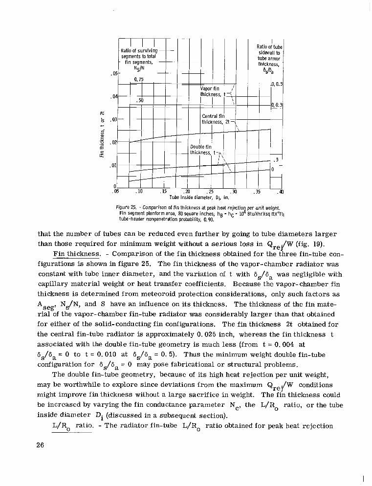
Figure 25. - Comparison of f i n thickness at peak heat rejectio per unit weight. Fin segment planform area, 80 square inches; hB = hC = K! Btu/(hr)(sq ft)("F); tube-header nonpenetration probability, 0.90.
that the number of tubes can be reduced even further by going to tube diameters larger than those required for minimum weight without a serious loss in Qrej/W (fig. 19).
Fin thickness. - Comparison of the fin thickness obtained for the three fin-tube con- figurations is shown in figure 25. The fin thickness of the vapor-chamber radiator was constant with tube inner diameter, and the variation of t with 6,/6, was negligible with capillary material weight or heat transfer coefficients. Because the vapor- chamber fin thickness is determined from meteoroid protection considerations, only such factors as
Ns/N, and S have an influence on its thickness. The thickness of the fin mate- rial of the vapor- chamber fin-tube radiator was considerably larger than that obtained for either of the solid-conducting fin configurations. The fin thickness 2t obtained for the central fin-tube radiator is approximately 0.025 inch, whereas the fin thickness t associated with the double fin-tube geometry is much less (from t = 0.004 at 6,/6, = 0 to t = 0,010 at 6,/6, = 0. 5). Thus the minimum weight double fin-tube configuration for 6,/6, = 0 may pose fabricational or structural problems.
may be worthwhile to explore since deviations from the maximum Qrej/W conditions might improve fin thickness without a large sacrifice in weight. The fin thickness could be increased by varying the fin conductance parameter Nc, the L/Ro ratio, o r the tube inside diameter Di (discussed in a subsequent section).
Aseg'
The double fin-tube geometry, because of its high heat rejection per unit weight,
L/Ro ratio. - The radiator fin-tube L/Ro ratio obtained for peak heat rejection
26

.10
\\
- \
/
K-Vapor f i n / I . <L \ -
- .10 .15 .#
Tube inside diameter, Di, in.
Figure 26. - Comparison of radiator f i n length-tube outer radius rat io L/Ro at peak heat rejection pe unit weight. Fin segment planform area, 80 square inches; h B = hC = lodBtu,(hr)(sq WW; rat io of surv iv ing segments to total f i n segments, 0.75.
. 221
.a
.+ . 18 r?r
vi 0
v) a? .16 .-
5 L 0 E L
.14 3 I-
.12
.10 .OS
Tube inside diameter, Di, in.
Figure 27. - Comparison of tube armor thickness at peak heat rejection per u n i t weight. F in segment planform area, 80 square inches; hB = hC = lo4 Btu/(hr)(sq ft)("F); tube-header nonpenetration probability, 0.90; rat io of sur- viving segments to total f i n segments, 0.75.
27
I

per unit weight at each diameter for the vapor-chamber, double, and central fin-tube geometries is shown plotted in figure 26. The L/Ro associated with the vapor chamber fin-tube geometry is much larger than that for the other two geometries (from 45 at 6,/6, = 0 to 58 at 6,/6, = 0.5) and peaks at a diameter of about 1/4 inch. The L/Ro ratio is seen to increase slightly for the double fin-tube geometries as the 686 , ratio increases. Values of actual fin length Q for the vapor-chamber and double fin-tube radiators can be obtained from the value of L/Ro (fig. 26), the tube armor thickness (fig. 27), the ratio 6s/6a, and equation (B6).
tube inside diameter for the three geometries investigated. fin radiators have less armor thickness than the central fin radiator since their vulnerable area is based on the projected area of the tube block rather than on the full outer surface of the tube, a s in the case of the central fin radiator. Furthermore, the vulnerable area of the vapor fin is further reduced because of the smaller planform area resulting from the higher thermal effectiveness. The armor thickness for both the double and vapor- chamber fin-tube geometries decreases with decreasing 6 s/6 a since the vulnerable area of the tube block decreases a s the sidewall protection thickness 6, decreases.
three fin-tube geometries in figure 28 for the peak heat rejection per unit weight con- dition. A pronounced decrease in aspect ratio occurs with increasing tube diameter. In general, the vapor-chamber fin-tube geometry results in the largest aspect ratio. Al l three radiator configurations have aspect ratios less than 1. 5 at tube diameters of practical interest (diameters greater than 1/8 in. ). For the vapor fin and double fin radiators the effect of decreasing 6,/6, from 0. 5 to 0 resulted in a small decrease in aspect ratio. There was no appreciable change in w/Z with the value of Ns/N for the vapor-chamber fin-tube radiator.
Tube armor thickness. - ._ - - - Figure 27 shows a plot of tube armor thickness 6, against Both the double and vapor
Panel aspect ratio. - Radiator panel aspect ratio w/Z is shown plotted for the
Thermal Character ist ics
Another interesting aspect that can be compared for the fin-tube geometries under investigation is the thermal characteristics of the fin for optimum radiator weight. Fig- ure 29 shows a plot of the conductance parameter Nc at peak heat rejection per unit weight against tube inside diameter for the two solid-conducting fin-tube geometries. The conductance parameter for both the double and central fin-tube geometries in- creases with increasing tube inside diameter. This trend was also found to hold for the high-power-level investigation of reference 8. A t the tube diameters that yielded mini- mum weight for the central and double fin configurations (0.125 in. < Di < 0. 150 in. ), the conductance parameter for both geometries was in the range 0. 55 to 0.65 for the illustrative case presented.
28

I i
-Central
3. 5
3.0 . 3 0-
e - 2. 5 a
._ c
u m
v) m
a c -
x 2.0 L 0 m v m E
c .-
1. 5
1. 0
1
f i n
ir f
. === ~
Tube inside diameter, Di, in.
Figure 28. - Comparison of radiator panel aspect ratio at peak heat rejection per u n i t weight. F i n segment planform area, 80 square inches; hB = hC = 104 Btul lhrNsq ft)(”F); tube-header nonpenetration probability, 0.90; rat io of sur viving segments to total f i n segments, 0. 75; ratio of tube sidewall to tube armor. thickness, 0.5.
In many instances it is desirable to operate at fin-tube L/Ro ratios off the optimum value in order to compromise other radiator design conditions such as planform area o r fin thickness. This can be accomplished for the two solid-conducting fin geometries by varying one or more of the following parameters: tube diameter, L/Ro, or conductance parameter. If for example, the tube diameter is assumed fixed at the value that yields minimum weight, the L/Ro ratio and Nc can be varied within a set allowable decrease in heat rejection per unit weight. A sample set of curves showing the zones of L/Ro and conductance parameters for near minimum weight is given in figure 30 for the central and double fin-tube radiators. The lowest Nc point on a curve corresponds to the minimum planform area of the radiator, whereas the maximum N yields the maximum planform area.
tries, the fin should be designed to have a smaller value of conductance parameter Nc.
point on a curve C
In order to increase fin thickness for either the central or double fin-tube geome-
29

1. 8 r c 1. 6 , L
I 1 . 4 L
V I c = 1 . 2 1 - c d l E L m
Figure 29. - Conductance parameter at peak heat rejection per un i t weight T u b e header nonpenetration probability, 0.90; rat io of tube sidewall to tube armor thickness, 0.5.
I l l Zone of maximum heat reiection Qrej/W minus 5 percent -\
ooi nt
II Zone l l ! L of maximum
heat rejection Q r e P minus
. 1 - 5percent, IA / I /
I 8 10
/ '-Mi nir
Fin length-tube outer radius ratio, LIR,
(a) Central fin-tube; tube inside diameter, 0.15 inch. (b) Double fin-tube; rat io of tube sidewall to tube armor thickness, 0.5; tube inside diameter, 0.125 inch.
Figure 30. - Zones of f i n length-tube outer radius rat io LIR, and f i n conductance parameters for near min imum weights, Tube-header nonpenetration probability, 0.90.
30
I

I-" 1 c .-
E
a- c
L
c m L W a.
=l
E c a In rrr
c n
s .- - c g .- E - 0 0
m E
.- c
+Vapor f i n
.25 .30 i .40
Tube inside diameter, Di, in.
Figure 31. - Comparison of rat io of midfin to f in base temperature at peak heat rejection per un i t weight. hB = hC = 104 Btu/(hr)(sq ft)("F); tube-header non- penetration probability, 0.90; rat io of surviving segments to total f i n segments, 0.75; ratio of tube sidewall to tube armor thickness, 0.5.
Thus, for example, by reducing the conductance parameter Nc from 0. 55 to 0.22 the fin thickness of a double fin-tube radiator can be increased from 0.008 to 0. 015 inch with only a 5-percent penalty in heat rejection per unit weight (conditions of fig. 3O(b)).
the resultant thermal s t resses on a fin due to the inherent temperature drops in the solid conducting fin geometries. Typical results showing the ratio of mid-fin to fin-base tem- perature a r e shown plotted against tube inside diameter for the three fin-tube geome- tries in figure 31. The vapor fin exhibits a near isothermal gradient because of the internal mode of heat transfer and thus should pose no thermal s t ress problems during operation. If a vapor fin segment is punctured, a temperature drop less severe than that of the double fin would result, because the fin thickness is large compared to that of the double fin. Accordingly, the resultant thermal s t ress will be less than that exhibited by the double fin.
The thermal characteristics of the fin take on added importance when considering
Comparison w i t h High-Power-Level Results
The results and comparisons of the three fin-tube geometries obtained for this low- temperature-level, low-power-level study are a followup of a previous effort (ref. 9) which analyzed two high-power-level, high- temperature-level space radiator systems for a P(0)t = 0.995 and Ns/N = 0.75. The results of reference 9 were for a columbium radiator for a 500-kilowatt power cycle and a beryllium radiator for a 1-megawatt power cycle, both of which had a radiator fluid inlet temperature of 1700° R. The comparisons
31

of the three fin-tube geometries for the high- and low-power-level cases will be made on the same basis: that is, at peak heat rejection per unit weight, at the same values of tube block sidewall ratio, vapor fin overall nonpenetration probability, tube and header nonpenetration probability, ratio of surviving to design fin segments, and fo r fin seg- ment planform areas resulting in nearly square segments.
Radiator weight. - For the high-power-level radiators at 6,/6, = 0. 5, the vapor fin radiator with f i n segment planform area equal to 20 square inches had a Q 50 to 68 percent greater than that for the double fin geometry, and from 60 to 87 percent greater than that for the central fin geometry. The low-temperature aluminum radiator for the 30-kilowatt power cycle at Gs/Ga = 0. 5 and A = 80 square inches indicated a reduced advantage (18 percent) for the vapor fin over the double fin geometry, and an advantage somewhat less than that for the high power level cases over the central fin- tube geometry (80 percent). Decreasing the tube block sidewall ratio from 0. 5 to 0 gave the vapor fin geometry a decreased advantage in Qrej/W over the double fin radiator of f rom 44 to 58 percent for the high power level cases but resulted in a sizable reduction in the value of Qrej/W below that for the double fin geometry for the 30-kilowatt-power- level aluminum radiator.
The reduction in the Qrej/W advantage of the vapor-chamber fin over the solid- conducting double and central fin geometries (Gs/ t ja = 0. 5) at the low power level is a result of the relative proportions of the total weight involved in the fins and in the tubes. At the low power level, the vapor chamber fins comprise 29 percent of the radiator weight, whereas at the two high power levels the fin weight is reduced to 13 to 15 percent of the total weight at a tjS/Ga = 0. 5. Thus a reduction in the tube armor sidewall thick- ness will have a greater effect on the percent weight reduction for the high-power-level cases. The large fin weight for the low-power-level vapor-chamber case is brought about because of the large required planform area (similar in magnitude to the high- power-level radiators) in conjunction with the meteoroid puncture protection requirement of each individual fin chamber.
cause of the high thermal conductivity of aluminum which allows long thin fins of rela- tively small weight. The lower thermal conductivity associated with the high-power- level beryllium and columbium radiators required relatively thicker fins and thus more weight for the solid-conducting fin geometries, which in turn gave an advantage to the vapor fin when compared on a weight basis.
radiator comparisons a r e geometric aspects such as radiator planform area which for the three fin-tube configurations investigated yields minimum area for the vapor- chamber fin-tube geometry for both power levels. In the low-temperature level case (fig. 22), a 20 to 40 percent decrease in planform area was obtained for the vapor-chamber fin-tube
./W from reJ
seg
The double fin geometry is attractive on a weight basis for the 30-kilowatt case be-
Radiator geometry. - Other factors of interest in the high- and low-power-level
32

geometry compared to either the central or double fin-tube configurations. temperature level, high-power-level case of reference 9, the planform area advantage of the vapor-chamber fin is reduced to between 18 to 32 percent for the columbium radi- ator and to between 12 and 21 percent for the beryllium radiator.
Comparison of the fin-tube configuration of the high- and low-temperature level solid- conducting f i n cases indicated the low-temperature radiator resulted in values of L/Ro from three to five times larger than those characteristic of the high-temperature case. For the vapor-chamber fin-tube radiator, the value of L/Ro at low temperature was 8 to 12 times greater than the value at the high-temperature level. This large dif- ference was brought about in part by the small tube inside diameters and armor pro- tection thickness characteristic of low-temperature level, low-power-level systems and the large fin lengths required. Thin fins are another characteristic of the low- temperature solid- conducting double f in-tube configuration that may require an off optimum weight design in order to increase the thickness. At high-temperature level, the fin thickness is considerably larger and should not pose structural problems.
bulkheads for the vapor-chamber f i n s in order to improve the structural capability of the fin. The high-temperature, high-power case did not require the longitudinal bulkhead because of the relatively short fin lengths.
num, the reduction in thermal effectiveness upon puncture of 25 percent of the fin seg- ments is 4 to 6 percent less than that exhibited by the beryllium and columbium radia- tors, respectively. The relatively lower thermal degradation of the aluminum radiator can also allow operation at lower values of Ns/N, which tends to decrease the weight of the aluminum vapor fin radiator.
For the high-
The large fin lengths at the low power level also indicated the need for longitudinal
Thermal degradation. - Because of the high value of thermal conductivity for alumi-
SUMMARY OF RESULTS
The analysis of the vapor-chamber fin-tube configuration for the 30-kilowatt low-
1. The vapor-chamber fin-tube geometry at maximum heat rejection per unit weight temperature Rankine steam cycle yielded the following results:
is characterized by long fins (approx. 10 to 16 in. ), tube inside diameters from 0. 15 to 0.25 inch, and relatively few short tubes. Ratios of fin length to tube radius were on the order of 40 to 60.
and planform areas of the order of 500 to 600 square feet were achievable for the vapor- chamber fin radiator for a zero degree sink temperature.
2. Values of heat rejection per unit weight of the order of 600 to 1400 Btu/(hr)(lb)
3 . Relatively small variations with tube inside diameter were obtained for radiator
33

heat rejection per unit weight and radiator geometry (planform area, etc. ) for the range of diameters from 0.075 to 0.375 inch at peak Q
fin-tube geometry, increasing the fin segment planform area (to reduce the number of fin segments) o r the weight of the f i n chamber capillary medium resulted in substantial reductions in heat rejection per unit weight.
5. Required capillary boiling heat fluxes were on the order of 5x10 Btu/(hr)(sq ft), while capillary fluid flow rates of 6 to 25 pounds per hour per foot of tube length were indicated for a diphenyl-diphenyl oxide mixture and approximately 1 to 4 pounds per hour per foot required for water.
probability that 50 percent of the vapor-chamber fin segments would be punctured, while a maximum 10 percent degradation was indicated for a 75 percent survival.
7. Variation of the tube block sidewall thickness ratio had only a small effect on radiator weight and geometry for the vapor- chamber fin-tube.
A comparison of the vapor fin-tube geometry with the central and double fin-tube geometries indicated the following:
1. For a tube nonpuncture probability of 0.90, the vapor-chamber fin radiator was clearly not superior in heat rejection per unit weight to the central and double f i n geome- tr ies. Largest values of heat rejection per unit weight were for the double-fin geometry radiator.
2. For a tube nonpuncture probability of 0.995, the vapor-chamber fin radiator had a substantially greater maximum heat rejection per unit weight compared to the central fin-tuberadiator (80 to 130 percent increase) over the entire range of tube inner diam- eters from 0.075 to 0.375 inch. For 6,/6, = 0. 5, the vapor-chamber fin radiator was also substantially better than the double-fin radiator (order of 20 to 70 percent greater in maximum Qre./W). It was only for the case of 6$6. = 0 that the vapor-chamber fin radiator was not superior to the double fin radiator.
3. Radiator heat rejection per unit weight decreased substantially with increasing tube nonpenetration probability (from 0. 90 to 0.995) for the central and double fin-tube geometries, whereas the vapor- chamber fin-tube geometry (with constant fin chamber nonpenetration probability) showed only a slight decrease.
4. The central and double fin-tube radiators reached peak heat rejection per unit weight at low tube inside diameters (0. 10 to 0. 15 in. ) with the heat rejection per unit weight dropping off sharply with increasing tube inside diameter. The vapor-chamber fin-tube radiator reached its peak at larger diameters (0. 15 to 0.25 in. ) and exhibited relatively little variation with tube diameter.
chamber fin-tube geometry over the central or double fin-tube radiators for peak
./W conditions. re1
4. Because of the large amount of weight contained in the fins for the vapor-chamber
4
6. A maximum thermal degradation of 20 percent was indicated for a 0.90 overall
5. A 20 to 40 percent reduction in radiator planform area is attained with the vapor-
34

Qrej/W conditions over the range of tube inner diameters considered.
four times greater than those of the central or double fin-tube radiators.
could be obtained with only small weight penalties. considerable latitude in fin thickness was also available for a small weight penalty.
6. In general, the vapor-chamber fin-tube radiator resulted in fin lengths two to
7. For all three radiator configurations considerable variation in panel aspect ratio For the two conducting fin geometries
Lewis Research Center, National Aeronautics and Space Administration,
Cleveland, Ohio, July 15, 1965.
35
I

II ! I ll!!1l!!!1l1!1111l1l!llllll!l~l!llll1111,,l, I I I I I1 I , . . . . . _.. . .
APPENDIX A
A
AP
Aseg
b
D
Di
DO
Ea
h
hB
hC ..
J
KH
k
L
surface area, sq f t
radiator planform area, sq f t
SYMBOLS
L*
fin segment planform area, sq f t
vulnerable area for meteoroid protection, sq f t
fin segment width, f t
diameter, f t
tube inside diameter, f t
tube outside diameter, f t
Young's modulus of target material, lb/sq f t
view factor
conversion factor, f t lbm/lbf sec2
heat of condensation, Btu/lb
fin vapor boiling heat-transf er coefficient, Btu/( hr) (sq f t ) ( O F )
fin vapor condensing heat- transfer coefficient, Btu/(hr)(sq f t ) ( O F )
mechanical equivalent of heat, 77 8(ft)(lbf)/Btu
header to tubes = 1 .15 fluid pressure loss factor from
thermal conductivity , Btu/(f t) (hr) ( O F )
Minimum half length of fin * between tubes, (L - Ro), f t
Q
ni
N
NC
NS
$b
QD
Qf
Qrej
QVH
one half tube center to center distance, f t
half length of fin between tubes,
L + (1 -?>Ga, f t
mass flow rate, lb/(hr)(ft)
number of fin segments
fin conductance parameter, 3 2 UTb 1
kt
number of fin segments not punctured in given time T
number of radiator tubes
cycle fluid pressure, psf
probability of no critical damage to radiator tube, headers, or fin segments
tube radiant heat rejection rate, Btu/hr
heat rejection rate from punc- tured vapor fins and tubes, Btu/hr
for a half fin length Q radia- ting from both sides, Btu/(hr)
rate, Btu/hr
rate, Btu/hr
fin radiant heat rejection rate
total radiator heat rejection
vapor header heat rejection
36

heat rejection rate per unit tube length, Btu/(hr)(ft)
tube sidewall to tube center- line dimension,
Ri
RO
S
TS
Tb
Tf
Tw
T*
t
tube inside radius, f t
tube outside radius, f t
probability of Ns or more segments not punctured in time r
average vapor temperature in fin chamber, OR
outer surface, OR
surface, OR
temperature of tube block
average temperature of fin
temperature of tube block 0 sidewall, R
static fluid temperature at 0 tube inlet, R
thickness of fin (double and vapor fin), half thickness of central fin, f t
U velocity of vapor, ft/sec
V velocity of liquid, ft/sec
W weight, lb
W mass flow per tube, lb/sec
W panel width, f t
fractior, of total heat re- jected by the vapor header
*VH
xtf
Z
6a
6B
6f
6S
E
rl
VD
rl*
e I-1
P
pw6w (T
x
r
fraction of total heat rejected by the tubes and fins
tube length, f t
tube armor protection thickness, f t
fin longitudinal bulkhead thick- ness, f t
tube liner thickness, f t
fin transverse bulkhead thick- ness, f t
tube sidewall thickness, f t
surface hemispherical emis- sivity
efficiency
degraded radiator effectiveness
effectiveness
temperature ratio, T / T ~
viscosity of working fluid, lb/( f t) (s e c)
density, lb/cu f t
capillary weight, lb/sq f t
Stefan- Bolt zmann constant, 1 . 7 1 3 ~ 1 0 - ~ Btu/(sq ft)(hr) (OR4)
vapor- chamber fin heat- transfer parameter
mission time, days
Subscripts
a tube armor
b tube base surface
C tube liner
37

f fin
LH liquid header
m momentum
min minimum
0 outside
P particle
R total
t tube
VH vapor header
W tube block sidewall
0 conditions at tube inlet
3 radiator inlet conditions
38

APPENDIX B
HE AT-TR AN S FER ANA LY S I S
General Considerations
The heat rejection analysis involved considers the thermal characteristics of the central, double, and vapor fin-tube radiator configurations shown in figure 2. The governing equations that yield the fin temperature profiles for the three fin-tube configu- rations are developed in references 2, 8, and 9. Solution of these descriptive equations a re then used to determine heat rejection characteristics, such as individual fin and tube thermal efficiency and total fin-tube thermal effectiveness. Basic equations describing thd total fin-tube effectiveness for the central and double fin-tube geometries were de- rived by using blackbody considerations, whereas the vapor- chamber f in-tube geometry included the effect of emissivity. The blackbody heat rejection for the central f i n was then multiplied by an apparent emissivity of the cavity formed by the tubes and fin (ref. 4). The blackbody heat rejection of the double fin-tube was multiplied by the sur- face emissivity because of the nature of the geometry.
input to the fin is composed of heat conduction along the fin from the fin base and inci- dent radiation from the two base surfaces. In the case of the double fin tube configura- tion, additional incident radiation comes from the opposing fin surface. For the vapor fin-tube geometry the modes of heat flow in the fin consist of boiling a capillary fluid on the tube block sidewall and condensing it on the internal f in surface. The condensate on the fin surfaces is returned to the block surface by capillary pumping. Inasmuch as the fin and tube block temperature will not be very different, there will be only negligible additional heat input to the fin by conduction from the base and by radiation from the block surface. fin-tube panel to a surrounding environment of 0' R assumed for this comparison.
transfer relation for all the geometries considered:
In the analysis, it is assumed for the central fin and double fin geometries that energy
Radiant emission for the three geometries comes from both sides of the
Several specific assumptions a re used in the development of the fin-tube heat-
(1) Incident radiation from external sources is negligible. (2) The effect of surface emissivities less than 1 on fin-tube thermal effectiveness
(3) Steady-state one-dimensional heat flow occurs in the tube wall. (4) The development of the f i n and tube angle factors is based on an infinite longitudi-
(5) The inside tube wall temperature is uniform circumferentially and equal to the
is small and thus neglected.
nal extent of fin and tube and zero fin thickness.
static temperature of the fluid evaluated at the inlet conditions of the tube.
39

(6) Material properties such as thermal conductivity, modulus of elasticity, and
Additional assumptions required for the vapor- chamber fin-tube configuration a r e (1) Steady-state heat transport within the vapor chamber with uniform vapor satura-
(2) The transverse and longitudinal bulkheads are adiabatic surfaces. (3) The temperature of the f i n surface and each tube block surface is uniform. (4) Tube block outer wall and sidewall temperatures are equal (appendix C).
emittance are constant and based on the tube inlet inside wall temperature.
tion temperature along the length of the f i n .
Central Fin-Tube (fig. 2(a))
The analysis of reference 13 was used to determine the fin temperature profile that in turn enabled the determination of the net heat rejected from the fin. The net heat loss Qf from both sides of a fin of length L when compared to the ideal amount of energy that can be rejected from a black isothermal surface yields the following dimen- sionless expression for the thermal efficiency of the fin
Qf
where (dO/dX)X,O is obtained from solutions for the fin temperature profile (ref. 13). The base surface efficiency qb is defined as the net heat loss from one-quarter of
a tube outer surface Qb divided by the maximum emission possible ( E = 1.0) from the one-quarter periphery of the tube. The expression is
The integral in equation (B2) also makes use of the fin temperature profile (ref. 13). The total thermal effectiveness of the fin and tube can then be obtained from the
expression
40

1.0
h I \ \
\
\
\
\
Fin conductance parameter,
NC
6 8 10 Fin length-tube outer radius ratio, L/Ro
Figure 32. -Total f in-tube effectiveness plotted against f in length-tube outer radius ratio LIR, for central fin-tube radiator.
* V f VR= --
RO 1 + -
ir Ro -- qb 2 L + - l + -
L L
The values of overall thermal effective- * ness q R obtained from equation (B3) a r e plotted against the fin profile ratio L/Ro for selected values of the conductance parameter N in figure 32.
(T* - Tb) is determined from one- dimensional conduction based on a heat flow from the inner to the outer wall which is rejected by radiation and is given by the ex- pression (ref. 4)
C The temperature drop in the tube wall
w(Di + 26c + 26,) Tb l$i + 26c + 2 6 z j 2 Di+ 2.6,
- k(T* - Tb) = 0 (B4)
Double Fin-Tube
The double fin-tube configuration shown in figure 2(b) used the analysis of refer- ence 7 to obtain equations describing the radiant heat-transfer characteristics.
For this geometry the fin thermal effectiveness can be defined as the amount of energy rejected from the fin divided by the maximum that can be rejected from both sides of an isothermal black fin-tube geometry of length 2(Q + %). This expression is
Qf 2- Z 1 J6’ e4 dx
41
I

The temperature profile 8 (obtained from ref. 7) in equation (B5) is a function of position X on the fin for specific values of 6,/6., L/Ro, and Nc. The ratio Rdp in equation (B5) is defined in te rms of 6,/6., which is the fraction of the armor thickness retained on the enclosed side of the tube block.
The blackbody base-surface effectiveness can be calculated by the equation
'b
* The total blackbody thermal effectiveness qR is then obtained by adding the results of equations (B5) and (B7):
Solutions of equation (B8) are shown plotted in figure 33 against L/Ro for specific values of the conductance parameter Nc and 6,/6,. The curves of figure 33 do not equal 1 at L/Ro equal to zero for 6 s/6 a values other than 1 since a fin of length 6 remains.
The temperature drop through the tube block (fig. 2(b)) is determined by using a
The simplified approach which assumes that the heat radiated from the exposed surface of the tube block is transferred from the tube inner surface across the length 6,.
temperature drop equation is
42

W c a, >
p c t . 6
z c c .- c - m .5 + 0 +
. 4
. 3
. 2 0
\ \
\ '\
\ \
\ \
.. 2 6 j_
I t Ratio of .Jbe F
1 1
armor thickness, parameter, 6 S P
Fin length-tube outer radius ratio, L/Ro
Figure 33. -Total f in-tube effectiveness plotted against f i n length-tube outer radius ratio LIR, for double fin-tube radiator.
Vapor -Chamber Fin -Tu be
Equations describing the internal heat-transfer mechanisms of the vapor- chamber fin along with an evaluation of the fin performance a r e given in appendix C. Using the results given in appendix C for the fin temperature profile (see eqs. (C4) and (C5)) en- ables the determination of the total fin-tube thermal effectiveness that can be obtained by comparing the tube block and fin net heat rejection with the maximum that can be re- jected from a fin-tube of length 2(Q + %):
43

laOF .95
ft nr
.- L
c 0
.75
.70 10-3 10-2
\
% \ $
IRb
1
5
10
m-
__
W-
10-1 F in heat-transfer parameter, A
Figure 34. - Total f in-tube effectiveness for vapor-chamber fin-tube radiator.
The overall ratiating effectiveness is thus simply a function of the ratio of fin to block temperature Tf/Tb and the length ratio R d Q . The total fin-tube effectiveness can be written in te rms of a dimensionless heat-transfer parameter x by rewriting equa- tion (C4), which yields the ratio Tf/Tb in the following form:
where the dimensionless fin heat-transfer parameter A is
(B 12)
Figure 34 shows plots of r ] ; against x for several values of Q/Rb. The curves of figure 34 show decreasing total effectiveness with increasing X and Q/Rb.
44

APPENDIX C
VAPOR-CHAMBER FIN-TUBE THERMAL ANALYSIS
The thermal analysis of the vapor-chamber fin-tube configuration involves the determination of the tube block outer and inner wall temperature along with the average temperature of the fin surface. Factors affecting the thermal aspects of this configura- tion include heat-transfer coefficients for fin chamber boiling and condensing, materials, and chamber geometry. The analysis of this configuration is presented in detail in reference 9.
Tube Block Temperature
It was assumed earlier (appendix B) that the tube block sidewall temperature Tw was equal to the tube block outer surface temperature Tb in the determination of the thermal effectiveness of the vapor-chamber fin-tube. In order to check this assumption a detailed investigation is needed on the heat-transfer processes within the fin chamber and the tube block heat-transmission paths (fig. 2(c)). Equations describing the heat con- duction through the tube walls, radiation from the outer surface to space, and the heat transferred by boiling to the capillary fluid a r e developed in detail in reference 9. This analysis yields the following relations describing the temperature ratio T d T b :
k Tb - + -
The equation describing the outer surface temperature Tb is
The temperature T* in equation (C2) is the tube inner surface temperature. This tem- perature is determined from the expression
45
I

0 10 30
JL Ratio of tube
sidewall to ~ tube armor
thickness, %/ha
40 50 Tube block heat ratio, q,/qb
Figure 35. - Ratio of tube block sidewall to outer wall tem- perature rat io for vapor chamber f in-tube radiator. Static f lu id in let temperature, 836" R; f i n segment plan- form area, 80 square inches; capillary weight, 0.10 pound per square foot; hB = hC = lo4 Btul(hr)(sq ft)("F); tube inside diameter. 0.1 inch.
T * = T 3 (1 - -- KHu:) (C3) 2 Jgh
where T3 is the stagnation temperature at the inlet to the radiator as obtained from the cycle calculations, uo is the tube inlet velocity, KH is the header to tube pressure loss factor, and h is the vapor heat of con- densation.
Equations (Cl), (C2), and (C3) thus permit an evaluation of the ratio of the tube block outer surface temperatures Tu/Tb. Plots of Tu/Tb against the heat ratio qw/qb are presented in figure 35 for two values of 6 by using a set of geometry inputs and material constants typical of the examples considered herein. These results
a r e fo r maximum heat rejection per unit weight conditions. Therefore, Tb and Tw can safely be assumed essentially equal for the class of examples treated herein.
Fin Temperature
The relation between the average fin temperature Tf and the tube block tempera- ture Tb is given by the expression (ref. 9)
and
where the above two relations a re a result of heat balances on the fin chamber. Thus, the simultaneous solution of equations (C4) and (C5), along with the value of 6, ob-
46
1

n c ;3-
Ratio of tube c 5 sidewall t o
.92 / - tube armor thickness,
.a
. 5 (
.80 102
, I
/ /
r
6 ,
I I I Ratio of f i n vapor boiling to f i n vapor condensing heat- t transfer coefficient,
hB/hC
1.0 14 0
Boiling heat-transfer coefficient, hB, Btu/(hr)(sq ft)("F)
Figure 36. - Variation of rat io of f i n to block surface temperature with boi l ing heat-transfer coefficient for vapor- chamber f in-tube radiator. Fin segment planform area, 80 square inches; capillary weight, 0.1 pound per square foot; tube-header nonpenetration probability, 0.90.
tained from figure 9, yields the fin temperature Tf and the tube block surface tempera- ture Tb as a function of T*, which enables the formation of the ratio Tf/Tb. When 6 s/6 a equals zero, T* equals Tb and only equation (C4) is required for the determina- tion of Tf and the ratio Tf/Tb. This ratio is plotted as a function of the boiling heat- transfer coefficient hg for the typical example condition in figure 36. For the boiling and condensing coefficient ratios considered (1.0 and 10) fair ly low values of the boiling heat-transfer coefficient (order of 650 to 1000, depending on the choice of 6 s/6 a) a r e adequate to maintain the fin-tube block temperature ratio above 0. 96.
47

APPENDIX D
RADIATOR WEIGHT AND GEOMETRY
The equations and methods used in describing the weight and geometry of the central, double, and vapor-chamber fin-tube radiators a re the same as those used in refer- ences 4, 8, and 9, respectively.
Radiator Weight
The total weight of the radiator is comprised of the individual weights of the vapor header, liquid header, tube block, and fin chamber:
(D1) t , f w = WVH + WLH + w
The tube and fin weight W in the above equation can be calculated by summing For the fin and tube geome-
t, f the individual weights of the tube liner, armor, and fins. tries considered in this comparison, the weights a re as follows:
Central fin and tube. -
Double fin and tube. -
48

VaDor-chamber fin and tube. -
The tube block armor thickness 6, was determined by using the meteoroid pro- tection criteria given in reference 11. The armor thickness 6, was obtained from the equation (ref. 9)
6 = 1.48 ( *vT )o.24g 1/6 1/3 -lnP(0)t
Pa Ea
The total exposed area to be protected by direct impacts Av is assumed to be the sum of the outer surface of the vapor header, twice the projected area of the tube block for the double and vapor fin-tube geometries, o r the outer surface area of the round tube in the case of the central fin-tube geometry. The surface area of the liquid header, being relatively small, was neglected. For the central fin-tube the expression for the total vulnerable area is
and for the double and vapor fin-tube the expression is
where Tb is a function of T3 in the above two equations and is obtained from equa- tions (B4), (B9), and (C2) for the central, double, and vapor-chamber fin-tube geome- tr ies, respectively, and equation (C3). The overall fin-tube effectiveness 77; is ob- tained from the results of equations (B3), (B8), and (BlO), respectively, for the three geometries.
In equation (D3) the number of fin segments N is obtained from the expression
49
I

The fin thickness for the vapor-chamber fin in equation (D3) is determined by using meteoroid protection criteria similar to that used for the vapor fin radiator in refer- ence 9. This equation is
t = 1.48 [ 2 A s e g ~ o ' 2 4 g 1/6 1/3 -In P(0)f
Pa Ea
where A obtained from figure 37 after N is known (ref. 14).
tection on the vapor and liquid headers. vapor and liquid headers are the same as those developed in reference 4. The vapor header weight is given by
is the fin chamber planform area (based on a fin length of Q ) and P(0)f is seg
The value of 6, computed for the tube armor was also applied as meteoroid pro- The equations describing the weights of the
and that of the liquid header and condensate by
Once the weights for the three geometries were determined the total heat rejection per unit weight was expressed as
Qre j
W W
NTZ
The total heat rejection Qrej is composed of the amount radiated from both sides of the fin-tube panel and that radiated from the vapor header. This heat rejection when
50

- 0.
\ \
R,..o oi _urw. ng . 3mf to total f i n seqments.
\ \
N,
S
d
.75 Individual segment nonpenetration probability, P(0)f
Figure 37. - Nonpenetration probability of one segment of segmented vapor- chamber f in-tube radiator. Probability of NS or more segments not punc- tured, S, 0.90.
divided by the total tube length yields the expression
The denominator of equation (D12) can be found by dividing the total radiator weight (eq. (Dl)) by the total tube length NTZ obtained from the results of the pressure drop analysis (appendix E) and the radiator optimization procedure. The peak value of Qrejj/W can then be obtained by plotting the results of equation (D12) as a function of the variables of interest.
51

Radiator Geometry
Radiator planform area A is obtained from the equation P
It is seen from the above equation that planform area will vary inversely with overall fin-tube effectiveness q: for a specific choice of power and temperature level. The planform area will generally increase with increasing Q/Rb because 77: decreases as Q/F$, is increased (figs. 32, 33, and 34).
ations is the magnitude of the fin thickness. Fin thickness is determined for the central and double fin-tube geometries from the results of the fin heat rejection and weight optimization, whereas the fin thickness for the vapor-chamber fin is determined herein from meteoroid protection considerations according to equation (D9). The thickness of the vapor- chamber fin wall, however, should also be substantial enough to withstand anticipated pressure.
Additional radiator geometry such as panel aspect ratio (ratio of panel width w to tube length Z), number of tubes, and tube armor thickness are determined from the results of the optimization procedure.
Another important factor with respect to the geometry of the three fin-tube configur-
52

APPENDIX E
PRESSURE DROP
Another factor that is required to determine the geometry and weight of a radiator is the allowable pressure drop in the radiator tubes and headers. This aspect of radi- ator design helps determine the vapor header geometry and the required tube diameter, tube length, and the number of tubes. The total pressure drop in the radiator is made up of A P in the vapor header, tube entrance turning loss, A P in the tubes, and A P in the liquid header. The total pressure drop, which is an input, is divided by the header inlet pressure P3 and thus defined as
(E\ =(E\ + (E l + - ( A P \ +/“p\ (E 11 ‘” ’VH ‘p3 ’entrance ‘p3 ’tubes (’3 JLH
The treatment of the pressure drop in the vapor header, the loss at the tube entrance, and the two-phase friction pressure drop and momentum pressure rise in the tubes is given in detail in reference 4.
The pressure drop in the liquid header is specified as a fraction of the pressure at the inlet of the vapor header (AP/P3) . The diameter of the liquid header is obtained
LH by applying Fanning’s equation with a friction factor for turbulent flow. Also, noting that the liquid header is not tapered and that the liquid velocity increases uniformly from zero at one end to a maximum value at the header outlet yield the following equation for the liquid header diameter:
I- 1
O. 2083
The maximum velocity in the liquid header can then be obtained by applying the continuity equation to the flow at the header outlet:
W V~~ = 2
“ P Z ~ L H
53

REFERENCES
1. Krebs, Richard P. ; Winch, David M. ; and Lieblein, Seymour: Analysis of a Megawatt Level Direct Condenser-Radiator. Progress in Astronautics and Aeronautics. Vol. 11 - Power Systems for Space Flight, M.A. Zipkin and R. N. Edwards, eds. , Academic Press , Inc. , 1963, pp. 475-504.
2. Haller, Henry C. ; Wesling, Gordon C. ; and Lieblein, Seymour: Heat-Rejection and Weight Characteristics of Fin-Tube Space Radiators with Tapered Fins. NASA T N D-2168, 1964.
3. Koestel, Alfred, and Smith, Cameron M. : Radiator Design Limitations for Dynamic Converters. Paper presented at Sixth AGARD Combustion and Propulsion Colloquium - Energy Sources and Energy Conversion, Cannes (France), Mar. 16-20, 1964.
4. Krebs, Richard P. ; Haller, Henry C. ; and Auer, Bruce M. : Analysis and Design Procedures for a Flat, Direct-Condensing, Central Finned-Tube Radiator. NASA T N D-2474, 1964.
5. Saule, Arthur V. ; Krebs, Richard P. ; and Auer, Bruce M. : Design Analysis and General Characteristics of Flat-Plate Central-Fin-Tube Sensible-Heat Space Radiators. NASA TN D-2839, 1965.
6. Denington, R. J. ; Koestel, A. ; Saule, A. V, ; Stevens, G. T. ; and Taylor, R B. : Space Radiator Study. Rept. No. ER-4544, Thompson Ramo Wooldridge, Inc. , 196:
7. Haller, Henry C. : Comparison of Heat-Rejection and Weight Characteristics of Several Radiator Fin-Tube Configurations. NASA TN D-2385, 1964.
8. Haller, Henry C. : Analysis of a Double Fin-Tube Flat Condenser-Radiator and Com- parison with a Central Fin-Tube Radiator. NASA T N D-2558, 1964.
9. Haller, Henry C. ; Lieblein, Seymour; and Lindow, Bruce G . : Analysis and Evaluation of a Vapor- Chamber Fin-Tube Radiator for High-Power Rankine Cycles. NASA TN D-2836, 1965.
10. Allingham, William D. ; and McEntire, Jack A. : Determination of Boiling Film Coefficient for a Heated Horizontal Tube in Water-Saturated Wick Material. J. Heat Transfer (Trans. ASME), ser . C, vol. 83, no. 1, Feb. 1961, pp. 71-76.
11. Loeffler, I. J. ; Lieblein, Seymour; and Clough, Nestor: Meteoroid Protection for Space Radiators. Progress in Astronautics and Aeronautics. Vol. 11 - Power Systems for Space Flight, M. A. Zipkin and R. N. Edwards, eds. , Academic Press, Inc., 1963, pp. 551-579.
54

12. Kroeger, R. ; and Grey, Jerry: A Steam Cycle Power Plant for High Power Com- Paper presented at ASME meeting, Philadelphia (Penn. ) munications Satellites.
Nov. 17-22, 1963.
13. Sparrow, E. M. ; and Eckert, E. R G. : Radiant Interaction Between Fin and Base Surfaces. J. Heat Transfer (Trans. ASME), ser. C, vol. 84, no. 1, Feb. 1962, pp. 12-18.
14. English, Robert E. ; and Guentert, Donald C. : Segmenting of Radiators for Meteoroid Protection. ARB J., vol. 31, no. 8, Aug. 1961, pp. 1162-1164.
I
NASA-Langley, 1965 E-2874 55

“The aeronautical and space activities of the United States shall be conducted so as to contribute . . . to the expansion of human h o w l - edge of phenomena in the atmosphere and space. The Administration shall provide for the widest practicable and appropriate dissemindtion of information concerning its activities and the results thereof .”
-NATIONAL AERONAUTICS AND SPACE ACT OF 1958
NASA SCIENTIFIC AND TECHNICAL PUBLICATIONS
TECHNICAL REPORTS: important, complete, and a lasting contribution to existing knowledge.
TECHNICAL NOTES: of importance as a contribution to existing knowledge.
TECHNICAL MEMORANDUMS: Information receiving limited distri- bution because of preliminary data, security classification, or other reasons.
CONTRACTOR REPORTS: Technical information generated in con- nection with a NASA contract or grant and released under NASA auspices.
TECHNICAL TRANSLATIONS: Information published in a foreign language considered to merit NASA distribution in English.
TECHNICAL REPRINTS: Information derived from NASA activities and initially published in the form of journal articles.
SPECIAL PUBLICATIONS Information derived from or of value to NASA activities but not necessarily reporting the results .of individual NASA-programmed scientific efforts. Publications indude conference proceedings, monographs, data compilations, handbooks, sourcebooks, and special bibliographies.
Scientific and technical information considered
Information less broad in scope but nevertheless
Details on the availability o f these publications may be obtained from:
SCIENTIFIC AND TECHNICAL INFORMATION DIVISION
NATIONAL AERONAUTICS AND SPACE ADMINISTRATION
Washington, D.C. PO546


![Q90 125-200 GAS-FIRED DIRECT VENT CONDENSING HOT WATER ... · Q90 125-200 GAS-FIRED DIRECT VENT CONDENSING HOT WATER BOILER P/N 240004826B, Rev. 1.3 [01/06] An ISO 9001-2000 Certified](https://img.pdfslide.net/doc/110x75/602cbecc5885cd01333b9985/q90-125-200-gas-fired-direct-vent-condensing-hot-water-q90-125-200-gas-fired.jpg)