Embed Size (px)
Citation preview

1
Analysis of More Restrictive Local Standard to NYS Plumbing Code
City of Ithaca, New York Date: August 2012
Prepared by Marc Albanese, Chief Inspector of Plumbing, City of Ithaca, NY
Summary of Local Conditions
The City of Ithaca requires that each sanitary service have a Building Trap. The traps must conform to
the engineering specifications and directives of the Water and Sewer Division. See drawing Building
Trap Arrangement with Fresh Air Inlet, in Appendix page 2. This is permitted under sections 104.1
and 1002.6 of 2010 NYS Plumbing Code. The first official reference to the installation of building
traps was the local Plumbing Code of the City of Ithaca, 1929. Today, there are an estimated 5,400 +
building traps identified by Water and Sewer Department’s Service Utility Cards and GIS mapping.
Model Plumbing Codes, including previous versions of the NYS Plumbing Code, requires that a
Fresh Air Inlet (FAI) be installed on the inlet side of the trap. 2010 NYS Plumbing Code, 1002.6
states:
“Building traps shall be provided with a cleanout and a relief vent or fresh air intake on the inlet side
of the trap”
Since the adoption by NYS of the venting tables and methodology of the International Plumbing Code,
the City of Ithaca has had two major instances where building owners had issues of sewer “smells”
from the fresh air inlet of the building trap. Both plumbing systems employed reduced size and
reduced number of venting stacks to the open air as permitted by 2002 NYS Plumbing Code, Section
903 and 2007 NYS Plumbing Code, Section 903.
One was a national chain restaurant and bar (Building-A) built as a new facility with its own sewer
service. The other was a local restaurant (Building-B) built as a renovation in an existing building.
Each had outside seating and dinning areas and each had a FAI located in close proximity to the
outside seating.
Building A
In Building-A, the manager of the franchise complained to the corporate owners that the business
could not use the outside seating area due to the overpowering sewer smells. Corporate sent the design
engineer to investigate the problem and, in turn, I was asked to assist since I had inspected the original
installation. After an on site inspection with the design engineer, the following is a summary of the
discovery of facts.
Every time a toilet flushed, air would discharge through the FAI. When kitchen equipment was used
such as the dishwasher or 3-bay sink, discharge of air was observed from the FAI. When there was no
water flow, there were no emissions at the FAI but very little or no air infiltration. The nearest vent
was about 30 ft. from the FAI opening. That vent was an 1 1/2” lavatory drain that extended as a vent
into the ceiling. It connected to a 2” vent header serving the kitchen fixtures and then connected to a 3”

2
vent stack pipe through the roof at the end of the building drain. The 3” stack represents the required
vent to the outside. All vent pipes were sized to 916.2 as ½ diameter of drain served. The total distance
of the vent connection of the 3” stack to the opening of the FAI was approximately 160 ft. The toilets
(men’s & women’s) were the first fixtures to enter the building drain at approximately 30 ft. upstream
of the building trap. See Building A – DWV Detail, in Appendix, page 3.
.
It was evident in Building-A, that the toilets from the public bathroom group were creating positive
pressure transients in the drain. The resulting pressure surge was being transmitted through the
building drain and relief vented at the FAI as the positive air pressure hit the water seal of the building
trap. The second emission was the result of co-current flow in the building drain. As waste water from
all the building equipment entered the building drain, the air above the water is dragged along with it.
The waste water passed through the trap but the air was diverted through the FAI. The 3” open pipe
was assessed to be too far away (160 ft.) to effectively correct either situation. The 1 1/2” lavatory
drain/vent connected to the building drain in the public restrooms did not have an effect on the
pressure build-up nor was it able to correct the co-current flow from the kitchen equipment. It was
noted that the 2” branch vent connecting to the 3” stack should be increased to the next size of 2 ½”
after the first 40 ft of 2” branch. However, neither of us considered that as the cause of the air
discharge at the FAI.
The recommended solution was to install a 3” or 4” main stack, open to the outside, within the
bathroom group or at a point between the bathroom group connection to the building drain and the
building trap. See Building-A DWV Detail (recommended), in Appendix, page 3. The new open stack
would re-establish the necessary counter-current flow within that portion of the building drain through
the building trap and stop the spillage of sewer gases. The installation of the new stack would also
reduce the horizontal length of building drain and the frictional drag handled by the 3” vent stack at the
end of the building drain and would, in turn, create better air flow through the branch vents attached to
it. The solution was expensive and would have required the closing of the facility. Access to the
building drain would require extensive excavation of concrete, a possible grade beam and 4-5 ft. of
soil. As a temporary fix, we have allowed the business to extend the FAI to a location one foot above
the outdoor awning of the seating area at the engineer’s request. In doing so they understand that they
have only relocated the problem. The interior venting deficiencies still exists.
The regrettable part of this situation was that I did make a recommendation to the plumbing contractors
during the underground phase of construction to install larger stacks to the outside. They did agree to
install the 3” stack at the end of the building drain even though it would have met code as a 2”stack
(916.1 or 916.2). I noted during the piping installation that the long horizontal run of the underground
building drain would cause too much frictional resistance for a single 3” stack to overcome.
Unfortunately, I can only make a recommendation. The code does not allow the inspector to require a
main ventilating stack or require its size or location(s).
Building B
Building-B, was a renovation to the first floor in an existing two story building. The previous use on
the first floor was a coffee shop with a half bathroom and a small kitchen sink. There is an existing
4” sanitary stack approximately 60 ft from the FAI and building trap located in the side walk at the
front of the building. The 4” stack serves the bathrooms on the second floor and terminates full size
through the roof. The renovation involved the installation of new handicapped bathrooms, a full
commercial kitchen (dishwasher, 3-bay sink, grease trap, secondary sinks) and a bar.

3
All of the plumbing fixtures and their connections to the building drain were installed between the 4”
main stack and the building trap. All of the vents for the fixtures were sized according to 916.2 as
individual vents (1/2 diameter of drain) and connected together as a common branch vent which then
connected to an existing 2” vent stack near the 4” soil stack. See Building-B DWV Detail, in
Appendix page 4.
The problem was similar to that observed in Building-A with some minor variations. People seated
near the FAI would complain to the owner about sewer smells. Upon investigation, I discovered the
following facts. There was a good draft through the FAI on conditions of no water flow. This was
attributed to the fact that there was a full sized 4” stack servicing the building drain. However, as water
flow increased so did air discharge through the FAI. This problem also occurred in Building-A: the
stack was not capable of sustaining a draft through the FAI at intervals of water flow from the
restaurant. The friction loss through 60 ft of building drain and all of the newly installed additional
fittings and fixtures was too great. When it was combined with the forces generated by the water flow
from fixtures on the first floor, it resulted in a co-current air flow condition at the FAI. When the flow
stopped, air discharge was reversed and the stack reestablished a draft.
The individual vents located throughout the system were protecting the trap seals but could not
contribute to solving the ventilation deficiencies in the building drain. To solve the discharge air
problem would require the installation of an additional vent or stack large enough and located much
closer to the building trap to assist in maintaining counter-current flow in the building drain on flow
conditions. See Building-B (recommended), in Appendix, page 4. Since it was code compliant at the
time of installation and would be costly to repair the owner has not taken any action. At this point, it is
impractical and illegal to require a larger vent. They live with the problem.
There is an additional component of Local Ordinance #2012-06 dealing with the prohibited use of
stack-type Air Admittance Valves (AAVs) and reinstates the relief venting requirement for fixtures
under certain arrangements that also terminate with AAVs. We have not compiled a list of installed
examples since our issue deals with the stated engineering performance of AAVs as it pertains to the
removal of sewer gas from systems. Nevertheless, the body of knowledge about such systems and how
they function is not new. Applied to what we have chronicled as the problems of insufficient open pipe
vents on the discharge of sewer gas at the FAI, we are compelled to address the impact of AAVs in
lieu of open pipe venting since the issues are related. It is an engineering fact from the manufactures
that an AAV cannot allow air to escape therefore it cannot remove sewer gases or provide the type of
stack ventilation necessary to make the FAI work properly. The two systems, open pipe ventilation and
AAV systems are not compatible. A thorough discussion of the physical conditions is explained in the
Technical Report below.
An additional local condition related to the issue before the Codes Council stems from the perceived
view from other trades as to the function of the plumbing stack. As an example, I recreantly received a
report form a local plumbing contractor regarding a roofing company doing roof replacements in the
area. As part of the roofing work, they are removing the “large metal pipes” that go through the roof.
The roofing contractor has been informed that the “pipe through the roof” isn’t required any more
according to the code and they are removing the roof penetration. The local plumbing contractor was
called in because during one such removal a piece of cast iron slid down the stack and became wedged
in an off-set fitting in the basement. The plumber replaced the plugged section of pipe and was paid for
his work but was not asked to do anything about the main stack pipe now terminated in the attic. No
one knows what (if anything) the roofing company installed in its place (assuming they are AAVs) or
if the attic space was properly ventilated for such installations or how many of these “removals” were
done and where?

4
There is obvious confusion and misunderstanding about the AAV code provisions. It appears to some
that it is legal to remove open pipe vents in an existing plumbing system and install an AAV. It is
certainly code compliant to terminate 2 out of 3 vents run as “through the roof penetrations” when
installed as part of new construction or remodeling because Section 903.1 only requires one. This
situation places the City of Ithaca at a disadvantage since there are thousands of building traps installed
that require these stacks to function as ventilating stacks. Owners and occupants need to be informed
that their plumbing systems have been modified. The plumbing may not work in the same manner and
there is an increase likelihood that sewer gases will discharge at the FAI. The vents in our buildings are
providing a fundamental plumbing function…the removal of sewer gases from the building piping. In
the instance of the roofing contractor, we know that sewer gases will not be removed in that portion of
the building piping, rather the gases will be relief vented at ground level through the FAI.
The second local condition our local ordinance seeks to address is the accumulation of sewer gases in
buildings. The City of Ithaca has a vital interest in this issue. Since sewer gas exists in all sanitary
piping systems, the condition is local to all systems and is a matter of public health and safety for
building occupants in the City of Ithaca. NYS’s inclusion of stack type AAVs in conjunction with the
elimination of relief vents on the horizontal drain branch for fixtures or groups of fixtures using AAVs
(4 stories or less) and combined with the reduced number and size of the open pipes to the outside, has
prompted a serious review of how these systems work and what effect they have on other aspects of
plumbing. There is a detailed analysis of the problem of sewer gas build-up in the piping systems of
buildings under The Anatomy of Sewer Gas in the Technical Report below. This will explain the
reasons and concerns which prompted the City to pass legislation requiring that all venting systems
shall provide for the dilution and removal of harmful and unwanted sewer gases.
It should be noted that most licensed plumbing contractors who work in our area will install larger than
required stack vents or vent stacks. This includes a main stack of a minimum of 3” in diameter, located
as closes as possible to the building trap. Undiminished in size through the roof. Many still choose to
run vents to the stack or through the roof instead of using air admittance valves. Their reasons are
attributed to an understanding of the problems associated with inadequate venting, problems with
sewer gases and associated potential liabilities to their business. However, none of this solves the
current problems identified here nor can the City solely rely on the good judgment of local contractors
in future installations. The City of Ithaca asks for the assistance of the Codes Council for adoption of
Local Ordinance of the City of Ithaca, NY #2012-06 as a more restrictive local standard.

5
Technical Report: An Analysis of Plumbing Ventilation, Remediation of Sewer
Gases and Alternate Venting Systems.
The City of Ithaca has passed a local ordinance (See Appendix, Local Ordinance #2012-06, page 5) to
amend their Water and Sewer Codes to reflect changes in the venting requirements for buildings
connected to the municipal sanitary sewer collection system. Some of these changes reflect more
restrictive prescriptions than those contained in the 2010 NYS Plumbing Code and therefore are
submitted to the NYS Codes Council for review and adoption pursuant to Executive Law, Section 379
(1). The purpose of this report is to provide a thorough rendering of the technical aspects of plumbing
systems as they relate to the purpose of Local Ordinance #2012-06. The report utilizes a well
established body of physical and scientific knowledge of water flow and its effect on air movement,
and the serious consequences of unventilated sewer gases. It is incumbent upon the reader to
familiarize themselves with these concepts in order to understand the reasons behind the City of
Ithaca’s decision to make a more restrictive change to the local codes.
There are two primary issues the proposed local ordinance of the City of Ithaca wishes to address:
1) The adverse affect of reduced open pipe ventilation1 on the function of the fresh air inlet (FAI)
2) The public health and safety concerns of sewer gas accumulation within the building’s plumbing
system.
1. The adverse affect of reduced open pipe ventilation on the function of the FAI
The effective removal of liquid wastes by means of an enclosed conduit (pipe) requires an analysis of
both water flow and air movement.2 This is a major concern for all users of municipal sewer collection
systems because the public collection system is an extension of the private property building plumbing.
Both the public and the property owner/resident are affected by the occurrence of discharging sewer air
at unplanned locations. Air discharges at the FAI are a sign of problems with the piping system and
can be the result of: a plugged sewer service line, a plugged or broken interior vent, or inadequate
vents upstream of the building trap. To understand how this condition can exist will require some
knowledge of basic physics and a primer on the behavioral characteristics of wastewater and air flow
in drainage pipes.
Air and Water flow at the Building Trap
First, we must understand that the building trap is a STOP and DO NOT ENTER sign for air. It serves
the same purpose as a trap under the kitchen sink or the trap of the toilet. Water may pass through the
building trap but no air gets passed…it is a safety devise that keeps the sewer gases that form in public
sewers from infiltrating the place of occupancy. The building trap is a running-type trap, meaning that
it is installed in-line with the building drain and receives the waste from all fixtures connected
upstream. It restricts air flow in both directions.
Secondly, “The primary force driving natural air movement in water conduits is friction between the
sewer headspace air and the moving water…”.3 Pescod and Price were able to demonstrate in their
research that as water flows in a drainage pipe, the air above the water (headspace air) is pressurized
(+) by the velocity pressures exerted when the water surface comes in contact with the air in the pipe
and that the air flow can be measured at 35-50% of the liquid water velocity.4 Their air flow model,
Idealized Velocity Contours, shows the air velocity in meters / second throughout the cross-section of
6
the headspace area. The applied physical concept to plumbing can be summarized as… water flow
causes air to move in the direction of the water flow.
Headspace Air________
Idealized Velocity Contours: This model represents the effects of friction caused by moving water in a pipe on
the area of air above the water known as headspace air. It can be used to determine the velocity and direction of
air flow in a drainage conduit or pipe.
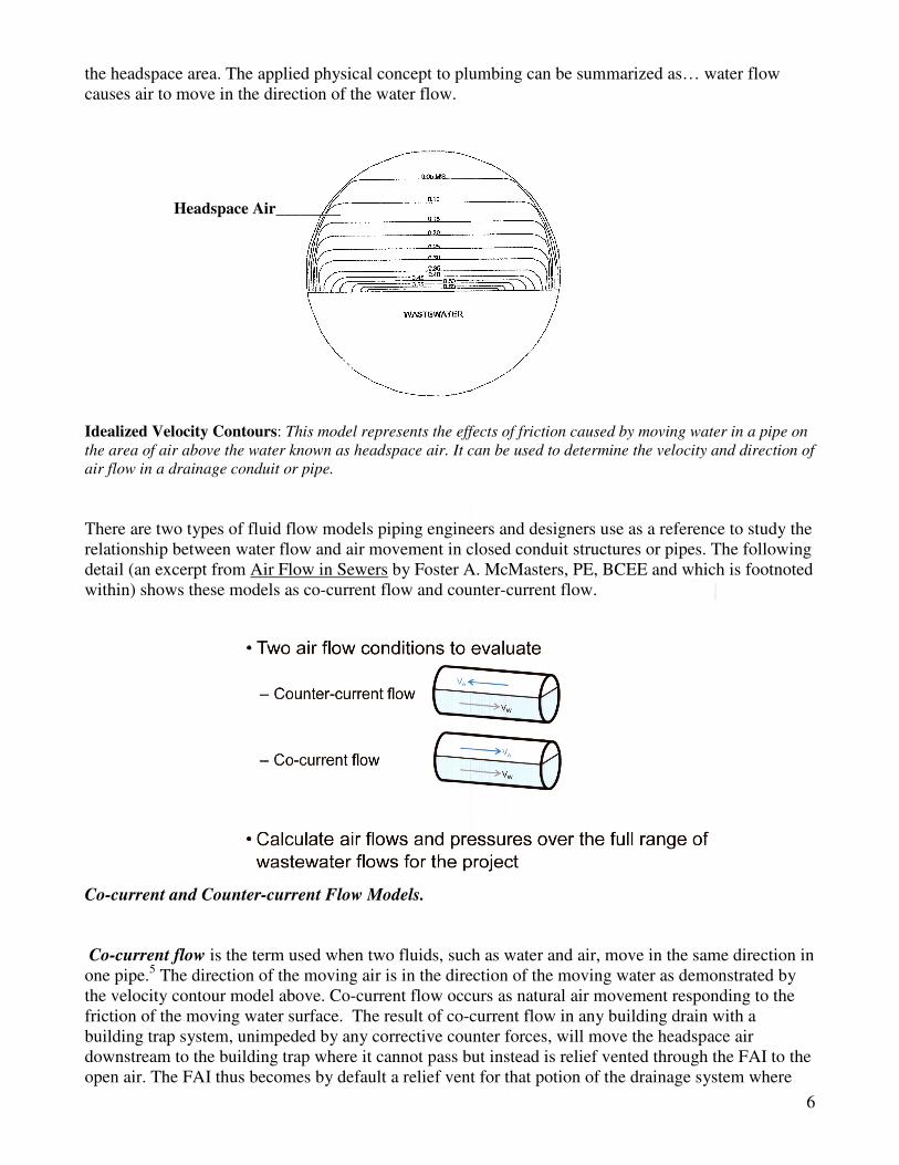
There are two types of fluid flow models piping engineers and designers use as a reference to study the
relationship between water flow and air movement in closed conduit structures or pipes. The following
detail (an excerpt from Air Flow in Sewers by Foster A. McMasters, PE, BCEE and which is footnoted
within) shows these models as co-current flow and counter-current flow.
Co-current and Counter-current Flow Models.
Co-current flow is the term used when two fluids, such as water and air, move in the same direction in
one pipe.5 The direction of the moving air is in the direction of the moving water as demonstrated by
the velocity contour model above. Co-current flow occurs as natural air movement responding to the
friction of the moving water surface. The result of co-current flow in any building drain with a
building trap system, unimpeded by any corrective counter forces, will move the headspace air
downstream to the building trap where it cannot pass but instead is relief vented through the FAI to the
open air. The FAI thus becomes by default a relief vent for that potion of the drainage system where

7
co-current flow exists. This is where sewer gases can escape from the system thereby creating a health
and safety concern for the users and suppliers of the utility service. Drawing SK-1 illustrates the
condition.
SK-1: Co-current flow at the Building Trap
Counter-current flow: The primary purpose of the FAI is to supply air into the building drain and
attending stacks thereby creating the second type of air flow that is referred to as counter-current
flow.6 This model demonstrates how wastewater moves in the direction of the downhill slope (gravity)
and towards the building trap while air moves in the opposite direction under the forces generated by
the plumbing stacks. The “stack effect”7 known and used for many centuries is a ventilation engine
without any moving parts. All that is needed is a conduit, or structure, or pipe with an opening at the
top and an opening at the bottom. Its physical presence will create a free, continuous and near
perpetual upward air movement. In plumbing design, the stack is employed for its simplicity and
effectiveness at creating counter-current flow within the piping system thereby providing for the
dilution and removal of unwanted and harmful gaseous by-products which form inside all waste piping
systems and which is commonly known and referred to as sewer gases. In the same way a chimney

8
removes the flue gases caused by the products of combustion, the plumbing stack removes the sewer
gases caused by the decomposition of organic matter. Drawing SK-2 demonstrates the condition
SK-2: Counter-current flow at the Building Trap
The components of the system (FAI + building drain + stack) work together to create an air ventilation
pathway, a system of admission and emission of air. The process can be summarized in the following
description. The vertical open pipe stack (sized large enough) creates a low pressure zone within the
vertical pipe and at all connections to it including the building drain. The low pressure is generated by
several natural occurring factors such as: differences in barometric pressure, temperature, humidity and
wind velocity. Since air will always move in the direction from high pressure to low pressure (basic
Science class) outside air at higher pressure will enter the building drain at the FAI and move towards
and up the stacks starting the counter-current flow in the building drain. The FAI, affected by the low
pressure forces generated in the building drain and ventilation stack, constantly replaces the air
removed by the stacks by drawing outside air into the system as it was originally designed. Other
model national codes (Uniformed Plumbing Code and National Plumbing Code) site similar
requirements of at least one 3” stack, undiminished in size, to the outside air to create the necessary
low pressure and ventilation within the plumbing system. Establishing counter-current flow in the
building drain pipe is critical for the proper functioning of the FAI. Drawing SK-3 illustrates the
condition.

9
SK-3: Counter-current flow in the building drain and stack. This drawing shows the airflow patterns of stack
effect. Outside air enters the FAI and travels through the building drain and the main stack to the outside. The
ventilation created by the stack reverses the frictional airflow cause by wastewater flow.

10
Consideration must be given to the location, size, number and length of stacks open to the outside. If a
single stack is located too far upstream from the FAI, or has been reduced to 1 ¼” – 2”, or has too long
a developed horizontal length, it may not be able to draft enough air to create counter-current flow due
to the friction loss developed between the building drain pipe wall and the forces created by the
friction of surface water flow. Once a stack overcomes these forces and is sufficiently drafting it can be
used to create ventilation in other parts of the piping system when connected to it. The naturally
occurring low pressure of the stack and upward movement of air across the opening of a branch vent
pipe or vent header connected to the open pipe stack will create low pressure and air movement in the
piping associated with the secondary vent. In large plumbing systems with multiple pipe risers coming
off of the same building drain, or where the building drain has a long developed length, it will be
necessary to provide additional main stacks that are full sized and open to the outside. This will ensure
countercurrent-flow in all parts of the building drain and overcome the friction loss associated with
long pipe runs. Additionally, it will assist in the ventilation of secondary vents (branch vents, common
vents, and vent headers) connected in the area of a main stack. To the contrary, restrictions in the
stacks ability to draft air upwards, such as size reduction, horizontal off-sets or a connection to an
AAV, will make friction loss more difficult or impossible to overcome. This condition will adversely
affect the amount air infiltration at the FAI. In exactly the same way that a deficient or restricted flue
pipe will result in flue gas spilling out of the vent draft diverter, deficient or restricted plumbing stacks
will result in the spillage of sewer gas at the FAI.
Air Admittance Valves and the affects on counter-current air flow in plumbing stacks and
building drains.
As stated in the previous sections of this report, the FAI can only function when there is sufficient
open pipe drafting within the piping system. It is the open plumbing stack that generates the upward
draft creating and sustaining the conditions of counter-current flow.
Contrary to open pipe systems, air admittance valve (AAV) venting systems function as atmospheric
vacuum breakers applied to plumbing drainage. Vacuum breaker technology is proven and works quite
well for the conditions of negative pressures and vacuums where they occur. Properly installed, it can
assist in the protection of the trap seal from the effects of siphoning only and thereby makes the claim
to protect the interior spaces from the harmful effects of sewer gases.
AAVs are one way devices that allow air into the drainage system (admission of air) but only when
there is a condition of negative pressure. The valve works intermittently, opening on negative pressure
and closing by gravity at neutral or positive pressure. The cycles (open /closed) can vary form a single
open/closed to several cycles depending on the vacuums created by the water flow of the pipe being
served.8
Since air admittance is minimal (long enough to break the vacuum) and intermittent (only when there
is a vacuum) there is no established pattern of air flow within the pipe it serves. In the pipes that have a
connection to an AAV, the air flow condition is static or stagnant under no water flow conditions.
However, upon water flow, air in contact with the water surface must move somewhere. According to
the examples of the velocity contour model, the headspace air would be dragged in the direction of the
water flow and crate a condition of co-current flow in the pipe. Air in front of the flowing water would
be pushed downstream to the stacks or to the building drain. At the same time, the AAV would break
any vacuums formed behind the water flow thus reducing any additional physical resistance to the
formation of a co-current flow. The air movement may be more turbulent but it must either continue in

11
the same direction as the water flow for as long as there is water flow (co-current flow) or churn within
the pipe. The only air flow pattern that can be established in an AAV system is co-current flow. When
water flow stops, air movement stops.
It is a designed engineering claim that there are no ventilated emissions involved with the use of
AAVs.9 For the same reason, fixture drains and stacks that use an AAV as the “vent” cannot create
counter-current flow in the pipe they are connected to nor can their use contribute to establishing
counter-current flow in the building drain. The use of stack-type AAVs close off the ventilation
patterns in stacks that are required and necessary in the systems where building traps and FAI’s are
present. Furthermore, conditions which impede the establishment of counter-current flow in the
building drain will result in air emissions somewhere. It has been demonstrated here that those
emissions find their way through the FAI carried by the effects of co-current flow of wastewater and
sewer gases. This condition as cited here is the result of venting changes in the 2010 NYS Plumbing
Code: the limited use of open pipe stack vent and vent stacks (903.1.2) and reduced sizing methods
(916.1, 2); the permitted use of stack-type air admittance valves (917.3); and the elimination of relief
vents on the horizontal drainage branch for fixture and group air admittance valves in systems of four
branch intervals or less (917.3.2).
Building vents and the 2010 NYS Plumbing Code
Section 903.1 Required vent extension. The vent system serving each building drain shall have at
least one vent pipe that extends to the outdoors.
903.1.1 Installation. The required vent shall be a dry vent…or an extension of a drain that connects to
the building drain…
903.1.2 Size. The required vent shall be sized in accordance with Section 916.2 based on required size
of building drain.
903.3 Vent termination. Every vent stack or stack vent shall terminate outdoors to the open air or to a
stack-type air admittance valve in accordance with Section 917.
Section 917.7 Vent required. Within each plumbing system, a minimum of one stack vent or vent
stack shall extend outdoors to the open air.
Section 916.1 Size of stack vents and vent stacks. The minimum required diameter of stack vents and
vent stacks shall be determined from the developed length and the total number of drainage fixture
units connected thereto in accordance with Table 916.1, but in no case shall the diameter be less than
one-half the diameter of the drain served or less than 1 ¼ inches.
Section 916.2 Vents other than stack vents and vent stacks. The diameter of individual vents,
branch vents, circuit vents and relief vents shall be at least ½ the diameter of the drain served.

12
To summarize the venting requirements above…the NYS Plumbing Code requires at least one stack to
the outside for each building drain or plumbing system. The installation of this single vent satisfies all
code requirements for outside air ventilation and allows all other vents (stack and fixture) to terminate
with AAVs. The vent may receive the waste water from fixtures, can be reduced to ½ the size of the
drainage portion of the stack or building drain and can be located anywhere off of the building drain or
portion of the building drain.
However, to satisfy the physical requirements for air infiltration through natural ventilation there needs
to be “stacking principles” written into the venting portion of the code. Engineering must consider the
location of the main stack, number of stacks, and its size relative to the air inlet opening. A main stack
must be undiminished in size and terminate to the open air if it is to overcome the physical drag and
resistance of the water flow and pipe walls. The lack or omission of these considerations in the venting
requirement allowed under the Plumbing Code removes the stacking and natural ventilation in the
plumbing system and makes the FIA by default a relief vent for the building drain.
The size of this singular open pipe vent is remarkably small considering the total number of fixture
units allowed to connect to the building drain. For example, you can have a single family home with 3
½ baths, kitchen and laundry on a 1 1/2” vent located anywhere in the system. A two story hotel with
100 rooms (500 dfu = drainage fixture units) can be built with only a single 2 inch vent, located off a
4” portion of the building drain and not exceeding 40 ft developed length. A 3 story multiple residence
with 48 dwelling units (10 dfu per/unit x 48 = 480 dfu) could be designed with a single 2 1/2” inch
vent, located off a 4” portion of the building drain and exceeding 40 ft in developed length. See SK-4
and SK-5, Apartment Complex, in Appendix, page 7.
In the above examples, the vents are sized according to 916.2 as required by 903.1 & 903.1.2. Section
916.2 Vents other than stack vents or vent stacks only deals with the sizes of: individual vents,
branch vents, circuit vents and relief vents. Therefore, the open pipe vent requirement in the code is
not for a stack. If you use Section 917.7 and install a stack vent or vent stack as implied, the size
differences are marginal. In both code sections there are no engineering principles employed to
accomplish “stack effect” venting. None of the open vent pipes mentioned in 916.2 or 917.7 would be
able to create a draft even in a small building let alone in a building drain where hundreds of fixture
units are flowing through the building trap.
So what exactly is the purpose of the “…at least one vent pipe that extends to the outdoors.”
requirement of Section 903? The manufactures of AAVs report that the primary purpose of the single
vent through the roof is to act as a relief vent for the positive pressures that will inevitably result within
building drains where AAVs are used.10
There can be many contributing factors relating to the
formation of positive pressure in plumbing systems. The Studor Company (manufactures of AAVs)
references a specific positive pressure condition termed “positive transient propagation” in their
Engineered Products Manual.11
The primary culprit of positive transient propagation is the discharge
of water closets (toilets) into the vertical stacks. When the discharge reaches the base of the stack
where it connects to the building drain, the falling effluent forms a water curtain around trapped air
creating a condition of positive pressure or a positive transient. “Pressure transients are very simply
the physical communication of a condition at one point in a system to another point. This means that if
there is an event at point A then this information is communicated to point B some distance away by
means of a pressure wave. The wave moves much faster than the air in which it travels and can move
in any direction, not necessarily in the flow direction. In a pipe the speed at which an air transient
travels is the acoustic velocity, approx 1050 ft/sec.”12
13
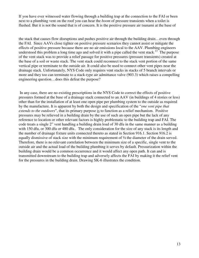
If you have ever witnessed water flowing through a building trap at the connection to the FAI or been
next to a plumbing vent on the roof you can hear the boom of pressure transients when a toilet is
flushed. But it is not the sound that is of concern. It is the positive pressure air tsunami at the base of
the stack that causes flow disruptions and pushes positive air through the building drain…even through
the FAI. Since AAVs close tighter on positive pressure scenarios they cannot assist or mitigate the
effects of positive pressure because there are no air emissions local to the AAV. Plumbing engineers
understood this problem a long time ago and solved it with a pipe called the vent stack.13
The purpose
of the vent stack was to provide a relief passage for positive pressures (pressure transients) created at
the base of a soil or waste stack. The vent stack could reconnect to the stack vent portion of the same
vertical pipe or terminate to the outside air. It could also be used to connect other vent pipes near the
drainage stack. Unfortunately, NYS Code only requires vent stacks in stacks of 5 branch intervals or
more and they too can terminate to a stack-type air admittance valve (903.3) which raises a compelling
engineering question…does this defeat the purpose?
In any case, there are no existing prescriptions in the NYS Code to correct the effects of positive
pressures formed at the base of a drainage stack connected to an AAV (in buildings of 4 stories or less)
other than for the installation of at least one open pipe per plumbing system to the outside as required
by the manufacture. It is apparent by both the design and specification of the “one vent pipe that
extends to the outdoors”, that its primary purpose is to function as a relief mechanism. Positive
pressures may be relieved in a building drain by the use of such an open pipe but the lack of any
reference to location or other relevant factors is highly problematic to the building trap and FAI. The
code treats a single 2” vent handling a building drain load of 30 dfu in the same manner as a building
with 150 dfu, or 300 dfu or 480 dfu.. The only consideration for the size of any stack is its length and
the number of drainage fixture units connected thereto as stated in Section 916.1. Section 916.2 is
equally dismissive of stack size with the minimum requirement of ½ the diameter of the drain served.
Therefore, there is no relevant correlation between the minimum size of a specific, single vent to the
outside air and the actual load of the building plumbing it serves by default. Pressurization within the
building drain would be a common occurrence and it would affect any open path. It can and is
transmitted downstream to the building trap and adversely affects the FAI by making it the relief vent
for the pressures in the building drain. Drawing SK-6 illustrates the condition.

14
SK-6 Conditions of positive pressures and co-current flow at the Building Trap. In this detail, water
flow from drainage stacks terminated with an AAV is shown. The path of airflow through the FAI is the
result of the combination of positive pressures created at the base of the stack and frictional air flow
caused by water flow.

15
Conclusion
The adverse affect of reduced open pipe ventilation on the function of the FAI is the result of a
condition of inadequate venting not capable of creating counter-current flow upstream of the building
trap. Sewer gas discharges at the FAI can be linked to several venting deficiencies found in the Code,
of which, the most common is the elimination of stack vents and vent stacks capable of creating
stacking effects. The use of alternative venting devices and methods involving: the use stack-type
AAVs and the elimination of relief venting for AAVs on fixture branch horizontal drains, are known to
stop upward movement of air in the pipes they serve. The use of these devices as venting systems
terminates the air flow patterns of natural draft and ventilation essential for systems designed for
building traps with FAI’s. The combination of AAVs and a single, reduced sized relief vent to the open
air results in conditions of co-current flow and pressurized air in the building drains. These same
conditions convert the FAI into a relief vent. The net effect is the emission of sewer gas to the
localized area of the FAI.
It is demonstrated here, that the use of the reduced venting methods and devices allowed by the 2010
NYS Plumbing Code is incompatible with the local conditions of building traps with fresh air inlets. It
is the desire and intention of the City of Ithaca to restore and retain the natural draft and ventilation
pattern of its sewer service laterals at the building trap and to eliminate potential problems associated
with unwanted and unplanned sewer gas discharge linked to the venting methods describes above.
AAVs will be permitted as published in the 2007 NYS Plumbing Code.
2) The public health and safety concerns of sewer gas accumulation within the building’s
plumbing system
One of the greatest concerns for the plumbing engineer is the protection of the public from the effects
of sewer gas. The challenge is not limited to the design and maintenance of public collection systems
but is a critical component of private collection systems (septic) and all interior plumbing systems.
Every model plumbing code requires the use of a water seal at the fixture trap to protect the user from
the harmful affects of sewer gases because….sewer gas exists in all plumbing systems.
The Anatomy of Sewer Gas
Sewer gases are, at the very least, an odor nuisance but they are also a public health concern. These
gases are formed as the result of human and other wastes decaying in the sanitary piping system. The
wastes turn “septic”…that is they are broken down by the presence of bacterial organisms as soon as it
enters the drain pipe. The by-products of this septic action are gases and bio-films that form on the
interior of the pipe. Some of the substances that can be found within these bio-films and gases are:
Methane (flammable), Hydrogen Sulfide (toxin), Ammonia (toxic), Carbon Dioxide (asphyxiates), and
Biological Pathogens contained in human waste, blood and tissue (health concerns).

16
An excerpt form an article posted to the web site of the International Association of Certified Home
Inspectors summarizes the concerns associated with sewer gases.
Sewer gases pose the following risks to building occupants:
• hydrogen sulfide poisoning. Hydrogen sulfide is an explosive and extremely toxic gas that can impair
several different systems in the body at once, most notably the nervous system. So potent that it can be
smelled at 0.47 parts per billion by half of human adults, the gas will begin to cause eye irritation at 10
parts per million (ppm) and eye damage at 50 ppm. Other low-level symptoms include nervousness,
dizziness, nausea, headache and drowsiness. Exposure to higher concentrations can lead to pulmonary
edema, and still higher levels (800 to 1,000 ppm) will cause almost immediate loss of consciousness and
death;
• asphyxiation. When sewer gases diffuse into household air, they gradually displace oxygen and
suffocate occupants. The effects of oxygen deficiency include headache, nausea, dizziness and
unconsciousness. At very low oxygen concentrations (less than 12%), unconsciousness and death will
occur quickly and without warning. Oxygen will be at its lowest concentrations in the basement, which
is where heavy sewer gases, principally methane, are likely to collect;
• fire or explosion. Methane and hydrogen sulfide are explosive components of sewer gas. Vapors from
improperly disposed fuel can further increase the risk of fire or explosion; and
• odor. Hydrogen sulfide is responsible for sewer gas’s characteristic rotten-egg smell, which can be
overbearing even at extremely low concentrations. The gas’s odor is a safeguard, however, because it
alerts building occupants to the leak long before they’re in any serious danger. It is important to note
that at roughly 100 ppm, the olfactory nerve becomes paralyzed, removing the victim’s sense of smell
and, subsequently, their awareness of the danger. Another "warning smell" comes from ammonia, which
will sear the nostrils and progressively irritate the mucous membranes and respiratory tract. This gas,
unlike hydrogen sulfide, is sufficiently irritating that building occupants are likely to vacate before its
concentration rises to toxic levels.14
In a well designed plumbing piping system these substances and gases are constantly being diluted
with incoming air from the FAI and removed by the “stacking effect” through the roof and to the
outside. Open pipe venting and air circulation within a plumbing system is a critical plumbing
engineering feature and one that is driven by the concerns for health and safety. Here, the term venting
is a physical process that allows air to enter and leave or allow for the admission and emission of air
from and to the outside of the building structure. The primary function of venting can be best described
as a two-fold process. First, venting allows the piping system to self regulate the negative and positive
pressures that are created in the piping system when water, waste and solids flow through a pipe. The
regulation of pressures is needed to maintain the water seals of fixture traps. The second function of
the vent is to allow the sewer gases to escape through ventilation to the outside air. AAVs are intended
to accomplish one of the first functions of trap seal protection by opening (admission only) on a
negative pressure to relieve a siphon which may affect the water seal of a trap. It is the second function
of the venting system, the ventilation of sewer gases, which an AAV cannot perform. Nevertheless, the
2010 NYS Plumbing Code permits AAVs to be included as plumbing “vents” for all fixtures and
piping. The result is that potentially harmful and unwanted sewer gases remain within the piping
system.

17
As discussed before, the movement of air in pipes connected to an AAV during conditions of no water
flow is static and stagnant since there are no external forces affecting air movement within the pipe.
Water flow will create air movement in a co-current pattern with the water but air movement stops
when water flow stops. The required relief vent of the plumbing system (903.1) can assist to relieve
localized positive pressures relative to its location near the base of the active stack and building drain
but it has no effect on the air movement in the active stack or other stacks terminating with an AAV.
Stacks using an AAV as its termination point become essentially closed systems. Air flow is minimal,
reacting only to vacuums and intermittent water flow. The question that must be asked of the plumbing
engineer and of public officials charged with ensuring the public health and safety is…where does the
sewer gas go?
The research and analysis here leads us to conclude that most of the sewer gases and odors in an AAV
“vented” system remain in the piping system. Each riser, horizontal drain and building drain would
contain and retain the byproducts of decomposing waste. The lack of any counter-current air flow will
trap the sewer gases in unventilated pipes located in the walls, ceilings, floors, attics and basements of
all buildings that utilize these AAV “venting” techniques.
Other aspects relating to the characteristics of sewer gases need to be addressed. Two substances
commonly found in sewer gas are methane and ammonia. Each can have a molecular weight lighter
than air.15
Applying this principle to the conditions known to exist in the AAV venting systems,
methane and ammonia can migrate to the upper portions of plumbing risers. This would be true with
any substance with properties that have vapor densities lighter than air and are produced as byproducts
of the waste stream. Substances that are heavier (Hydrogen Sulfide and Carbon Dioxide)16
would
migrate to the lower portions of stacks and building drains where they may be forced out by positive
pressures in the building drain. However, this would be minimal given the limited amount of air flow
conditions and the limited number of outlet points (903.1) connected to the building drain in AAV
vented systems and the existence of the building trap that will prohibit these gases to pass….except
through the FAI. Therefore, all risers, stacks and building drains in plumbing systems closed to the
process of air emission are potential havens for harmful sewer gases. See Apartment Complex – Areas
of unventilated sewer gases in AAV vented systems , in Appendix, page 10.
The processes of aerobic and anaerobic digestion also play a role in the composition and
concentrations of gases formed in the plumbing system. In an open vent pipe system that has an
established pattern of counter-current flow throughout all portions of the piping, oxygen is constantly
present to assist in the rapid breakdown of microorganisms in the waste stream while upward drafts
remove the gases to the outside. Conversely, when oxygen is scarce as in an essentially closed AAV
venting system, anaerobic digestion will occur in reaction to the breakdown of the organic matter
contained in sewage. The anaerobic process will result in higher concentrations of methane, carbon
dioxide and hydrogen sulfide in the pipe environment where digestion takes place.17
The combination
of minimal air flow and the production of anaerobic by-products can be a potentially dangerous
situation occurring silently within the building plumbing.
Most reported causes of sewer gas infiltration in buildings are associated with dry traps, cracked vent
pipes or plugged vent. Regardless of the cause, sewer gas infiltration from a fully ventilated open pipe
system may not be the same as infiltration from an AAV vented system. Continuously ventilated
systems would be expected to have less potent substances or concentrations under aerobic conditions
because the headspace air in the piping is affected by constant dilution from outside air. While an AAV
vent system would tend to have higher and more potent concentrations of sewer gas substances
resulting from the absence of effective dilution, minimal or stagnant air flow, and anaerobic
conditions. A comparison of the two venting systems, open pipe venting and AAV venting, is

18
illustrated in drawings Residence A & Residence B, in the Appendix pages 8 &9. Each shows the
ventilated and unventilated sections of the plumbing system and areas of sewer gas discharges in a
typical residential home. The Apartment Complex drawing (a typical of one section of a much larger
complex) shows the areas of unventilated sewer gases in the AAV vented system, Appendix, page 13.
It demonstrates the enormous area of DWV piping having no emission capabilities when built in
compliance with Sections 903.1 and 917.7, 2010 NYS Plumbing Code.
This may help to explain why there has been an increased interest on behalf of members of the local
plumbing community regarding the use of AAV venting systems. Although anecdotal now, the number
of sewer gas related incidences casually referenced during the normal course of business through my
office is noticeable. Most accounts involve a breaching of an existing portion of the plumbing system
where an AAV was installed. All involved a rapid discharge of sewer gas and odors at the unwitting
moment of the breach and in some cases the workers had to evacuate the space.
Beyond the anecdotal, we can rely on the existing body of scientific knowledge and physics to
understand and explain the existence of sewer gases in buildings. No one needs to drop a bowling ball
off a 10 story building to discover…will it fall? Likewise, we already know the answer to the
question…where does the sewer gas go? We all know that sewer gas is present. We also know that an
open pipe ventilation system will dilute and remove sewer gas from the building sanitary piping
system…an AAV system cannot. It appears that not all venting systems are equal and some can have
potentially serious side effects. The position of the City of Ithaca, NY and the recommendation of this
report is that any plumbing code that does not address and mitigate the real problems associated with
the presence and formation of sewer gas within our buildings is substandard and unacceptable. As
public officials, if we know sewer gas can be harmful to the occupants of a building, and we know that
it is present, then its removal is an obligation not an option. That is our Legislative Intent.
It is unfortunate, but most people do not understand the principles of plumbing ventilation. Instead,
they rely on our professional experience and judgment to provide acceptable levels of safety. It is in
the realm of safeguarding the “public trust” that policy decisions are given their true legitimacy. If we
allow standing as fact something that is only partially true, or worse, we change the definitions to make
it true, then how does that effect the “public trust”? With all condor and respect to our professional
responsibilities, and in the interest of full disclosure of the facts relating to this matter, substantiated
with the evidence presented here, I report to you that the AAV is not a “vent”. To make that claim is
intellectually dishonest and misleading to the public. Changing the definition of a vent system (NYS
Plumbing Code, Section 202 General Definitions) so that AAVs could be included by adding the
wording “…pipes installed to provide a flow of air to or from a drainage system…” does not make it a
vent nor does it solve the problems we have cited here.
It seriously undermines the objective of public health and safely, including the public trust, when
building officials must enforce as being in full compliance, code prescriptions that are known to have
half functional aspects of performance. Worse, is to have public officials not recognize or fail to
understand the differences. So what is the cost of sacrificing the public trust?
The City of Ithaca is concerned about the harmful effects of sewer gas. We are committed to passing
reasonable and effective local legislation so that these contaminants can be effectively removed from
within the building structures by the application of long standing and universally accepted plumbing
engineering practices of open pipe ventilation. We ask the Code Council’s support in adoption as a
more restrictive local standard in this matter. If the Council feels that this issue is worth statewide
review, we offer our assistance.

19
1 In this report, the term open pipe ventilation is used to describe a piping system that uses an arrangement of vertical pipes
connected to the building drain which terminate through the roof of a building to the outside air. Secondary pipes connected
to these vertical pipes are also considered to be an open pipe. The purpose of open pipe ventilation is the protection of
fixture traps by the regulation of siphon and back pressures within the piping system and the circulation of air for the
dilution and removal of sewer gases to the outside air.
2 WERF, Minimization of Odors and Corrosion in Collection Systems, Chapter 6, 6.2.1, Theoretical Dynamics of
Wastewater Conduits. Although this document is intended to present usable data to assist the designers, operators and
engineers of public collection systems, the physical and scientific analysis presented is relevant to all pipe collection
systems and is a valuable primer toward the understanding of the characteristics of wastewater and air flow within a pipe.
3 Ibid.
4 Pescod, M.B. and Price, A.C. 1982. Major Factors in Sewer Ventilation. Journal of the Water Pollution Control
Federation, 1982. Vol 54, No. 4.
5 Air Flow in Sewers. Approach to Design Sewers for both Air and Water, OWEA 2012 Collection Specialty Conference,
May 10, 2012. Foster A. McMasters, Jr., PE, BCEE
6 Ibid. Formulas for co-current and counter-current flows, page 10.
7 Wikipedia, Stack effect is the movement of air into and out of buildings, chimneys, flue gas stacks, or other containers,
and is driven by buoyancy. Buoyancy occurs due to a difference in indoor-to-outdoor air density resulting from temperature
and moisture differences. The result is either a positive or negative buoyancy force. The greater the thermal difference and
the height of the structure, the greater the buoyancy force, and thus the stack effect. The stack effect is also referred to as
the "chimney effect", and it helps drive natural ventilation and infiltration.
8 Studor, Engineering Products Manual, 5
th Edition, Introduction to the Positive Air Pressure Attenuator (PAPA), page 14,
Stuo13-Rev 12-09.
9 Ibid, Introduction to Air Admittance Valves (AAVs), page 12.
10
Ibid, , Introduction to the Positive Air Pressure Attenuator (PAPA),page 13
11
Ibid, page 14.
12
Ibid, page 14.
13
American Society of Plumbing Engineers, Data Book, A Plumbing Engineers Guide to Systems Design and
Specifications, Volume 2, Chapter 1, Flow in Stacks, Building Drains and Fixture Drains, page 2,
14
Sewer Gases in the Home - InterNACHI http://www.nachi.org/sewer-gases-home.htm#ixzz22OrfahqZ
15
Meridian Engineering & Technology-Consulting Engineers & Scientists, Reference Data Sheet on Sewer Gas(es),
November 1993. Table 1- Selected Properties of Sewer Gases.
16
Ibid.
17
Fergusen, T. & Mah, R. (2006) Methanogenic bacteria in Anaerobic digestion of biomass, p49.