Embed Size (px)
Citation preview
IJRET: International Journal of Research in Engineering and Technology eISSN: 2319-1163 | pISSN: 2321-7308
_______________________________________________________________________________________
Volume: 04 Issue: 07 | July-2015, Available @ http://www.ijret.org 26
ANALYSIS OF MULTI-TERMINAL HVDC TRANSMISSION SYSTEM
FEEDING VERY WEAK AC NETWORKS
S. Singaravelu1, S. Seenivasan
2
1Professor, Department of Electrical Engineering, Annamalai University, Annamalai Nagar-608002, Tamilnadu,
India 2Assistant Professor, Department of Electrical Engineering, Annamalai University, Annamalai Nagar-608002,
Tamilnadu, India
Abstract This paper presents a line commutated converter (LCC) based multi-terminal HVDC transmission (MTDC) system feeding very
weak AC networks with hybrid reactive power compensators (RPC’s) at the inverter AC side. The hybrid compensator is
accomplished by the equal mixing of any two of the following compensators: synchronous compensator (SC); static var
compensator (SVC); static synchronous compensator (STATCOM). The four-terminal HVDC transmission system model is
implemented in the Matlab with the firefly algorithm based optimal proportional integral (PI) controller for rectifiers and
inverters control. The transient performances of hybrid RPC’s (SC+SVC, SVC+STATCOM and SC+STATCOM) are studied
under various fault conditions and the results are compared with the performance of the SC, SVC and STATCOM to focus the
high quality of the hybrid compensators. The simulation results authorize that the equivalent mixture of SC and STATCOM has a
steady and fastest response. The results also reveal the supremacy of the firefly algorithm based optimal PI controller over the
conventional PI controller. The harmonic present in the inverter side AC quantities is also calculated under steady state operation to assure the quality of power supply.
Keywords: MTDC, Very weak AC system, Hybrid RPC, PI controller, Firefly Algorithm.
--------------------------------------------------------------------***----------------------------------------------------------------------
1. INTRODUCTION
Due to the flexibility in the power flow control, reduction in
number of converter units and easy connection of a new
offshore load/generation terminal [1-3], the MTDC power
transmission technology has attracted a number of researchers. During occurrence of the fault, in an MTDC
system without appropriate control and protection, the fault
at one terminal will affect the other terminals. Under such
circumstances of the MTDC system, by presuming that the
blocking of the converter is successful, special control and
protection is offered. On the other hand, this presumption is
not necessarily valid in terms of the practical operation of
converters in the HVDC system [4-6]. Hence, it is worth
identifying the possible hazard to the MTDC system by
propagating the fault at one terminal without blocking the
converters. During such situations, the fault recovery time and level of temporary over voltage (TOV) are the major
criterion to be studied, which are often decided by the
performance of reactive power compensator at AC side and
PI controllers on the DC system. Therefore, investigating
the performance of those devices is necessary to reveal the
control and protection.
Further, the behavior of HVDC systems plays ever greater
roles in the performance of entire AC/DC power systems.
In order to improve stability of the power grid consists of
HVDC system, it is necessary to know the mechanisms of
the interactions between an HVDC system and an AC
network. The importance of this interaction basically
depends on the strength of the AC system at the converter bus [7], which is typically shown by short circuit ratio
(SCR). The following SCR values[8] can be applied to
classify AC systems: a) a strong AC system SCR >3, b) a
weak AC system 2 ≤ SCR < 3, c) a very weak AC system
SCR < 2.
Numerous works have been practiced to identify the
interaction between very weak AC networks and HVDC
systems. The performance of the monopolar HVDC system
is analyzed with dynamic voltage control devices[9] such as
fixed capacitor (FC), SC, SVC and a mix of the SC and
SVC at the inverters of very weak AC systems under AC and DC disturbances. The possibility to interconnect
AC/DC systems, leading to very weak SCR [10], is exposed
by allowing the STATCOM for reactive power
compensation. A multilevel gate turn-off (GTO) thyristor
inverter as an advanced static var compensator [11] is
projected for a monopolar HVDC system and tinted its main
benefits. The suppressors of temporary over voltage (TOV)
and DC power recovery performance of the advanced static
var compensator is investigated at an HVDC converter
terminal with very low SCR AC system and the simulation
results are compared under various AC and DC disturbances with the reactive power compensation options available.
IJRET: International Journal of Research in Engineering and Technology eISSN: 2319-1163 | pISSN: 2321-7308
_______________________________________________________________________________________
Volume: 04 Issue: 07 | July-2015, Available @ http://www.ijret.org 27
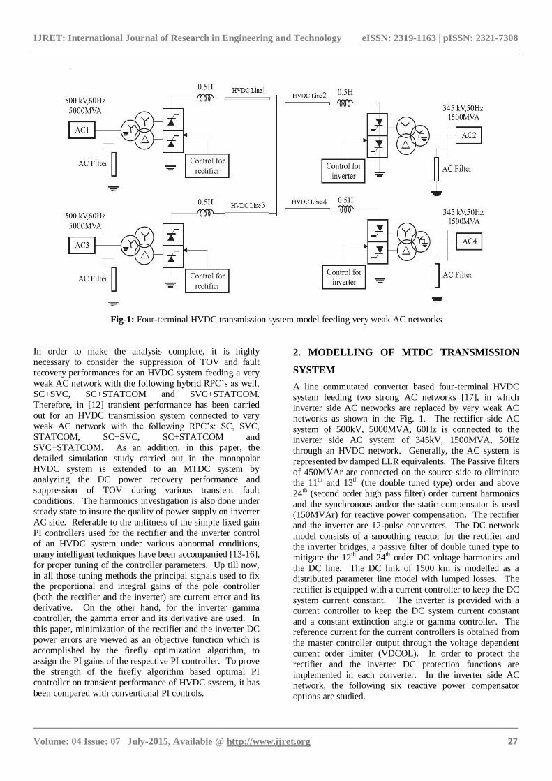
Fig-1: Four-terminal HVDC transmission system model feeding very weak AC networks
In order to make the analysis complete, it is highly
necessary to consider the suppression of TOV and fault
recovery performances for an HVDC system feeding a very
weak AC network with the following hybrid RPC‟s as well,
SC+SVC, SC+STATCOM and SVC+STATCOM.
Therefore, in [12] transient performance has been carried
out for an HVDC transmission system connected to very
weak AC network with the following RPC‟s: SC, SVC,
STATCOM, SC+SVC, SC+STATCOM and
SVC+STATCOM. As an addition, in this paper, the
detailed simulation study carried out in the monopolar HVDC system is extended to an MTDC system by
analyzing the DC power recovery performance and
suppression of TOV during various transient fault
conditions. The harmonics investigation is also done under
steady state to insure the quality of power supply on inverter
AC side. Referable to the unfitness of the simple fixed gain
PI controllers used for the rectifier and the inverter control
of an HVDC system under various abnormal conditions,
many intelligent techniques have been accompanied [13-16],
for proper tuning of the controller parameters. Up till now,
in all those tuning methods the principal signals used to fix the proportional and integral gains of the pole controller
(both the rectifier and the inverter) are current error and its
derivative. On the other hand, for the inverter gamma
controller, the gamma error and its derivative are used. In
this paper, minimization of the rectifier and the inverter DC
power errors are viewed as an objective function which is
accomplished by the firefly optimization algorithm, to
assign the PI gains of the respective PI controller. To prove
the strength of the firefly algorithm based optimal PI
controller on transient performance of HVDC system, it has
been compared with conventional PI controls.
2. MODELLING OF MTDC TRANSMISSION
SYSTEM
A line commutated converter based four-terminal HVDC system feeding two strong AC networks [17], in which
inverter side AC networks are replaced by very weak AC
networks as shown in the Fig. 1. The rectifier side AC
system of 500kV, 5000MVA, 60Hz is connected to the
inverter side AC system of 345kV, 1500MVA, 50Hz
through an HVDC network. Generally, the AC system is
represented by damped LLR equivalents. The Passive filters
of 450MVAr are connected on the source side to eliminate
the 11th and 13th (the double tuned type) order and above
24th (second order high pass filter) order current harmonics
and the synchronous and/or the static compensator is used (150MVAr) for reactive power compensation. The rectifier
and the inverter are 12-pulse converters. The DC network
model consists of a smoothing reactor for the rectifier and
the inverter bridges, a passive filter of double tuned type to
mitigate the 12th and 24th order DC voltage harmonics and
the DC line. The DC link of 1500 km is modelled as a
distributed parameter line model with lumped losses. The
rectifier is equipped with a current controller to keep the DC
system current constant. The inverter is provided with a
current controller to keep the DC system current constant
and a constant extinction angle or gamma controller. The reference current for the current controllers is obtained from
the master controller output through the voltage dependent
current order limiter (VDCOL). In order to protect the
rectifier and the inverter DC protection functions are
implemented in each converter. In the inverter side AC
network, the following six reactive power compensator
options are studied.
IJRET: International Journal of Research in Engineering and Technology eISSN: 2319-1163 | pISSN: 2321-7308
_______________________________________________________________________________________
Volume: 04 Issue: 07 | July-2015, Available @ http://www.ijret.org 28
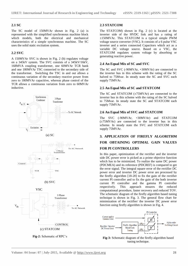
2.1 SC
The SC model of 150MVAr shown in Fig. 2 (a) is
represented with the simplified synchronous machine block
which models, both the electrical and mechanical
characteristics of a simple synchronous machine. The SC
uses the solid static excitation system.
2.2 SVC
A 150MVAr SVC is shown in Fig. 2 (b) regulates voltage on a 345kV system. The SVC consists of a 345kV/16kV,
168MVA coupling transformer, one 60MVAr TCR bank
and one 180MVAr TSC connected to the secondary side of
the transformer. Switching the TSC in and out allows a
continuous variation of the secondary reactive power from
zero to 180MVAr capacitive, whereas phase control of the
TCR allows a continuous variation from zero to 60MVAr
inductive.
Vf mExcitation
To AC Network
0Pm
3 Phase
Transformer
Synchronous
Condenser
(a) SC
To AC Network
3 PhaseTransformer
Control
TCR TSC
(b) SVC
To AC Network
CONTROL
Vdc
VSC
3 Phase
Transformer
(c) STATCOM
Fig-2: Schematic of RPC„s
2.3 STATCOM
The STATCOM) shown in Fig. 2 (c) is located at the
inverter side of the HVDC link and has a rating of
±150MVAr. This STATCOM is a typical simple PWM
voltage source converter (VSC). It consists of a 6 pulse VSC
inverter and a series connected Capacitors which act as a
variable DC voltage source. Based on a VSC, the STATCOM regulates system voltage by absorbing or
generating reactive power.
2.4 An Equal Mix of SC and SVC
The SC and SVC (-90MVAr, +30MVAr) are connected to
the inverter bus in this scheme with the rating of the SC
halved to 75Mvar. In steady state the SC and SVC each
supply 75MVAr.
2.5 An Equal Mix of SC and STATCOM
The SC and STATCOM (±75MVAr) are connected to the
inverter bus in this scheme with the rating of the SC halved
to 75Mvar. In steady state the SC and STATCOM each
supply 75MVAr.
2.6 An Equal Mix of SVC and STATCOM
The SVC (-90MVAr, +30MVAr) and STATCOM (±75MVAr) are connected to the inverter bus in this
scheme. In steady state the SVC and STATCOM each
supply 75MVAr.
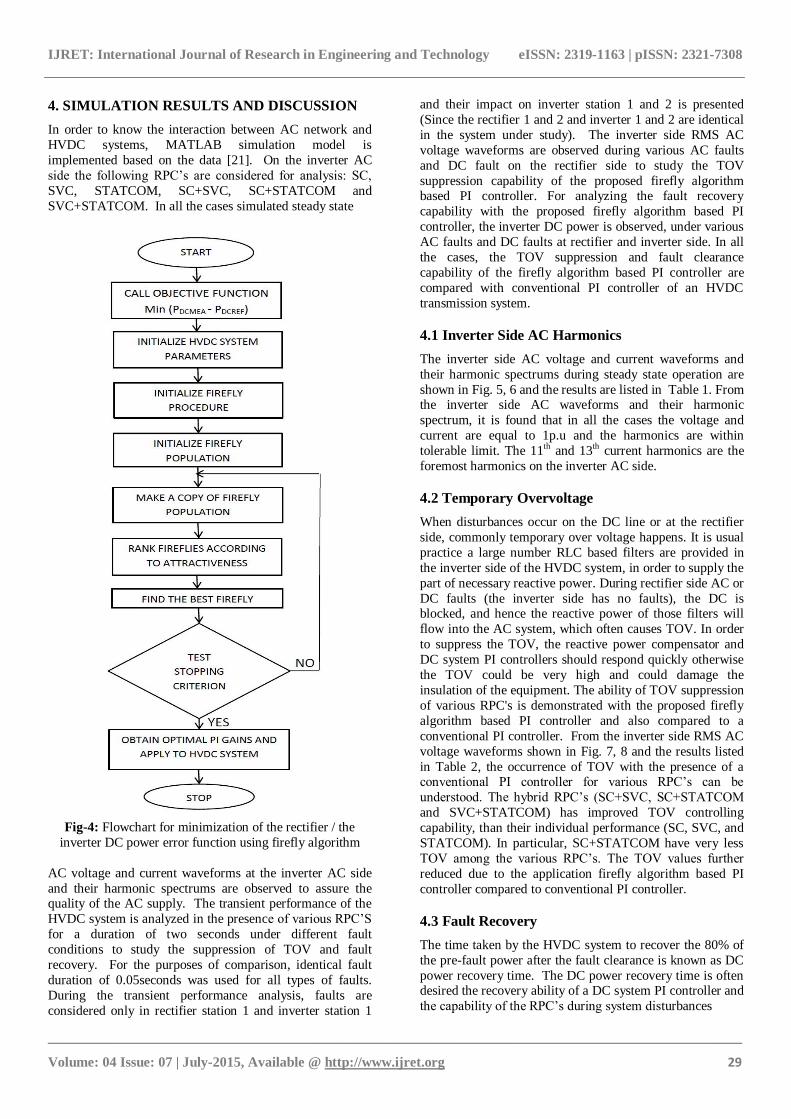
3. APPLICATION OF FIREFLY ALGORITHM
FOR OBTAINING OPTIMAL GAIN VALUES
FOR PI CONTROLLERS
In this paper, optimization of the rectifier and the inverter
side DC power error is picked as a prime objective function
which has to be minimized. To realize the same DC power
(PDCMEA) and its reference (PDCREF) is compared to get
the error signal. The integral square error of the rectifier DC
power error and inverter DC power error are processed by
the firefly algorithm [18-20] to fix the gain of the rectifier
current PI controller and to fix the gain of the both inverter
current PI controller and the gamma PI controller respectively. This approach ensures the reduced
computational procedure, faster recovery and reduced TOV.
The schematic diagram of the firefly algorithm based tuning
technique is shown in Fig. 3. The general flow chart for
minimization of the rectifier/ the inverter DC power error
function using firefly algorithm is shown in Fig. 4.
Fig-3: Schematic diagram of the firefly algorithm based
tuning technique.
IJRET: International Journal of Research in Engineering and Technology eISSN: 2319-1163 | pISSN: 2321-7308
_______________________________________________________________________________________
Volume: 04 Issue: 07 | July-2015, Available @ http://www.ijret.org 29
4. SIMULATION RESULTS AND DISCUSSION
In order to know the interaction between AC network and
HVDC systems, MATLAB simulation model is
implemented based on the data [21]. On the inverter AC
side the following RPC‟s are considered for analysis: SC,
SVC, STATCOM, SC+SVC, SC+STATCOM and
SVC+STATCOM. In all the cases simulated steady state
Fig-4: Flowchart for minimization of the rectifier / the
inverter DC power error function using firefly algorithm
AC voltage and current waveforms at the inverter AC side
and their harmonic spectrums are observed to assure the quality of the AC supply. The transient performance of the
HVDC system is analyzed in the presence of various RPC‟S
for a duration of two seconds under different fault
conditions to study the suppression of TOV and fault
recovery. For the purposes of comparison, identical fault
duration of 0.05seconds was used for all types of faults.
During the transient performance analysis, faults are
considered only in rectifier station 1 and inverter station 1
and their impact on inverter station 1 and 2 is presented
(Since the rectifier 1 and 2 and inverter 1 and 2 are identical
in the system under study). The inverter side RMS AC
voltage waveforms are observed during various AC faults
and DC fault on the rectifier side to study the TOV
suppression capability of the proposed firefly algorithm based PI controller. For analyzing the fault recovery
capability with the proposed firefly algorithm based PI
controller, the inverter DC power is observed, under various
AC faults and DC faults at rectifier and inverter side. In all
the cases, the TOV suppression and fault clearance
capability of the firefly algorithm based PI controller are
compared with conventional PI controller of an HVDC
transmission system.
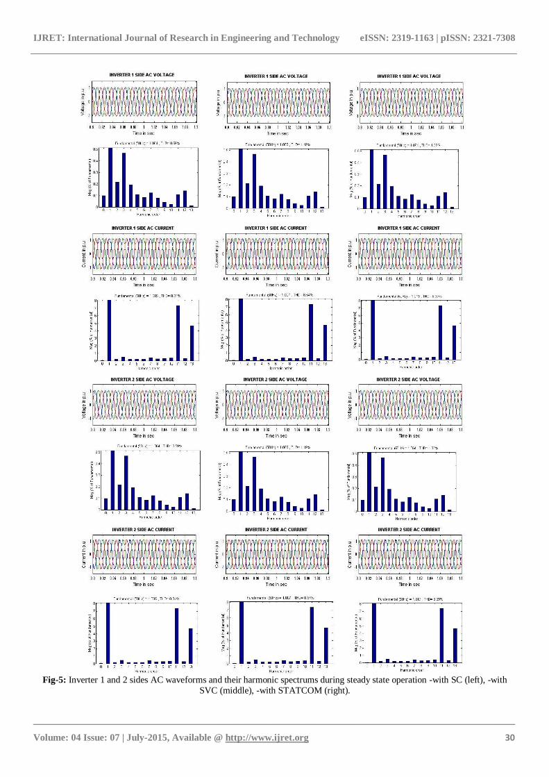
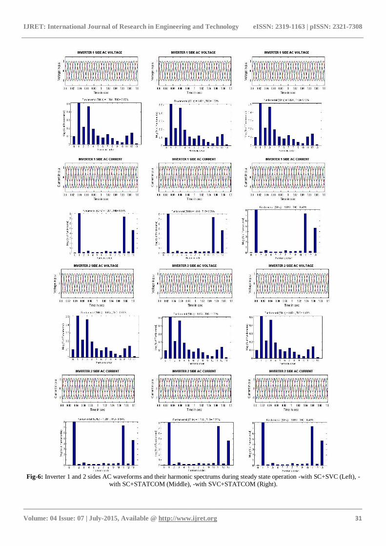
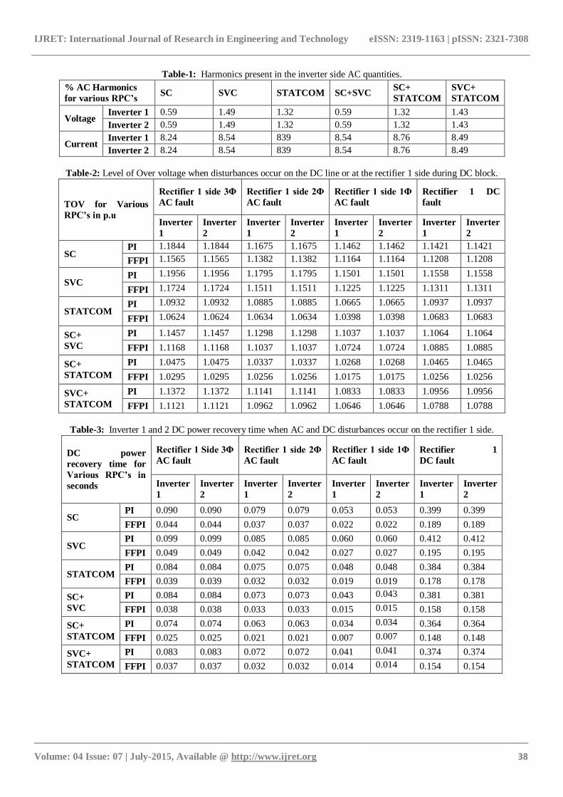
4.1 Inverter Side AC Harmonics
The inverter side AC voltage and current waveforms and
their harmonic spectrums during steady state operation are
shown in Fig. 5, 6 and the results are listed in Table 1. From the inverter side AC waveforms and their harmonic
spectrum, it is found that in all the cases the voltage and
current are equal to 1p.u and the harmonics are within
tolerable limit. The 11th and 13th current harmonics are the
foremost harmonics on the inverter AC side.
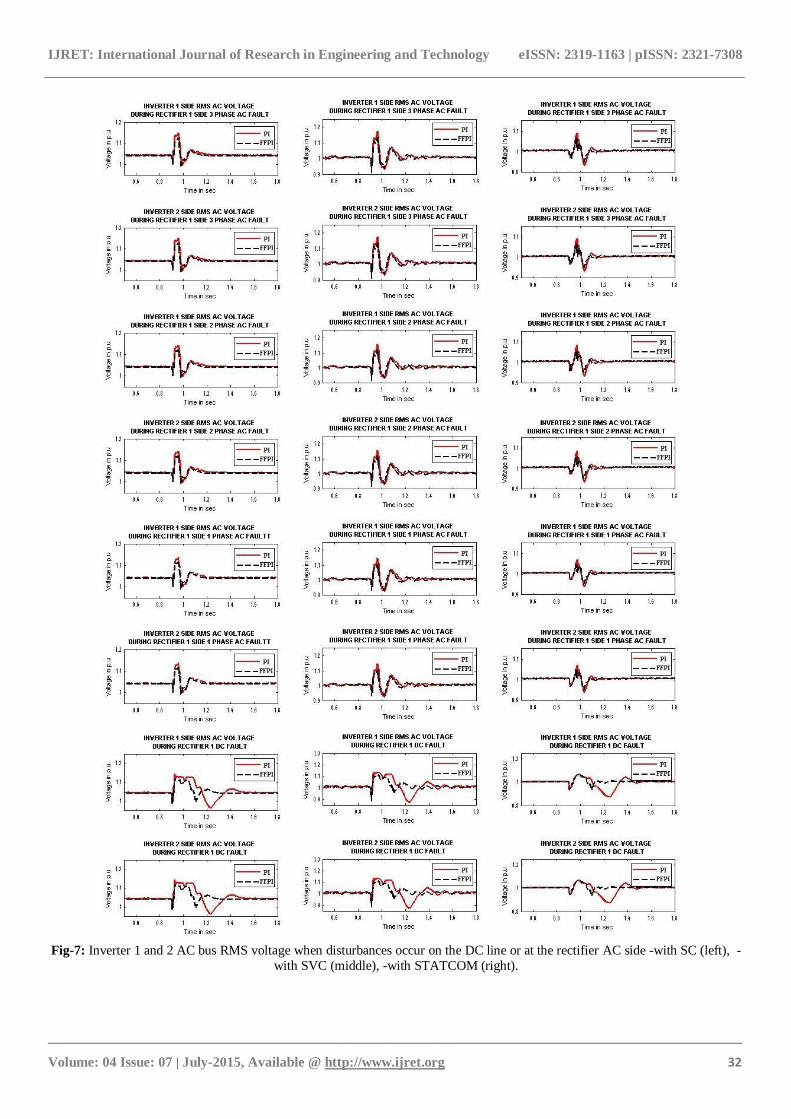
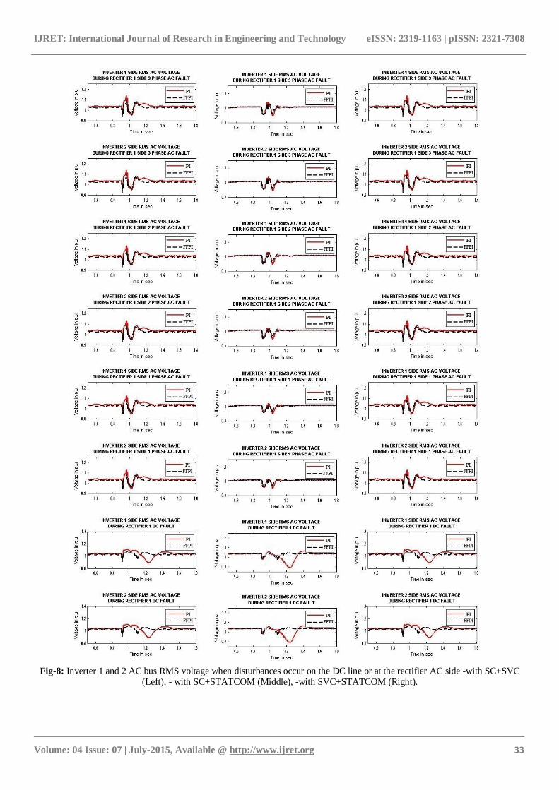
4.2 Temporary Overvoltage
When disturbances occur on the DC line or at the rectifier
side, commonly temporary over voltage happens. It is usual
practice a large number RLC based filters are provided in
the inverter side of the HVDC system, in order to supply the
part of necessary reactive power. During rectifier side AC or
DC faults (the inverter side has no faults), the DC is blocked, and hence the reactive power of those filters will
flow into the AC system, which often causes TOV. In order
to suppress the TOV, the reactive power compensator and
DC system PI controllers should respond quickly otherwise
the TOV could be very high and could damage the
insulation of the equipment. The ability of TOV suppression
of various RPC's is demonstrated with the proposed firefly
algorithm based PI controller and also compared to a
conventional PI controller. From the inverter side RMS AC
voltage waveforms shown in Fig. 7, 8 and the results listed
in Table 2, the occurrence of TOV with the presence of a conventional PI controller for various RPC‟s can be
understood. The hybrid RPC‟s (SC+SVC, SC+STATCOM
and SVC+STATCOM) has improved TOV controlling
capability, than their individual performance (SC, SVC, and
STATCOM). In particular, SC+STATCOM have very less
TOV among the various RPC‟s. The TOV values further
reduced due to the application firefly algorithm based PI
controller compared to conventional PI controller.
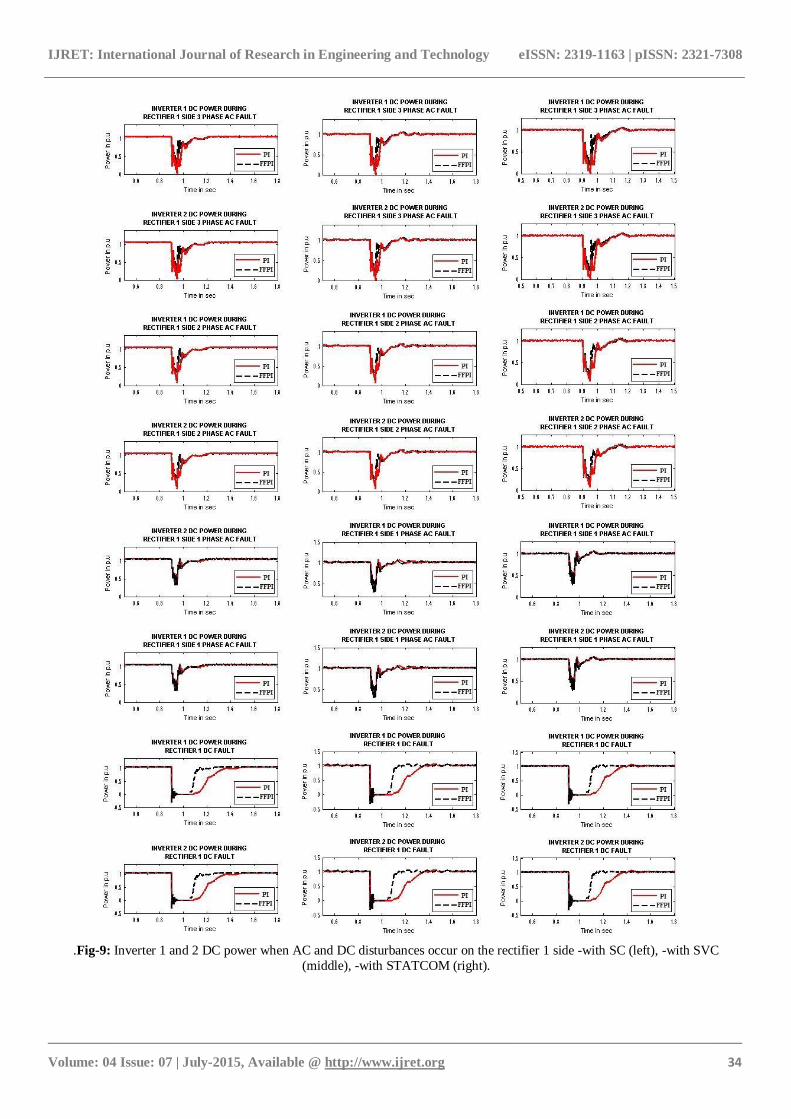
4.3 Fault Recovery
The time taken by the HVDC system to recover the 80% of
the pre-fault power after the fault clearance is known as DC
power recovery time. The DC power recovery time is often desired the recovery ability of a DC system PI controller and
the capability of the RPC‟s during system disturbances
IJRET: International Journal of Research in Engineering and Technology eISSN: 2319-1163 | pISSN: 2321-7308
_______________________________________________________________________________________
Volume: 04 Issue: 07 | July-2015, Available @ http://www.ijret.org 30
Fig-5: Inverter 1 and 2 sides AC waveforms and their harmonic spectrums during steady state operation -with SC (left), -with
SVC (middle), -with STATCOM (right).
IJRET: International Journal of Research in Engineering and Technology eISSN: 2319-1163 | pISSN: 2321-7308
_______________________________________________________________________________________
Volume: 04 Issue: 07 | July-2015, Available @ http://www.ijret.org 31
Fig-6: Inverter 1 and 2 sides AC waveforms and their harmonic spectrums during steady state operation -with SC+SVC (Left), -
with SC+STATCOM (Middle), -with SVC+STATCOM (Right).
IJRET: International Journal of Research in Engineering and Technology eISSN: 2319-1163 | pISSN: 2321-7308
_______________________________________________________________________________________
Volume: 04 Issue: 07 | July-2015, Available @ http://www.ijret.org 32
Fig-7: Inverter 1 and 2 AC bus RMS voltage when disturbances occur on the DC line or at the rectifier AC side -with SC (left), -
with SVC (middle), -with STATCOM (right).
IJRET: International Journal of Research in Engineering and Technology eISSN: 2319-1163 | pISSN: 2321-7308
_______________________________________________________________________________________
Volume: 04 Issue: 07 | July-2015, Available @ http://www.ijret.org 33
Fig-8: Inverter 1 and 2 AC bus RMS voltage when disturbances occur on the DC line or at the rectifier AC side -with SC+SVC
(Left), - with SC+STATCOM (Middle), -with SVC+STATCOM (Right).
IJRET: International Journal of Research in Engineering and Technology eISSN: 2319-1163 | pISSN: 2321-7308
_______________________________________________________________________________________
Volume: 04 Issue: 07 | July-2015, Available @ http://www.ijret.org 34
.Fig-9: Inverter 1 and 2 DC power when AC and DC disturbances occur on the rectifier 1 side -with SC (left), -with SVC
(middle), -with STATCOM (right).
IJRET: International Journal of Research in Engineering and Technology eISSN: 2319-1163 | pISSN: 2321-7308
_______________________________________________________________________________________
Volume: 04 Issue: 07 | July-2015, Available @ http://www.ijret.org 35
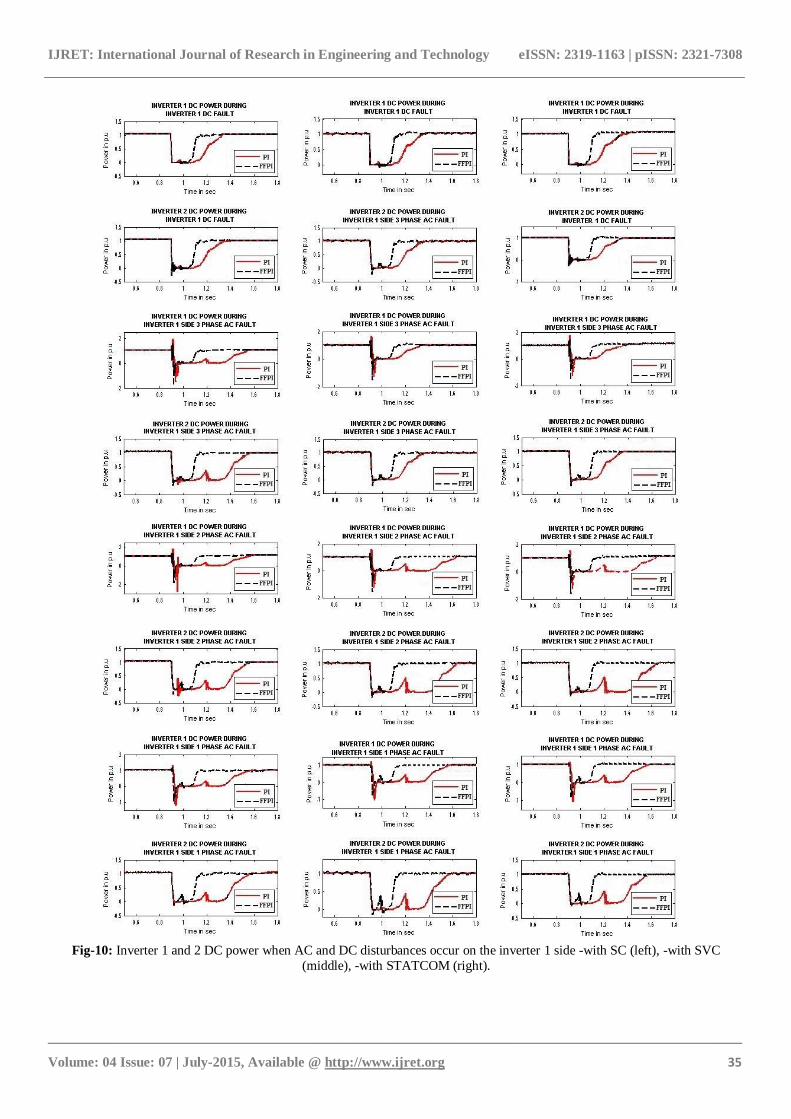
Fig-10: Inverter 1 and 2 DC power when AC and DC disturbances occur on the inverter 1 side -with SC (left), -with SVC
(middle), -with STATCOM (right).
IJRET: International Journal of Research in Engineering and Technology eISSN: 2319-1163 | pISSN: 2321-7308
_______________________________________________________________________________________
Volume: 04 Issue: 07 | July-2015, Available @ http://www.ijret.org 36
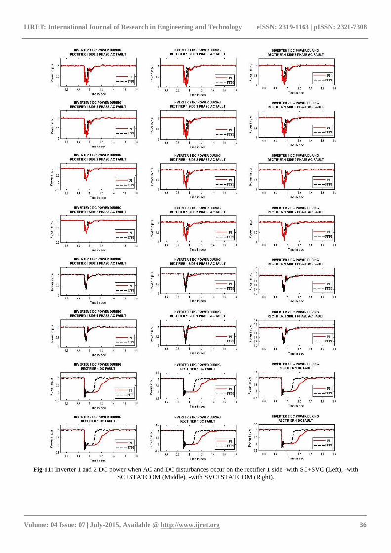
Fig-11: Inverter 1 and 2 DC power when AC and DC disturbances occur on the rectifier 1 side -with SC+SVC (Left), -with
SC+STATCOM (Middle), -with SVC+STATCOM (Right).
IJRET: International Journal of Research in Engineering and Technology eISSN: 2319-1163 | pISSN: 2321-7308
_______________________________________________________________________________________
Volume: 04 Issue: 07 | July-2015, Available @ http://www.ijret.org 37
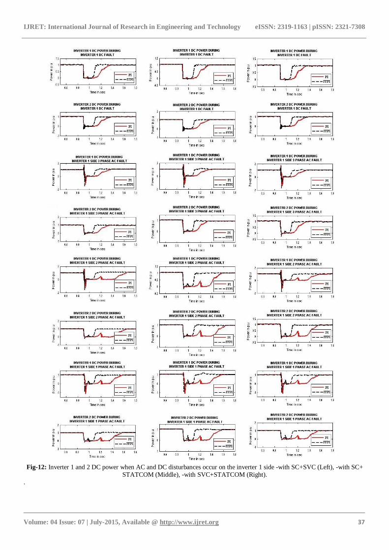
Fig-12: Inverter 1 and 2 DC power when AC and DC disturbances occur on the inverter 1 side -with SC+SVC (Left), -with SC+
STATCOM (Middle), -with SVC+STATCOM (Right).
.
IJRET: International Journal of Research in Engineering and Technology eISSN: 2319-1163 | pISSN: 2321-7308
_______________________________________________________________________________________
Volume: 04 Issue: 07 | July-2015, Available @ http://www.ijret.org 38
Table-1: Harmonics present in the inverter side AC quantities.
% AC Harmonics
for various RPC’s SC SVC STATCOM SC+SVC
SC+
STATCOM
SVC+
STATCOM
Voltage Inverter 1 0.59 1.49 1.32 0.59 1.32 1.43
Inverter 2 0.59 1.49 1.32 0.59 1.32 1.43
Current Inverter 1 8.24 8.54 839 8.54 8.76 8.49
Inverter 2 8.24 8.54 839 8.54 8.76 8.49
Table-2: Level of Over voltage when disturbances occur on the DC line or at the rectifier 1 side during DC block.
TOV for Various
RPC’s in p.u
Rectifier 1 side 3Φ
AC fault
Rectifier 1 side 2Φ
AC fault
Rectifier 1 side 1Φ
AC fault
Rectifier 1 DC
fault
Inverter
1
Inverter
2
Inverter
1
Inverter
2
Inverter
1
Inverter
2
Inverter
1
Inverter
2
SC PI 1.1844 1.1844 1.1675 1.1675 1.1462 1.1462 1.1421 1.1421
FFPI 1.1565 1.1565 1.1382 1.1382 1.1164 1.1164 1.1208 1.1208
SVC PI 1.1956 1.1956 1.1795 1.1795 1.1501 1.1501 1.1558 1.1558
FFPI 1.1724 1.1724 1.1511 1.1511 1.1225 1.1225 1.1311 1.1311
STATCOM PI 1.0932 1.0932 1.0885 1.0885 1.0665 1.0665 1.0937 1.0937
FFPI 1.0624 1.0624 1.0634 1.0634 1.0398 1.0398 1.0683 1.0683
SC+
SVC
PI 1.1457 1.1457 1.1298 1.1298 1.1037 1.1037 1.1064 1.1064
FFPI 1.1168 1.1168 1.1037 1.1037 1.0724 1.0724 1.0885 1.0885
SC+
STATCOM
PI 1.0475 1.0475 1.0337 1.0337 1.0268 1.0268 1.0465 1.0465
FFPI 1.0295 1.0295 1.0256 1.0256 1.0175 1.0175 1.0256 1.0256
SVC+
STATCOM
PI 1.1372 1.1372 1.1141 1.1141 1.0833 1.0833 1.0956 1.0956
FFPI 1.1121 1.1121 1.0962 1.0962 1.0646 1.0646 1.0788 1.0788
Table-3: Inverter 1 and 2 DC power recovery time when AC and DC disturbances occur on the rectifier 1 side.
DC power
recovery time for
Various RPC’s in
seconds
Rectifier 1 Side 3Φ
AC fault
Rectifier 1 side 2Φ
AC fault
Rectifier 1 side 1Φ
AC fault
Rectifier 1
DC fault
Inverter
1
Inverter
2
Inverter
1
Inverter
2
Inverter
1
Inverter
2
Inverter
1
Inverter
2
SC PI 0.090 0.090 0.079 0.079 0.053 0.053 0.399 0.399
FFPI 0.044 0.044 0.037 0.037 0.022 0.022 0.189 0.189
SVC PI 0.099 0.099 0.085 0.085 0.060 0.060 0.412 0.412
FFPI 0.049 0.049 0.042 0.042 0.027 0.027 0.195 0.195
STATCOM PI 0.084 0.084 0.075 0.075 0.048 0.048 0.384 0.384
FFPI 0.039 0.039 0.032 0.032 0.019 0.019 0.178 0.178
SC+
SVC
PI 0.084 0.084 0.073 0.073 0.043 0.043 0.381 0.381
FFPI 0.038 0.038 0.033 0.033 0.015 0.015 0.158 0.158
SC+
STATCOM
PI 0.074 0.074 0.063 0.063 0.034 0.034 0.364 0.364
FFPI 0.025 0.025 0.021 0.021 0.007 0.007 0.148 0.148
SVC+
STATCOM
PI 0.083 0.083 0.072 0.072 0.041 0.041 0.374 0.374
FFPI 0.037 0.037 0.032 0.032 0.014 0.014 0.154 0.154
IJRET: International Journal of Research in Engineering and Technology eISSN: 2319-1163 | pISSN: 2321-7308
_______________________________________________________________________________________
Volume: 04 Issue: 07 | July-2015, Available @ http://www.ijret.org 39
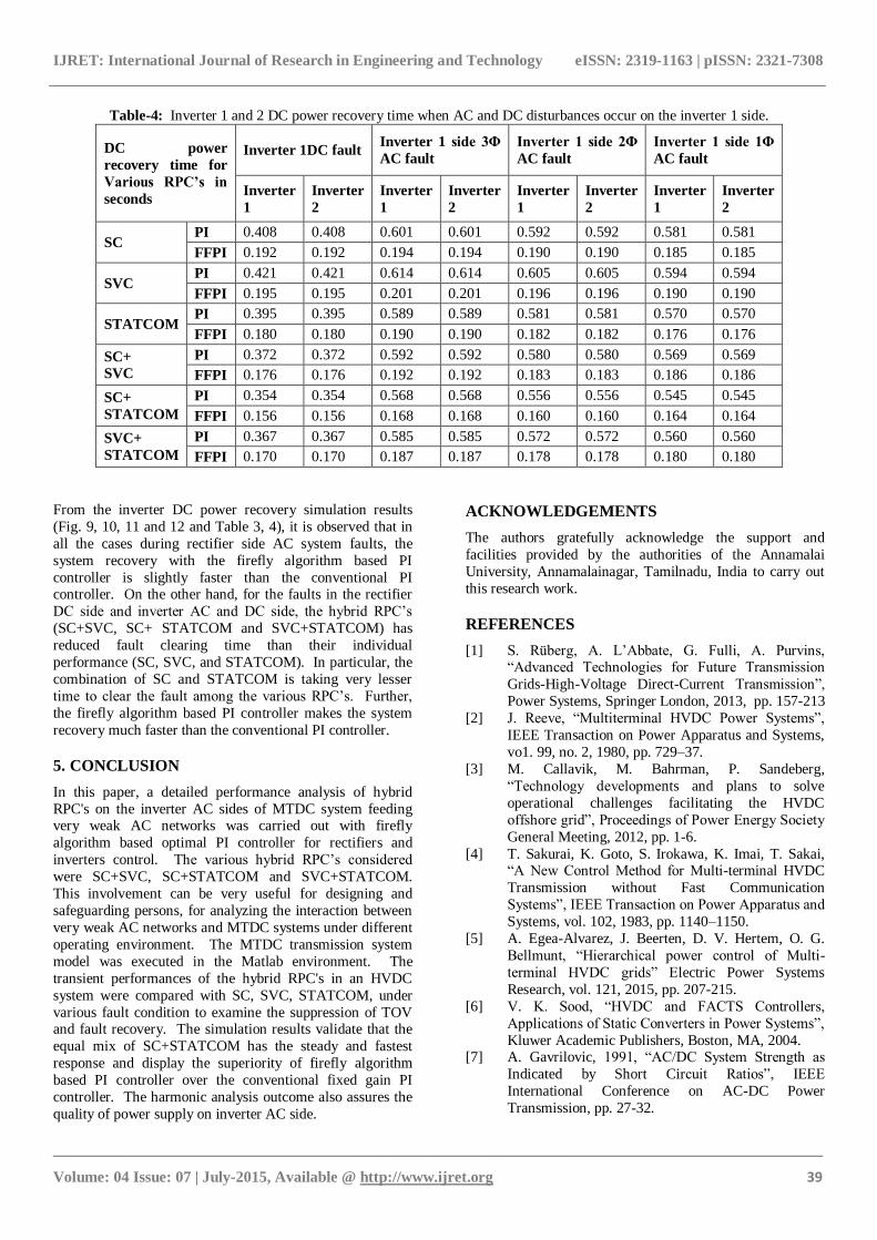
Table-4: Inverter 1 and 2 DC power recovery time when AC and DC disturbances occur on the inverter 1 side.
DC power
recovery time for
Various RPC’s in
seconds
Inverter 1DC fault Inverter 1 side 3Φ
AC fault
Inverter 1 side 2Φ
AC fault
Inverter 1 side 1Φ
AC fault
Inverter
1
Inverter
2
Inverter
1
Inverter
2
Inverter
1
Inverter
2
Inverter
1
Inverter
2
SC PI 0.408 0.408 0.601 0.601 0.592 0.592 0.581 0.581
FFPI 0.192 0.192 0.194 0.194 0.190 0.190 0.185 0.185
SVC PI 0.421 0.421 0.614 0.614 0.605 0.605 0.594 0.594
FFPI 0.195 0.195 0.201 0.201 0.196 0.196 0.190 0.190
STATCOM PI 0.395 0.395 0.589 0.589 0.581 0.581 0.570 0.570
FFPI 0.180 0.180 0.190 0.190 0.182 0.182 0.176 0.176
SC+
SVC
PI 0.372 0.372 0.592 0.592 0.580 0.580 0.569 0.569
FFPI 0.176 0.176 0.192 0.192 0.183 0.183 0.186 0.186
SC+
STATCOM
PI 0.354 0.354 0.568 0.568 0.556 0.556 0.545 0.545
FFPI 0.156 0.156 0.168 0.168 0.160 0.160 0.164 0.164
SVC+
STATCOM
PI 0.367 0.367 0.585 0.585 0.572 0.572 0.560 0.560
FFPI 0.170 0.170 0.187 0.187 0.178 0.178 0.180 0.180
From the inverter DC power recovery simulation results
(Fig. 9, 10, 11 and 12 and Table 3, 4), it is observed that in
all the cases during rectifier side AC system faults, the
system recovery with the firefly algorithm based PI
controller is slightly faster than the conventional PI controller. On the other hand, for the faults in the rectifier
DC side and inverter AC and DC side, the hybrid RPC‟s
(SC+SVC, SC+ STATCOM and SVC+STATCOM) has
reduced fault clearing time than their individual
performance (SC, SVC, and STATCOM). In particular, the
combination of SC and STATCOM is taking very lesser
time to clear the fault among the various RPC‟s. Further,
the firefly algorithm based PI controller makes the system
recovery much faster than the conventional PI controller.
5. CONCLUSION
In this paper, a detailed performance analysis of hybrid
RPC's on the inverter AC sides of MTDC system feeding very weak AC networks was carried out with firefly
algorithm based optimal PI controller for rectifiers and
inverters control. The various hybrid RPC‟s considered
were SC+SVC, SC+STATCOM and SVC+STATCOM.
This involvement can be very useful for designing and
safeguarding persons, for analyzing the interaction between
very weak AC networks and MTDC systems under different
operating environment. The MTDC transmission system
model was executed in the Matlab environment. The
transient performances of the hybrid RPC's in an HVDC
system were compared with SC, SVC, STATCOM, under
various fault condition to examine the suppression of TOV and fault recovery. The simulation results validate that the
equal mix of SC+STATCOM has the steady and fastest
response and display the superiority of firefly algorithm
based PI controller over the conventional fixed gain PI
controller. The harmonic analysis outcome also assures the
quality of power supply on inverter AC side.
ACKNOWLEDGEMENTS
The authors gratefully acknowledge the support and
facilities provided by the authorities of the Annamalai
University, Annamalainagar, Tamilnadu, India to carry out
this research work.
REFERENCES
[1] S. Rüberg, A. L‟Abbate, G. Fulli, A. Purvins, “Advanced Technologies for Future Transmission
Grids-High-Voltage Direct-Current Transmission”,
Power Systems, Springer London, 2013, pp. 157-213
[2] J. Reeve, “Multiterminal HVDC Power Systems”,
IEEE Transaction on Power Apparatus and Systems,
vo1. 99, no. 2, 1980, pp. 729–37.
[3] M. Callavik, M. Bahrman, P. Sandeberg,
“Technology developments and plans to solve
operational challenges facilitating the HVDC
offshore grid”, Proceedings of Power Energy Society
General Meeting, 2012, pp. 1-6.
[4] T. Sakurai, K. Goto, S. Irokawa, K. Imai, T. Sakai, “A New Control Method for Multi-terminal HVDC
Transmission without Fast Communication
Systems”, IEEE Transaction on Power Apparatus and
Systems, vol. 102, 1983, pp. 1140–1150.
[5] A. Egea-Alvarez, J. Beerten, D. V. Hertem, O. G.
Bellmunt, “Hierarchical power control of Multi-
terminal HVDC grids” Electric Power Systems
Research, vol. 121, 2015, pp. 207-215.
[6] V. K. Sood, “HVDC and FACTS Controllers,
Applications of Static Converters in Power Systems”,
Kluwer Academic Publishers, Boston, MA, 2004. [7] A. Gavrilovic, 1991, “AC/DC System Strength as
Indicated by Short Circuit Ratios”, IEEE
International Conference on AC-DC Power
Transmission, pp. 27-32.
IJRET: International Journal of Research in Engineering and Technology eISSN: 2319-1163 | pISSN: 2321-7308
_______________________________________________________________________________________
Volume: 04 Issue: 07 | July-2015, Available @ http://www.ijret.org 40
[8] S. Rao, 2003, EHV-AC HVDC Transmission and
Distribution Engineering, Khanna publishers, New
Delhi, India.
[9] O. B. Nayak, A. N. Gole, “Dynamic Performance of
Static and Synchronous Compensators at an HVDC
Inverter Bus in a Very Weak AC System”, IEEE Transactions on Power Delivery, vol. 9, no. 3, 1994,
pp. 1350-1358.
[10] C. Weindl, G. Herold, D. Retzmann, H. A. Cardona,
I .A. Isaac, G. J. Lopez, 2006, “Feasibility of HVDC
for Very Weak AC Systems with SCR below 1.5”,
IEEE International Conference on Power Electronics
and Motion Control, pp. 1522-1527.
[11] Y. Zhuang, R. W. Menzies, 1996, “Dynamic
Performance of a STATCON at the HVDC Inverter
Feeding a Very Weak AC System”, IEEE
Transactions on Power Delivery, vol. 11, no. 2, pp. 958-964.
[12] S. Seenivasan, S. Singaravelu, “Analysis of a
Monopolar HVDC Transmission System Feeding a
Very Weak AC Network with Hybrid Reactive
Power Compensators and Firefly Algorithm Based
Optimal PI Controller”, International Journal of
Applied Engineering Research, vol. 9, no. 21, 2014,
pp. 10841-10855.
[13] A. Routray, P. K. Dash, S. K. Panda, “A Fuzzy Self-
Tuning PI Controller for HVDC Links”, IEEE
Transactions on Power Electronics, vol. 11, no. 5,
1996, pp. 699-679. [14] P. K. Dash, A. Routary, S. Mishra, “A Neural
Network based Feedback Linearising Controller for
HVDC Links”, Electrical Power Systems Research,
vol. 50, no. 2, 1999, pp. 125-132.
[15] N. Bawane, A. G. Kothari, D. P. Kothari, “ANFIS
Based HVDC Control and Fault Identification of
HVDC converter”, HAIT Journal of Science and
Engineering, vol. 2, no. 5-6, 2005, pp. 673-689.
[16] X. Zhou, C. Chen, Fan Yang, M. Chen,
“Optimization Design of Proportional-Integral
Controllers in High-voltage DC System Based on an Improved Particle Swarm Optimization Algorithm”,
Electric Power Components and Systems, vol. 37, no.
1, 2009, pp. 78-90.
[17] S. Seenivasan, S. Singaravelu, “Modelling and
Simulation of Multi-terminal HVDC Transmission
System Feeding Strong AC Networks with Firefly
Algorithm based Optimal PI Controller”, Global
Journal of Pure and Applied Mathematics, vol. 11,
no. 2, 2015, pp. 579-590.
[18] X. S. Yang, Engineering Optimization: An
Introduction to Metaheuristic Applications, Wiley,
2010. [19] X. S. Yang, “Firefly Algorithms for Multimodal
Optimization”, Stochastic Algorithms: Foundations
and Applications-Springer Berlin Heidelberg, vol.
5792, 2009, pp. 169-178.
[20] X. S. Yang, X. He, “Firefly Algorithm: Recent
Advances and Applications”, International Journal of
Swarm Intelligence, vol. 1, 2013, pp. 36-50.
[21] C. Dufour, J. Mahseredjian, J. Belanger, “A
Combined State-Space Nodal Method for the
Simulation of Power System Transients”, IEEE
Transactions on Power Delivery, vol. 26, no. 2,
2011, pp. 928-935.
BIOGRAPHIES
S. Singaravelu received Bachelor of
Engineering in Electrical and Electronics
in 1990, Master of Engineering in Power
System in 1992 and Ph.D. in 2007 from
Annamalai University, Annamalai nagar,
Tamilnadu, India. At Present, he is a
Professor in the Department of Electrical Engineering at
Annamalai University. His research interests are in power
electronics, power systems, electrical machines, wind/solar
energy applications, high voltage DC transmission and
smart grids.
S. Seenivasan received Bachelor of
Engineering in Electrical and Electronics
in 2005 and Master of Engineering in
Power System in 2011 from Annamalai
University, Annamalai nagar, Tamilnadu,
India. He is currently pursuing Ph.D.
degree in the Department of Electrical
Engineering, Annamalai University. At present, he is an
Assistant Professor in the Department of Electrical
Engineering at Annamalai University. His research interests
are in high voltage DC transmission systems and soft computing techniques.


![A bi-pole ± 285 kV HVDC line HVDC-VSC: transmission ...TG#08].pdf · for building multi-terminal HVDC schemes, as reversing power fl ow does not involve a change of DC polarity,](https://img.pdfslide.net/doc/110x75/5e64eaca2594e126f07d0fa9/a-bi-pole-285-kv-hvdc-line-hvdc-vsc-transmission-tg08pdf-for-building.jpg)