Embed Size (px)
Citation preview

99
ISSN 1999-8716
Printed in Iraq
Vol. 08, No. 02, pp. 99-115, June 2015
ANALYSIS OF PLANE STRAIN ROLLING RIGID
PLASTTIC MATERIALS USING FINITE ELEMENT
METHOD
sTheeyab Fari Saad Assistant Professor, College of Engineering, University of Diyala
(Received: 23/3/2014; Accepted: 18/8/2014)
ABSTRACT: - In this research the rigid plastic material is applied to steady and non-
steady state strip rolling .Stresses and strains distribution in steady state plane strip rolling
under the condition of constant of friction are calculated for work hardening and non-
hardening materials .In order to attain a comprehensive understanding of the underlying
process details, to check and select semi analytical models, highly sophisticated numerical
approaches, based on the method of finite elements (F.E.M), have been performed by
utilizing the non-linear capabilities of both ANSYS-11 Standard and Explicit., Analytical
models, (with different reduction of areas) validated against each other and calibrated with
real process data, are essential to determine proper rolling setups of aluminum (according to
roller diameter, distance between rollers and rolling pressure). The calculated distribution of
roll pressure exhibits, a peak at the entry which does not appear in the analysis by the slab
method. The transverse direction (TD) rotation angle which increases an accurate elongation
control system was built, which is based on precise mathematical process models for the
prediction of rolling pressure, velocity and forward slip. To improve the quality of the rolled
product rolling provides a slight reduction in thickness, thereby eliminating the yield point
elongation focusing on the surface elements which exhibit a compressive stress. The TD
rotation angle in the rolled specimens are very small and permanent deformation due to the
rolling process, these result of completed shapes are in a good agreement with the
experimental ones for aluminum strip .
Keywords: Cold Roll Forming, Rigid Plastic Metal Forming, Finite Element Analysis.
Notation A Area pf roll –strip interface
F External force
g Small positive constant
m Total number of elements
N Total number of nodes
Diyala Journal of Engineering
Sciences
ANALYSIS OF PLANE STRAIN ROLLING RIGID PLASTTIC MATERIALS USING FINITE ELEMENT METHOD
Diyala Journal of Engineering Sciences, Vol. 08, No. 02, June 2015
100
P Roll pressure
Pr normal component of force
R Roll radius
r Reduction in thickness
to Initial thickness
V Volume of element
v Velocity of surface where external force is prescribed
τf Frictional shear stress at roll-strip interface
φ Functional
Angular velocity
RD Rolling direction
ND Normal direction
TD Transverse direction
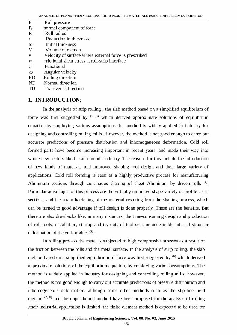
1. INTRODUCTION:
In the analysis of strip rolling , the slab method based on a simplified equilibrium of
force was first suggested by (1,2,3) which derived approximate solutions of equilibrium
equation by employing various assumptions this method is widely applied in industry for
designing and controlling rolling mills . However, the method is not good enough to carry out
accurate predictions of pressure distribution and inhomogeneous deformation. Cold roll
formed parts have become increasing important in recent years, and made their way into
whole new sectors like the automobile industry. The reasons for this include the introduction
of new kinds of materials and improved shaping tool design and their large variety of
applications. Cold roll forming is seen as a highly productive process for manufacturing
Aluminum sections through continuous shaping of sheet Aluminum by driven rolls (4).
Particular advantages of this process are the virtually unlimited shape variety of profile cross
sections, and the strain hardening of the material resulting from the shaping process, which
can be turned to good advantage if toll design is done properly .These are the benefits. But
there are also drawbacks like, in many instances, the time-consuming design and production
of roll tools, installation, startup and try-outs of tool sets, or undesirable internal strain or
deformation of the end-product (5).
In rolling process the metal is subjected to high compressive stresses as a result of
the friction between the rolls and the metal surface. In the analysis of strip rolling, the slab
method based on a simplified equilibrium of force was first suggested by (6) which derived
approximate solutions of the equilibrium equation, by employing various assumptions. The
method is widely applied in industry for designing and controlling rolling mills, however,
the method is not good enough to carry out accurate predictions of pressure distribution and
inhomogeneous deformation. although some other methods such as the slip-line field
method (7, 8) and the upper bound method have been proposed for the analysis of rolling
,their industrial application is limited .the finite element method is expected to be used for

ANALYSIS OF PLANE STRAIN ROLLING RIGID PLASTTIC MATERIALS USING FINITE ELEMENT METHOD
Diyala Journal of Engineering Sciences, Vol. 08, No. 02, June 2015
101
simulating metal forming process because realistic boundary conditions and materials
properties can be taken into account .however ,the rolling process is not easily treated even
by the finite element method because of the difficulties associated with the boundary
condition in that the strip is driven by the frictional force over the roll surface and no
velocity is given by any plane. Most past studies in relation to the finite element method
have assumed no slipping between the strip and the roll surfaces to provide a simple
velocity boundary condition in plane –strain rolling .Employing this assumption (9,10) .The
elastic –plastic F.E analysis of the rolling process is also carried out from an initial non-
steady state to a steady by using the infinitesimal deformation theory to include more
realistic frictional conditions assumed a constant coefficient of friction and analyzed plane-
strain and rigid plastic finite element methods (11). The above reasons lead to the subject of
analysis and optimization software (ANSYS-11), presenting a whole lot of potential to
remedy the situation. To get cold roll forming up and going with all its efficiency, there is a
need to apply methods as early as the profile and tool design phase that can play a major
role in improving the quality of the rolled section.
1.1- The goal
The goal of this research is analyze the cold roll forming process of rigid plastic
material using (ANSYS-11) software program computes the theoretical (elastic and plastic)
strain values on the material during forming as a function of influencing variable like
profile cross section geometry , material gauge , roll configuration or diameter . In this way
it is able to indicate where the material might be overstressed , This fast simulation program
enables to run through a whole series of different shaping variants and to correct the draft
flower or number of shaping stations and toll dimensions as necessary before starting the
actual detailing work or even production of the roll tools, This is time saving and it reduces
the risk of having to rework the roll tool later at start up or even having to make them a
fresh in many cases, the major of poor profile quality is residual local deformation of the
sheet metal (internal strain) produced by elongation during roll forming in addition to the
theoretical figures for such elongation on the top and under side of the metal. Predicts how
the figures are distributed over the cross section. Strain even though the majority of profile
cross sections that are produced are in fact stressed over their entire cross section during roll
forming.
2- TEORY 2.1- Basic equations
. (9) total deformation gradient (F) can be decomposed into two components The

ANALYSIS OF PLANE STRAIN ROLLING RIGID PLASTTIC MATERIALS USING FINITE ELEMENT METHOD
Diyala Journal of Engineering Sciences, Vol. 08, No. 02, June 2015
102
)1(
pFF
X
xF
The velocity gradient (L) is evaluated from the deformation gradient by
)2(1 aLLFFx
vL p
)2(1*** bFFL
Where is the velocity in the deformed configuration, F expresses a time derivative of F, L*
is the contribution of the elastic and lattice rotation to L and L* the plastic contribution.
Considering referencing [13] it is assumed that the strip is slightly compressible in plastic
deformation so the yield criterion for plane –strain deformation is given by
)3(}6)()(){(2
1 22222 mgxyxzzyyx
Where g is a small positive constant, the stress is calculated from the strain rate as follows:-
)4(})9
21(
3
2{
,,
,,,
vxxg
)5(})9
21(
3
2{
,,
,,,
vyyg
)6()9
21( ,
,, y
vzg
)7(3
xy
xy
)8()1
)4
3(
9
4( 2,,2,,,2,, vxyyyxx
g
Consider that a rigid –plastic strip is deformed between rigid rolls under plane –strain
condition with tensile stress applied at the front and tail ends, as shown in fig (1).the strip is
driven by frictional shear stress distributing over the roll surface. The functional defined in
the reference [9] is given as follows for the plastically deforming strip divided into elements.
zRuRuRuRu hhhhhhhh 10)cossincossin2
1 2
11
2
11
22
Where V is the volume of element A the area of roll –strip interface, ∆v the relative
velocity at the interface, F the external force and ν the velocity of the surface where the
external force is prescribed .the correct solution renders the functional a minimum, and when
the value g is as small as 0.01-0.0001; the velocity field which minimizes Ф gives only slight
volumetric strain rate έv and the volume is kept almost constant.
At only one point along the surface of contact between the roll and the sheet, two
forces act on the metal. a radial force Pr and a tangential frictional force F, If the surface
)9()()()(3
1
,2
1
1
1
,,
m
i
ii
m
i
fi
m
i
FvvAV

ANALYSIS OF PLANE STRAIN ROLLING RIGID PLASTTIC MATERIALS USING FINITE ELEMENT METHOD
Diyala Journal of Engineering Sciences, Vol. 08, No. 02, June 2015
103
velocity of the roll Vr equal to the velocity of the sheet, this point is called neutral point or no
slip point (point N in figure (2). Between the entrance plane (xx) and the neutral point the
sheet is moving slower than the roll surface and the tangential friction force F act in the
direction to draw the metal in to the roll. On the exit side (y) of the neutral point, the sheet
moves faster than the roll surface, the direction of the frictional force is then reversed and
opposes the delivery of the sheet from the rolls. Pr is the radial force with a vertical
component Pr (rolling load – the load with which the rolls press against the metal. The
specific roll pressure P is the rolling load divided by the contact area. The distribution of roll
pressure along the arc of contact shows that the pressure rises to maximum at the neutral
point and then falls off. The pressure distribution does not come to a sharp peak at the neutral
which indicates that the neutral point is not really a line on the roll surface but an area. Figure
(3).
2.2- Geometry
The geometry of the initial mesh (Figure 4) is an estimation of the expected steady
state geometry. The mesh movement is kept fixed in rolling direction. The material flows
through the mesh in rolling direction which results in an inflow and an outflow boundary.
The mesh follows the free surface perpendicular to the rolling direction. Internal nodes are
repositioned in order to preserve a sufficient element quality. Due to symmetry only half
specimen was modeled. The steady state rolling continuous rolling of strip without front and
back tension is analyzed. The process geometries and working condition are in as follows in
table (1) and the symmetric boundary conditions were applied to the mid-plane of the
specimen. The reductions in thickness vary from 10% to 60%. The effects of two types of
initial evolution have been investigated. Contact elements are used to describe the contact
between the strip and the tools. These elements are based on a penalty formulation, the tools
are modeled rigid and instead of a force, the motion of the tools is prescribed. This means
that the deformation and the mutual displacement of the tools is not taken into account. In
practice this is an important issue as it affect the final dimensions of the sheet .The material
which has been used for the experiments is Aluminum 6061. This material is modeled with
an elastic – plastic material model with a Von-Misses flow rule. The hardening is described
by the stress – strain curve defined in following equation (14).
][)0261.0(1701)( 2.0 MPay pp ------------------- (11)
The stress of work- hardening material (copper Mpa35.0430 ). The stress-strain
curve for the work-hardening material was obtained from the simple upsetting of a cylinder
made piled-up disks of annealed copper.

ANALYSIS OF PLANE STRAIN ROLLING RIGID PLASTTIC MATERIALS USING FINITE ELEMENT METHOD
Diyala Journal of Engineering Sciences, Vol. 08, No. 02, June 2015
104
2.3 Friction Boundary Condition
If the amount and direction of the frictional shear stress are explicitly given ,the
solution can be obtained simply by minimizing the functional ,equation (4).The frictional
shear stress is a function of the contact pressure, location ,slipping velocity and further ,the
location of the neutral point(or neutral region ).where the direction of frictional shear stress is
reversed, is not known .since coulomb friction has mainly been assumed to be the frictional
law of strip rolling in the aluminum industry ,it will be convenient to employ the law for
practical purposes. In this case, the frictional shear stress is expressed by using a coefficient
of friction .the frictional shear stress is approximated by adopting the roll pressure p in the
previous stage of iteration in the minimizing procedure of Ф. In the analysis of non-steady
state rolling the nodal points are located as a new coordinates after each incremental
deformation since the treatment of boundary condition is complicated if there is not anode at
the corner of the roll corner of the roll entry .The element which has newly come to the entry
corner is exchanged by the element with a singular point and the element which has passed
through the corner is returned to the isoperimetric quadrilateral element.
3- FINITE ELEMENT ANALYSIS
Using ANSYS-11 the finite –element analysis was simulated by building a model
same as the assumed model in theoretical analysis fig. (1). having environmental effect
similar to that of reality and theoretical assumption .The model has to be meshed to a specific
shape of element according to the chosen element which is solid (plane-82) with 8-node
element defined by eight nodes having two degrees of freedom at each node: translations in
the nodal x and y directions. The element may be used as a plane element (preferred) or as an
ax symmetric element. The element has plasticity, creep, swelling, stress stiffening, large
deflection, and large strain capabilities. The sharp directional change of metal flow at the
corner of the roll entry is not easily represented by means of small number elements. To deal
with this problem an element with a singular point which has two velocities at the corner fig.
(3) is employed . Because of symmetry (about x-axis) one half of the model was first solved
later the results showed by symmetry expansion of results. The loading process in ANSYS-11
is employed by applying a horizontal displacement to a work piece at time step according to
the flow velocity at different load step option. The local coordinate technique was used to
locally orient the axis of movement of the work piece (Aluminum) to change with the curved
pass of roller. The rollers according to this technique were assumed to be fixed and squeeze
the work piece into the desired thickness. The roll pressure changed from 100 to 500 Mpa
with different coefficient of friction. Three models were built according to reduction of area
(10, 20, and 60 percent) of the experimental work. The obtained results after applying solves
ANALYSIS OF PLANE STRAIN ROLLING RIGID PLASTTIC MATERIALS USING FINITE ELEMENT METHOD
Diyala Journal of Engineering Sciences, Vol. 08, No. 02, June 2015
105
command were stress, strain shear force, shear stress and energy in both x and y coordinates.
The shape of exit end of the strip was also obtained with the amount of change in element
length before and after rolling process .the roller passed over the strip twice to have the
elongation desired and agree with experimental work obtained from reference [4]
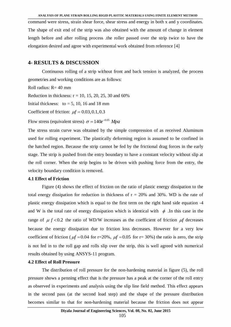
4- RESULTS & DISCUSSION
Continuous rolling of a strip without front and back tension is analyzed, the process
geometries and working conditions are as follows:
Roll radius: R= 40 mm
Reduction in thickness: r = 10, 15, 20, 25, 30 and 60%
Initial thickness: to = 5, 10, 16 and 18 mm
Coefficient of friction: 3.0,1.0,03.0f
Flow stress (equivalent stress) Mpae 05.0140
The stress strain curve was obtained by the simple compression of as received Aluminum
used for rolling experiment. The plastically deforming region is assumed to be confined in
the hatched region. Because the strip cannot be fed by the frictional drag forces in the early
stage. The strip is pushed from the entry boundary to have a constant velocity without slip at
the roll corner. When the strip begins to be driven with pushing force from the entry, the
velocity boundary condition is removed.
4.1 Effect of Friction
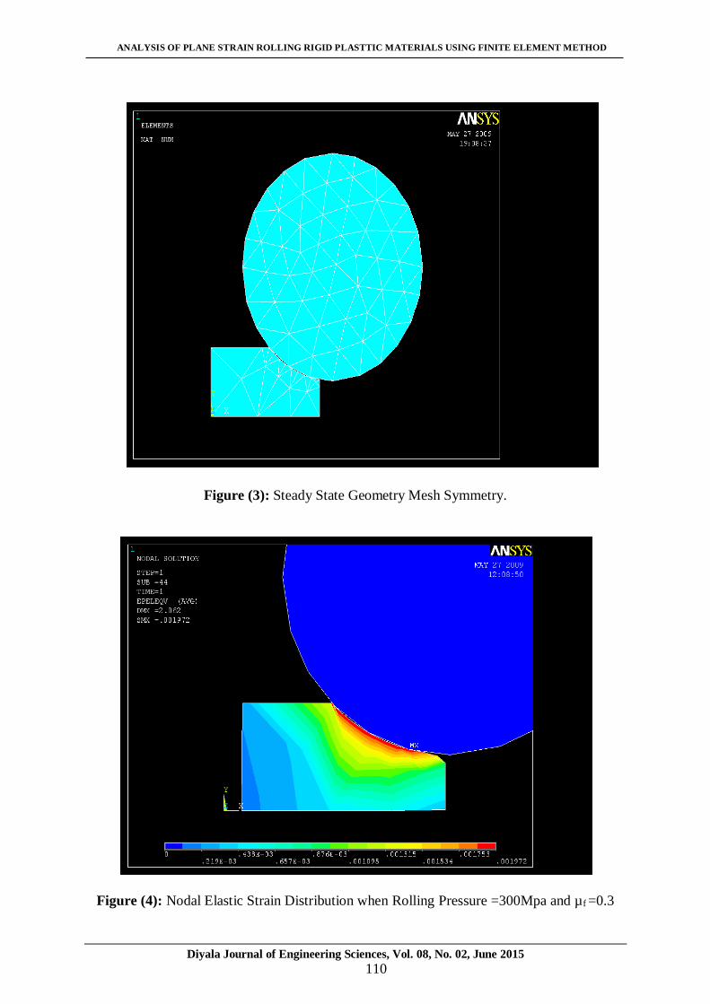
Figure (4) shows the effect of friction on the ratio of plastic energy dissipation to the
total energy dissipation for reduction in thickness of r = 20% and 30%. WD is the rate of
plastic energy dissipation which is equal to the first term on the right hand side equation -4
and W is the total rate of energy dissipation which is identical with .In this case in the
range of 2.0f the ratio of WD/W increases as the coefficient of friction f decreases
because the energy dissipation due to friction loss decreases. However for a very low
coefficient of friction ( 04.0f for r=20%, 05.0f for r= 30%) the ratio is zero, the strip
is not fed in to the roll gap and rolls slip over the strip, this is well agreed with numerical
results obtained by using ANSYS-11 program.
4.2 Effect of Roll Pressure
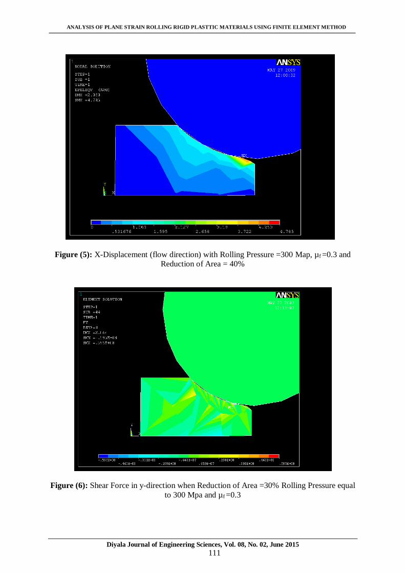
The distribution of roll pressure for the non-hardening material in figure (5), the roll
pressure shows a penning effect that is the pressure has a peak at the corner of the roll entry
as observed in experiments and analysis using the slip line field method. This effect appears
in the second pass (at the second load step) and the shape of the pressure distribution
becomes similar to that for non-hardening material because the friction does not appear

ANALYSIS OF PLANE STRAIN ROLLING RIGID PLASTTIC MATERIALS USING FINITE ELEMENT METHOD
Diyala Journal of Engineering Sciences, Vol. 08, No. 02, June 2015
106
clearly to decrease with the coefficient of friction. In general the position of the peak of the
friction is quite near to that of the natural point or the center of the natural region.
Figure (6) Variation of calculated load with advancement of front end of a Aluminum strip.
The peak of the roll pressure heightened as the strip advance in to the roll gap.
The calculated according to experimental shape of the tail end after rolling are compared for
to=12 mm shows single bulging and in a good agreement with experimental one. Double
bulging was obtained for to = 18 mm. Shear force in y-direction when reduction of area
=30% rolling pressure equal to 300 Mpa mf =0.3. The rotation angles around the TD for
under the reduction of 30% are shown Since both RD rotation angles and ND rotation angles
have near-zero values within the entire region they are not given in the figure .This indicates
that the TD rotation also dominates for Goss initial orientation . It can be seen from that TD
rapidly increases at the entry of the roll bite to the maximum values, and then decreases.
After rolling the rotation angle around TD ( TD) are very small .The cases of 30% reduction
increases the rotation angles around the TD, the rotation angles in the latter are much smaller
than those in the former.
4.3 Effect of Loading
Figures (7, 8, and 9) the calculated load distribution and roll pressure for various stage
of rolling of aluminum at entry and exit are shown of the front end. The velocity boundary
condition that the strip is pushed from the entry boundary is assumed up the point (A) in Fig.
(1) for comparison the experimentally measured load during the steady state is also
illustrated, after the front end emerges from the roll gap. The load kept constant, the
calculated steady state loads agree well with the experimental one and the elongation desired
are agree with experimental work obtained from reference [15,16], the change due to rolling
pressure changing and the velocity that the strip is flow. Figure (10, 11).The effect of friction
coefficient on the ratio of plastic energy dissipation to the total energy.
The strip rolling processes with a constant coefficient of friction under plane – strain
condition were successfully calculated with the present method is effective by obtaining
precise contact pressure distribution and in predicting the non-uniform deformation of the
front end tail ends. The roll pressure during the steady state exhibits two peaks at the neutral
point or region and the roll entry, in the case of non-hardening material and the second pass
of material, whereas the peak at the roll entry is not observed in the first pass of material.
In steady state rolling, the strip is not driven in to the roll gap when the coefficient of
friction is very small when ( 04.0f for r=20%, 05.0f for r= 30%) the front end of the
rolled strip shows a double bulge (when taking full model) and the tail end a single or double
bulge. The calculated Result after rolling agrees well with the experimental as show in

ANALYSIS OF PLANE STRAIN ROLLING RIGID PLASTTIC MATERIALS USING FINITE ELEMENT METHOD
Diyala Journal of Engineering Sciences, Vol. 08, No. 02, June 2015
107
figures (12, 13) and the element consists of triangular sub element igm and quadrilateral
ijkim shown in figure (2) the boundary condition at the corner is well satisfied.
5. CONCLUSIONS
The rigid-plastic finite element method was applied to the analysis of steady and non-steady
state rolling. The steady and non-steady state strip rolling processes with a constant
coefficient of friction under plane-strain condition were successfully simulated .In general the
present method is effective is obtaining precise contact pressure distribution and in predicting
the non-uniform deformation of the front and tail ends .The results of the present analysis are
summarized as follows ;
1) The roll pressure during the steady state exhibits two peaks at the neutral point or region
and the roll entry in the case of non-hardening material and the second pass of work-
hardening material whereas the peak at the roll entry is not observed in the first pass of
work-hardening material.
2) In steady state rolling the strip is not driven into the roll gap when the coefficient of
friction is very small e.g. < 0.04 for r=20٪and < 0.05 for r=30٪.
3) The front end of the rolled strip shows a double bulge and the tail end a single or double
bulge. The calculated end shapes agree well with the experimental ones.
REFERENCES:
1- Tamano .T & Anagimoto. S. Y. “Finite Element Analysis of Steady Metal Flow
Problems” Trans JSME 41, 1130 [1985].
2- Dawson .P.R and Thompson. E. G. “Finite Element Analysis of Steady State Elastio-
Visco Flow by The Initial Stress Rate Method” J .Num .Mech. Eng.12, 47 [1987].
3- Ona. H. & Jimma. T “Prevention of Shape Defects in the Cold – Roll Forming Process of
Wide Profiles” Bulletin of Precision Machinery and Electronics, Tokyo Institute of
Technology No. 53 pp 1-13 [1994].
4- Dobrev A & Halmos G. T. “Roll Design Charlotte .NC. FMAS” Roll Forming Process
Conference [1997].
5- Dong. C. “Deformation Mechanics in Cold – Roll Formed Wide Profiles” M.S. Project.
University of Pittsburgh [1998].
6- Collins. I. F. “Slip Line Field Solution For Compression And Rolling With Slipping
Friction” Int. J. Mech. Sic 11, [1997].
7- Vizur. B “An Upper-Bound Approach to Cold Strip Rolling” J. Eng. Indust. Trans
ASME68-31 [1998].

ANALYSIS OF PLANE STRAIN ROLLING RIGID PLASTTIC MATERIALS USING FINITE ELEMENT METHOD
Diyala Journal of Engineering Sciences, Vol. 08, No. 02, June 2015
108
8- Rao. S and Kumar. K “Finite Element Analysis of Cold Strip Rolling” Int. J Mech Tool
Design. (1998).
9- Mori .K “Simulation of Plane Strain Rolling by the Rigid Plastic finite Element Method”
Int. J. Mech. Sci. Vol. 24, No. 9 pp 519 -527 , 1982
10- Shima S. and Mori K. “Rigid Plastic Finite Element Analysis of Strip Rolling” proc 4th
Int. Conf. Prod. Eng. Tokuo p 80 [1992].
11- Osak. K and Nakano .J “Finite Element Method for Rigid Plastic Analysis of Metal
Forming Formulation” Int. J. Mech. Sci. 24, 459 [1998].
12- Alexander Kainz “Finite Element Modeling of Temper Rolling with Particular Emphasis
on Roughness Transfer” ABAQUS Austria users conference vol. 27/28 pp1-10
September. [2005].
13- Tarnopolskaya Tand. Gates .D. J “Numerical Analysis of Lateral Movement of A metal
Strip during Cold Rolling” ANZIM .J 45 pp 173-186 [2004].
14- Stefqnik A “Slitting Criterion for Various Rolling Speeding in MSR Rolling Process”
AMME Journal of achievements in materials and manufacturing engineering vol. 27 pp.
94-104 [2008].
15- Oladipo. Jr. Onipede “Simulation of Cold Roll Forming of Steel Panels” Mechanical
Engineering Department, University of Pitsburgh. Benedum Engineering Hall 3700 Q.
Hara Street office 648 USA [2008].
16- Klaus Hulka “The Role of Niobium in Low Carbon Bainitic Hsla Steel” Niobium
Products Company Gmbh, Dusseldorf, Germany [2009].
Table (1): Geometric Properties Model for Steady State Rolling used in this research.
Main Roller Diameter 400 mm
Velocity of the Plate 1500 mm / sec
Dimension of the Plate 1500 x 500 x 5 mm
Case 1 Case 2 Case 3
Center to Center Distance 300 mm 300 mm 300 mm
Displacement of Bottom Roller
Applied
90 mm 90 mm 90.01 mm
Static Dynamic Friction 0/0 0/0 0.02 / 0.01
Coefficient of friction µ 0.03 0.1 o.3
Initial thickness to = 5,10,16,18, mm
Reduction in thickness
r = 8,10,20,30,40,50%

ANALYSIS OF PLANE STRAIN ROLLING RIGID PLASTTIC MATERIALS USING FINITE ELEMENT METHOD
Diyala Journal of Engineering Sciences, Vol. 08, No. 02, June 2015
109
Figure (1): General idea of Modeling of Plane –Strain Rolling
Figure (2): Treatment of Velocity Boundary Condition at Corner or Roll Entry
(a) Triangular sub- element ijm and quadrilateral sub – element ijkm
(b) Element with a singular
ANALYSIS OF PLANE STRAIN ROLLING RIGID PLASTTIC MATERIALS USING FINITE ELEMENT METHOD
Diyala Journal of Engineering Sciences, Vol. 08, No. 02, June 2015
110
Figure (3): Steady State Geometry Mesh Symmetry.
Figure (4): Nodal Elastic Strain Distribution when Rolling Pressure =300Mpa and µf =0.3
ANALYSIS OF PLANE STRAIN ROLLING RIGID PLASTTIC MATERIALS USING FINITE ELEMENT METHOD
Diyala Journal of Engineering Sciences, Vol. 08, No. 02, June 2015
111
Figure (5): X-Displacement (flow direction) with Rolling Pressure =300 Map, µf =0.3 and
Reduction of Area = 40%
Figure (6): Shear Force in y-direction when Reduction of Area =30% Rolling Pressure equal
to 300 Mpa and µf =0.3

ANALYSIS OF PLANE STRAIN ROLLING RIGID PLASTTIC MATERIALS USING FINITE ELEMENT METHOD
Diyala Journal of Engineering Sciences, Vol. 08, No. 02, June 2015
112
Figure (7): Shape Change of Front End of an Aluminum Strip according to Loading Step and
Rolling Pressure.
Figure (8): Calculated Distribution of Roll Pressure for Various Stage of Rolling of
Aluminum at Entry and Exit
0
5
10
15
20
25
1 3 5 7 9 11
Ro
ll p
ress
ure
( M
pa*
100)
(Entry) l (mm ) (Exit)
l= 36 mm
l= 20 mm
l = 17 mm
l = 13 mm
l = 9 mm

ANALYSIS OF PLANE STRAIN ROLLING RIGID PLASTTIC MATERIALS USING FINITE ELEMENT METHOD
Diyala Journal of Engineering Sciences, Vol. 08, No. 02, June 2015
113
Figure (9): Variation of Calculated Load with advancement of Aluminum
Strip when µf =0.15, 0.25 at Entry and Exit
Figure (10): The effect of friction coefficient on the ratio of plastic energy
Dissipation to the total energy
Figure (11): The Average Effective Strain with different Contact Surfaces
Between Aluminum and Rollers with Variation Friction Factor
0
0.5
1
1.5
2
2.5
1 3 5 7 9 11 13 15
Friction factor *100
Ave
rag
e E
ffec
tive
Str
ain
re
Ri=5mm
Ri=10mmRi=20mm
-5
0
5
10
15
20
25
30
35
40
1 2 3 4 5 6 7 8
Lo
ad
/Bre
ad
th (
KN
/MM
)
Entry l mm Exit
mf = 0.25
mf = 0.15
0
20
40
60
80
100
120
1 2 3 4 5 6 7
friction coefficient (mf)
WD
/W (
%)
r=20%
r=30%

ANALYSIS OF PLANE STRAIN ROLLING RIGID PLASTTIC MATERIALS USING FINITE ELEMENT METHOD
Diyala Journal of Engineering Sciences, Vol. 08, No. 02, June 2015
114
Figure (12): External Load and Displacement curves Comparison between calculated
and experimental (no lubrication) after rolling for to = 12 mm, 25.0mf ,(9)
.
Figure (13): Distributions of radial strain on initial radius when the external load
equal 800 kg comparison of theory result, F.E.M and Experimental.
-200
0
200
400
600
800
1000
1200
1400
1 2 3 4 5 6 7 8 9 10
Displacement Wp (mm)
Exte
rnal L
oad P
( k
g)
model 1
Expermentalmodel 1
Theorymodel 2
Expermentalmodel 2
Theory
0
0.01
0.02
0.03
0.04
0.05
0.06
1 2 3 4 5 6 7
Ra
dia
l s
tra
in
Initial radius ( r/ b)
External load P=800 kg Numerical
Theoretical
Experimental

ANALYSIS OF PLANE STRAIN ROLLING RIGID PLASTTIC MATERIALS USING FINITE ELEMENT METHOD
Diyala Journal of Engineering Sciences, Vol. 08, No. 02, June 2015
115
تحليل االنفعال المستوي لعملية الدرفلة لمادة صلبة لدنة باستخدام طريقة العناصر المحددة
سعد ذياب فارس
جامعة ديالى ،استاذ مساعد، كلية الهندسة
الخالصة:للدرفلة االنزالقية وبتوزيع فى هذا البحث تم استخدام مادة صلبة لدنة لحالة االستقرارية وعدم االستقرارية
االنفعاالت واالجهادات في حالة االستقرار تحت ظروف االحتكاك الثابت وحسابها بوجود التصليد والالتصليداالنفعالي السرعة واالنزالق لالمام للحصول ،للمادة. وتم بناء نظام دقيق للسيطرة على عملية االستطالة عند الدرفلة للتنبؤ بالضغط
صف لما يحدث فى الطبقات التحتية للصفيحة المدرفلة.استخدم تقريب عددى لمعرفة دقة وتنظيم الموديالت على ادق و ( باالعتماد على طريقة العناصر المحددة. استغل التماثل و Ansys-11) لية باستخدام التحليل الالخطى فى برنامجالتحلي
فى حالة كون معامل االحتكاك ثابت للمعادن للدرفلة ثنائية االبعادالتقدم فى معرفة االجهاد واالنفعال فى الحالة المستقرة المسافة بين ،ي المساحة طبقا الى قطر الدرفيلغير المصلدة. تم بناء موديل تحليلي وامكن تحديده في مقدار التخصر ف
.تصميم لعملية الدرفلة لاللمنيوم الدرفيل وضغط الدرفيل للحصول على انسبفلة الناشئ وكان ذروته في مقدمة الدخول للدرفيل والذي لم يظهر بطريقة التسطيح اما تم حساب ضغط الدر
ه لعب دورمهما في الدوران حول اتجاه الدرفيل واالتجاه الطبيعي اهمل واتجاه انتقال زاوية الدوران يزداد بزيادة التخصروانامكن تحديده مع عدة منحنيات بحيث قورنت . شكل الصفيحة بعد الدرفلة ومقدار استطالة العناصر تقويم الدرفلة
الموديالت التحليلية المختلفة فى مقدار التقليل فى المساحة مع النتائج العملية للحصول على انسب تصميم لعملية الدرفلة ية لاللمنيوم ولتحسين نوعية المنتج والسيطرة على الدرفلة االنتاجية مع اعطاء وصف نهائى لعملية الدرفلة ولكون عمل
الدرفلة تحدث تغيير قليل فى السمك تتحدد نقطة الخضوع لالستطالة مع التركيز على العناصر السطحية التى تتعرض الى اجهاد انضغاطى وتشويه دائم يزداد بزيادة التخصر. زاوية الدوران لنموذج الدرفلة صغيرة جدا وهذه النتائج للشكل
. العملية لاللمنيوميد مع النتائج النهائي كانت متوافقة بشكل ج